

Page 1
Avocent® Local Rack Access 18.5"LEDLCDConsole
With Integrated Keyboard, Touchpad and Dual USB2.0 Ports
Installer/User Guide
Page 2

For important safety information, visit:
www.emersonnetworkpower.com/ComplianceRegulatoryInfo
Emerson, Emerson Network Power and the Emerson Network Power logo are trademarks or service marks of Emerson Electric
Co. Avocent and the Avocent logoare trademarks or service marks of Avocent Corporation. Allother marks are the property of their
respective owners. This document may containconfidential and/or proprietary information of Avocent Corporation,and its receipt or
possessiondoes not convey any right to reproduce, disclose its contents, or to manufacture or sell anything that it may describe.
Reproduction, disclosure, or use without specific authorization from Avocent Corporation is strictly prohibited. ©2014 Avocent
Corporation.Allrights reserved.
Page 3

TABLE OF CONTENTS
iii
Overview
Installation
Avocent® Local Rack Access 18.5"LEDLCDConsolecontents
Installation tools
Installing in a standard EIARack
Installing the LCDtray
Attaching the cable management arm
Connecting the LCD tray
Removing the LCDtray from the rack
Removing the rails
Using the Monitor
Monitor user controls
Appendices
Appendix A:Technical Specifications
Appendix B:USB2.0 Speed Chart
1
3
3
3
4
5
6
6
7
8
9
9
11
11
12
Page 4

Page 5

Overview
The Avocent® Local Rack Access 18.5"LEDLCDConsole functions as an SVGA monitor and
keyboard tray in one unit. It is available with an option of USB or PS/2 for the keyboard. It also has
two USB2.0 compliant pass-through ports, which provide faster data transmission between your
console and connected USB2.0 devices. For more information, see the USB2.0 Speed Chart on
page 12.
The console occupies 1RU (EIA term where 1RU = 1.75" of mounting height) of vertical space in a
rack. This unit is installed with slide rails that will accommodate an Avocent®branded KVM
appliance in the same 1RU.
Page 6

2.....Local Rack Access LEDLCDConsole Installer/User Guide
Page 7

Installation
CAUTION: The AC adaptor that is connected to the LCD monitor is not intended for use with other
products. Do not disassemble the LCD monitor or remove the AC adapter.
NOTE: The cabinet side rails may be boxed separately. If you are installing more than one unit at the same
time, make sure to keep the outer slides with the same inner slides (mounted on the LCD tray) as matched
pairs. Rails and units that shipped together must be paired together. Mismatched pairs may result in a
damaged installation.
Avocent® Local Rack Access
18.5"LEDLCDConsolecontents
All products contain the following items:
• One Avocent® Local Rack Access 18.5"LEDLCDConsole with built-in LCD monitor,
keyboard, dual USB2.0 ports and cable management arm
• Two outer rails
• Miscellaneous hardware kit (user guide, safety sheet, cage nuts, clip nuts, screws and cable
straps)
Installation tools
You will need the following tools (not provided)to install the LCD/keyboard tray:
• One No. 2 Phillips screwdriver
• One cage-nut-insertion tool or flat-blade screwdriver (for installing cage nuts in some racks)
Page 8

4.....Local Rack Access LEDLCDConsole Installer/User Guide
Installing in a standard EIARack
Installing the Rails in a Standard EIARack
To install the rails into a standard EIArack:
1. Install a cage nut into the RU position on the front flange of the rack where you are going to
install the rails.
2. Install the front of the rail so that the pins are in the bottom two positions in the RU space.
3. Insert a supplied screw into the cage nut to secure the front of the rail to the rack.
NOTE: Do not tighten the screw until the unit is installed to allow for adjustment during installation.
4. Insert the rear of the bracket into the rack, making sure it locks into place.
5. Repeat steps 1-4 for the rail on the other side of the rack.
Page 9

Installing the LCDtray
Installing the LCDTray
Installation.....5
To install the LCDtray:
NOTE: The slide rails have front and rear detents for retention. Be careful not to damage them during
installation.
1. Ensure that the ball-bearing race is in the forward most position, touching the lead-in plastic
guide.
WARNING: Failure to engage the ball-bearing assembly with the plastic guide can cause damage to your
rail.
2. Extend the inner part of the outer rails and slide the ball-bearing assemblies forward to the
front of the outer rails.
3. Carefully slide the LCD tray into the ball-bearing assemblies in the rails. If necessary, loosen
the Velcro®straps on the cable retractor to allow free and smooth movement of the cable
retractor arm.
4. Align the unit with the rails, keeping the unit parallel at all times. Push the LCD tray completely
into the rack. Pull the LCD tray out to the extended detent and then push it back into the
docked position to seat the unit properly in the rails. The slide rails should roll smoothly.
NOTE: The set screws can be tightened after the unit is installed and centered.
Page 10
6.....Local Rack Access LEDLCDConsole Installer/User Guide
Attaching the cable management arm
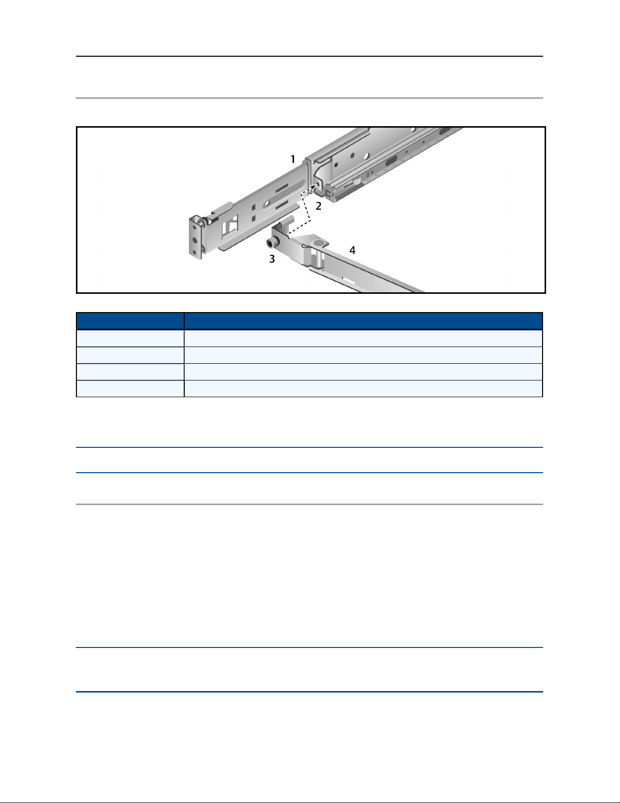
Attaching the Cable Management Arm (CMA)
Attaching the Cable Management Arm Description
Number Description
1 Outer rail
2 CMAAttachment Bracket
3 Thumb screw
4 Cable management arm (CMA)
Attach the CMA to the outer slide-rail bracket by sliding the CMA bracket over the slide-rail mount
and using the thumbscrew to secure the CMA.
NOTE: A Phillips head screw driver may be used to tighten the thumbscrew in tightly-spaced racks.
Connecting the LCD tray
To connect the LCDtray:
1. Connect the video, keyboard and mouse connectors to either a server or a console switch in
the rack cabinet.
2. Connect the power cord to a properly grounded electrical outlet or power distribution unit
(PDU).
3. (Optional) Bundle excess cables into a figure-eight loop and secure with a cables strap.
NOTE: Do not coil the cables. To minimize electrical interference from the video cable, arrange the cable in
figure-eight loops.
Page 11

Removing the LCDtray from the rack
Removing the LCDTray from the Rack
Installation.....7
Removing the LCD Tray Descriptions
Number Description
1 LCDtray
2 Inner rail
3 Outer rail
4 Release locking tab
To remove the LCDtray:
NOTE: The slide rails have front and rear detents for retention. Be careful not to damage them during
removal.
1. Disconnect the LCDtray from all power and signal connections.
2. Unscrew the thumbscrew to disengage the CMAfrom the slide rail and prepare the cables for
removal from the rack.
3. Pull the LCDtray out from the rack until the detent engages.
4. When the detent engages, push the tab in along the inner rail and continue to slide the
LCDtray out of the rack.
NOTE: When removing an LCDtray, make sure you remove and replace all slide rail bracketing in the rack.
The slide rail assemblies should remain with the unit they shipped with.
Page 12

8.....Local Rack Access LEDLCDConsole Installer/User Guide
Removing the rails
Removing the rails
To remove the rails from the rack:
1. Remove the screw holding the front of the rail to the rack.
2. Pull the release tab to release the rail from the rack.
3. Pull the rail away from the rack.
4. Repeat steps 1-3 for the rail on the other side.
5. Remove the rear rack connection in the same manner as you did for the front connection.
Page 13
Using the Monitor
The following section contains basic information about using the monitor.
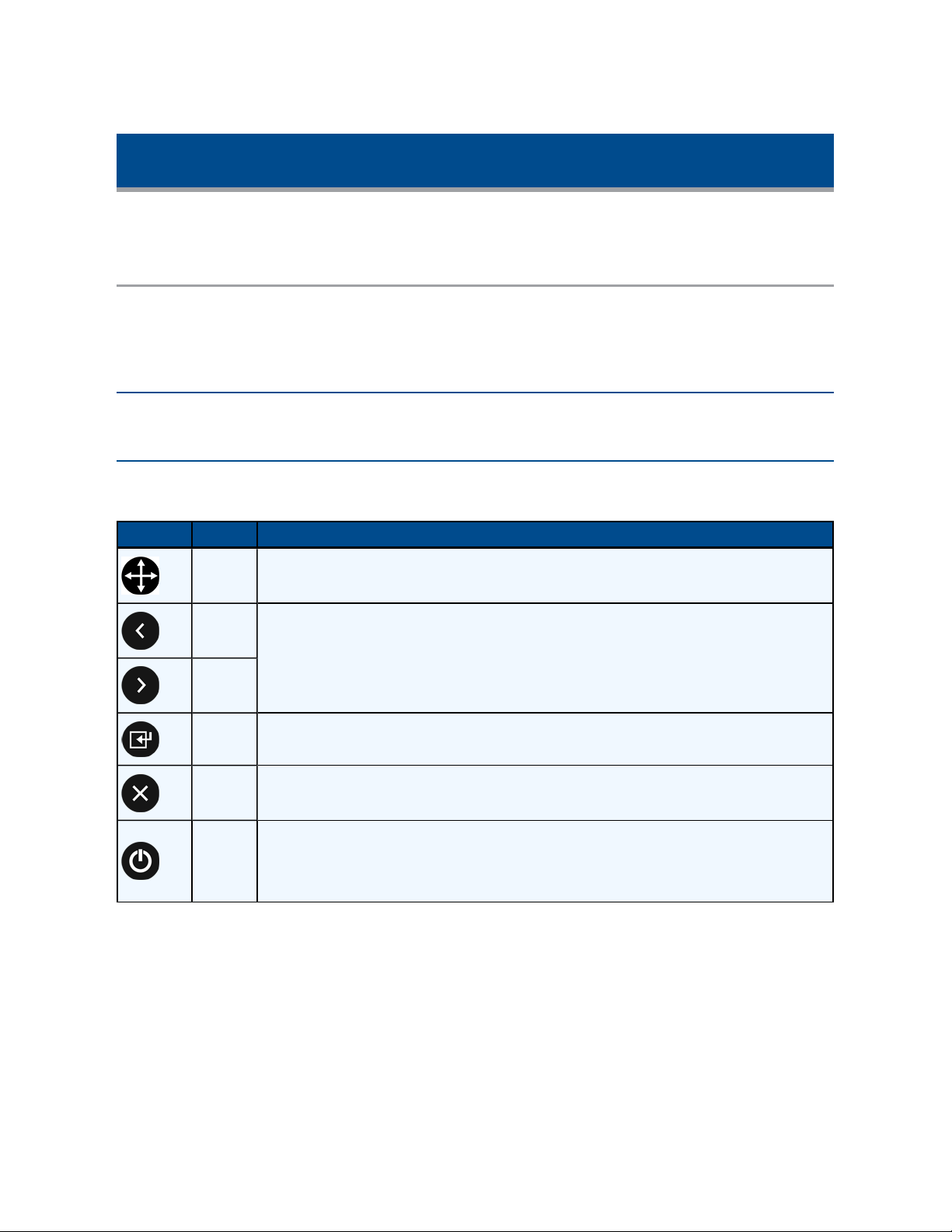
Monitor user controls
Use the control buttons on the front of the monitor to adjust the characteristics of the image that is
displayed. The button images will match the instructions in the on-screen display (OSD)menu. All
of the user control buttons on this unit are capacitive.
NOTE: There may be a slight delay in response time after pressing a button. Repeatedly pressing a button
will result in multiple responses.
The user controls on the front of the LCD monitor function are detailed in the following table:
LCD Monitor User Control Descriptions
Icon Control Description
Auto Press this button to automatically adjust the monitor settings.
Left
arrow
Right
arrow
Menu Press this button to display the OSDmenu and to move the selector on the OSDmenu.
Exit Press this button to exit from the OSDfunction or to go back to the previous menu.
Power
Press one of these buttons to select the function that is to be adjusted. Once you've
selected the adjustment, use the arrow keys to increase or decrease the value of the
selected adjustment.
Press this button to turn the monitor on and off. When it's illuminated blue, the monitor
is in normal operation. When it's illuminated amber, the power is good but there is no
video signal. When it blinks amber, the monitor is in standby. When it is black, the
power is off.
Page 14
10.....Local Rack Access LEDLCDConsole Installer/User Guide
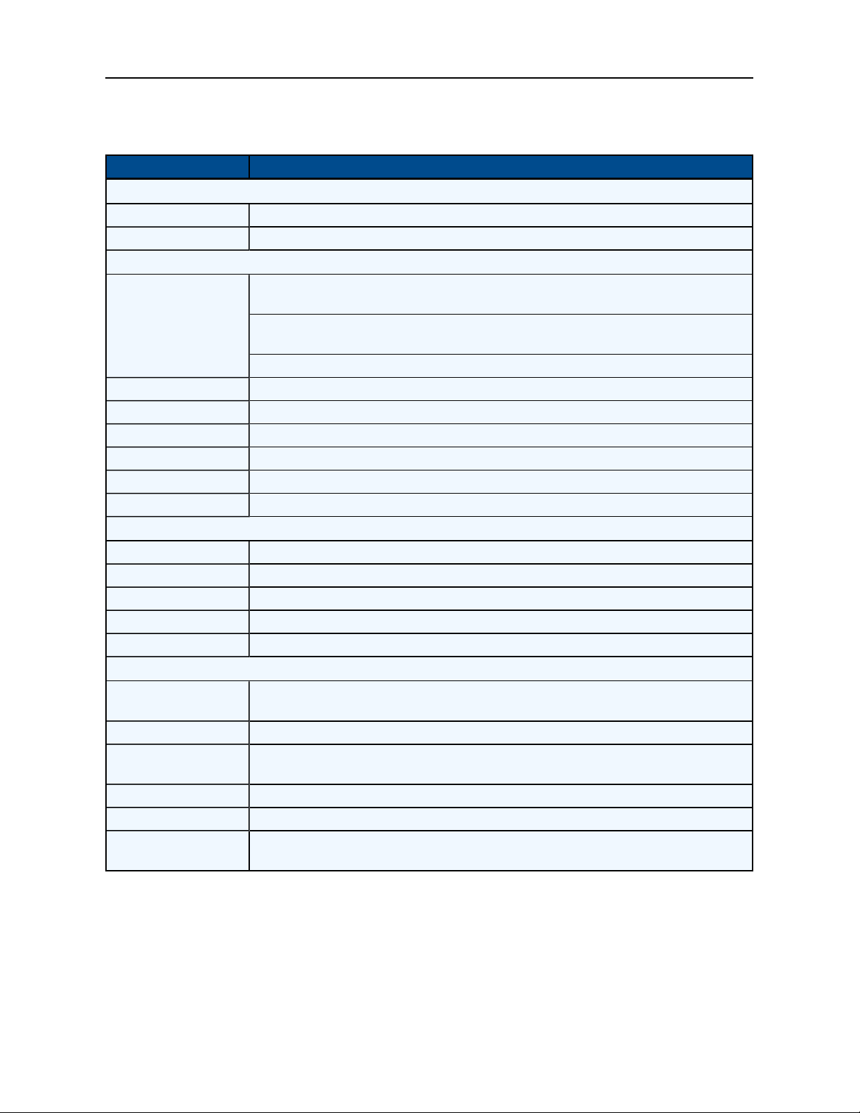
The following table describes the menu control options.
Menu Control Options
Setting Description
Brightness/Contrast
Brightness Adjusts the brightness for the monitor
Contrast Adjust the contrast for the monitor
Display Settings
1:1 gives the actual pixel representation on the screen. Use this only if the resolution
is less than 1366 x 768
Viewing mode
Horizontal Position Click the left and right arrows to adjust the image left and right
Vertical Position Click the left and right arrows to adjust the image up and down
Sharpness Adjust the sharpness of the image
Pixel Clock Adjust how coarse the image is
Phase Adjust how fine the image is
Reset Display Settings Resets the settings to their factory default
Color Settings
Standard The monitor uses the standard color settings
Warm The monitor uses the warm color settings
Cool The monitor uses the cool color settings
Reset Color Settings Resets the color setting to their factory default
Auto Adjust Automatically sets the monitor settings
Other Settings
Language
Menu Timer Sets the menu timer
DDC/CI
LCDConditioning Enables LCDConditioning to help eliminate any image retention
Reset Other Settings Resets to the other settings to the factory default
Factory Reset/Version
Information
Aspect fills the screen to the largest amount of space without altering the aspect
ratio
Fill fills the screen completely
Sets the display for English, German, Spanish, French, Japanese, Simplified
Chinese or Korean
Enables Display Data Channel/Command Interface to permit software on your
computer to adjust the settings for the monitor
Resets the monitor to its factory default
Page 15

Appendices
Appendix A:Technical Specifications
Technical Specifications
Category Value
LCDPanel
Size 18.5-inch diagonal
Display area (horizontal x vertical) 409.8 x 230.4 mm
Type TFTactive matrix
Pixel pitch (horizontal x vertical) 300 x 300 mm
Characteristics
Brightness 250 cd /m2 (Typ.)
Contrast ratio 1000:1 (Typ.)
Display color 16.7 million colors
Viewing angle Horizontal - 170°
Vertical - 160°
Aspect ratio 16:9 (native)
Scaling 1:1, Aspect and Fill
Display Resolution
Optimum Mode 1366 x 768 at 60 Hz
Maximum Mode 1600 x 1200 at 60 Hz
Connector VGA
Power Supply AC 100 - 240 V, 60 Hz - 50 Hz to DC 12 v/3.3 A
Power Consumption
Standard usage 17 watts
Maximum usage 22 watts
Power supply maximum 40 watts
Power saving Less than 1 watt
Environmental Conditions
Operating temperature 0°C to 50°C
Operating humidity 10%to 80%
Operating altitude Maximum 3000 meters
Storage temperature -20°Cto +60°C
Storage humidity 5% to 95%
Keyboard
Type 103 key keyboard with touchpad, USB or PS/2, plug and play
Page 16

12.....Local Rack Access LEDLCDConsole Installer/User Guide
Appendix B:USB2.0 Speed Chart
USB Maximum Speed Chart
Device/Target USB 1.1 Target USB2.0 Target USB3.0 Target
USB 1.1 device 12 megabits per second 12 megabits per second 12 megabits per second
USB2.0 device 12 megabits per second 480 megabits per second 480 megabits per second
USB3.0 device 12 megabits per second 480 megabits per second 480 megabits per second
Page 17

Technical Support Site
If you encounter any installation or operational issues with your product, check the pertinent section
of this manual to see if the issue can be resolved by following outlined procedures. For additional
assistance, visit www.avocent.com/support.
Avocent Community Support Site
To search product knowledge content,
visit community.emerson.com/networkpower/support/avocent.
Page 18

About Emerson Network Power
Emerson Network Power, a business of Emerson (NYSE:EMR), delivers software, hardware and services thatmaximize
availability, capacity andefficiency for data centers, healthcare and industrialfacilities. A trusted industry leader insmart
infrastructure technologies, Emerson Network Power provides innovative data center infrastructure management solutions
that bridgethe gap between IT and facility management and deliver efficiency and uncompromised availability regardless of
capacity demands. Our solutions are supported globally by local Emerson Network Power service technicians. Learn more
about Emerson Network Power products and services at www.EmersonNetworkPower.com.
590-1193-501A
 Loading...