

Page 1

LongView
®
Installer/User Guide
IP
Page 2

USA Notification
Warning: Changes or modifications to this unit not expressly approved by the party
responsible for compliance could void the user’s authority to operate the equipment.
Note: This equipment has been tested and found to comply with the limits for a Class A
digital device, pursuant to Part 15 of the FCC Rules. These limits are designed to provide
reasonable protection against harmful interference when the equipment is operated in a
commercial environment. This equipment generates, uses and can radiate radio frequency
energy and, if not installed and used in accordance with the instruction manual, may cause
harmful interference to radio communications. Operation of this equipment in a residential
area is likely to cause harmful interference in which case the user will be required to
correct the interference at his own expense.
Canadian Notification
This digital apparatus does not exceed the Class A limits for radio noise emissions from
digital apparatus set out in the Radio Interference Regulations of the Canadian Department
of Communications.
Le présent appareil numérique n’émet pas de bruits radioélectriques dépassant les limites
applicables aux appareils numériques de la classe A prescrites dans le Règlement sur le
brouillage radioélectrique édicté par le Ministère des Communications du Canada.
Safety and EMC Approvals and Markings
UL, FCC, cUL, CE
Sound Level Measure
The measured sound level of this appliance is 44.7 dB(A).
Die arbeitsplatzbezogene Geräuschemission des Gerätes beträgt 44,7 dB(A).
Page 3

LongView® IP KVM Extender
Installer/User Guide
Avocent, the Avocent logo, The Power of Being There and LongView are
registered trademarks of Avocent Corporation or its affiliates. All other
marks are the pro p e r ty of their respectiv e ow ners.
© 2007 Avocent Corporation. All rights reserved . 59 0-721-617A
Page 4
Instructions
This symbol is intended to alert the user to the presence of important operating and maintenance
(servicing) instructions in the literature accompanying the appliance.
Dangerous Voltage
This symbol is intended to alert the user to the presence of uninsulated dangerous voltage within the
product’s enclosure that may be of sufficient magnitude to constitute a risk of electric shock to persons.
Power On
This symbol indicates the principal on/off switch is in the on position.
Power Off
This symbol indicates the principal on/off switch is in the off position.
Protective Grounding Terminal
This symbol indicates a terminal which must be connected to earth ground prior to making any other
connections to the equipment.
Page 5

TABLE OF CONTENTS
Table of Contents
List of Figures .................................................................................................................. v
List of Tables..................................................................................................................vii
Chapter 1: Product Overview.................... ....... ...... ....... ...... ...... ....... ...... ....... ...... ....... ..... 1
Features and Benefits ........................................................................................................................1
Safety Precautions .............................................................................................................................3
Chapter 2: Installation ...................................... ...... ....... ...... ...... ....... ............................... 5
Getting Started.......................................... ...... ...... .................................. ..... ......................................5
Items needed to install the LongView IP KVM extender............................................................5
Optional items.............................................................................................................................5
Mounting Option................................................................................................................................5
Installation Options ...........................................................................................................................6
Point-to-point installation ..........................................................................................................6
Connecting power.......................................................................................................................8
Networked installation................................................................................................................8
iii
Chapter 3: Operations ...................................... ...... ....... ...... ...... ....... ............................. 11
Overview..........................................................................................................................................11
LED identification ....................................................................................................................11
Accessing the System .......................................................................................................................12
The Serial Menu...............................................................................................................................12
Accessing the serial menu.........................................................................................................12
Navigating the serial menu.......................................................................................................13
Configuring Network Settings..........................................................................................................13
Configuring Video Input Settings ....................................................................................................18
Detecting a Transmitter IP Address................................................................................................19
Authentication..................................................................................................................................20
Flash Upgrading the LongView IP KVM Extender...................................................... ...... .............23
Restoring Factory Default Settings..................................................................................................24
Resetting the LongView IP KVM Extender......................................................................................24
Viewing System Information............................................................................................................25
Session Retry Settings..................................... .................................. ...... ..... ....................................25
Page 6

iv LongView IP KVM Extender Installer/User Guide
Audio Performance Settings............................................................................................................26
Appendices..................................................................................................................... 29
Appendix A: Technical Specifications.............................................................................................29
Appendix B: Factory Default Settings............................................................................................. 33
Appendix C: Technical Support.......................................................................................................34
Appendix D: Troubleshooting..........................................................................................................35
Page 7

LIST OF FIGURES
List of Figures
Figure 1.1: LongView IP KVM Extender - Basic System..................................................................1
Figure 2.1: Point-to-point Installation..............................................................................................6
Figure 2.2: Receiver and Transmitter Installation............................................................................7
Figure 2.3: Networked Installation ...................................................................................................8
Figure 3.1: Com1 Properties Menu.................................................................................................13
Figure 3.2: Transmitter Main Menu................................................................................................14
Figure 3.3: Transmitter Network Configuration Menu...................................................................14
Figure 3.4: Receiver Main Menu.....................................................................................................15
Figure 3.5: Transmitter Configuration Menu on the Receiver........................................................15
Figure 3.6: Receiver Main Menu.....................................................................................................16
Figure 3.7: Network Configuration Menu.......................................................................................17
Figure 3.8: Receiver Network Configuration Menu........................................................................17
Figure 3.9: Transmitter Console Settings Menu .............................................................................18
Figure 3.10: Transmitter Target Video Menu.................................................................................19
Figure 3.11: Receiver Security Configuration Menu ......................................................................20
Figure 3.12: Transmitter Security Configuration Menu .................................................................22
Figure 3.13: Receiver Reset Appliance Menu.................................................................................24
Figure 3.14: Session Retry Menu ....................................................................................................26
v
Page 8

vi LongView IP KVM Extender Installer/User Guide
Page 9

LIST OF TABLES
List of Tables
Table 2.1: Default Network Settings..................................................................................................9
Table 3.1: RJ-45 Connector LEDs ..................................................................................................11
Table A.1: Receiver Product Specifications ...................................................... ...... ..... ...... .............29
Table A.2: Transmitter Product Specifications ............... ...... ..... .................................. ...... ..... ........31
Table B.1: LongView IP KVM Extender Default Settings............................................................... 33
vii
Page 10

viii LongView IP KVM Extender Installer/User Guide
Page 11
CHAPTER
Product Overvi ew
1
Features and Benefits
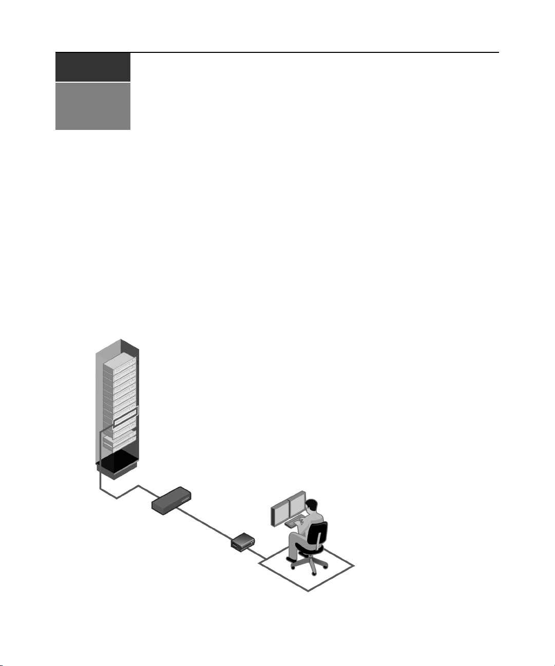
The Avocent LongView® IP KVM extender enables the desktop user to have full access to
keyboard, video, mouse (KVM) and audio devices. The LongView IP KVM extender provides
users with a full workstation experience from anywhere on the corporate TCP/IP network, while
maintaining the workstations securely housed in a corporate data center.
The LongView IP KVM extender consists of:
• A transmitter to connect externally to the remote workstation
• A receiver located at the user’s desk
1
Rack Mounted
Servers and Blades
User 1
Figure 1.1: LongView IP KVM Extender - Basic System
Gigabit Ethernet
Switch
LongView IP
Receiver
User 1
Page 12

2 LongView IP KVM Extender Installer/User Guide
Automatic connection
When the receiver is turned on, a connection is automatically established with the remote
workstation via the transmitter.
Ethernet addressing
The receiver and transmitter are IP-addressable devices that locate workstations anywhere within
the network and at any distance from desktop users. The transmitter uses standard network
protocols to transfer data streams between the remote workstation and the peripheral devices
located at the receiver. The LongView IP KVM extender can operate on a network connection of
100 Mbps or 1 Gbps. For optimum performance, a 1 Gbps connection is recommended.
Multiplatform support
The transmitter is connected to the remote workstation via USB connectors. This enables the
LongView IP KVM extender to work seamlessly with PC, Sun and Macintosh workstations. The
LongView IP KVM extender supports the following operating systems:
•Microsoft® Windows®
•Red Hat Linux®
•Solaris
TM
• Mac OS®
Security
The LongView IP KVM extender supports Secure Sockets Layer (SSL) over a TCP/IP connection .
All data transmitted between the receiver and the transmitter is encrypted. Password protection is
also provided to control access to all administration functions.
Administration and maintenance
The receiver incorporates a serial menu that allows you to perf orm administr ation and maintenance
tasks for both the receiver and the transmitter. Examples of tasks you can perform include
configuration of network settings and firmware Flash upgrades.
Flash upgradable
Upgrade your firmware at any time using the XMODEM or HTTP protocols to ensure that your
LongView IP KVM transmitter and receiver are always running the most current version available.
Support for keyboards and mice
USB and PS/2 keyboards and mice are fully supported by the LongView IP KVM extender. The
system also allows for mix and match of USB and PS/2 peripherals. For example, it is possible to
use a USB keyboard in conjunction with a PS/2 mouse. The defa ult keybo ard and mouse driv ers of
the remote workstation are fully supported. This enables the LongView IP KVM extender to
support 2-, 3- and 5-button mice with scroll- and tilt-wheel capability. Composite mouse and
keyboard devices are also supported.
Page 13

USB support
The LongView IP KVM extender is compatible with the USB 2.0 standard. The receiver provides
four USB 2.0 compliant ports that can be used to access USB keyboards, mice and USB hubs. Hotplugging of USB devices is supported.
NOTE: A hub cannot be used to expand the number of USB ports available.
Audio
The LongView IP KVM extender supports CD-quality stereo from the remote workstation to
peripheral speakers, and mono-quality audio from a microphone to the remote workstation.
Video
Video of 24-bit color depth up to a resolution of 1280 x 1024 at 60 Hz is supported by the
LongView IP KVM extender. Both CRT and flat-panel LCD monitors are supported, and can be
connected to the LongView IP KVM extender via a DVI-I video connector. VGA monitors can be
attached to the system by using a DVI to VGA adaptor. The system supports DDC version 2B.
Safety Precautions
To avoid potential vide o and/or keyb oard problems when using A vocent products:
• If the building has 3-phase AC power, ensure that the server and monitor are on the same
phase. For best results, they should be on the same circuit.
Chapter 1: Product Overview 3
To avoid potentially fatal shock hazard and possible damage to equipment, please observe the
following precautions:
• Do not use a 2-wire extension cord in any Avocent product configuration.
• Test AC outlets at the server and monitor for proper polarity and grounding.
• Use only with grounded outlets at both the workstation and monitor. When using a backup
Uninterruptible Power Supply (UPS), power both the workstation and the transmitter off the
same supply.
NOTE: The AC inlet is the main disconnect.
Page 14

4 LongView IP KVM Extender Installer/User Guide
Page 15

CHAPTER
Installation
2
Getting Started
Before installing your LongView IP KVM extender, refer to the list below to ensure that you have
all the items necessary for installation.
Items needed to install the LongView IP KVM extender
• Receiver
•Transmitter
• External power supply for the receiver
• IEC power cord
• LongView IP KVM Extender Quick Installation Guide
• UTP cable (not supplied)
• Three-wire serial cable or null modem cable (not supplied)
5
Optional items
To power the transmitter if a remote workstation does not have two available USB ports:
• A power supply (contact Avocent more details)
To connect a VGA monitor to the receiver:
• A DVI to VGA adaptor (not supplied)
To connect the transmitter to a remote workstation that has VGA video output:
• A VGA to DVI-I adaptor (not supplied)
To connect the transmitter to a remote workstation that has DVI-D video output:
• A DVI-D to DVI-I adaptor (not supplied)
Mounting Option
The receiver mounts to either the rear of a flat-panel monitor via a mounting plate accessory
(ordered separately) or is desk-mountable via a mounting kit, also available from Avocent.
Page 16
6 LongView IP KVM Extender Installer/User Guide
Installation Options
CAUTION: To reduce the risk of electric shock or damage to your equipment, disconnect the power from the
receiver by unplugging the power supply from the electrical outlet. Also, turn on the remote workstation and the
receiver in the order described in the following procedures.
You can install the LongView IP KVM extender by using either the point-to-point method or
through a network.
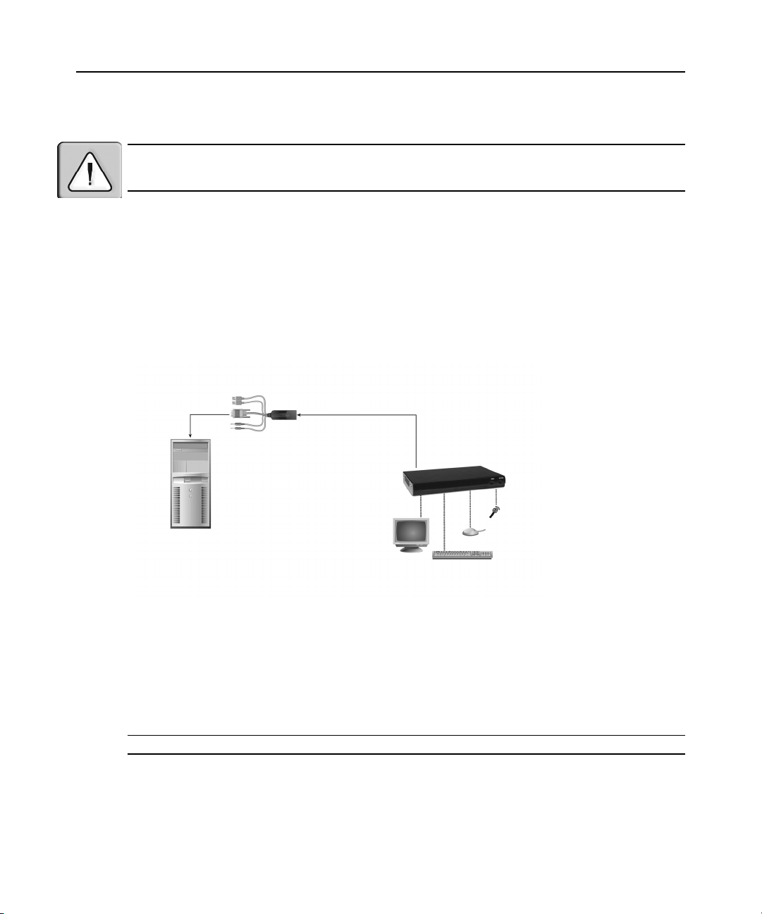
Point-to-point installation
The following instructions will enable you to install your LongView IP KVM extender in a pointto-point configuration. In a point-to-point configuration, no administrator set up of the transmitter
or the receiver is required. However, if you choose the point-to-point configuration you can install
only one transmitter and receiver pair on a subnet.
Transmitter
Receiver
Remote
Workstation
Figure 2.1: Point-to-point Installation
To connect the transmitter:
Before connecting the transmitter to the remote workstation, ensure that the reso lution and the
refresh rate of the remote workstation are supported by the LongView IP KVM extender system.
Set the screen resolution and refresh rate of the remote workstation according to the receiver video
resolutions listed in Appendix A. Unsupported settings will cau se blank video at the receiver.
NOTE: Go to www.avocent.com for updated information on supported resolutions and refresh rates.
1. Turn off the remote workstation.
2. The transmitter has two USB connectors. Connect each of these connectors to a corresponding
USB port on the remote workstation.
Page 17
Chapter 2: Installation 7
Microphone
3. Connect the video connector on the tr ans mitter to the app ropriately lab eled p ort o n the back of
the workstation.
NOTE: A VGA-only workstation can be connected to the transmitter using a VGA to DVI-I adaptor. You must
configure the transmitter video settings for VGA through the serial menu. For more information, see
Video Input Settings on page 18.
Configuring
4. Connect the transmitter’s audio and microphone connectors to the appropriately labeled ports
on the back of the workstation.
NOTE: For CD-quality audio, you must configure the Transmitter and the Receiver using the serial menu. For
more information, see Audio Performance Settings on page 26.
5. Connect one end of the UTP cable to the transmitter’s RJ-45 connector.
6. Turn on the workstation.
7. Route the other end of the UTP cable to the location you have chosen for the receiver. If
necessary, you can extend the UTP cable via junctions or a hub (subject to normal Ethernet
cabling practices).
The transmitter draws electrical power from two USB ports on the remote workstation. One USB
port is not sufficient to turn on the transmitter. If you have only one USB port on your remote
workstation, you will need to order an external power supply for the transmitter from Avocen t.
Receiver
Speakers
External
Power
Supply
Remote
Workstation
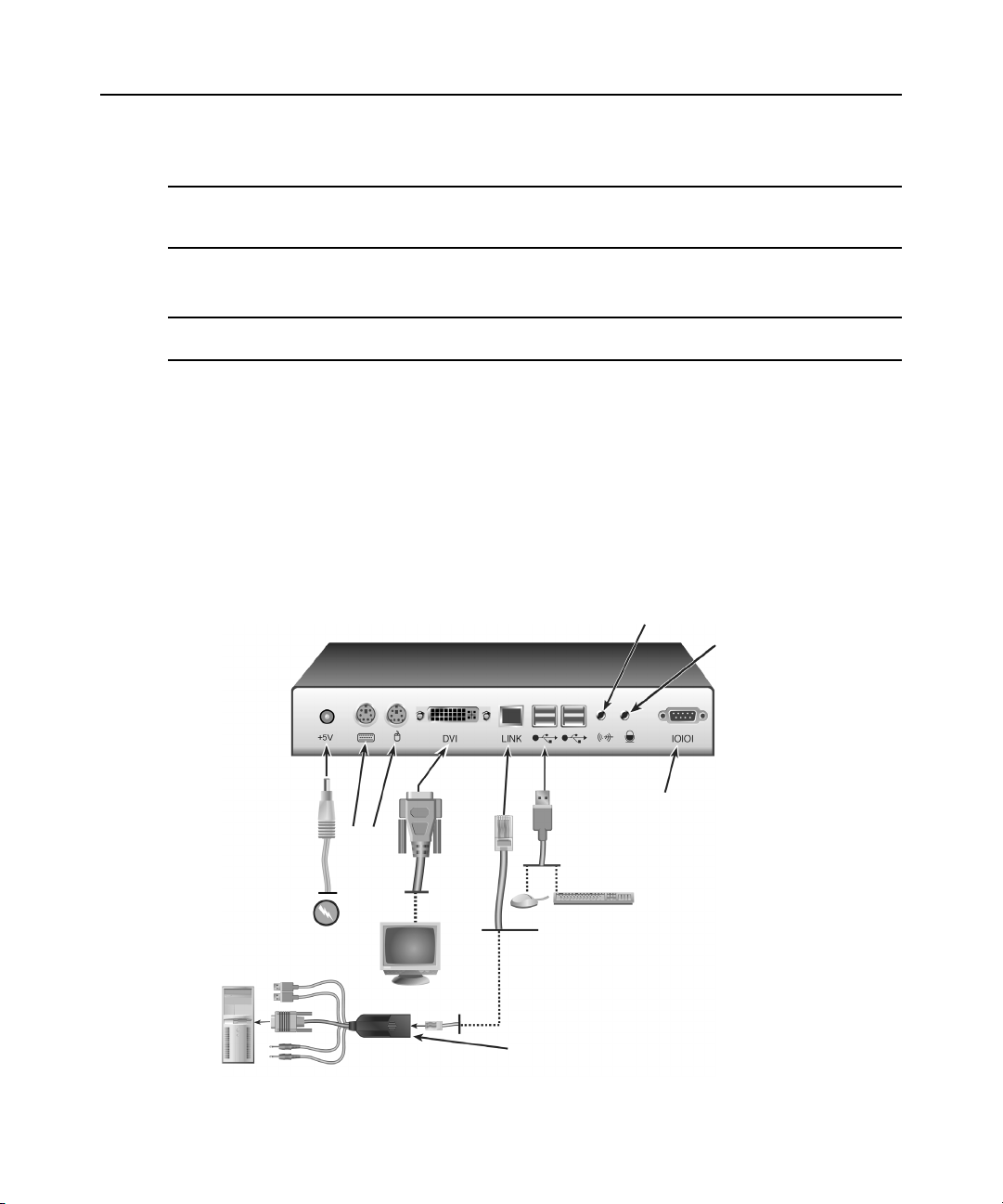
Figure 2.2: Receiver and Transmitter Installation
PS/2
Serial
Local Peripherals
Attached via USB
Transmitter
Page 18
8 LongView IP KVM Extender Installer/User Guide
Connecting power
To connect the receiver:
1. Connect your keyboard, monitor, mouse and other peripheral cables to the appropriately
labeled ports on the back of the receiver.
2. Connect the UTP cable from the transmitter to the RJ-45 port on the back of the receiver.
NOTE: Use only the power supply provided by Avocent.
3. Connect one end of the 2.5 mm connector on the receiver’s power supply into the DC power
jack on the receiver. Connect the other end to an appropriate power source.
4. Turn on the receiver. A connection will be established with the remote workstation.
NOTE: VGA monitors can be connected to the receiver by using a DVI-I to VGA adaptor.
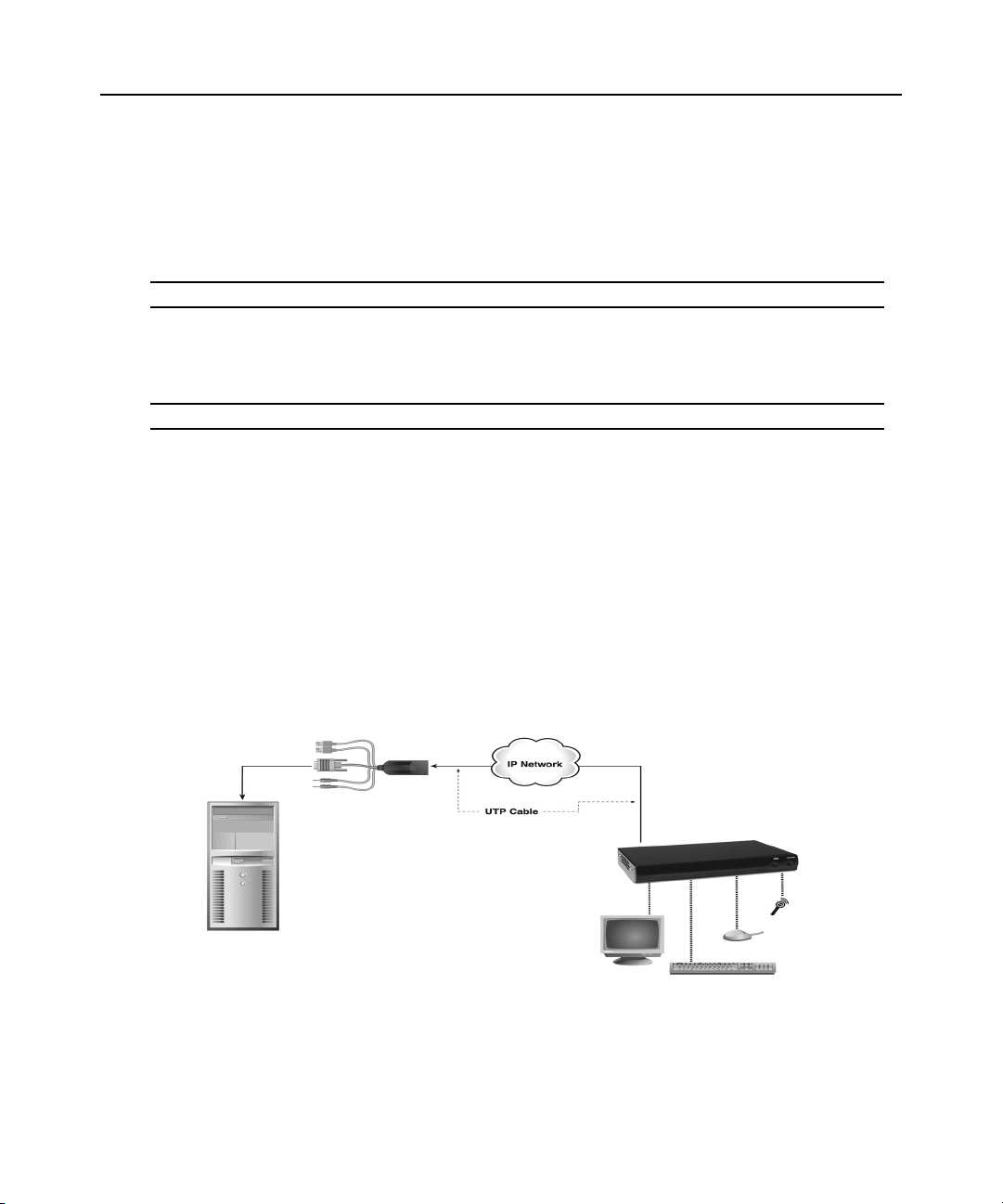
Networked inst all at ion
The following instructions will enable you to install your LongView IP KVM extender in a
networked configuration. In this installation, multiple transmitters and receivers are attached via
the same Ethernet network. In this case, it is important for each u nit to be con figu red with a uniq ue
IP address.
Transmitters and receivers may be configured for use on a single subnet or for use across routers.
Use of routers, however, will cause a slight increase in end-to-end latencies, which may not be
acceptable for all applications.
Transmitter
Remote Workstation
Figure 2.3: Networked Installation
Receiver
Page 19

Chapter 2: Installation 9
The LongView IP KVM extender has been pre- confi gured with factory-defa ult network set tings. If
you install multiple extenders on the same subnet, you will need to assign a unique IP address to
each extender via the serial port.
Table 2.1: Default Network Settings
Default
Component IP Address Type
Receiver 192.168.13.1 static 0.0.0.0 255.255.255.0
Transmitter 192.168.13.2 static 0.0.0.0 255.255.255.0
Gateway
Subnet Mask
To install the LongView IP KVM extender on a network:
1. Connect the transmitter to the remote workstation as described previously in Point-to-point
installation on page 6. Connect one end of the UTP cable to the transmitter’s RJ-45 connector
and the other end to the Ethernet network.
2. Connect the receiver to the peripherals as described above in Point-to-point installation on
page 6. Use a length of UTP cable to connect the receiver to the Ethernet network via the RJ45 connector on the rear of the receiver.
3. Turn on the receiver.
4. Use the serial menu to re-configure the network settings for the transmitter an d then the
receiver. See
Configuring Network Settings on page 13 for more information.
NOTE: If the receiver and transmitter are to be located on different subnets, configure their network settings
before you connect to the network. If there are already transmitter/receiver pairs operating on the subnet,
configure network settings of new transmitter/receiver pairs before connecting them to the network.
5. Repeat this procedure for each transmitter and receiver pair you wish to install on the network.
Page 20

10 LongView IP KVM Extender Installer/User Guide
Page 21

CHAPTER
Operations
3
Overview
Operating a remote workstation through the LongView IP KVM extender is no different than
working directly connected to your workstation. When you turn on the receiver, a connection is
automatically established with the workstation.
While the default settings of your LongView IP KVM extender will work with most system s, you
may choose to change settings to better fit your system.You can change internal settings and
upgrade the LongView KVM IP extender via the serial menu.
LED identification
Front panel
11
There are two blue LEDs on the front panel of the receiver. The PWR LED will light up when the
receiver has been turned on. The ACTIVE LED will blink slowly until the receiver establishes a
connection with the transmitter. When a connection has been established between the receiver and
the transmitter, the ACTIVE LED will stop blinking and will remain lit.
Rear panel
Two LEDs are built into the RJ-45 connectors on the rear of the receiver and transmitter. The
following table illustrates their operation.
Table 3.1: RJ-45 Connector LEDs
LED Indication Meaning
LED 1 Green static Linked at 1 Gbps
Green flashing Linked at 100 Mbps
Green off No Link
LED 2 Yellow static Linked but no activity
Yellow flashing Transmit/receive activity
Page 22

12 LongView IP KVM Extender Installer/User Guide
Accessing the System
When the receiver is turned on, it will initiate a connection with the remote workstation.
NOTE: If the remote workstation has been turned off, the receiver cannot establish a connection.
The Serial Menu
The receiver incorporates a serial menu that allows you to:
• Configure network settings for the receiver and transmitter
• Set or change passwords
• Upgrade your firmware for the receiver and transmitter
• Reset to factory defaults
• Set a session time-out value
• Change the audio performance settings
Accessing the serial menu
You can access the serial menu via the serial port on the back of the receiver. All terminal
commands are executed through a terminal or P C running terminal emulation software. By default,
two passwords are required to access the LongView IP KVM extender via the receiver. One
password is for the receiver; the other password is for the transmitter. In both cases, the default
password is password. For information on how to change the default password, see
Authentication on page 20.
Items needed to access the serial menu
• Networked workstation with a serial port
• Null modem serial cable (male DB-9) or three-wire serial cable
• Terminal emulation software
To access the serial menu:
1. Connect one end of the serial cable to the serial port on the back of the receiver.
2. Connect the other end of the serial cable to the serial port of your PC.
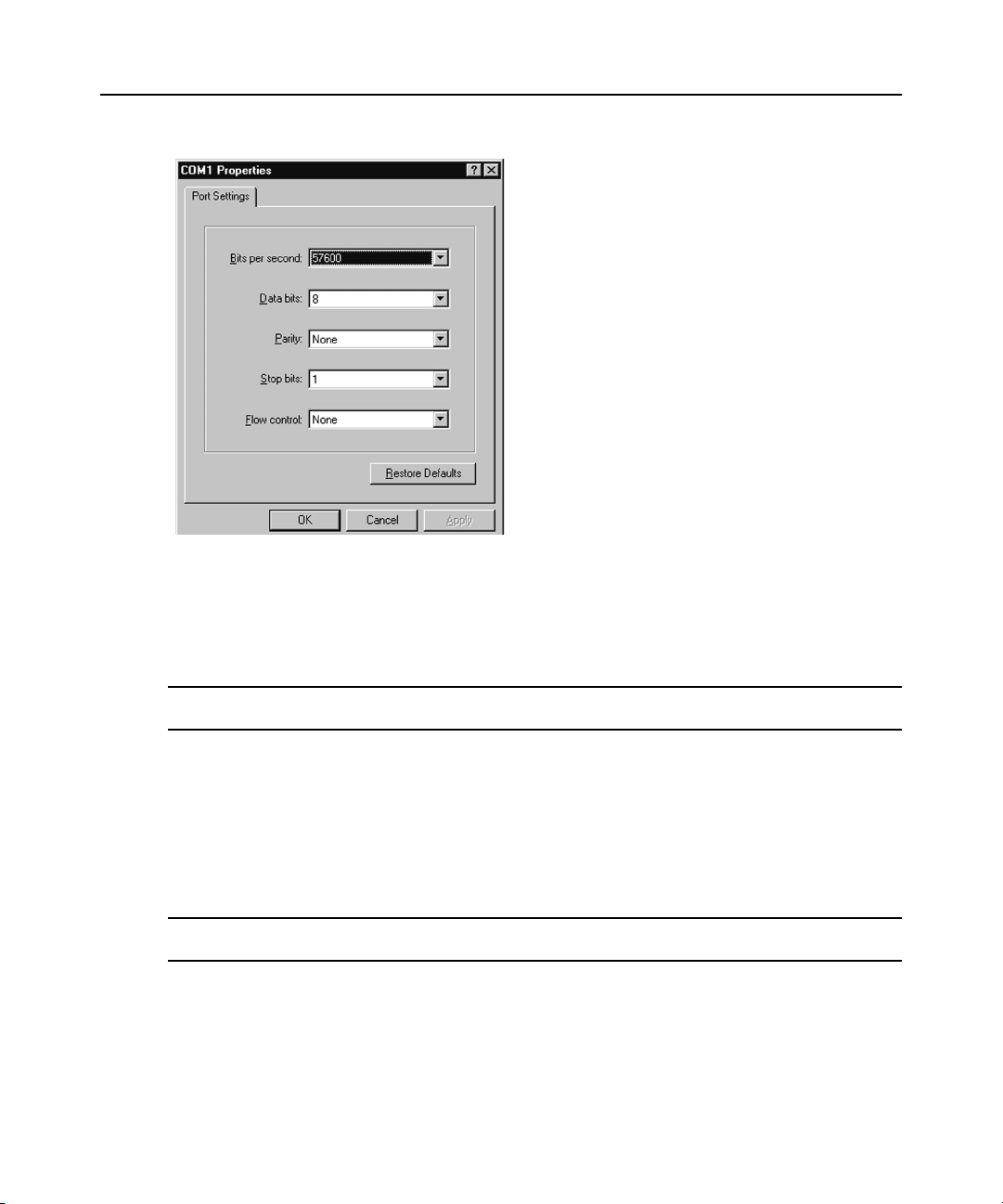
3. Launch your terminal emulation software . The Com1 Properties menu will appear.
4. Configure the terminal session for 57600 bits per second, 8 data bits, no parity, 1 stop bit and
no flow con trol. Click OK.
NOTE: Software (XON/XOFF) flow control is supported. However, it should not be used when using XMODEM.
Page 23
Chapter 3: Operations 13
Figure 3.1: Com1 Properties Menu
5. Press Enter to display the serial menu. The Appliance Selection Menu will appear.
6. Type 1 to enter the Receiver Menu or type 2 to to enter the Transmitter Menu. You will be
prompted to enter a password.
7. Type the password an d press Enter.
NOTE: If there is no transmitter connected to the receiver , an error message will display and you will be returned
to the Appliance Selection Menu.
Navigating the serial menu
To navigate the serial menu, type the number or letter that corresponds to the option you wish and
press
Enter. To exit a menu or screen and to confirm any configuration changes you have made,
type
0 (zero) and press Enter.
Configuring Network Settings
NOTE: It is recommended that you configure the network settings for the transmitter before you configure the
network settings for the receiver. Static addressing is the only IP addressing method supported.
Page 24
14 LongView IP KVM Extender Installer/User Guide
To configure network settings for the transmitter:
1. Activate the serial menu as described in Accessing the serial menu on page 12.
2. Choose option 2 to access the Transmitter Menu and press Enter. If the password option is
enabled, you will be prompted for a password.
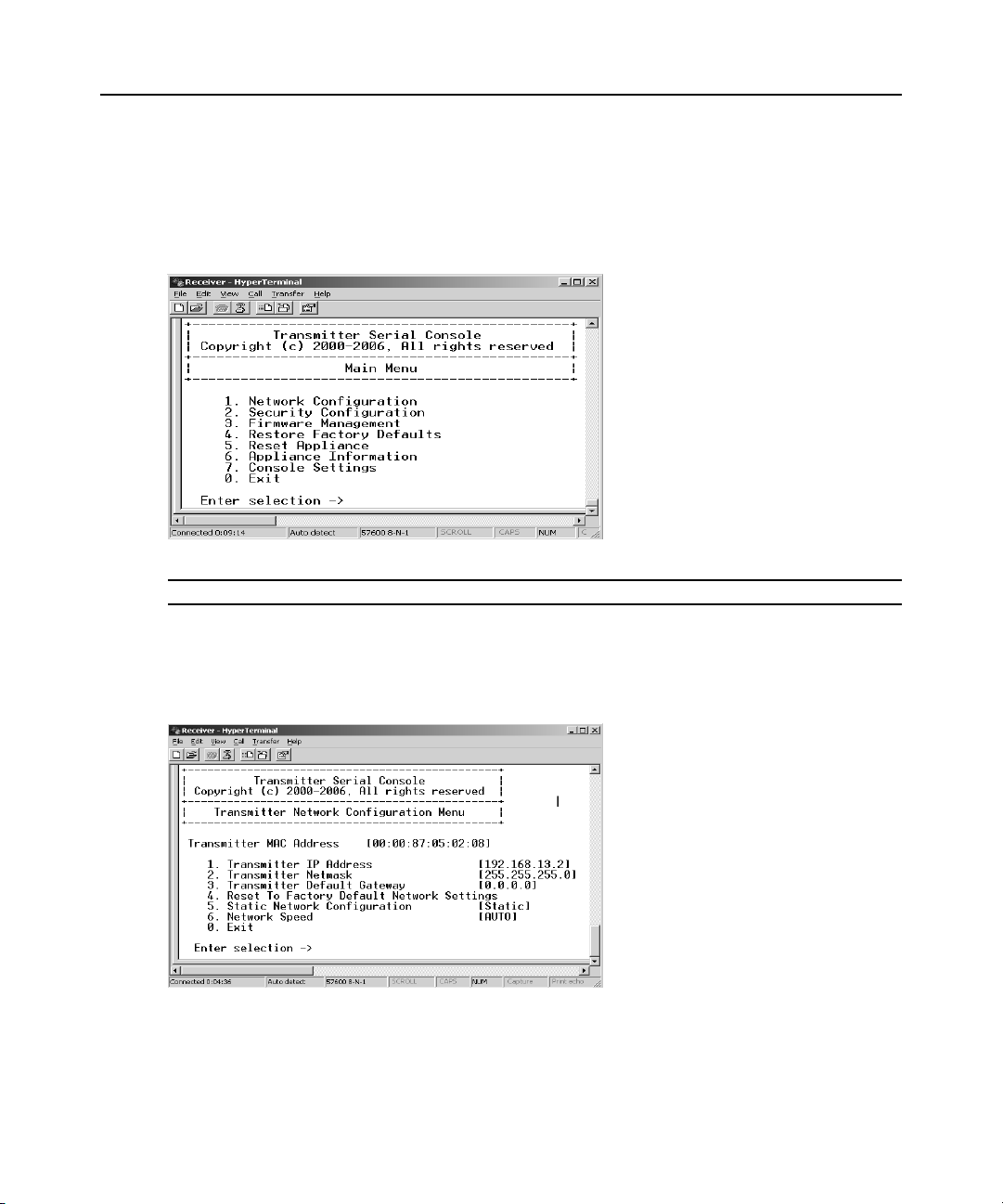
3. Type the password an d press Enter. The Transmitter Main Menu will appear.
Figure 3.2: Transmitter Main Menu
NOTE: The Reset Appliance option in the Transmitter Main Menu applies only to network settings.
4. Press 1 to select the Network Configuration option and press Enter. The Network
Configuration Menu appears.
5. Press 1 to select the Transmitter Network Config option and press Enter. The Transmitter
Network Configuration Menu will appear.
Figure 3.3: Transmitter Network Configuration Menu
6. Press 1 to select the Transmitter IP Address option and press Enter. Type a valid IP address.
Press
Enter to return to the Transmitter Network Configuration Menu.
7. Configure the network and default network using the same principle.
Page 25
Chapter 3: Operations 15
8. Type 0 (zero) and press Enter to return to the Network Configuration Menu, or if you made a
mistake and do not wish to save changes to the network settings, type
C and press Enter.
9. To confirm your changes and apply those settings type 0 (zero) and press Enter.
10. A system message will appear that states Connection to the transmitter is lost. You will be
automatically returned to the Appliance Selection Menu
screen.
11. Choose option 1 to access the Receiver Menu. If the password option is enabled, you will be
prompted f or a password.
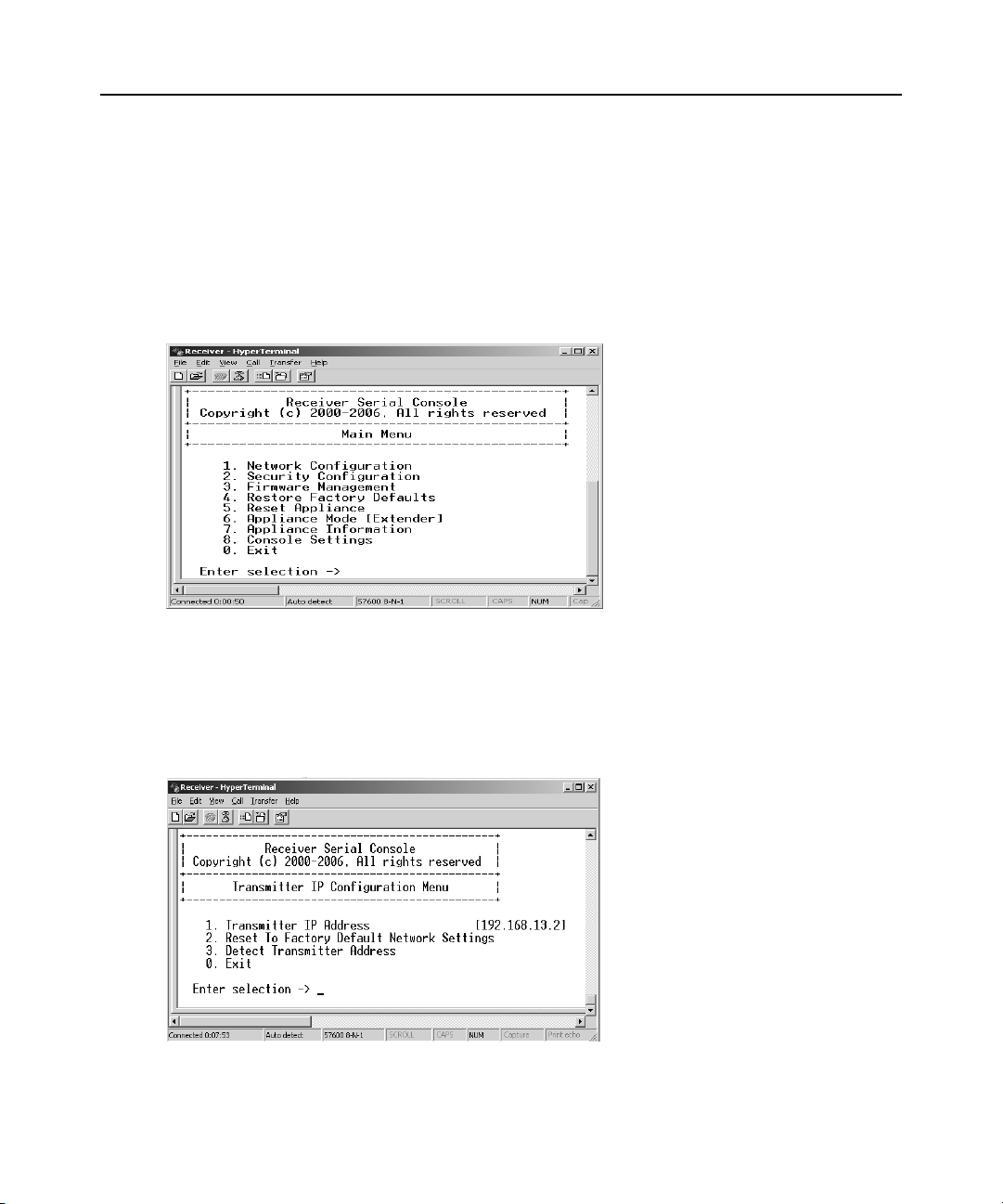
12. Type the password a nd press Enter. The Receiver Main Menu will appear.
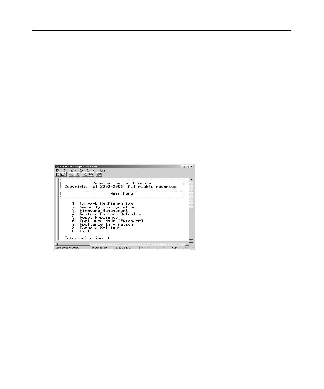
Figure 3.4: Receiver Main Menu
13. Press 1 to select Network Configuation option and press Enter. The Network Configuration
Menu will appear.
14. Press 1 to select the Transmitter IP Config option and press Enter. The Transmitter IP
Configuration Menu will appear. The old transmitter IP address is displayed beside menu
option 1.
Figure 3.5: Transmitter Configuration Menu on the Receiver
Page 26
16 LongView IP KVM Extender Installer/User Guide
15. Press 1 to select Transmitter IP Address and press Enter. Type the new IP address for the
transmitter. Press
Enter to return to the Transmitter IP Configuration Menu.
16. Type 0 (zero) and press Enter to return to the Network Configuration Menu.
17. If you made a mistake and do not wish to save the changes you made to the network settings
type
C and press Enter.
18. To confirm your changes and apply those settings, type 0 (zero) and press Enter.
19. The receiver will now automatically reset to apply the new network configuration. Y ou will be
automatically returned to the Appliance Selection Menu screen. The connection to the
transmitter will be automatically restored.
To configure network settings for the receiver:
1. Activate the serial menu as described in Accessing the serial menu on page 12.
2. Press 1 to access the Receiver Menu and press Enter. If the password option is enabled, you
will be prompted for a password. See
3. Type the password an d press Enter. The Receiver Main Menu will appear.
Authentication on page 20.
Figure 3.6: Receiver Main Menu
Page 27
Chapter 3: Operations 17
4. Press 1 to select Network Configuration and press Enter. The Network Configuration Menu
will appear.
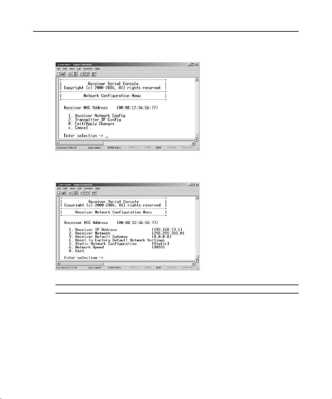
Figure 3.7: Network Configuration Menu
5. Press 1 to select Receiver Network Config and press Enter. The Receiver Network
Configuration Menu will appear and display the current network settings.
Figure 3.8: Receiver Network Configuration Menu
NOTE: The Reset option in the receiver Network Configuration Menu applies only to network settings.
6. Press 1 to select Receiver IP Address and press Enter.
7. Type a valid IP address. Press Enter to return to the Receiver Network Configuration Menu.
8. Press 2 to select Receiver Netmask and press Enter.
9. Type a valid receiver netmask. Press Enter to return to the Receiver Network
Configuration Menu.
10. Press 3 to select Receiver Default Gateway and press Enter.
Page 28
18 LongView IP KVM Extender Installer/User Guide
11. Type a valid receiver default gateway. Press Enter to return to the Receiver Network
Configuration Menu.
12. Type 0 (zero) and press Enter to return to the Network Configuration Menu.
13. If you made a mistake and do not wish to save the changes you made to the network settings,
type
C and press Enter.
14. To confirm your changes and apply those settings, type 0 (zero) and press Enter.
NOTE: Changes to network configurations are applied only after you exit the Network Configuration Menu.
15. The receiver will now automatically reset to apply the new network configuration. During
reset, the receiver will drop its connection to the transmitter. You will be automatically
returned to the Appliance Selection Menu. The connection will be restored.
Configuring Video Input Settings
The LongView IP KVM extender system is capable of transmitting either digital (DVI) or analog
video (VGA) from the remote workstation to your monitor. To enable the system to transm it the
appropriate video signal for your monitor, you must first configure the video input settings for
the transmitter.
NOTE: Video-display problems may occur if video input settings are not configured correctly.
To configure the video input settings:
1. Activate the serial menu as described in Accessing the serial menu on page 12.
2. Choose option 2 to access the Transmitter Menu and press Enter. If the password option is
enabled, you will be prompted for a password. See
Authentication on page 20 .
3. Type the password an d press Enter. The Transmitter Main Menu will appear.
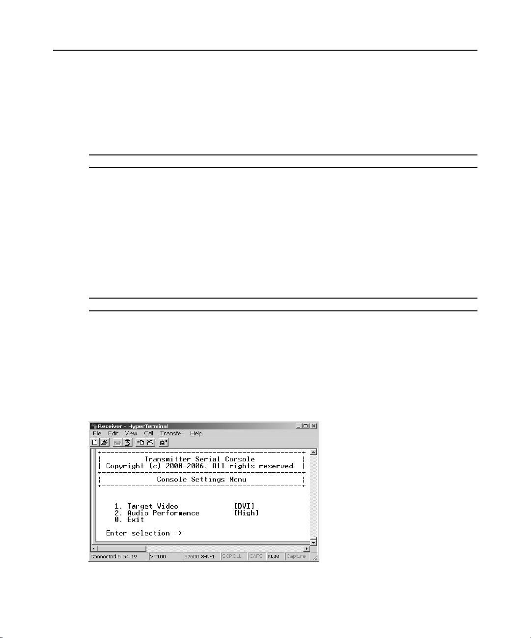
4. Press 7 to select Console Settings and press Enter. The Console Settings Menu will appear.
The current video input setting is displayed beside the Target Video option.
Figure 3.9: Transmitter Console Settings Menu
Page 29
Chapter 3: Operations 19
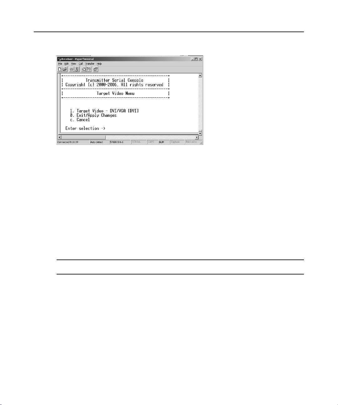
5. Press 1 to select Target Video and press Enter. The Target Video Menu will display.
Figure 3.10: Transmitter Target Video Menu
6. To toggle between DVI or VGA, press 1 to select the Target Video - DVI/VGA option and
press
Enter.
7. The updated setting will then be displayed beside menu option 1.
8. To save your changes and exit the menu, type 0 (zero) and press Enter. The unit resets after
you press
Enter.
Detecting a Transmitter IP Address
In the event that you forget the IP address of a transmitter, you can use the serial menu to detect the
IP address of a transmitter that is connected to the receiver.
T o detect the IP address of a connected transmitter:
1. Turn off the remote workstation to which the transmitter is attached.
NOTE: If the transmitter receives its power from an external power supply, disconnect the transmitter from that
external power supply.
2. Press 1 to select the Receiver Menu and press Enter. If the password option is enabled, you
will be prompted for a password. See
3. Type the password an d press Enter. The Receiver Main Menu will appear.
4. Press 1 to select Network Configuration and press Enter. The Network Configuration Menu
will appear.
5. Press 2 to select Transmitter IP Config and press Enter. The Transmitter IP Config Menu will
appear. The old transmitter IP address is displayed beside menu option 1.
6. Press 3 to select Detect Transmitter Address and press Enter. The following message will be
displayed: Connect the transmitter and the receiver, then power up the transmitter.
7. Turn on the transmitter.
Authentication on page 20.
Page 30
20 LongView IP KVM Extender Installer/User Guide
8. The receiver will detect the IP address of the connected transmitter. The Transmitter IP
Configuration Menu will refresh and the current IP address of the connected transmitter will be
displayed beside menu option 1.
NOTE: The detected IP address of the connected transmitter will not be automatically saved. You must enter the
detected IP address manually, by choosing Transmitter IP Address from the Transmitter IP Configuration Menu.
Authentication
Two passwords are required to access the LongView IP KVM extender via the serial menu. One
password is for access to the serial menus that control the receiver. The other password is for access
to the serial menus that control the transmitter. In both cases, the default passwor d is password.
Authentication for the receiver
You can change the password settings for the receiver through the serial menu via the Receiver
Security Configuration Menu.
T o access the Receiver Security Configuration Menu:
1. Activate the serial menu as described in Accessing the serial menu on page 12.
2. Choose option 1 to access the Receiver Menu. If the password option is enabled, you will be
prompted for a password. See
3. Type the password an d press Enter. The Receiver Main Menu will appear.
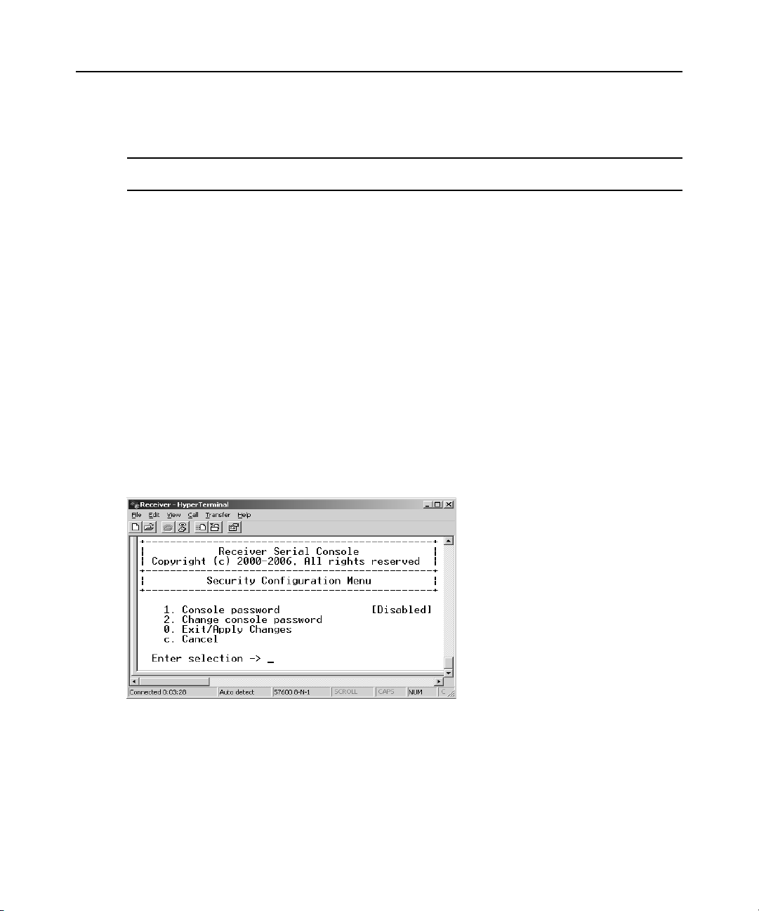
4. Choose Security Configuration. The Security Configuration Menu will appear.
Authentication on page 20.
Figure 3.11: Receiver Security Configuration Menu
T o disable or enable the receiver password:
1. Press 1 to select Console Password on the Security Configuration Menu and press Enter. If a
password had been enabled, this action will disable the password.
2. If a password had been disabled, you will be prompted to enter a password.
3. Type the new password and press Enter.
Page 31

Chapter 3: Operations 21
NOTE: Each password must consist of ASCII characters and contain between 6 and 64 characters.
4. Confirm the new password. If successful, yo u will see a mes sa ge st ating that the pas sword has
been changed.
5. Press Enter.
6. To save your changes and exit the menu, type 0 (zero) and press Enter.
To change the receiver password:
1. Press 2 to select Change Console Password on the Security Configuration Menu and press
Enter. You will be prompted to enter your current password.
2. T y pe your current pas sword and pres s Enter. You will be prompted to enter the new password.
3. Type the new password and press Enter.
NOTE: Each password must consist of ASCII characters and contain between 6 and 64 characters.
4. Confirm the new password. If successful, yo u will see a mes sa ge st ating that the pas sword has
been changed.
5. Press Enter.
6. To save your changes and exit the menu, type 0 (zero) and press Enter.
To reset t he receiver or transmitter password:
If you lose your receiver or transmitter password, you can reset the system to the default password
with the help of Avocent Technical Support.
1. Access the serial menu as described in Accessing the serial menu on page 12.
2. Choose option 1 to access the Receiver Menu or option 2 to access the Transmitter Menu and
press
Enter.
3. You will be pr ompted to enter your current password. Type ?????? (six question marks) and
press
Enter. The serial menu will also prompt you to enter a key.
4. Contact Avocent Technical Support to obtain the key. The Technical Support Specialist will
ask you for the 16 character hex code. Read out the code exactly as it appears on the serial
menu. The Specialist will provide you with a new 16 character hex sequence.
5. In the serial menu at the Key prompt, type the 16 character hex sequence provided to you by
Avocent Technical Support. Press
Enter.
6. The default password is now active.
Authentication for the transmitter
You can change the password settings for the transmitter through the serial menu using the
Transmitter Security Configuration Menu.
T o access the Transmitter Security Configuration Menu:
1. Activate the serial menu as described in Accessing the serial menu on page 12.
Page 32

22 LongView IP KVM Extender Installer/User Guide
2. Choose option 2 to access the Transmitter Menu and press Enter. If the password option is
enabled, you will be prompted for a password. See
3. Type the password an d press Enter. The Transmitter Main Menu will appear.
4. Press 2 to select Security Configuration and press Enter. The Security Configuration Menu
will appear.
Figure 3.12: Transmitter Security Configuration Menu
T o disable or enable the transmitter password:
1. Press 1 to select Console Password on the Security Configuration Menu and press Enter. If a
password has been enabled, this action will disable the password.
2. If a password has been disabled, you will be prompted to enter a password.
3. Type the new password and press Enter.
Authentication on page 20 .
NOTE: Each password must consist of ASCII characters and contain between 6 and 64 characters.
4. Confirm the new password. If successful, yo u will see a mes sa ge st ating that the pas sword has
been changed.
5. Press Enter.
6. To save your changes and exit the menu, type 0 (zero) and press Enter.
To change the transmitter password:
1. Press 2 to select Change Console Password on the Security Configuration Menu and press
Enter. You will be prompted to enter your current password.
2. T y pe your current pas sword and pres s Enter. You will be prompted to enter the new password.
3. Type the new password and press Enter.
NOTE: Each password must consist of ASCII characters and contain between 6 and 64 characters.
4. Confirm the new password. If successful, yo u will see a mes sa ge st ating that the pas sword has
been changed.
Page 33

5. Press Enter.
6. To confirm the new password and exit the screen, type 0 (zero) and press Enter.
Flash Upgrading the LongView IP KVM Extender
NOTE: It is recommended that you Flash upgrade the transmitter before you Flash upgrade the receiver.
You can Flash upgrade your receiver and transmitter using either XMODEM or HTTP. The
receiver and transmitter are upgraded separately using individual upgrade files supplied by
Avocent. For optimum system performance, keep your firmware versions current.
NOTE: Do not use software (XON/XOFF) flow control when using XMODEM.
To Flash upgrade your transmitter or receiver using XMODEM:
1. Download the transmitter upgrade file from Avocent.
2. Activate the serial menu as described in Accessing the serial menu on page 12.
3. Choose option 1 to access the Receiver Menu or option 2 to access the Transmitter Menu. If
the password option is enabled, you will be prompted for a password.
4. Type the password an d press Enter. The Transmitter Main Menu will appear.
5. Press 3 to select Firmware Management and press Enter. The Firmware Management Menu
will appear.
6. Choose the Flash Upgrade Via XMODEM option and press Enter.
7. Specify the location of the upgrade file and initiate the file transfer.
8. When the transfer has completed, a message will display stating Firmware update successful.
Resetting Appliance... During reset, the transmitter will drop the connection to the receiver. A
second system message will appear that states: Connection to the transmitter is lost. You will
be automatically returned to the Appliance Selection Menu.
Chapter 3: Operations 23
NOTE: If the transmitter or receiver determines that the upgrade file is invalid, the transmitter cancels the
upgrade and maintains the previous firmware version. A message appears indicating that the upgrade has failed.
Page 34

24 LongView IP KVM Extender Installer/User Guide
Restoring Factory Default Settings
The serial menu enables you to easily restore the factory default settings of both the receiver and
the transmitter. To view a full list of the factory default settings, see
page 33.
NOTE: Restoring factory default settings will also reset network settings. Before restoring factory default
settings, assess whether this is likely to c ause conf licts with other devices on the network.
To restore the transmitter or receiver factory default settings:
1. Activate the serial menu as described in Accessing the serial menu on page 12.
2. Choose option 1 to access the Receiver Menu or option 2 to access the the Transmitter Menu.
If the password option is enabled, you will be prompted for a password.
3. Type the password an d press Enter.
4. Press 4 to select Restore Factory Defaults and press Enter.
5. The receiver will now automatically reset. Y ou will be automatically returned to the Appliance
Selection Menu.
6. During reset, the receiver will drop the connection to the transmitter. When reset is complete,
the receiver will restore the connection to the transmitter using the new settings.
Factory Default Settings on
Resetting the LongView IP KVM Extender
To reset the receiver or transmitter :
1. Activate the serial menu as described in Accessing the serial menu on page 12.
2. Choose option 1 to access the Receiver Menu or option 2 to access the Transmitter Menu. If
the password option is enabled, you will be prompted for a password.
3. The Receiver Main Menu will appear.
4. Press 5 to select Reset Appliance and press Enter. The Reset Appliance Menu will appear.
Figure 3.13: Receiver Reset Appliance Menu
Page 35

5. Press 1 to select Receiver Reset and press Enter to initiate the reset. A Restting appliance
message will be displayed on the serial menu. During reset, the connection to the transmitter is
dropped. When the reset is complete, you will be automatically returned to the Appliance
Selection Menu. The connection to the transmitter will be automatically restored.
To reset the transmitter:
1. Activate the serial menu as described in Accessing the serial menu on page 12.
2. Choose option 2 to access the Transmitter Menu. If the password optio n is enabled, you will be
prompted for a password. See
3. The Transmitter Main Menu will appear.
4. Press 5 to select Reset Appliance and press Enter. The Reset Appliance Menu will appear.
5. Press 1 to select Transmitter Reset and press Enter to initiate the reset. A Restting appliance
message will be displayed on the serial menu. During reset, the transmitter will drop the
connection to the receiver. A second system message will appear that states: Connection to the
transmitter is lost. You will be automatically returned to the Appliance Selection Menu. The
connection will be automatically restored.
Authentication on page 20.
Viewing System Information
The serial menu enables you to display the firmware release and details of the receiver and of
the transmitter.
Chapter 3: Operations 25
T o view system information:
1. Activate the serial menu as described in Accessing the serial menu on page 12.
2. Choose option 1 to access the Receiver Menu or option 2 to access the Transmitter Menu. If
the password option is enabled, you will be prompted for a password.
3. Type the password an d press Enter. The Receiver Main Menu will appear.
4. Press 6 to select Appliance Information and press Enter. The Appliance Information Menu
will appear.
The Appliance Information Menu cont ains the following info rmation: receiver nam e; EID number;
release version; appli cation; boo t and FP GA firmware version number s; and the manuf acturing pa rt
number. All values are read-only.
Session Retry Settings
The LongView IP KVM extender is designed to automatically establish a connection between the
receiver and the remote workstation. By default, if the receiver cannot immediately establish a
connection with the remote workstation it will retry once per second until a connection is
successfully established. You can change the default session retry settings using the serial menu.
T o access the Session Retry Menu:
1. Activate the serial menu as described in Accessing the serial menu on page 12.
Page 36

26 LongView IP KVM Extender Installer/User Guide
2. Choose option 1 to access the Receiver Menu and enter the password if necessary. The
Receiver Main Menu will appear.
3. Press 8 to select Console Settings and press Enter. The Console Settings Menu will appear.
4. Enter the number corresponding with Session Retry and press Enter. The Session Retry Menu
will appear.
Figure 3.14: Session Retry Menu
T o change the retry settings:
1. Access the Session Retry Menu via the serial menu as described in the previous procedure.
2. T o change the time interval between retry attempts, press 1 to select the Session Retry Timeou t
Seconds otpion and press
Enter. You will be prompted to enter a new timeout value in SS
(seconds) format.
3. Type a value between 1 and 60 (inclusive) and press Enter.
4. To confirm your selection and exit the screen, type 0 (zero) and press Enter.
Audio Performance Settings
You can use this option to modify t he audio perfor mance settings o r to disable audi o support. There
are three settings available: high, medium and off. The high setting provides the best audio
performance and should be used when high network bandwidth is available.
NOTE: To ensure that audio operates correctly, configure the receiver and the transmitter with identical audio
performance settings.
To change the audio performance setting for the receiver and transmitter:
1. Activate the serial menu as described in Accessing the serial menu on page 12.
2. Choose option 1 to access the Receiver Menu or option 2 to access the Transmitter Menu. If
the password option is enabled, you will be prompted for a password.
3. Type the password an d press Enter. The Transmitter Main Menu will appear.
Page 37

Chapter 3: Operations 27
4. Press 7 to select Console Settings and press Enter. The Console Settings Menu will appear.
5. Press 2 to select Audio Performance and press Enter. The Audio Performance Menu will
appear. This menu shows you the audio settings that you can choose from. The current setting
is indicated by an asterisk (*) symbol.
6. Type the number that corresponds to the audio setting you wish to apply and press Enter.
NOTE: If you choose off, audio support will be disabled.
7. To confirm your selection and exit the screen, type 0 (zero) and press Enter. The unit resets
after you press
Enter.
Page 38

28 LongView IP KVM Extender Installer/User Guide
Page 39

APPENDICES
Appendices
Appendix A: Technical Specifications
During the course of this product’s lifetime, modifications might be made to its hardware or
firmware that could cause these specifications to change without notice.
Tab le A.1: Receiver Product S pecifications
Network
Ethernet Standard Ethernet II
29
IP Port Usage Port 16384 - Video
Extension Ports
Number 1
Connectors RJ-45
User Ports
Number
Type PS/2 , USB Type A, DVI-I video
Connectors
Encryption
Type Authenticated SSL
Console Port
Number 1
Type
Port 16385 - Audio
Port 16386 - Keyboard\Mouse
Ports 4463, 4464, 4465 - Control
PS/2: 2; USB: 4; DVI-I video: 1; audio microphone: 1; audio
line-out: 1; power jack: 1
6-pin miniDIN, PS/2 keyboard and mouse; USB Type A, USB
keyboard and mouse; DVI-I, female; 3.5 mm stereo audio
jacks, line-out and mic; 2.5 mm DC power jack.
Three-wire serial interface: RX, TX, GND via 16450-compatible
UART
Connectors 9-pin D-Shell (DB9)
Page 40

30 LongView IP KVM Extender Installer/User Guide
Tab le A.1: Receiver Product S pecifications (Continued)
Dimensions
H x W x D 26.5 x 210 x 130 mm (1.04 x 8.27 x 5.12 in)
Weight
Environmental
Heat Dissipation 22 W/H
Power Consumption 20 W (including power supplied to USB ports)
AC-input Power 100-240 V AC
AC-input Current
Rating
AC-frequency 50/60 Hz
Operating T emperature 0° to 35° Celsius (32° to 95° Farenheit)
Storage Temperat ure -20° to 60° Celsius (-4° to 140° Farenheit)
Transit Tem perat ure -30
Operating Humidity 10 to 90% noncondensing
Storage Humidity 5 to 95%
Supported Hardware
Peripherals
Keyboard
0.7 Kg (1.54 lb)
without packaging, cables, power supply and literature
1 A
° to 60° Celsius (-22° to 140° Farenheit)
PS/2 keyboard and mouse, USB keyboard and mouse,
speakers, microphone
Standard 104/105/109 keyboards for PC, Macintosh and Sun
USB keyboards for PC, Macintosh and Sun
Default keyboard drivers are fully supported for Microsoft
Windows, MacOS, Solaris and Red Hat Linux
Mouse 2-, 3-, and 5-button; scroll and tilt wheel
Video Resolution 640 x 350 @ 85 Hz
640 x 480 @ 60 Hz, 72 HZ, 75 Hz, 85 Hz
720 x 400 @ 70 Hz, 85 Hz
800 x 600 @ 60 Hz, 72 Hz, 75 Hz, 85 Hz
1024 x 768 @ 60 Hz, 70 Hz, 75 Hz, 85 Hz
1152 x 864 @ 75 Hz
1280 x 960 @ 60 Hz
1280 x 1024 @ 60 Hz
Check www.avocent.com for the latest list of supported video
resolutions and refresh rates.
Page 41

Tab le A.1: Receiver Product S pecifications (Continued)
Video Standard DDC version 2B
Color Depth 24 Bit
Audio Standard PC99
Audio Performance
Appendices 31
High Performance Line-out:
Medium Performance Line-out:
Target Sync Types
(Analog output only)
Safety and
EMC Approvals and
Markings
Table A.2: Transmitter Product Specifications
Network
Ethernet Standard Ethernet II
Extension Ports
Number 1
Connectors
44.1 kHz over stereo channels at a resolution of 16 bits
Microphone:
44.1 kHz over a single channel at a resolution of 16 bits
8 kHz over stereo channels at a resolution of 16 bits
Microphone:
8 kHz over a single channel at a resolution of 16 bits
Separate horizontal and vertical
UL, FCC, cUL, CE
RJ-45
Console Ports
Number USB: 2; DVI-I video: 1; audio microphone: 1; audio line-out: 1
Type USB Type A, DVI-I video
Connectors
Encryption
Type Authenticated SSL
USB, male; DVI-I, male; 3.5 mm stereo audio jacks, line-out
and mic; 2.5 mm DC power jack
Page 42

32 LongView IP KVM Extender Installer/User Guide
Table A.2: Transmitter Product Specifications (Continued)
Dimensions
H x W x D 68 x 21 x 153 mm (2.68 x 0.83 x 6.02 in)
Weight 0.3 Kg (0.66 lb) including cables
Environmental
Heat Dissipation 22 W/H
Power Consumption 6 W
AC-input Power 100-240 V AC
AC-input Current
Rating
AC-frequency 50/60 Hz
DC-input Power 5 V
DC-input Current
Rating
Operating T emperature 0° to 35° Celsius (32° to 95° Farenheit)
Storage Temperat ure -20° to 60° Celsius (-4° to 140° Farenheit)
Transit Tem perat ure -30
Operating Humidity 10 to 90% noncondensing
Storage Humidity 5 to 95%
Supported Hardware
Video Resolution
Video Standard DDC version 2B
Color Depth 24 Bit
Audio Standard PC99
Audio Sampling 44.1 kHz over a single channel at a resolution of 16 bits
1 A
1.1 A
° to 60° Celsius (-22° to 140° Farenheit)
CRT 1280 x 1024 @ 60 Hz
LCD 1280 x 1024 @ 60 Hz
Target Sync Types
(Analog input only)
Safety and
EMC Approvals and
Markings
Separate horizontal and vertical
UL, FCC, cUL, CE
Page 43

Appendix B: Factory Default Settings
Table B.1: LongView IP KVM Extender Default Settings
Receiver
Name RX_<MAC address>
IP Address 192.168.13.1
Default Ga te w a y 0.0.0.0
Netmask 255.255.255.0
OSD Hotkey Sequence PRINT SCREEN
OSD Inactivity Timer 00 hours 10 minutes
Appendices 33
OSD Inactivity
Checkbox
Session Inactivity Timer 00 hours 10 minutes
Session Inactivity
Checkbox
Session Retry Timeout 1 second
Audio Performance Medium
Network Speed Auto-Negotiate
Password password
Transmitter
Name TX_<MAC address>
IP Address 192.168.13.2
Default Ga te w a y 0.0.0.0
Netmask 255.255.255.0
Audio Performance Medium
Network Speed Auto-Negotiate
Password password
Enabled
Disabled
Video DVI
Page 44

34 LongView IP KVM Extender Installer/User Guide
Appendix C: Technical Support
Our Technical Support staff is ready to assist you with any installation or operating issues you
encounter with your Avocent product. If an issue should develop, follow the steps below for the
fastest possible service.
To resolve an issue:
1. Check the pertinent section of this manual to see if the issue can be resolved by following the
procedures outlined.
2. Check our web site at www.avo cent.com /suppor t to search the knowledge base or use the online service request.
3. Call the Avocent Technical Support location nearest you.
Page 45

Appendix D: Troubleshooting
No power status light on receiver
• Verify that the power supply is plugged in correctly.
• Ensure that the power cable from the Avocent-sup pli ed power su p ply is securely plugged into
the receiver.
No video on monitor attached to receiver
• Verify that the monitor attached to the receiver has power.
• Ensure that the video cable from the monitor is securely plugged in to the cor rect connecto r on
the receiver.
• Verify that the remote workstation is turned on.
• Confirm that a network connection exists between the transmitter and receiver.
• Confirm that the IP address used by the transmitter has not been assigned to a second device on
the network.
• Confirm that the IP address used by the receiver has not been assigned to a second device on
the network.
• Verify that the transmitter is drawing sufficient power from the USB connections on the remote
workstation and that it has booted correctly:
• If the green LED on the transmitter is on, the transmitter is drawing sufficient power.
• If the transmitter cannot draw sufficient power from the remote workstation, you will need
to obtain an external power supply unit for the transmitter from Avocent. If connected
through a USB hub, ensure that the hub can supply enough power.
• Verify that the correct video setting has been configured in the transmitter serial menu:
• If the remote workstation provides DVI-only video, verify that the transmitter serial menu
has been configured for DVI. Then restart the remote workstation.
• If the remote workstation provides VGA-only video, verify that the transmitter serial
menu has been configured for VGA. Then restart the remote workstation.
• The transmitter has an internal fan. Verify that the fan is functioning.
• Cycle power to the receiver. An informational message should appear on the monitor for a
brief moment. If the message does not appear, check the monitor by plugging the video cable
from the monitor directly into the remote workstation to verify that the monitor is working and
that the remote workstation is generating active video. If this is functioning, check that the dis
play settings for your remote workstation are set no higher than a resolution of 1280 x 1024 at
60 Hz refresh rate. If the monitor does not function correctly, replace it.
• If the transmitter has been turned off and then turned on again (by unplugging the USB cables),
ensure that all other cables are disconnected before reconnecting the transmitter. Ensure that
you connect the USB cables first.
Appendices 35
-
Page 46

36 LongView IP KVM Extender Installer/User Guide
No mouse or keyboard operation from peripherals attached to receiver
• Ensure that the mouse and keyboard cables are connected to the correct PS/2 or USB ports on
the receiver. Match the connector color-codes (green for mouse and purple for keyboard).
• Ensure that both of the USB connectors from the transmitter are securely connected to the correct connectors on the remote workstation.
• If the remote workstation can provide only one USB port for the transmitter:
• Use an external power supply for the transmitter.
• Ensure that the transmitter USB cable labeled “2” is attached to the available USB port of
the remote workstation.
• Ensure that the correct keyboard layout is configured on the remote workstation for the keyboard you are using.
• Retest the mouse and keyboard by connecting them directly to the remote workstation and
rebooting. If one does not function correctly, replace it.
No audio from speakers attached to receiver
• Ensure that the audio cable is securely plugged into the line-out port of the remote workstation
(should be color-coded green).
• Ensure that the speaker cable is securely plugged into the line-out port of the receiver.
• Verify that the audio sample rate has not been set to “off” for either the transmitter or the
receiver.
• Ensure that the same audio sample rate has been set for both the transmitter and the receiver.
See Audio Performance Settings on page 26.
• Verify that the speakers are turned on.
• Retest the speakers by connecting them directly to the remote workstation. If they do not function correctly, replace them.
See Audio Performance Settings on page 26.
Poor sound quality from speakers attached to receiver
• Ensure that the same audio sample rate has been set for both the transmitter and the receiver.
See Audio Performance Settings on page 26.
Poor video quality on monitor attached to receiver
• Reset vide o by pressing <F11>.
• Ensure that the video cable from the monitor is securely plugged in to the cor rect connecto r on
the receiver.
• Check the video quality using a different monitor.
Connection to remote workstation is lost
• Verify that the network cable is connected to the RJ-45 connector at the rear of the receiver.
Page 47

Appendices 37
• Verify that the receiver is linked to the network and that it is receiving data. See LED identifi-
cation on page 11.
• Verify that the remote workstation is turned on.
• Ensure that both of the USB connectors from the transmitter are securely connected to the correct connectors on the remote workstation.
• Verify that the transmitter is drawing sufficient power from the USB connections on the remote
workstation and that it has booted correctly:
• If the green LED on the transmitter is on, the transmitter is drawing sufficient power.
• If the transmitter cannot draw sufficient power from the remote workstation, obtain an
external power supply unit for the transmitter from Avocent.
• The transmitter has an internal fan. Verify that the fan is functioning.
• Ping the transmitter from another PC on the network to ensure it is connected.
• Reset the transmitter. See Resetting the LongView IP KVM Extender on page 24.
• Reset the receiver. See Resetting the LongView IP KVM Extender on page 24.
• Verify that the Ethernet network is fully operational.
Page 48

38 LongView IP KVM Extender Installer/User Guide
Page 49

Page 50

Page 51

LongView® IP KVM
エクステンダー
インストーラ/ユーザー ・ ガイド
Avocent、 Avoc en t ロゴ、The Power of Being There、およびLongView
は、 Avocent Corporation ま た はその系列会社の登録商標です。 その
他すべてのマーク は、 それぞれの所有者に所有権が帰属 し ます。
© 2007 Avocent Corporation. All rights reserved. 590-721-617A
Page 52

注意事項
こ の記号は、 装置に付属のマニ ュ アル類に操作お よび メ ンテ ナ ン ス (サー ビ ス ) に関する 重
要な手順説明の記載があ る こ と にユーザーの注意を促す も のです。
危険電圧
こ の記号は、 人体に対 し 電気シ ョ ッ ク の危険を もた ら すに十分な大 き さ を持つ危険電圧が絶
縁処理 さ れ て いない状態で製品の格納容器内に存在す る こ と にユーザーの注意を促すも ので
す。
電源オ ン
こ の記号は、 オ ン /オ フの主 ス イ ッ チが 「オン」 の位置で あ る こ と を 示 し ま す。
電源オ フ
こ の記号は、 オン/オフの主ス イ ッ チが 「オフ」 の位置であ る こ と を示し ます。
保護接地線端子
こ の記号は、 本機器に他の接続を 行 う 前に アー ス 接続処理の必要があ る 端子を表し ます。
Page 53

iii
目次
図の一覧............................................................................................................................. v
表の一覧........................................................................................................................... vii
章 1: 製品概要 .................................................................................................................... 1
機能お よ び メ リ ッ ト ........................................................................................................... 1
安全に関する注意事項 ....................................................................................................... 3
章 2: インストール............................................................................................................. 5
はじめに............................................................................................................................. 5
LongView IP KVM エクステンダーをインス ト ールするのに必要なアイテム............. 5
オプシ ョ ン ・ アイテム................................................................................................. 5
設置オ プ シ ョ ン .................................................................................................................. 5
インストール・オプション................................................................................................ 6
ポイン ト ツーポイン ト ・ インス ト ール ....................................................................... 6
電源の接続................................................................................................................... 8
ネッ トワーク ・ インストール...................................................................................... 8
章 3: 操作 ......................................................................................................................... 11
概要.................................................................................................................................. 11
LED の識別 ................................................................................................................ 11
システムへのアクセス ..................................................................................................... 12
シリアル・ メニュー......................................................................................................... 12
シリアル・ メニューへのアクセス............................................................................. 12
シ リ アル ・ メ ニュ ーの操作 ....................................................................................... 13
ネ ッ ト ワーク 設定の構成.................................................................................................. 13
ビデオ入力設定の構成 ..................................................................................................... 18
送信機の IP ア ド レスの検出 ............................................................................................ 19
認証.................................................................................................................................. 20
LongView IP KVM エクステンダーのFlash アップグレード........................................... 23
工場のデ フ ォ ル ト 設定の復元 .......................................................................................... 24
LongView IP KVM エクステンダーのリセッ ト ................................................................ 24
シス テ ム情報の表示......................................................................................................... 25
セ ッ シ ョ ン再試行の設定.................................................................................................. 26
Page 54

iv LongView IP KVM エクステンダー インストーラ/ユーザー・ガイド
オーデ ィ オ ・ パフ ォーマ ン スの設定................................................................................ 27
付録.................................................................................................................................. 29
付録 A : 技術仕様 ............................................................................................................ 29
付録 B : 工場デフ ォル ト 設定 .......................................................................................... 33
付録 C : テクニカル・ サポート....................................................................................... 34
付録 D : トラブルシューティング................................................................................... 34
Page 55

図の一覧
List of Figures
図 1.1 : LongView IP KVM エクステンダー - 基本シス テ ム............................................ 1
図 2.1 : ポイン ト ツーポイン ト ・ インス ト ール................................................................. 6
図 2.2 : 受信機および送信機のイ ン ス ト ール .................................................................... 7
図 2.3 : ネッ トワーク ・ インストール............................................................................... 8
図 3.1 : Com1 プロパテ ィ ・ メニュー ............................................................................. 13
図 3.2 : 送信機メ イン ・ メ ニ ュ ー .................................................................................... 14
図 3.3 : 送信機ネ ッ ト ワーク 構成 メ ニュ ー ...................................................................... 14
図 3.4 : 受信機メ イン ・ メ ニ ュ ー .................................................................................... 15
図 3.5 : 受信機の送信機構成 メ ニュー ............................................................................. 15
図 3.6 : 受信機メ イン ・ メ ニ ュ ー .................................................................................... 16
図 3.7 : ネッ トワーク構成メニュー................................................................................. 17
図 3.8 : 受信機ネ ッ ト ワーク 構成 メ ニュ ー ...................................................................... 17
図 3.9 : 送信機コ ンソ ール設定 メ ニ ュ ー ......................................................................... 18
図 3.10 : 送信機タ ーゲ ッ ト ・ ビデオ ・ メ ニュ ー............................................................. 19
図 3.11 : 受信機セキュ リ テ ィ 構成 メ ニュ ー .................................................................... 20
図 3.12 : 送信機セキュ リ テ ィ 構成 メ ニュ ー .................................................................... 22
図
3.13 : 受信機アプ ラ イア ン ス ・ リ セ ッ ト ・ メ ニ ュ ー .................................................. 25
図 3.14 : セ ッ シ ョ ン再試行 メ ニュ ー............................................................................... 26
v
Page 56

vi LongView IP KVM エクステンダー インス トーラ/ユーザー・ ガイド
Page 57

表の一覧
List of Tables
表 2.1 : デフォルトのネッ ト ワーク設定 ........................................................................... 9
表 3.1 : RJ-45 コネクターのLED.................................................................................... 11
表 A.1 : 受信機の製品仕様............................................................................................... 29
表 A.2 : 送信機の製品仕様............................................................................................... 31
表 B.1 : LongView IP KVM エクステンダーのデフォルト設定........................................ 33
vii
Page 58

viii LongView IP KVM エクステンダー インス トーラ/ユーザー・ ガイ ド
Page 59

章
製品概要
1
機能お よ び メ リ ッ ト
Avocent LongView® IP KVM エ ク ステン ダーを使用す る と 、 デ ス ク ト ッ プ ・ ユーザーは、
キーボード、 ビデオ、 マウ ス (KVM)、 お よ びオーデ ィ オ ・ デバイ スに フ ル ・ ア ク セ ス
する こ と ができます。 LongView IP KVM エ ク ス テ ン ダーでは、 企業のデータ ・ セ ン タ ー
にワー ク ステーシ ョ ンを安全に収容し た状態から 、 企業の TCP/IP ネッ ト ワークのどこか
ら で も ユーザーが ワー ク ス テーシ ョ ン を完全に使用する こ と がで き ます。
LongView IP KVM エ ク ステ ンダーは、 次か ら 構成 さ れ ま す。
• リ モー ト ・ ワ ー ク ステーシ ョ ン に外部接続す る ための送信機
• ユーザーの机に配置する受信機
1
ラック ・マウント ・サー
バーおよび ブ レー ド
ユーザー 1
図 1.1 : LongView IP KVM エクステンダー - 基本シ ス テム
ギガビ ッ ト ・ イーサ
ネット ・スイッチ
LongView IP
受信機
ユーザー 1
Page 60

2 LongView IP KVM エクステンダー インス トーラ/ユーザー・ ガイド
自動接続
受信機がオン に な る と 、 送信機を介 し て リ モー ト ・ ワ ー ク ステーシ ョ ン と の接続が自動
的に確立されます。
イーサネッ ト ・ アド レス指定
受信機お よ び送信機は IP アドレスを指定できるデバイスで、 ワークステーションをネッ
ト ワー ク 内の場所やデ ス ク ト ッ プ ・ ユーザーか ら の距離にかかわ ら ず探 し 出 し ま す。 送
信機は、 標準のネ ッ ト ワ ー ク ・ プ ロ ト コ ルを使用 し て、 リ モー ト ・ ワ ー ク ス テーシ ョ ン
と 受信機の場所にあ る 周辺機器 と の間でデー タ ・ ス ト リ ーム を 転送 し ます。 LongView IP
KVM エクステンダーは、 100 Mbps または1 Gbps の ネ ッ ト ワー ク 接続上で動作 し ます。
最大限の性能 を引き 出すためには、 1 Gbps 接続をおすすめ し ます。
マルチプ ラ ッ ト フ ォームのサポー ト
送信機は、 USB コネクターを介してリモート ・ ワークステーションに接続されます。 こ
のため、 LongView IP KVM エクステンダーは、 PC、 Sun および Macintosh ワーク ステー
ションとシームレスに連携します。 LongView IP KVM エクステンダーは、 次のオペレー
ティング・システムをサポート します。
• Microsoft® Windows®
•Red Hat Linux®
•Solaris
TM
• Mac OS®
セキュ リ テ ィ
LongView IP KVM エクステンダーは、 TCP/IP 接続での セ キ ュ ア ・ ソ ケ ッ ト ・ レ イ ヤー
(SSL) を サポー ト し ま す。 受信機 と 送信機の間で送信 さ れ るすべてのデー タ は暗号化 さ
れます。 すべ ての管理機能への ア ク セ ス を制御す る ために、 パ ス ワ ー ド 保護 も 提供 さ れ
ています。
管理と メ ンテナ ン ス
受信機にはシ リ アル ・ メ ニュ ーが組み込まれてお り 、 こ れを使用 し て、 受信機 と 送信機
両方の管理お よ び メ ンテナン ス ・ タ ス ク を実行す る こ と がで き ます。 た と えば、 ネ ッ ト
ワー ク 設定の構成や フ ァーム ウ ェ ア の Flash アップグレードなどのタスクを実行するこ
とができます。
Flash アップグレード
任意の時に XMODEM またはHTTP プロ ト コルを使用してファームウェアをアップグ
レード して、 LongView IP KVM 送信機お よ び受信機が常に入手可能な最新バージ ョ ンを
実行 し て い る よ う に し て く だ さ い。
Page 61

章 1 : 製品概要 3
キーボード およびマウスのサポー ト
USB および PS/2 のキーボー ドおよびマ ウ スは、 LongView IP KVM エクステンダーに
よって完全にサポート されています。 また、 システムは、 USB および PS/2 周辺機器の さ
ま ざ ま な組み合わせに も 対応 し ます。 た と えば、 USB キーボード を PS/2 マウス と と もに
使用する こ と も 可能です。 リ モー ト ・ ワ ー ク ス テーシ ョ ンのデフ ォ ル ト のキーボー ド お
よびマ ウ ス ・ ド ラ イ バーは完全にサポー ト され ま す。 こ の た め、 LongView IP KVM エク
ス テ ン ダーは、 ス ク ロール ・ ホ イ ールおよ びチル ト ・ ホ イ ール機能 を持つ 2 ボタン、 3
ボタン、 および5 ボタンのマウスをサポートするこ とができます。 マウスとキーボード
の複合デバ イ ス も サポー ト されています。
USB サポー ト
LongView IP KVM エクステンダーは、 USB 2.0 標準 と 互換性が あ り ま す。 受信機は、
USB 2.0 準拠のポー ト を 4 つ備えてお り 、 USB キーボード、 マウ ス、 および USB ハブへ
のア ク セス に使用する こ とがで き ま す。 USB デバ イ スのホ ッ ト プラ グ がサポー ト さ れて
います。
注: ハブ を 使用 し て利用可能な USB ポー ト の数を増やすこ とはできません。
オーデ ィ オ
LongView IP KVM エクステンダーは、 リモート ・ ワークステーショ ンから周辺スピー
カーへの CD 品質 ス テ レオ、 およびマ イ ク ロ フ ォ ンか ら リ モー ト ・ ワ ー ク ステーシ ョ ン
へのモ ノ ラ ル品質のオーデ ィ オ を サポ ー ト し ます。
ビデオ
LongView IP KVM エクステンダーは、 24 ビ ッ ト 色、 最大解像度 1280 x 1024、 60 Hz のビ
デオをサポー ト し ます。 CRT およびフラ ッ ト パネル LCD モニ ターの両方がサポート さ
れており 、 DVI-I ビデオ ・ コネク ターを介し て LongView IP KVM エクステンダーに接続
する こ と ができます。 VGA モニターは、 DVI - VGA アダプターを使用してシステムに接
続する こ とがで き ま す。 シ ス テ ムは、 DDC バージ ョ ン 2B をサポート します。
安全に関す る注意事項
Avocent 製品使用時に起 き る可能性の あ る ビデオ/キ ーボー ド 関係の問題 を 回避す る
には :
• 建物に 3 相 AC 電源があ る 場合は、 サーバー と モニ タ ーが同 じ 相にな っ てい る こ と
を確認し ます。 最良の結果を得 る には コ ン ピ ュー タ ー と モ ニ ターを同一回路に設定
してください。
致命的 と も な り 得 る感電の危険お よ び装置破損の可能性を避け る た め、 以下の注意事項
を守って ください。
• 二本線の延長 コ ー ド は、 Avocent 製品を設定する 際には使用 し ないで く だ さい。
Page 62

4 LongView IP KVM エクステンダー インス トーラ/ユーザー・ ガイド
• サーバー側 と モニ ター側の両方で、 AC コ ンセン ト の極性 と 接地が適切かど う かを テ
ストします。
• ワーク ステーショ ン、 モニターと も、 コンセン ト は必ずアース接続された状態で使
用し て く だ さ い。 バ ッ ク ア ップ用の無停電電源装置 (UPS)を使用する際は、ワー
ク ス テーシ ョ ン と送信機 を同 じ 供給源か ら 給電 し て く だ さ い。
注: AC コ ン セ ン ト が主電源 と な り 、 機器を OFF にする場合は AC コンセントからコードを引き抜いて接続を
外します。
Page 63

章
インスト ール
2
はじめに
LongView IP KVM エ ク ステ ンダーを イ ン ス ト ールする 前に、 以下の リ ス ト を参照 し て、
イ ン ス ト ールに必要なすべてのア イ テムが揃っている こ と を確認し て く だ さ い。
LongView IP KVM エクステンダーをインス トールするのに必要なアイテム
• 受信機
• 送信機
• 受信機用の外部電源装置
•IEC電源コ ー ド
• LongView IP KVM エクステンダー クイック・ インストール・ガイド
•UTPケーブル (付属し てい ません)
• 三線シ リ アル ・ ケーブル ま た は ヌ ル ・ モデム ・ ケーブル (付属 し て い ません)
5
オプシ ョ ン ・ アイテム
リモート ・ ワークステーションに利用可能なUSB ポー ト が 2 個ない場合に、 送信機に電
力を供給するには :
• 電源装置 (詳細については弊社ま でお問い合せ く だ さ い)
VGA モニ タ ーを受信機に接続する には :
• DVI - VGA アダプター (付属していません)
VGA ビデオ出力を持つ リ モー ト ・ ワー ク ステーシ ョ ン に送信機 を 接続す る には :
• VGA - DVI-I ア ダプ ター (付属 し て い ません)
DVI-D ビデオ出力を 持つ リ モー ト ・ ワ ー ク ステーシ ョ ンに送信機を 接続す る には :
• DVI-D - DVI-I アダプター (付属していません)
設置オ プ シ ョ ン
受信機は、 設置プ レ ー ト ・ ア ク セ サ リ ー (別売 り) を使用 し て フ ラ ッ ト パネル ・ モニ
ターの背面に設置する か、 ま た は弊社販売の設置 キ ッ ト を使用 し て机に設置す る こ と が
できます。
Page 64
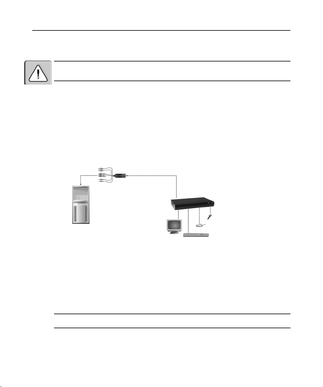
6 LongView IP KVM エクステンダー インス トーラ/ユーザー・ ガイド
インストール ・ オプション
注意 : 感電または機器への損傷の リ ス ク を抑え る ため、 受信機の電源を コ ン セ ン トか ら抜いて接続を外 し て く
だ さ い。 ま た、 次の手順 に説明 さ れている順序で リ モー ト ・ ワー ク ステーシ ョ ン お よ び受信機 を オ ンに し て く
ださい。
LongView IP KVM エクステンダーは、 ポイン ト ツーポイン ト方式を使用するか、 または
ネッ ト ワークを介してインストールするこ とができます。
ポイン ト ツーポイン ト ・ インスト ール
次の手順 を 使用す る と 、 LongView IP KVM エクステンダーをポイント ツーポイント構成
にインストールするこ とができます。 ポイントツーポイント構成では、 送信機または受
信機の管理者設定は不要です。 ただ し 、 ポ イ ン ト ツーポ イ ン ト 構成を選択 し た場合、 サ
ブネ ッ ト 上に イ ン ス ト ールで き る送信機 と 受信機のペア は 1 つのみです。
送信機
受信機
リモート ・ワークス
テーシ ョ ン
図 2.1 : ポイン ト ツーポイント ・ インストール
送信機を接続す る には :
リ モート ・ ワ ーク ス テーシ ョ ン に送信機を 接続する 前に、 リ モ ート ・ ワ ーク ス テーシ ョ ン
の解像度およ びリ フ レ ッ シュ ・ レ ート が LongView IP KVM エクステンダー・ システムに
よ っ て サポート さ れている こ と を 確認し てく ださ い。 リ モート ・ ワ ーク ス テーショ ン の画
面解像度およ びリ フ レッ シュ ・ レ ート を 、 付録 A に記載さ れた受信機のビ デオ解像度に
従っ て設定し ま す。 サポート さ れて いな い設定の場合、 受信機に何も 表示さ れま せん。
注: サポー ト 対象の解像度および リ フレ ッ シ ュ ・ レー ト の最新情報については、 www.avocent.com を参照し て
ください。
1. リモート ・ ワークステーションをオフにします。
2. 送信機には 2 個の USB コネク ターがあります。 各コネクターをリ モート ・ ワークス
テーシ ョ ンの該当する USB ポー ト に接続し ます。
3. 送信機のビデオ ・ コ ネ ク ターを、 ワー ク ステーシ ョ ン の背面にあ る、 該当 ラベルの
付いたポー ト に接続 し ます。
Page 65

章 2 : インストール 7
注: VGA のみのワー ク ス テーシ ョ ンは、 VGA - DVI-I ア ダプ タ ー を使用し て送信機に接続す る こ とがで き ま す。
送信機のビデオ設定は、 シ リ アル • メニューを使用して VGA に構成する必要があり ま
デオ入力設定の構成」 (ページ 18) を参照し て く ださい。
す。 詳細について は、 「ビ
4. 送信機のオーデ ィ オお よ びマ イ ク ロ フ ォ ン ・ コ ネ ク タ ー を 、 ワー ク ス テーシ ョ ンの
背面に あ る 、 該当 ラ ベルの付いた ポー ト に接続 し ます。
注: CD 品質のオーデ ィ オの場合、 シ リ アル ・ メ ニ ュ ー を 使用 し て送信機お よ び受信機を構成する必要があ り
ます。 詳細については、 「オーデ ィ オ ・ パ フ ォ ーマ ン スの設定」 (ページ 27) を参照して く だ さい。
5. UTP ケーブルの一方の端を送信機の RJ-45 コネク ターに接続します。
6. ワーク ステーシ ョ ンをオンにし ます。
7. UTP ケーブルの も う 一方の端を受信機用に選択 し た場所に配線 し ます。 必要に応 じ
て、 UTP ケーブルを分岐点ま たはハブを経由 し て延長す る こ と がで き ます (通常の
イーサネ ッ ト のケーブル接続方法に従います)。
送信機は、 リ モー ト ・ ワ ー ク ス テーシ ョ ンの 2 つの USB ポー ト か ら 電力を得ます。 1 つ
の USB ポー ト だけでは、 送信機をオンにする には不十分です。 リ モー ト ・ ワー ク ステー
ションにUSB ポー ト が 1 個 し か な い場合は、 送信機用の外部電源装置を弊社に ご 注文い
ただ く 必要があ り ます。
受信機
マイクロフォン
スピーカー
外部電源装置
PS/2
リモート ・ワーク
ステーショ ン
図 2.2 : 受信機およ び送信機の イ ンス トール
シリアル
USB で接続さ れた
ロー カ ル周辺機器
送信機
Page 66
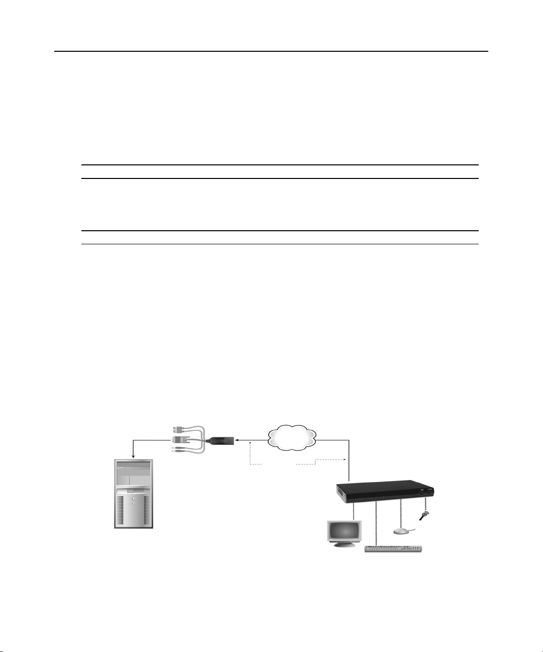
8 LongView IP KVM エクステンダー インス トーラ/ユーザー・ ガイド
電源の接続
受信機を接続す る には :
1. キーボー ド 、 モニ タ ー、 マ ウ ス などの周辺機器のケーブルを、 受信機の背面にあ る 、
該当 ラ ベルの付い た ポー ト に接続し ます。
2. 送信機か ら 延びてい る UTP ケーブル を 受信機の背面にあ る RJ-45 ポー ト に接続 し
ます。
注: 弊社が提供する 電源装置のみを 使用 し て く だ さい。
3. 受信機の電源装置に あ る 2.5 mm コ ネ ク タ ーの一方の端 を 受信機にあ る DC 電源
ジ ャ ッ ク に接続し ます。 も う 一方の端を適切な電源に接続 し ます。
4. 受信機をオ ン に し ます。 リ モー ト ・ ワー ク ス テーシ ョ ン と の接続が確立 さ れ ま す。
注: VGA モニターは、 DVI-I - VGA アダプターを使用して受信機に接続するこ とができます。
ネッ トワーク ・ インストール
次の手順 を 使用す る と 、 LongView IP KVM エク ステンダーをネッ ト ワーク構成にインス
トールすることができます。 このインストールでは、 同じイーサネット ・ネッ ト ワーク
を介し て複数の送信機お よ び受信機を接続す る こ と がで き ます。 こ の場合、 各ユニ ッ ト
が固有の IP アドレスで構成されていることが重要です。
送信機お よ び受信機は、 単一のサブ ネ ッ ト で使用する よ う に構成す る こ と も、 複数の
ルータ ーを経由し て使用す る よ う に構成する こ と もで き ま す。 ただ し 、 ルータ ー を 使用
する と 終端間の遅延が多少増加 し 、 ア プ リ ケーシ ョ ンに よ っては こ れ を 許容で き ない可
能性が あ り ます。
送信機
IP
ネッ トワーク
受信機
UTP
ケーブル
リモート ・ ワークステーシ ョン
図 2.3 : ネットワーク ・ インストール
Page 67

章 2 : インストール 9
LongView IP KVM エ ク ステ ンダーは、 工場のデ フ ォル ト ・ ネ ッ ト ワー ク 設定であ らか じ
め構成されてい ま す。 同じ サブネ ッ ト 上に複数のエ ク ス テ ン ダーを イ ン ス ト ールする場
合、 シ リ アル ・ ポー ト を介 し て各エ ク ステ ンダーに固有の IP アドレスを割り当てる必要
があ り ます。
表 2.1 : デフォルトのネッ トワーク設定
コンポーネント IP アドレス 種類
受信機
送信機
192.168.13.1
192.168.13.2
静的
静的
デフォルト ・
ゲー ト ウ ェ イ
0.0.0.0 255.255.255.0
0.0.0.0 255.255.255.0
サブネ ッ ト ・ マスク
ネッ トワーク上にLongView IP KVM エクステンダーをインストールするには:
1. 送信機を リ モー ト ・ ワー ク ス テーシ ョ ンに接続 し ます (前述の 「ポ イ ン ト ツーポイ
ント ・ インストール」 (ページ 6) を参照)。 UTP ケーブルの一方の端を送信機の RJ-
45 コ ネ ク ターに、 も う 一方の端を イ ーサネ ッ ト ・ ネッ ト ワーク に接続し ます。
2. 受信機を周辺機器に接続 し ます (前述の 「ポイント ツーポイント ・ インストール」
(ページ 6) を参照)。 長い UTP ケーブルを使用 し て、 受信機の背面にあ る RJ-45 コ
ネクターを介し受信機をイーサネッ ト ・ ネッ トワークに接続します。
3. 受信機を オ ン に し ます。
4. シ リ アル ・ メ ニュ ー を 使用 し て ま ず送信機の、 次に受信機のネ ッ ト ワ ー ク 設定 を 再
構成 し ます。 詳細につい ては
「ネ ッ ト ワー ク 設定の構成」 (ページ 13) を参照して く
ださい。
注: 受信機 と 送信機 を 異な るサブネ ッ ト 上に配置す る 場合は、 受信機 と 送信機のネ ッ ト ワー ク 設定を構成 し て
からネ ッ ト ワ ー ク に接続し ま す。 サブネ ッ ト 上で既に動作 し て い る送信機と受信機のペアがあ る 場合は、 新 し
い送信機 と 受信機のペア のネ ッ ト ワー ク 設定 を 構成 し てか ら ネ ッ ト ワー ク に 接続 し ます。
5. ネ ッ ト ワー ク 上に イ ン ス ト ールする送信機 と 受信機の各ペアに対 し て こ の手順を繰
り返します。
Page 68

10 LongView IP KVM エクステンダー インス トーラ/ユーザー・ ガイド
Page 69

章
3
概要
LongView IP KVM エクステンダーを介したリモート ・ ワークステーショ ンの操作は、
ワー ク ステーシ ョ ン に直接接続 し て の作業 と 変わ り ません。 受信機をオン にする と 、
自動的に ワー ク ステーシ ョ ン と の接続が確立し ます。
LongView IP KVM エ ク ステ ンダーのデフ ォル ト の設定はほ と んどのシ ス テ ム で機能 し ま
すが、 シ ス テ ムに合わせて設定を変更する こ と がで き ます。 シ リ アル ・ メ ニ ュ ーか ら 、
内部設定を変更 し た り 、 LongView KVM IP エクステンダーをアップグレードしたりする
ことができます。
LED の識別
11
操作
フロント ・ パネル
受信機の フ ロ ン ト ・ パネルには、 青色の LED が 2 個あ り ます。 PWR LED は、 受信機が
オン に な る と 点灯 し ます。 ACTIVE LED は、 受信機が送信機 と 接続 を 確立す る までは、
ゆっ く り と 点滅 し ます。 受信機 と 送信機の間で接続が確立す る と 、 ACTIVE LED は点滅
から点灯に変わり ます。
リア ・ パネル
受信機 と 送信機の背面には、 RJ-45 コネクターに LED が 2 個付いて い ま す。 次の表は、
それぞれの動作を示し た も のです。
表 3.1 : RJ-45 コネク ターのLED
LED
LED 1
LED 2
表示 意味
緑色の点灯 1 Gbps でのリ ン ク
緑色の点滅 100 Mbps でのリ ン ク
緑色の消灯 リンクなし
黄色の点灯 リンク中でアクティビティなし
黄色の点滅 ア ク テ ィ ビ テ ィの送受信中
Page 70

12 LongView IP KVM エクステンダー インス トーラ/ユーザー・ ガイド
システムへのアクセス
受信機がオン に な る と 、 受信機は リ モー ト ・ ワー ク ステーシ ョ ン と の接続 を開始 し ます。
注: リ モー ト ・ ワー ク ス テーシ ョ ンがオ フ に な っ て いる場合、 受信機は接続 を確立で き ま せん。
シリアル・ メニュー
受信機のシ リ アル ・ メ ニューか らは、 以下の操作 を 実行で き ます :
• 受信機 と 送信機の ネ ッ ト ワー ク 設定の構成
• パ ス ワー ド の設定ま たは変更
• 受信機 と 送信機の フ ァーム ウ ェアのア ッ プ グ レー ド
• 工場デフ ォ ル ト 設定への リ セ ッ ト
• セッシ ョンのタイムアウト値の設定
• オーデ ィ オ ・ パフ ォーマン ス 設定の変更
シリアル・ メニューへのアクセス
シ リ ア ル ・ メ ニ ュ ーには、 受信機背面に あ る シ リ アル ・ ポー ト か ら ア クセ ス で き ます。
すべてのターミ ナル・ コマンドは、 ターミナル・ エミ ュレーショ ン・ ソフト ウェアを実
行し て いる タ ーミ ナルま たは PC を介して実行されます。デフォルトでは、受信機から
LongView IP KVM エクステンダーにアクセスするには、 2 つのパ ス ワー ド が必要です。
1 つは受信機のパス ワー ド で、 も う 1 つは送信機のパス ワ ー ド です。 両方 と も 、 デ フ ォ
ルトのパスワードはpassword です。 デフ ォル ト のパ ス ワー ド の変更方法については、
「認証」 (ページ 20) を参照して く だ さい。
シリアル・ メニューにアクセスするために必要なアイテム
• シリアル・ポートを備えたネットワーク接続されているワークステーション
• ヌル ・ モデム ・ シ リ アル ・ ケーブル (オス DB-9)または3 線シ リ アル ・ ケーブル
• ターミ ナル ・ エミ ュレーシ ョ ン ・ ソ フ ト ウェア
シリアル・ メニューにアクセスするには:
1. シ リ アル ・ ケーブルの一端 を受信機背面にあ る シ リ アル ・ ポー ト に接続 し ます。
2. シ リ アル ・ ケーブルの他端 を PC のシ リ アル ・ ポー ト に接続し ます。
3. ターミ ナル ・ エミ ュレーシ ョ ン ・ ソ フ ト ウェアを起動します。 Com1 プロパティ ・ メ
ニ ューが表示 さ れ ます。
4. ターミ ナルのセッシ ョ ンを、 57600 bps、 8 デー タ ・ ビ ッ ト 、 パ リ テ ィ な し 、 1 ストッ
プ・ビット、フロー・コントロールなしに構成します。OK
注: ソフトウェア(XON/XOFF) フ ロ ー ・ コ ン ト ロ ールはサポー ト されていま すが、 XMODEM を使用する場合
は、 使用 し な い で く だ さ い。
をク リ ックします。
Page 71

章 3 : 操作 13
図 3.1 : Com1 プロパティ ・ メ ニュー
5. Enter キーを押すと、 シ リ アル ・ メ ニ ューが表示されます。 アプラ イアンス選択メ
ニ ューが表示 さ れ ます。
6. 1 を入力する と 受信機 メ ニ ュ ーに入 り 、 2 を 入力す る と 送信機 メ ニ ュ ーに入 り ます。
パス ワー ド の入力を 求め ら れ ます。
7. パ ス ワー ド を入力 し て、 Enter キーを押 し ます。
注: 受信機に接続 さ れてい る送信機がない場合、 エ ラ ー ・ メ ッ セー ジが表示 さ れ、 ア プ ラ イ ア ン ス選択 メ
ニューに戻ります。
シ リ アル ・ メ ニ ュ ーの操作
シ リ ア ル ・ メ ニ ュ ーの操作では、 選択する オプシ ョ ン に対応す る 番号 ま た は文字を 入力
してから、 Enter キーを押 し ます。 メ ニュ ーや画面を終了 し て変更 し た構成内容を確認
するには、 0 (ゼ ロ) を入力 し て Enter キーを押し ます。
ネ ッ ト ワーク 設定の構成
注: 受信機のネ ッ ト ワーク 設定 を構成する前に、 送信機のネ ッ ト ワー ク 設定 を構成する こ と を お勧め し ま す。
サポー ト されて いる IP ア ド レ スの指定方法は、 静的ア ド レス指定だけ です。
Page 72

14 LongView IP KVM エクステンダー インス トーラ/ユーザー・ ガイド
送信機のネ ッ ト ワー ク 設定を構成す る には :
1. シリアル・ メニューを起動します (「シ リ アル ・ メ ニ ューへのアク セス」 (ページ 12)
を参照)。
2. オプシ ョ ン 2 を選択して送信機 メ ニューにアクセス し、 Enter キーを押 し ます。 パ
ス ワ ー ド ・ オプシ ョ ンを有効に し て い る 場合は、 パ ス ワ ー ド を求め ら れ ま す。
3. パス ワ ー ド を入力 し て、 Enter キーを押 し ます。 送信機 メ イ ン ・ メ ニ ューが表示 さ れ
ます。
図 3.2 : 送信機メ イ ン ・ メ ニュ ー
注: 送信機メ イン ・ メ ニ ュ ーのア プ ラ イ ア ン スの リ セ ッ ト ・ オプ シ ョ ンは、 ネ ッ ト ワー ク 設定だけに適用 さ れ
ます。
4. 1 を押してネ ッ ト ワークの構成オプシ ョ ンを選択し、 Enter キーを押し ます。 ネ ッ ト
ワー ク 構成 メ ニ ュ ーが表示 さ れ ま す。
5. 1 を押して送信機のネッ ト ワーク構成オプシ ョ ンを選択し、 Enter キーを押し ます。
送信機ネ ッ ト ワー ク 構成 メ ニュ ーが表示 さ れ ます。
図 3.3 : 送信機ネ ッ ト ワーク 構成 メ ニ ュ ー
6. 1 を押して送信機の IP アドレス ・オプションを選択し、Enter キーを押 し ます。 有
効な IP アドレスを入力します。 Enter キーを押 し て、 送信機ネ ッ ト ワー ク 構成 メ
ニューに戻ります。
Page 73

章 3 : 操作 15
7. 同様に し て、 ネ ッ ト ワー ク と デ フ ォル ト ・ ネ ッ ト ワー ク を構成 し ます。
8. 0 (ゼ ロ ) を入力し てか ら Enter キーを押し て、 ネッ ト ワー ク 構成メ ニューに戻り ま
す。 入力に誤 り があ っ てネ ッ ト ワー ク 設定の変更を 保存 し た く な い場合は、 C を入
力して Enter キーを押し ます。
9. 変更内容を確認 し てそ の設定を適用す る には、 0 (ゼロ) を入力し て Enter キーを押
します。
10. 「Connection to the transmitter is lost (送信機 と の接続が切断 さ れ ま した)」 と い う シ ス
テ ム ・ メ ッ セージが表示 さ れ ま す。 次に、 自動的にアプ ラ イ ア ン ス 選択 メ ニ ュ ー画
面に戻 り ます。
11. オプシ ョ ン 1 を 選択 し て、 受信機 メ ニ ュ ーにア ク セ ス し ます。 パ ス ワー ド ・ オプ
シ ョ ン を有効に し てい る 場合は、 パ ス ワ ー ド を求め ら れ ま す。
12. パ ス ワー ド を入力 し て、 Enter キーを押 し ま す。 受信機 メ イ ン ・ メ ニ ューが表示 さ れ
ます。
図 3.4 : 受信機メ イ ン ・ メ ニュ ー
13. 1 を押してネ ッ ト ワーク の構成オプシ ョ ン を選択し、 Enter キーを押し ます。 ネッ
トワーク構成メニューが表示されます。
14. 1 を押して送信機の IP 構成オプシ ョ ン を選択 し 、 Enter キーを押 し ます。 送信機 IP
構成 メ ニューが表示 さ れ ます。 メ ニュ ー ・ オプ シ ョ ン 1 の横に、 送信機の古い IP ア
ド レ ス が表示 さ れ ます。
図 3.5 : 受信機の送信機構成メ ニュ ー
Page 74
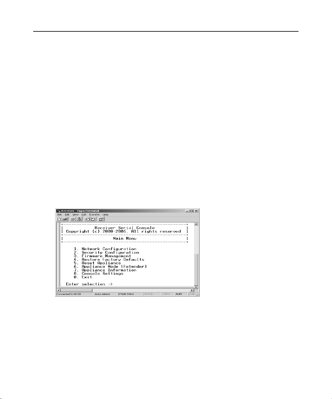
16 LongView IP KVM エクステンダー インス トーラ/ユーザー・ ガイド
15. 1 を押して送信機の IP アドレスを選択し、Enter キーを押 し ます。 送信機の新 し い
IP アドレスを入力します。 Enter キーを押し て、 送信機 IP 構成 メ ニューに戻 り ま
す。
16. 0 (ゼ ロ) を入力し てか ら Enter キーを押し て、 ネッ ト ワー ク 構成メ ニューに戻り
ます。
17. 入力に誤 り があ っ てネ ッ ト ワー ク 設定の変更 を保存 し た く ない場合は、 C を入力し
て Enter キーを押し ます。
18. 変更内容を確認 し てその設定 を 適用す る には、 0 (ゼ ロ ) を入力し て Enter キーを押
します。
19. 受信機は自動的に リ セ ッ ト さ れ、 新 し いネ ッ ト ワ ー ク 構成が適用 さ れま す。 次に、
自動的に ア プ ラ イ ア ン ス選択 メ ニ ュ ー画面に戻 り ます。 送信機への接続は、 自動的
に復元されます。
受信機のネ ッ ト ワー ク 設定を構成す る には :
1. シリアル・ メニューを起動します (「シ リ アル ・ メ ニ ューへのアク セス」 (ページ 12)
を参照)。
2. 1 を押して受信機 メ ニューにア ク セス し、 Enter キーを押し ます。 パス ワード ・ オプ
シ ョ ン を有効に し てい る 場合は、 パ ス ワ ー ド を求め ら れ ま す。
を参照し て く だ さ い。
3. パス ワ ー ド を入力 し て、 Enter キーを押 し ます。 受信機 メ イ ン ・ メ ニ ューが表示 さ れ
ます。
「認証」 (ページ 20)
図 3.6 : 受信機メ イ ン ・ メ ニュ ー
Page 75
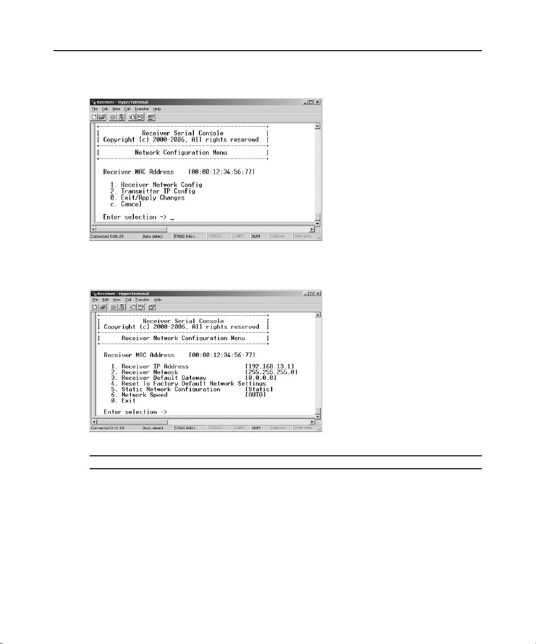
章 3 : 操作 17
4. 1 を押してネ ッ ト ワー クの構成を選択し、 Enter キーを押し ます。 ネッ ト ワーク構成
メニューが表示されます。
図 3.7 : ネッ トワーク構成メニュー
5. 1 を押して受信機のネッ ト ワーク構成を選択し、 Enter キー を押 し ま す。 受信機ネ ッ
ト ワー ク 構成 メ ニ ュ ーが表示 さ れ、 現在のネ ッ ト ワー ク 設定が表示 さ れま す。
図 3.8 : 受信機ネ ッ ト ワーク 構成 メ ニ ュ ー
注: 受信機ネットワーク構成メニューのリセット・オプションは、 ネットワーク設定だけに適用されます。
6. 1 を押し て受信機の IP アドレスを選択し、Enter キーを押し ます。
7. 有効な IP アドレスを入力します。 Enter キーを押 し て、 受信機ネ ッ ト ワー ク 構成 メ
ニューに戻ります。
8. 2 を押して受信機のネ ッ トマス ク を選択し、 Enter キーを押し ます。
9. 有効な受信機のネ ッ ト マス ク を 入力し ます。 Enter キーを押 し て、 受信機ネ ッ ト
ワーク構成メ ニューに戻り ます。
10. 3 を押して受信機のデフォル ト ・ ゲー ト ウ ェ イ を選択し、 Enter キーを押し ます。
11. 有効な受信機のデ フ ォル ト ・ ゲー ト ウ ェ イ を入力 し ま す。 Enter キーを押し て、 受
信機ネ ッ ト ワー ク 構成 メ ニ ュ ーに戻 り ます。
Page 76

18 LongView IP KVM エクステンダー インス トーラ/ユーザー・ ガイド
12. 0 (ゼ ロ) を入力し てか ら Enter キーを押し て、 ネッ ト ワーク 構成メ ニューに戻り
ます。
13. 入力に誤 り があ っ てネ ッ ト ワー ク 設定の変更 を保存 し た く ない場合は、 C を入力し
て Enter キーを押し ます。
14. 変更内容 を 確認 し て そ の設定を適用する には、 0 (ゼロ) を入力し て Enter キーを押
します。
注: ネ ッ ト ワーク構成の変更内容は、 ネ ッ ト ワーク構成 メ ニ ュ ー を 終了 し た後に適用 さ れます。
15. 受信機は自動的に リ セ ッ ト さ れ、 新 し いネ ッ ト ワ ー ク 構成が適用 さ れま す。 リ セ ッ
ト 中は、 受信機は送信機と の接続を解除 し ます。 次に、 自動的に ア プ ラ イア ン ス 選
択 メ ニ ュ ーに戻 り ます。 接続は自動的に復元 さ れ ます。
ビデオ入力設定の構成
LongView IP KVM エク ステンダー・ システムは、 リモート ・ ワークステーシ ョ ンからモ
ニターへ、 デジタル・ ビデオ (DVI) またはアナログ ・ ビデオ (VGA) を送信する こ とがで
き ます。 シ ス テ ム が適切な ビデオ信号をモニ タ ーに送信で き る よ う にする には、 ま ず送
信機の ビ デオ入力設定 を 構成す る 必要があ り ます。
注: ビ デオ入力設定が正 し く 構成 さ れていな い と 、 ビ デオやデ ィ ス プ レ イ で問題が発生す る可能性があ り ます。
ビデオ入力設定を構成するには :
1. シリアル・ メニューを起動します (「シ リ アル ・ メ ニ ューへのアク セス」 (ページ 12)
を参照)。
2. オプシ ョ ン 2 を選択 し て送信機 メ ニ ュ ーにア ク セス し、 Enter キーを押 し ます。 パ
ス ワ ー ド ・ オプシ ョ ンを有効に し て い る 場合は、 パ ス ワ ー ド を求め ら れ ま す。
証」 (ページ 20) を参照して く ださい。
3. パ ス ワー ド を入力 し て、 Enter キーを押 し ま す。 送信機 メ イ ン ・ メ ニ ュ ーが表示 さ
れます。
4. 7 を押し て コ ンソールの設定を選択し、 Enter キーを押し ます。 コ ン ソール設定メ
ニ ューが表示 さ れ ます。 タ ーゲ ッ ト ・ ビ デオ ・ オプ シ ョ ンの横に、 現在のビデオ入力
設定が表示 さ れ ま す。
「認
図 3.9 : 送信機コ ン ソ ール設定 メ ニュ ー
Page 77

章 3 : 操作 19
5. 1 を押してターゲッ ト ・ ビデオを選択し、 Enter キーを押し ます。 ターゲ ッ ト ・ ビデ
オ・ メニューが表示されます。
図 3.10 : 送信機タ ーゲ ッ ト ・ ビデオ ・ メ ニュ ー
6. DVI と VGA を切 り 替えるには、 1 を押し てターゲッ ト ・ ビデオ - DVI/VGA オプシ ョ
ンを選択し、 Enter キーを押し ます。
7. メニュー・オプショ ン 1 の横に、 更新 さ れた設定が表示 さ れ ま す。
8. 変更内容を保存 し て メ ニュ ー を 終了す る には、 0 (ゼ ロ) を入力し て Enter キーを押
します。 ユニットは、 Enter キーを押し た後に リ セッ ト されます。
送信機の IP ア ド レ スの検出
送信機の IP ア ド レ ス を忘れた場合、 シ リ アル ・ メニューを使って受信機に接続されてい
る送信機の IP アドレスを検出することができます。
接続さ れている送信機の IP アドレスを検出するには:
1. 送信機が接続 さ れてい る リ モー ト ・ ワ ー ク ス テーシ ョ ン を オ フ に し ま す。
注: 送信機が外部電源を使用 し て い る場合は、 送信機を外部電源から取 り 外 し て く だ さ い。
2. 1 を押して受信機 メ ニューを選択し、 Enter キーを押し ます。 パス ワー ド ・ オプシ ョ
ンを有効にしている場合は、 パスワードを求められます。
照して く ださい。
3. パ ス ワー ド を入力 し て、 Enter キーを押 し ま す。 受信機 メ イ ン ・ メ ニ ュ ーが表示 さ
れます。
4. 1 を押してネ ッ ト ワークの構成を選択し、 Enter キーを押し ます。 ネッ ト ワーク構成
メニューが表示されます。
5. 2 を押して送信機の IP 構成を選択し 、 Enter キーを押 し ます。 送信機 IP 構成 メ
ニューが表示されます。 メ ニュー・ オプショ ン 1 の横に、 送信機の古い IP アドレス
が表示されます。
6. 3 を押して送信機ア ド レ スの検出を選択し、 Enter キーを押し ます。 「Connect the
transmitter and the receiver, then power up the transmitter (送信機 と 受信機を接続 し て、
送信機の電源 を入れて く だ さ い)」 と い う メ ッ セージが表示 さ れ ま す。
「認証」 (ページ 20) を参
Page 78

20 LongView IP KVM エクステンダー インス トーラ/ユーザー・ ガイド
7. 送信機を オ ン に し ます。
8. 受信機が、 接続 さ れてい る 送信機の IP ア ド レ ス を 検出 し ます。 送信機 IP 構成 メ
ニューが更新され、 メニュー・ オプショ ン 1 の横に、 接続 さ れてい る 送信機の現在
の IP アドレスが表示されます。
注: 接続されている送信機の検出 さ れた IP アドレスは、 自動的には保存されません。検出されたIP アドレス
は、 送信機 IP 構成 メ ニュ ーから
送信機
の IP
アドレス
を選択し て、 手動で入力する必要が あ り ます。
認証
シリアル・ メニューを介してLongView IP KVM エクステンダーにアクセスするには、 2
つのパス ワ ー ド が必要です。 1 つは受信機を制御する シ リ アル ・ メ ニューにア ク セスす
るためのパスワードです。 も う 1 つは、 送信機を制御する シ リ アル ・ メ ニ ュ ーにア ク セ
スす る た めのパス ワ ー ド です。 両方 と も 、 デ フ ォル ト のパ ス ワー ド は password です。
受信機の認証
受信機のパス ワー ド 設定は、 シ リ アル ・ メ ニ ュ ーの受信機セ キ ュ リ テ ィ 構成 メ ニ ュ ー
を
使って変更でき ます。
受信機セ キ ュ リ テ ィ 構成 メ ニュ ーにア ク セ スす る には :
1. シリアル・ メニューを起動します (「シ リ アル ・ メ ニ ューへのアク セス」 (ページ 12)
を参照)。
2. オプシ ョ ン 1 を選択 し て、 受信機 メ ニ ュ ーに ア クセ ス し ます。 パ ス ワー ド ・ オプ
シ ョ ン を有効に し てい る 場合は、 パ ス ワ ー ド を求め ら れ ま す。
「認証」 (ページ 20)
を参照し て く だ さ い。
3. パ ス ワー ド を入力 し て、 Enter キーを押 し ま す。 受信機 メ イ ン ・ メ ニ ュ ーが表示 さ
れます。
4. セキ ュ リ テ ィ の構成を 選択 し ます。 セキ ュ リ テ ィ 構成 メ ニ ュ ーが表示さ れ ま す。
図 3.11 : 受信機セキ ュ リ テ ィ 構成 メ ニュ ー
Page 79

章 3 : 操作 21
受信機のパスワー ド を無効または有効にする には :
1. 1 を押してセキュ リ テ ィ 構成メ ニ ューのコ ン ソール ・ パス ワード を選択し、 Enter
キー を 押 し ます。 パ ス ワー ド が有効にな っ て い た場合、 こ の操作に よ ってパ ス ワ ー
ド が無効にな り ま す。
2. パ ス ワー ド が無効にな っ て い た場合、 パ ス ワ ー ド を入力す る よ う に求め ら れま す。
3. 新しいパスワード を入力して、 Enter キーを押し ます。
注: パスワードは、 6 ~ 64 文字の ASCII 文字であ る必要があ り ま す。
4. 確認のため、 新しいパスワード をも う一度入力します。 正し く入力すると、 パス
ワー ド が変更 さ れ ま し た と い う メ ッ セージ が表示 さ れ ます。
5. Enter キーを押し ます。
6. 変更内容を保存 し て メ ニュ ー を 終了す る には、 0 (ゼ ロ) を入力し て Enter キーを押
します。
受信機のパスワー ド を変更す るには :
1. 2 を押してセキュ リ テ ィ構成メ ニ ューのコ ン ソール ・ パス ワードの変更を選択し、
Enter キ ーを 押 し ます。 現在のパス ワ ー ド を入力す る よ う に求め ら れ ます。
2. 現在のパス ワー ド を入力し て、 Enter キーを押し ます。 新しいパス ワード を入力す
るように求められます。
3. 新しいパスワード を入力して、 Enter キーを押し ます。
注: パスワードは、 6 ~ 64 文字の ASCII 文字であ る必要があ り ま す。
4. 確認のため、 新しいパスワード をも う一度入力します。 正し く入力すると、 パス
ワー ド が変更 さ れ ま し た と い う メ ッ セージ が表示 さ れ ます。
5. Enter キーを押し ます。
6. 変更内容を保存 し て メ ニュ ー を 終了す る には、 0 (ゼ ロ) を入力し て Enter キーを押
します。
受信機ま たは送信機のパス ワー ド を リ セ ッ ト す るには :
受信機ま たは送信機のパ ス ワー ド が分か ら な く な っ た場合、 弊社テ ク ニカル ・ サポー ト
に連絡し て、 シ ステ ム をデ フ ォ ル ト のパス ワー ド に リ セッ ト す る こ と がで き ます。
1. シリアル・ メニューにアクセスします (12 ページ の 「シ リ ア ル ・ メ ニ ュ ーへの ア ク
セス」 を参照)。
2. オプシ ョ ン 1 を選択して受信機メ ニューにア ク セ スするか、 オプシ ョ ン 2 を選択し
て送信機メ ニ ューにア ク セス し て、 Enter キーを押 し ます。
3. 現在のパス ワー ド を入力する よ う に求め ら れ ま す。 ?????? (6 つの疑問符) を 入力 し
て、 Enter キーを押し ま す。 シ リ アル ・ メ ニ ュ ーで も キーを 入力する よ う に求め ら
れます。
4. 弊社テ ク ニ カル ・ サポー ト に連絡し て、 キーを取得 し ます。 テ ク ニカル ・ サポー ト
の担当者は、 16 文字の 16 進コード を質問し ます。 シリ アル ・ メニューに表示されて
い る コー ド を正確に伝え ます。 担当者か ら 新 し い 16 文字の 16 進コード を教えられ
ます。
Page 80

22 LongView IP KVM エクステンダー インス トーラ/ユーザー・ ガイド
5. シ リ アル・ メニューで、 キーと して弊社テクニカル ・ サポート から取得した16 文字
の 16 進コードを入力します。 Enter キーを押し ます。
6. これで、 デフォルト のパスワードが有効になり ます。
送信機の認証
送信機のパス ワー ド 設定は、 シ リ アル ・ メ ニ ュ ーか ら 送信機セ キ ュ リ テ ィ 構成 メ ニ ュ ー
を使っ て変更で き ます。
送信機セ キ ュ リ テ ィ 構成 メ ニュ ーにア ク セ スす る には :
1. シリアル・ メニューを起動します (「シ リ アル ・ メ ニ ューへのアク セス」 (ページ 12)
を参照)。
2. オプシ ョ ン 2 を選択 し て送信機 メ ニ ュ ーにア ク セス し、 Enter キーを押 し ます。 パ
ス ワ ー ド ・ オプシ ョ ンを有効に し て い る 場合は、 パ ス ワ ー ド を求め ら れ ま す。
証」 (ページ 20) を参照して く ださい。
3. パ ス ワー ド を入力 し て、 Enter キーを押 し ま す。 送信機 メ イ ン ・ メ ニ ュ ーが表示 さ
れます。
4. 2 を押してセキ ュ リ ティ の構成を選択し、 Enter キーを押し ます。 セキュ リ テ ィ 構成
メニューが表示されます。
「認
図 3.12 : 送信機セキ ュ リ テ ィ構成 メ ニ ュ ー
送信機のパスワー ド を無効または有効にする には :
1. 1 を押してセキュ リ テ ィ 構成メ ニ ューのコ ン ソール ・ パス ワード を選択し、 Enter
キー を 押 し ます。 パ ス ワー ド が有効にな っ て い た場合、 こ の操作に よ ってパ ス ワ ー
ド が無効にな り ま す。
2. パ ス ワー ド が無効にな っ て い た場合、 パ ス ワ ー ド を入力す る よ う に求め ら れま す。
3. 新しいパスワード を入力して、 Enter キーを押し ます。
注: パスワードは、 6 ~ 64 文字の ASCII 文字であ る必要があ り ま す。
4. 確認のため、 新しいパスワード をも う一度入力します。 正し く入力すると、 パス
ワー ド が変更 さ れ ま し た と い う メ ッ セージ が表示 さ れ ます。
5. Enter キーを押し ます。
Page 81

章 3 : 操作 23
6. 変更内容を保存 し て メ ニュ ー を 終了す る には、 0 (ゼ ロ) を入力し て Enter キーを押
します。
送信機のパスワー ド を変更す るには :
1. 2 を押してセキュ リ テ ィ構成メ ニ ューのコ ン ソール ・ パス ワードの変更を選択し、
Enter キ ーを 押 し ます。 現在のパス ワ ー ド を入力す る よ う に求め ら れ ます。
2. 現在のパス ワー ド を入力し て、 Enter キーを押し ます。 新しいパス ワード を入力す
るように求められます。
3. 新しいパスワード を入力して、 Enter キーを押し ます。
注: パスワードは、 6 ~ 64 文字の ASCII 文字であ る必要があ り ま す。
4. 確認のため、 新しいパスワード をも う一度入力します。 正し く入力すると、 パス
ワー ド が変更 さ れ ま し た と い う メ ッ セージ が表示 さ れ ます。
5. Enter キーを押し ます。
6. 新しいパスワード を確認して画面を終了するには、 0 (ゼ ロ ) を 入力 し て Enter キー
を押し ます。
LongView IP KVM エクステンダーのFlash アップグレード
注: 受信機の Flash アップグレードを行う前に、 送信機のFlash アップグレードを行うことをお勧めします。
受信機 と 送信機は、 XMODEM またはHTTP を使用して Flash アップグレードすることが
で き ます。 受信機 と 送信機は、 弊社が提供する それぞれのア ッ プグ レー ド ・ フ ァ イル を
使っ て、 別々にア ッ プグ レー ド さ れま す。 シ ス テ ムの最適な性能を確保で き る よ う に、
ファームウェアは常に最新バージョンのものを使用してください。
注: XMODEM を使用する場合は、 ソ フ ト ウ ェ ア (XON/XOFF) フロー・ コン トロールを使用しないでください。
XMODEM を 使用 し て送信機または受信機を Flash アップグレードするには:
1. 弊社か ら 送信機の ア ップ グ レ ー ド ・ フ ァ イル を ダ ウ ン ロー ド し ま す。
2. シリアル・ メニューを起動します (「シ リ アル ・ メ ニ ューへのアク セス」 (ページ 12)
を参照)。
3. オプシ ョ ン 1 を選択して受信機メ ニューにア ク セ スするか、 オプシ ョ ン 2 を選択し
て送信機メ ニ ューにア ク セス し ます。 パス ワー ド ・ オプシ ョ ンを有効にし てい る場
合は、 パ ス ワー ド を求め ら れ ます。
4. パ ス ワー ド を入力 し て、 Enter キーを押 し ま す。 送信機 メ イ ン ・ メ ニ ュ ーが表示 さ
れます。
5. 3 を押してフ ァーム ウ ェアの管理を選択し、 Enter キーを押 し ます。 フ ァーム ウ ェ ア
管理 メ ニューが表示 さ れ ます。
6. XMODEM から Flash ア ッ プグ レ ー ド ・ オプ シ ョ ンを選択 し て、 Enter キーを押し
ます。
7. アップグレー ド ・ フ ァ イルの場所を指定して、 ファ イル転送を開始し ます。
Page 82

24 LongView IP KVM エクステンダー インス トーラ/ユーザー・ ガイド
8. 転送が完了する と 、 「Firmware update successful. Resetting Appliance... (フ ァームウ ェ
アの更新が成功し ま した。 アプラ イ アンスを リ セ ッ ト しています ...)」 と い う メ ッ
セージが表示 さ れま す。 リ セ ッ ト 中は、 送信機は受信機 と の接続を解除 し ます。 2 番
目のシ ス テム ・ メ ッ セージ と し て、 「Connection to the transmitter is lost (送信機 と の接
続が失われました)」 とい う メ ッ セージが表示されます。 次に、 自動的にアプラ イ ア
ンス選択メニューに戻り ます。
注: ア ッ プ グ レ ー ド ・ フ ァ イルが無効である と送信機ま たは受信機が判断 し た場合、 送信機はア ッ プグレー ド
を中止 し て、 今ま でのフ ァ ームウ ェ ア ・ バージ ョ ンのま まに し ます。 次に、 ア ップグ レー ド が失敗し た こ と を
示す メ ッ セ ージが表示 さ れます。
工場のデ フ ォ ル ト 設定の復元
シ リ ア ル ・ メ ニ ュ ーを使用す る と 、 受信機 と 送信機の工場出荷時のデ フ ォル ト 設定を 簡
単に復元する こ と がで き ます。 工場のデフ ォ ル ト 設定の全 リ ス ト については、
フ ォ ル ト 設定」 (ページ 33) を参照して く ださい。
注: 工場のデフ ォル ト 設定を復元する と、 ネ ッ ト ワーク設定も リ セ ッ ト されます。 工場のデ フ ォル ト 設定を 復
元する前に、 ネ ッ ト ワー ク上にあ る 他のデバ イ ス と 競合が発生 し ないか評価 し て く だ さ い。
送信機ま たは受信機の工場のデ フ ォ ル ト 設定を 復元する には :
1. シリアル・ メニューを起動します (「シ リ アル ・ メ ニ ューへのアク セス」 (ページ 12)
を参照)。
2. オプシ ョ ン 1 を選択して受信機メ ニューにア ク セ スするか、 オプシ ョ ン 2 を選択し
て送信機メ ニ ューにア ク セス し ます。 パス ワー ド ・ オプシ ョ ンを有効にし てい る場
合は、 パ ス ワー ド を求め ら れ ます。
3. パ ス ワー ド を入力 し て、 Enter キーを押 し ます。
4. 4 を押 し て工場のデフ ォル ト の復元を選択し、 Enter キーを押し ます。
5. こ れで、 受信機が自動的に リ セ ッ ト さ れ ま す。 次に、 自動的にアプ ラ イア ン ス 選択
メニューに戻ります。
6. リ セ ッ ト 中は、 受信機は送信機 と の接続を解除 し ます。 リ セッ ト が完了する と 、 受
信機は新 し い設定を使用 し て送信機 と の接続を復元 し ます。
「工場デ
LongView IP KVM エクステンダーのリセッ ト
受信機ま たは送信機 を リ セ ッ ト するには :
1. シリアル・ メニューを起動します (「シ リ アル ・ メ ニ ューへのアク セス」 (ページ 12)
を参照)。
2. オプシ ョ ン 1 を選択して受信機メ ニューにア ク セ スするか、 オプシ ョ ン 2 を選択し
て送信機メ ニ ューにア ク セス し ます。 パス ワー ド ・ オプシ ョ ンを有効にし てい る場
合は、 パ ス ワー ド を求め ら れ ます。
3. 受信機 メ イ ン ・ メ ニ ュ ーが表示 さ れ ます。
4. 5 を押してアプラ イアンスの リ セ ッ ト を選択し、 Enter キーを押 し ます。 ア プ ラ イ ア
ンス ・ リセッ ト ・ メニューが表示されます。
Page 83

章 3 : 操作 25
図 3.13 : 受信機アプ ラ イア ン ス ・ リ セ ッ ト ・ メ ニュ ー
5. 1 を押して受信機の リ セ ッ ト を選択し、 Enter キーを押し て リ セッ ト を開始します。
「Restting appliance (アプラ イ アン ス を リ セ ッ ト してい ます)」 と い う メ ッ セージがシ
リ アル ・ メ ニ ュ ー上に表示 さ れ ます。 リ セッ ト 中は、 送信機への接続は解除 さ れ ま
す。 リ セ ッ ト が完了す る と 、 自動的にアプ ラ イア ン ス 選択 メ ニ ュ ーに戻 り ま す。 送
信機への接続は、 自動的に復元 さ れ ま す。
送信機を リ セ ッ ト する には :
1. シリアル・ メニューを起動します (「シ リ アル ・ メ ニ ューへのアク セス」 (ページ 12)
を参照)。
2. オプシ ョ ン 2 を選択 し て送信機 メ ニ ュ ーにア ク セス し ま す。 パ ス ワー ド ・ オプ シ ョ
ンを有効にしている場合は、 パスワードを求められます。
照して く ださい。
3. 送信機 メ イ ン ・ メ ニ ュ ーが表示 さ れ ます。
4. 5 を押してアプラ イアンスの リ セ ッ ト を選択し、 Enter キーを押 し ます。 ア プ ラ イ ア
ンス ・ リセッ ト ・ メニューが表示されます。
5. 1 を押して送信機の リ セ ッ ト を選択し、 Enter
「Restting appliance (アプラ イ アン ス を リ セ ッ ト してい ます)」 と い う メ ッ セージがシ
リ アル ・ メ ニ ュ ー上に表示 さ れ ます。 リ セッ ト 中は、 送信機は受信機 と の接続を解
除します。 2 番目のシ ス テ ム ・ メ ッ セージ と し て、 「Connection to the transmitter is lost
(送信機 と の接続が失われ ま し た)」 と い う メ ッ セージ が表示 さ れ ます。 次に、 自動
的にア プ ラ イ ア ン ス選択メ ニューに戻 り ます。 接続は自動的に復元さ れ ます。
シス テム情報の表示
シ リ ア ル ・ メ ニ ュ ーを使用す る と 、 受信機 と 送信機の フ ァーム ウ ェ ア の リ リ ース や詳細
情報を表示する こ とがで き ま す。
システム情報を表示するには:
1. シリアル・ メニューを起動します (「シ リ アル ・ メ ニ ューへのアク セス」 (ページ 12)
を参照)。
キーを押して
「認証」 (ページ 20) を参
リセットを開始します。
Page 84

26 LongView IP KVM エクステンダー インス トーラ/ユーザー・ ガイド
2. オプシ ョ ン 1 を選択 し て受信機 メ ニ ュ ーにア ク セ ス す る か、 オ プ シ ョ ン 2 を選択 し て送信機 メ
ニ ュ ーにア ク セ ス し ます。 パ ス ワ ー ド ・ オプ シ ョ ンを有効に し て い る場合は、 パ ス ワー ド を求
められます。
3. パス ワ ー ド を入力し て、 Enter キー を 押 し ます。 受信機 メ イ ン ・ メ ニューが表示さ れ ま す。
4. 6 を押してアプラ イ アンスの情報を選択し、 Enter キーを押し ます。 アプ ラ イ アン ス情報メ
ニ ュ ーが表示 さ れ ま す。
アプ ラ イア ン ス 情報 メ ニ ュ ーには、 受信機名、 EID 番号、 リ リ ー ス ・ バージ ョ ン、 アプ
リケーション、ブートおよびFPGA フ ァ ー ム ウ ェ アのバージ ョ ン 番号、 製造部品番号な
どの情報が表示 さ れま す。 すべて の値は読み取 り専用です。
セ ッ シ ョ ン再試行の設定
LongView IP KVM エクステンダーは、 受信機と リモート ・ ワークステーション間の接続
を自動的に確立する よ う に設計 さ れてい ま す。 デ フ ォル ト では、 受信機が リ モー ト ・
ワー ク ステーシ ョ ン と す ぐ に接続を確立で き な い場合、 受信機は接続が正常に確立 さ れ
るまで、 1 秒間に 1 回再試行を実行 し ま す。 シ リ ア ル ・ メ ニ ュ ーを使用 し て、 こ のセ ッ
シ ョ ン再試行のデフ ォル ト の設定を変更す る こ とがで き ま す。
セッショ ン再試行メニューにアクセスするには:
1. シリアル・ メニューを起動します (「シ リ アル ・ メ ニ ューへのアク セス」 (ページ 12)
を参照)。
2. オプシ ョ ン 1 を選択して受信機メ ニューにアクセスし、 必要に応じてパスワード を
入力 し ます。 受信機 メ イ ン ・ メ ニ ュ ーが表示 さ れ ます。
3. 8 を押して コ ン ソールの設定を選択し、 Enter キーを押し ます。 コン ソール設定 メ
ニ ューが表示 さ れ ます。
4. セ ッ シ ョ ンの再試行に対応する 番号 を 入力 し て、 Enter キ ー を 押 し ます。 セ ッ シ ョ ン
再試行 メ ニューが表示 さ れ ます。
図 3.14 : セッショ ン再試行メニュー
再試行の設定を変更す る には :
1. シ リ アル ・ メ ニューか ら セ ッ シ ョ ン再試行メ ニ ューにア クセス し ます (前述の手順
を参照)。
Page 85

2. 再試行の間隔を変更する には、 1 を 押 し て セ ッ シ ョ ン再試行の タ イ ム ア ウ ト (秒)
オプシ ョ ン を選択し、 Enter キーを押 し ます。 する と 、 新 し い タ イム ア ウ ト 値を S
(秒) の形式で入力する よ う に求め ら れ ます。
3. 1 ~ 60 の値を入力し て、 Enter キーを押し ます。
4. 選択内容を確認 し て画面を終了す る には、 0 (ゼロ ) を入力し て Enter キーを押 し
ます。
オーデ ィ オ ・ パフ ォーマ ン スの設定
このオプシ ョ ンを使用すると、 オーディオ ・ パフォーマンスの設定を変更した り、 オー
デ ィ オのサポー ト を無効に し た り する こ と がで き ます。 設定には、 高、 中、 オ フ の 3 種
類があ り ます。 設定 を 高にす る と、 最高のオーデ ィ オ ・ パ フ ォ ーマ ン ス にな り ます。 こ
れは、 ネ ッ ト ワー ク 帯域幅が大き い場合に使用し ます。
注: オー デ ィ オが正し く 動作する よ う に、 受信機 と 送信機は同 じ オ ーデ ィ オ ・ パ フ ォ ー マ ン ス 設定に構成 し て
ください。
受信機 と 送信機のオーデ ィ オ ・ パフ ォーマン スの設定を変更する には :
1. シリアル・ メニューを起動します (「シ リ アル ・ メ ニ ューへのアク セス」 (ページ 12)
を参照)。
2. オプシ ョ ン 1 を選択して受信機メ ニューにア ク セ スするか、 オプシ ョ ン 2 を選択し
て送信機メ ニ ューにア ク セス し ます。 パス ワー ド ・ オプシ ョ ンを有効にし てい る場
合は、 パ ス ワー ド を求め ら れ ます。
3. パ ス ワー ド を入力 し て、 Enter キーを押 し ま す。 送信機 メ イ ン ・ メ ニ ュ ーが表示 さ
れます。
4. 7 を押して コ ン ソールの設定を選択し、 Enter キーを押し ます。 コン ソール設定 メ
ニ ューが表示 さ れ ます。
5. 2 を押してオーディ オ ・ パフ ォーマン ス を選択し、 Enter キーを押し ます。 オーデ ィ
オ ・ パフォーマンス ・ メ ニューが表示されます。 この メ ニューには、 選択できる
オーデ ィ オ設定が表示 さ れます。 現在の設定には、 ア ス タ リ ス ク (*) 記号が付いてい
ます。
6. 適用する オーデ ィ オ設定に対応する番号を入力し て、 Enter キーを押し ます。
注: オフを選択した場合、 オーディオ ・サポートは無効になります。
章 3 : 操作 27
7. 選択内容を確認 し て画面を終了す る には、 0 (ゼロ ) を入力し て Enter キーを押 し ま
す。 ユ ニ ッ ト は、 Enter キーを押した後にリセットされます。
Page 86

28 LongView IP KVM エクステンダー インス トーラ/ユーザー・ ガイド
Page 87

付録
ïtò^
付録 A : 技術仕様
本製品の有効期間の間に、 予告な し に こ こに記載の仕様の変更が必要と な る修正がハー
ドウェアまたはファームウェアに加えられることがあります。
表 A.1 : 受信機の製品仕様
ネットワーク
29
イーサネッ ト標準
IP ポー ト の使用状況 ポー ト 16384 - ビデオ
拡張ポー ト
個数
コネクター
ユーザー ・ ポート
個数
種類
コネクター
暗号化
種類
コンソール ・ ポート
個数
イーサネ ッ ト II
ポー ト 16385 - オーディ オ
ポー ト 16386 - キーボー ド/マウス
ポー ト 4463、 4464、 4465 - 制御
1
RJ-45
PS/2 : 2、 USB : 4、 DVI-I ビデオ : 1、オーディオ・マイクロフォン:
1、オーディオ・ライン出力:1、電源ジャック: 1
PS/2、 USB タイプA、 DVI-I ビデオ
6 ピン miniDIN、 PS/2 キーボー ド およびマウス ; USB タイプA、 USB
キーボー ド およびマウス ; DVI-I、メス; 3.5 mm ステレオ ・ オーディ
オ・ジャック、 ライン出力およびマイク; 2.5
認証 SSL
1
mm DC 電源ジ ャ ッ ク
種類
コネクター
三線シ リ アル ・ イ ン ター フ ェ イ ス : 16450 互換 UART を介した RX、
TX、 GND
9 ピン D シェル (DB9)
Page 88

30 LongView IP KVM エクステンダー インス トーラ/ユーザー・ ガイド
表 A.1 : 受信機の製品仕様 (続き)
寸法
H x W x D
重量
環境
熱放散
電気消費量
AC 入力電源
AC 定格入力電流
AC 周波数
作動温度
保管温度
輸送温度
作動湿度
保管湿度
サポー ト 対象ハー ド
ウェア
周辺機器
26.5 x 210 x 130 mm (1.04 x 8.27 x 5.12 in)
0.7 Kg (1.54 lb) (梱包材、 ケー ブ ル、 電源装置、 マ ニ ュ アルを 除 く )
22 W/H
20 W (USB ポー ト に供給さ れる電力を含む)
100-240 V AC
1 A
50/60 Hz
0 ~ 35 ℃(32 ~ 95 °F)
-20 ~ 60 ℃(-4 ~ 140 °F)
-30~60℃(-22~140 °F
10 ~ 90% 結露な し
5 ~ 95%
PS/2 キーボード とマウス、 USB キーボー ド と マウス、 スピーカ ー、
マイクロフォン
)
キーボー ド
マウス
PC、 Macintosh、およびSun 向け標準 104 / 105 / 109 キーボー ド
PC、 Macintosh、およびSun 向け USB キーボー ド
Microsoft Windows、 MacOS、 Solaris、およびRed Hat Linux のデフ ォ
ル ト ・ キーボー ド ・ ド ラ イバーは完全にサポート されています。
2 ボタン、 3 ボタン、 および5 ボタ ン ; スクロール・ ホイールおよびチ
ルト ・ ホイール
Page 89

表 A.1 : 受信機の製品仕様 (続き)
付録 31
ビデオ解像度
ビデオ標準
色
オーデ ィ オ標準
オーデ ィ オ性能
高パフ ォ ーマ ンス ライン出力:
中パフ ォ ーマ ンス ライン出力:
640 x 350 @ 85 Hz
640 x 480 @ 60 Hz、 72 HZ、 75 Hz、 85 Hz
720 x 400 @ 70 Hz、 85 Hz
800 x 600 @ 60 Hz、 72 Hz、 75 Hz、 85 Hz
1024 x 768 @ 60 Hz、 70 Hz、 75 Hz、 85 Hz
1152 x 864 @ 75 Hz
1280 x 960 @ 60 Hz
1280 x 1024 @ 60 Hz
サポー ト対象のビ デオ解像度および リ フレ ッ シ ュ ・ レー ト の最新 リ ス
トについては、www.avocent.com を確認し て く ださい。
DDC バージ ョ ン 2B
24 ビッ ト
PC99
16 ビ ッ ト 分解能、 ス テ レオ ・ チャ ン ネル、 44.1 kHz
マイクロフォン :
16 ビ ッ ト の解像度 で単一チ ャ ン ネルの場合 44.1 kHz
16 ビ ッ ト 分解能、 ス テ レオ ・ チャ ン ネル、 8 kHz
マイクロフォン :
16 ビ ッ ト の解像度 で単一チ ャ ン ネルの場合 8 kHz
ターゲッ ト同期タイプ
(アナログ出力のみ)
安全認証、 EMC 認証、
およびマーキング類
表 A.2 : 送信機の製品仕様
ネットワーク
イーサネッ ト標準
拡張ポー ト
個数
コネクター
コンソール ・ ポート
水平および垂直の分離
UL、 FCC、 cUL、 CE
イーサネ ッ ト II
1
RJ-45
Page 90

32 LongView IP KVM エクステンダー インス トーラ/ユーザー・ ガイド
表 A.2 : 送信機の製品仕様 (続き)
個数
種類
コネクター
暗号化
種類
寸法
H x W x D
重量
環境
熱放散
電気消費量
AC 入力電源
AC 定格入力電流
AC 周波数
DC 入力電源
USB : 2、 DVI-I ビデオ : 1、オーディオ・マイクロフォン:1、オー
ディオ・ ライン出力: 1
USB タイプA、 DVI-I ビデオ
USB、オス; DVI-I、オス; 3.5 mm ステレオ ・ オーディ オ ・ ジ ャ ッ ク、
ライン出力およびマイク ; 2.5 mm DC 電源ジ ャ ッ ク
認証 SSL
68 x 21 x 153 mm (2.68 x 0.83 x 6.02 in)
0.3 Kg (0.66 lb)ケーブルを含む
22 W/H
6 W
100-240 V AC
1 A
50/60 Hz
5 V
DC 定格入力電流
作動温度
保管温度
輸送温度
作動湿度
保管湿度
サポー ト 対象ハー ド
ウェア
ビデオ解像度
ビデオ標準
1.1 A
0 ~ 35 ℃(32 ~ 95 °F)
-20 ~ 6° ℃(-4 ~ 140 °F)
-30~60℃(-22~140 °F
10 ~ 90% 結露な し
5 ~ 95%
CRT 1280 x 1024 @ 60 Hz
LCD 1280 x 1024 @ 60 Hz
DDC バージ ョ ン 2B
)
Page 91

表 A.2 : 送信機の製品仕様 (続き)
付録 33
色
オーデ ィ オ標準
オーデ ィ オ ・ サンプ リ
ング
ターゲッ ト同期タイプ
(アナログ入力のみ)
安全認証、 EMC 認証、
およびマーキング類
24 ビッ ト
PC99
16 ビ ッ ト の解像度 で単一チ ャ ン ネルの場合 44.1 kHz
水平および垂直の分離
UL、 FCC、 cUL、 CE
付録 B : 工場デ フ ォ ル ト 設定
表 B.1 : LongView IP KVM エクステンダーのデフォルト設定
受信機
名前
IP アドレス
デフォルト ・ ゲート ウ
ェイ
ネットマスク
OSD ホッ トキー・
シーケンス
RX_<MAC アドレス>
192.168.13.1
0.0.0.0
255.255.255.0
PRINT SCREEN
OSD アイドル ・
タイマー
OSD アイドル ・
チェックボックス
セッション ・ アイドル・
タイマー
セッション ・ アイドル・
チェックボックス
セ ッ シ ョ ン再試行
タイムアウト
オーデ ィ オ ・ パフ ォーマ
ンス
ネットワーク速度
00 時間 10 分
オン
00 時間 10 分
オフ
1 秒
中
Auto-Negotiate
Page 92

34 LongView IP KVM エクステンダー インス トーラ/ユーザー・ ガイド
パスワー ド
送信機
名前
IP アドレス
デフォルト ・ ゲート ウェ
イ
ネットマスク
オーデ ィ オ ・ パフ ォーマ
ンス
ネットワーク速度
パスワー ド
ビデオ
password
TX_<MAC アドレス>
192.168.13.2
0.0.0.0
255.255.255.0
中
Auto-Negotiate
password
DVI
付録 C : テクニカル・サポート
当社のテ ク ニ カル ・ サポー ト 担当 ス タ ッ フは、 ユーザーの皆様が Avocent 製品を ご使用
にな る 際、 イ ン ス ト ールや操作につい て問題や疑問点がおあ り の場合にお手伝いがで き
る よ う 、 待機 し てい ます。 万一問題が生 じ た場合は、 手際 よ いサービ ス をお受けいただ
けるよ う、 以下の手順に従ってください。
問題を解決する には :
1. 問題に該当する 箇所 を マニ ュ ア ルでチ ェ ッ ク し、 記載の手順に従っ て解決で き るか
どうかを試してみてください。
2. 弊社の Web サイ トにある 「Knowledge Base (知識ベー ス)」 のデー タベー ス か ら ご検
索いただ く か、 あ る いは 「Online Service Request (オ ン ラ イン ・ サービ ス ・ リ クエス
ト)」 をご利用ください。
3. 最寄 り の当社テ ク ニカル ・ サポー ト ま でお電話にて ご 連絡 く だ さ い。
付録 D : トラブルシューティング
受信機の電源状態ラ イ ト が点灯 し ない
• 電源コ ー ド が確実に差 し 込 ま れてい る こ と を確認 し て く だ さ い。
• Avocent 供給の電源装置か ら の電源ケーブルが受信機に確実に差 し 込 ま れてい る こ と
を確認し て く だ さ い。
Page 93

付録 35
受信機に接続 し て あ る モ ニ タ ーの画面表示が行われない
• 受信機に接続 さ れてい る モ ニ ターに電源が入 っ てい る こ と を確認 し て く だ さ い。
• モニ タ ーか ら のビデオ ・ ケーブルが受信機の正 し い コ ネ ク ターに確実に差し込まれ
てい る こ と を確認 し て く ださ い。
• リ モー ト ・ ワ ー ク ステーシ ョ ン がオン にな っ て い る こ と を確認 し ます。
• 送信機 と 受信機の間にネ ッ ト ワー ク 接続が存在する こ と を 確認 し ま す。
• 送信機で使用し て い る IP ア ド レ ス がネ ッ ト ワー ク上の別のデバ イ スに割 り 当て ら れ
ていないこ と を確認し ます。
• 受信機で使用し て い る IP ア ド レ ス がネ ッ ト ワー ク上の別のデバ イ スに割 り 当て ら れ
ていないこ と を確認し ます。
• 送信機が リ モー ト ・ ワー ク ステーシ ョ ン の USB 接続か ら 十分な電源 を 得てお り 、 適
切に起動 さ れた こ と を確認 し ます。
• 送信機の緑の LED がオン の場合、 送信機は十分な電源を得てい ます。
• 送信機が リ モー ト ・ ワー ク ステーシ ョ ン か ら 十分な電源を得 ら れ ない場合、 送信
機用の外部電源装置を Avocent から ご購入いただ く 必要があ り ます。 USB ハブ
を通じ て接続 し てい る 場合、 ハブが十分な電源を 供給で き る こ と を確認 し て く だ
さい。
• 送信機のシ リ アル ・ メ ニュ ーで正 し い ビデオ設定が構成さ れてい る こ と を確認 し
ます。
• リモート ・ ワークステーションがDVI のみの ビデオ を提供す る場合、 送信機の
シリアル・ メニューがDVI に構成されているこ と を確認し ます。 その後、 リ
モー ト ・ ワ ー ク ス テーシ ョ ン を 再起動 し ます。
• リモート ・ ワークステーションがVGA のみの ビデオ を 提供する 場合、 送信機の
シリアル・ メニューがVGA に構成さ れてい る こ と を確認し ます。 その後で、 リ
モー ト ・ ワ ー ク ス テーシ ョ ン を 再起動 し ます。
• 送信機には内部に フ ァ ン が あ り ます。 その フ ァ ンが機能 し て い る こ と を 確認 し て く
ださい。
• 受信機の電源 を一旦切っ てす ぐ に入れ直し て く だ さ い。 モ ニ ターに情報 メ ッ セージ
が瞬時表示さ れる はずです。 メ ッ セージが表示 されない場合は、 モニ タ ーか ら のビ
デオ ・ ケーブルを直接 リ モー ト ・ ワー ク ス テーシ ョ ンにつなぎ込んで、 モニターが
正常に作動す る こ と 、 およ び リ モー ト ・ ワー ク ステーシ ョ ン がア ク テ ィ ブ な ビ デオ
情報を生成 し て い る こ と を確認 し ます。 こ れ ら に問題がない場合、 リ モー ト ・ ワー
クステーションのディスプレイ設定をチェックし、設定が1280 x 1024 の解像度 ( リ
フレッシュ ・ レート 60 Hz) を超えていないこ とを確認し ます。 モニターが正し く作
動しない場合は交換して く ださい。
Page 94

36 LongView IP KVM エクステンダー インス トーラ/ユーザー・ ガイド
• (USB ケーブルを抜 く こ と に よ っ て) 送信機 を オフ に し た後に再びオン に し た場合、
他のすべて の ケーブルを 抜いて か ら 送信機を再接続する よ う に し て く だ さ い。 USB
ケーブルは必ず最初に接続 し ます。
受信機に接続 さ れてい る周辺機器のマウスある いはキーボー ド が作動 し ない
• マ ウ ス と キーボー ド の各ケーブルが受信機の正しい PS/2 ポー ト ある いは USB ポー
ト に接続 さ れてい る こ と を 確認 し ます。 色別に な っ てい る コ ネ ク タ ー を チ ェ ッ ク し
て く だ さ い (緑がマ ウ ス 用、 紫がキーボー ド 用です)。
• 送信機か ら の USB コネクターの両方が、 リモート ・ ワークステーシ ョ ンの正しいコ
ネクターに確実に接続されているこ とを確認します。
• リモート ・ ワークステーションに送信機用のUSB ポー ト が 1 つしか付いていない
場合 :
• 送信機用の外部電源装置を使用 し ます。
• 「2」とラベルの付いた送信機のUSB ケーブルが、 リ モート ・ ワーク ステーシ ョ
ンの利用可能な USB ポー ト に接続 さ れてい る こ と を確認 し ま す。
• 使用 し て い る キーボー ド に対し て、 リ モー ト ・ ワー ク ス テーシ ョ ンで正 し い キ ー
ボー ド ・ レ イ ア ウ ト が構成 さ れ てい る こ と を 確認 し ます。
• マ ウ ス と キーボー ド を リ モー ト ・ ワー ク ス テーシ ョ ンに直接つなぎ、 再起動 し て リ
セッ ト します。 いずれかが正し く作動しない場合は交換して ください。
受信機に接続 し て あ る ス ピー カーの音声表示が行われない
• オーデ ィ オ ・ ケーブルが リ モー ト ・ ワーク ステーシ ョ ンの ラ イン出力ポー ト に確実
に差 し込 ま れて い る こ と を確認 し て く ださ い (色別では緑のはずです)。
• ス ピーカー ・ ケーブルが受信機の ラ イ ン出力ポー ト に確実に差し 込まれてい る こ と
を確認し て く だ さ い。
• 送信機ま たは受信機に対 し て オーデ ィ オ ・ サ ンプル ・ レー ト が 「オ フ」 に設定 さ れ
ていないこ と を確認し ます。 「オーデ ィ オ ・ パフ ォーマ ン スの設定」 (ページ 27)を
参照 し て く だ さ い。
• 送信機 と 受信機の両方に対 し て、 同 じ オーデ ィ オ ・ サンプル ・ レ ー ト が設定 さ れ て
いるこ とを確認します。 「オーデ ィ オ ・ パフ ォ ーマン ス の設定」 (ページ 27)を参照
してください。
• スピーカーがオンになっているこ とを確認します。
• ス ピーカーを直接 リ モー ト ・ ワ ー ク ス テーシ ョ ンにつない で リ セ ッ ト し ます。 正 し
く作動しない場合は交換して く ださい。
受信機に接続 さ れたス ピー カーの音声の質がよ く ない
• 送信機 と 受信機の両方に対 し て、 同 じ オーデ ィ オ ・ サンプル ・ レ ー ト が設定 さ れ て
いるこ とを確認します。 「オーデ ィ オ ・ パフ ォ ーマン ス の設定」 (ページ 27)を参照
してください。
Page 95

付録 37
受信機に接続 し て あ る モ ニ タ ーの画像の質がよ く ない
• <F11> を押し てビデオを リ セッ ト し ます。
• モニ タ ーか ら のビデオ ・ ケーブルが受信機の正 し い コ ネ ク ターに確実に差し込まれ
てい る こ と を確認 し て く ださ い。
• 別のモニ タ ー を使用し て ビデオの品質を確認し ま す。
リ モー ト ・ ワーク ス テーシ ョ ンへの接続が失われてい る
• ネ ッ ト ワー ク ・ ケーブルが受信機の背面にあ る RJ-45 コ ネ ク タ ーに接続 さ れてい る
ことを確認します。
• 受信機がネ ッ ト ワー ク に接続 さ れ、 かつデー タ を受信 し てい る こ と を確認 し ま す。
「LED の識別」 (ページ 11)を参照してください。
• リ モー ト ・ ワ ー ク ステーシ ョ ン がオン にな っ て い る こ と を確認 し ます。
• 送信機か ら の USB コネクターの両方が、 リモート ・ ワークステーシ ョ ンの正しいコ
ネクターに確実に接続されているこ とを確認します。
• 送信機が リ モー ト ・ ワー ク ステーシ ョ ン の USB 接続か ら 十分な電源 を 得てお り 、
適切に起動 さ れた こ と を確認し ます。
• 送信機の緑の LED がオン の場合、 送信機は十分な電源を得てい ます。
• 送信機が リ モー ト ・ ワー ク ステーシ ョ ン か ら 十分な電源を得 ら れ ない場合、 送信
機用の外部電源装置を Avocent からご購入ください。
• 送信機には内部に フ ァ ン が あ り ます。 その フ ァ ンが機能 し て い る こ と を 確認 し て く
ださい。
• ネッ ト ワーク上の別の PC から送信機を Ping して、 送信機が接続されているこ とを
確認 し ます。
• 送信機を リ セ ッ ト し ます。 「LongView IP KVM エクステンダーのリセッ ト」 (ペー
ジ 24)を参照してください。
• 受信機を リ セ ッ ト し ます。 「LongView IP KVM エクステンダーのリセッ ト」 (ペー
ジ 24)を参照してください。
• イ ーサネ ッ ト ・ ネ ッ ト ワー ク が完全に動作 し てい る こ と を確認 し ま す。
Page 96

38 LongView IP KVM エクステンダー インス トーラ/ユーザー・ ガイド
Page 97

Page 98

For Technical Support:
www.avocent.com/support
Avocent Corporation
4991 Corporate Drive
Huntsville, Alabama 35805-6201 USA
Tel: +1 256 430 4000
Fax: +1 256 430 4031
Avocent Asia Pacific
Singapore Branch Office
100 Tras Street, #15-01
Amara Corporate Tower
Singapore 079027
Tel: +656 227 3773
Fax: +656 223 9155
Avocent Canada
0 Mural Street, Unit 5
2
Richmond Hill, Ontario
L4B 1K3 Canada
Tel: +1 877 992 9239
Fax: +1 877 524 2985
590-721-617A
Avocent International Ltd.
Avocent House, Shannon Free Zone
Shannon, County Clare, Ireland
Tel: +353 61 715 292
Fax: +353 61 471 871
Avocent Germany
Gottlieb-Daimler-Straße 2-4
D-33803 Steinhagen
Germany
Tel: +49 5204 9134 0
Fax: +49 5204 9134 99
 Loading...