

Page 1

Operation Manual
for
Peak Series
of
Audio/Video Matrix Units
This is a pre-release version of our new manual
coming out soon. Some of the new RS-232
command pages may have errors. The matrix
functions work properly but the manual may
describe it incorrectly. If you have trouble
getting a command to work, call us to ensure it
is outlined in the manual correctly.
10956 Ammons St.
Westminster, CO 80021
Ph: 303-410-6639
www.avocationsystems.com
Page 2

Read all instructions before connecting or operating the A/V Matrix. Pay particular attention
to the safety information. Keep this manual so you can refer to these safety instructions.
WARNING: There are no user serviceable parts inside. Refer all servicing to
qualifi ed service personnel.
WARNING: To reduce risk of fi re or electric shock, do not expose the RC-8-MX to
extreme heat, extreme cold, moisture or water. Do not allow foreign
objects to get into the enclosure. If the unit is exposed to moisture, or
a foreign object gets into the enclosure, immediately disconnect the
power cord from the wall. Take the unit to a qualifi ed service person
for inspection and the necessary repairs.
Clean the A/V Matrix only with a dry cloth or a vacuum cleaner. Do not use water, solvents,
or any other liquid to clean the A/V Matrix.
Place the A/V Matrix on a fi xed, level surface strong enough to support its weight. Keep the
A/V Matrix away from heat sources such as radiators, heat registers, stoves, or any other
appliance that produces heat.
The A/V Matrix from 90 to 250 VAC power sources It may also be operated from either 50
Hz or 60 Hz line frequencies. The unit is autosensing for power confi guration.
Connect the A/V Matrix to the power outlet only with the supplied 3-prong grounded power
supply cord or an exact equivalent. The cable should be connected to a properly grounded
3-conductor wall outlet. Do not modify the supplied cable in any way. Extension cords
must be rated for adequate current.
Do not route the power cord where it can be crushed, pinched, bent at severe angles,
exposed to heat, or damaged in any way. If the cord shows any sign of wear or damage,
immediately stop using it and obtain a proper replacement from a qualifi ed service agency
or from the Avocation Systems service department.
If the A/V Matrix shows signs of improper operation, or if it has been dropped or damaged
in any way, immediately disconnect the power cord from the power outlet. Take the
A/V Matrix to a qualifi ed service technician or send it directly to Avocation Systems for
inspection and the necessary repairs.
2
Page 3
Safety Instructions
1 Read Instructions - All
the safety and operating
instructions should be read
before the appliance is
operated.
2 Retain Instructions -
The safety and operating
instructions should
be retained for future
reference.
3 Heed Warnings - All
warnings on the appliance
and in the operating
instructions should be
adhered to.
4 Follow Instructions -
All operating and other
instructions should be followed.
CAUTION
RISK OF ELECTRICAL SHOCK
DO NOT OPEN
CAUTION: DO NOT REMOVE COVER.
NO USER SERVICABLE PARTS INSIDE.
REFER SERVICING TO QUALIFIED
SERVICE PERSONNEL.
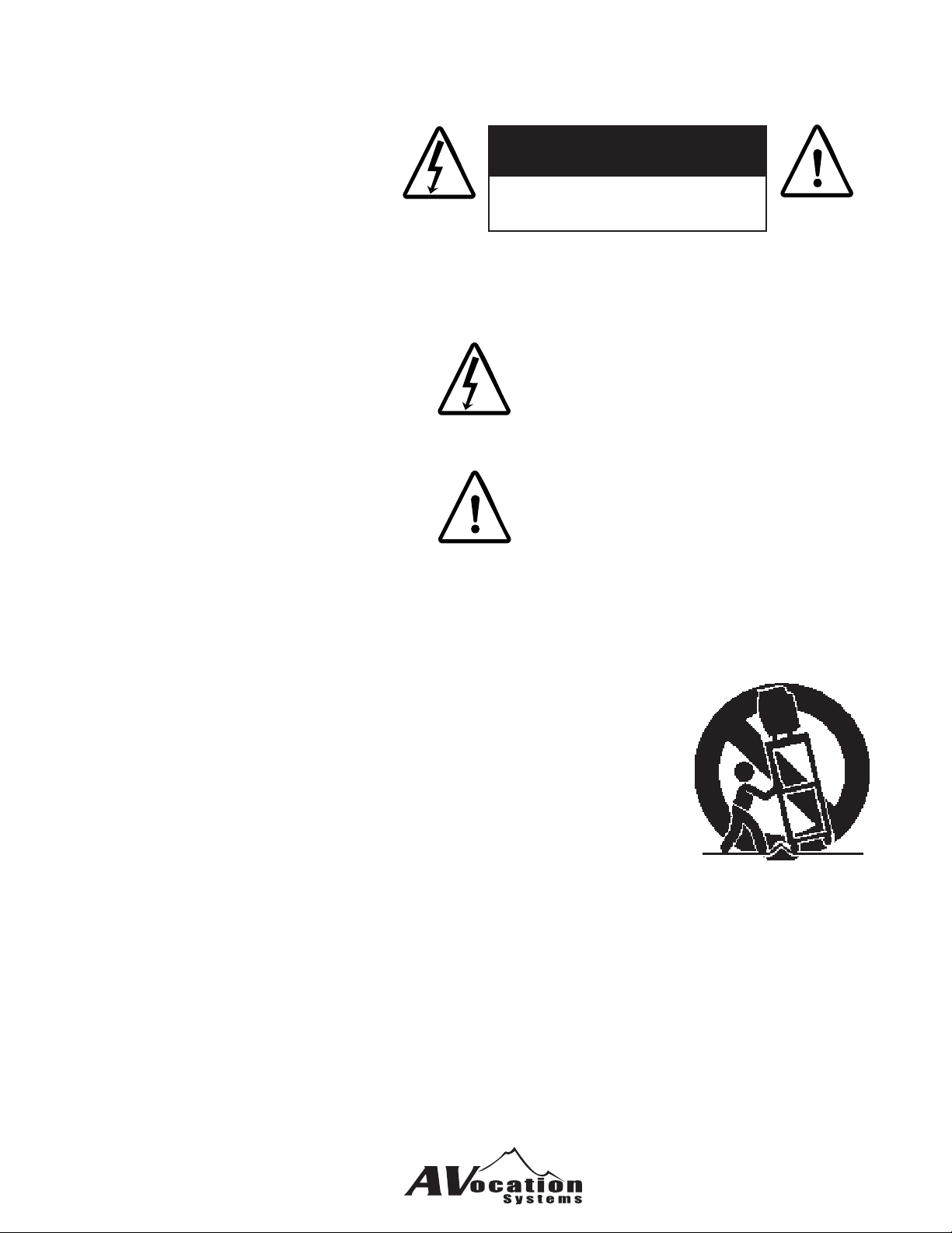
The lightning fl ash with arrowhead symbol, within
an equilateral triangle, is intended to alert you to the
presence of uninsulated "dangerous voltage" within
the product's enclosure that may be of suffi cient
magnitude to constitute a risk of electrical shock
to persons.
The exclamation point within an equilateral triangle
is intended to alert you to the presence of important
operating and maintenance (servicing) instructions
in the literature accompanying the appliance.
5 Water and Moisture - The appliance should not be used near water - for example, near
a bathtub, washbowl, kitchen sink, laundry tub, in a wet basement, or near a swimming
pool, etc.
6 Carts and Stands - The appliance should be used only with a
cart or stand that is recommended by the manufacturer.
6A An appliance and cart combination should be moved with care.
Quick stops, excessive force, and uneven surfaces may cause
the appliance and cart combination to overturn.
7 Wall or Ceiling Mounting - The appliance should be mounted to a wall or ceiling only
as recommended by the manufacturer.
8 Ventilation - The appliance should be situated so that its location or position does not
interfere with its proper ventalation. For example, the appliance should not be situated
on a bed, sofa, rug, or similar surface, that may block the ventilation openings; or placed
in a built-in installation, such as a bookcase or cabinet that may impede the fl ow of air
through the ventilation openings.
3
Page 4

9 Heat - The appliance should be situated away from heat sources such as radiators,
stoves, or other appliances that produce heat.
10 Power Sources - The appliance should be connected to a power supply only of the
type described in the operating instructions or as marked on the appliance.
11 Power-Cord Protection - Power-supply cords should be routed so that they are
not likely to be walked on or pinched by items placed upon or against them, paying
particular attention to cords at plugs, covenience receptacles, and the point where they
exit from the appliance.
12 Cleaning - The appliance should be cleaned only as recommended by the
manufacturer.
13 Nonuse Periods - The power cord of the appliance should be unplugged from the outlet
when left unused for a long period of time.
14 Object and Liquid Entry - Care should be taken so that objects do not fall into and
liquids are not spilled into the inside of the appliance.
15 Damage Requiring Service - The appliance should be serviced by qualifi ed service
personnel when:
A. The power-supply cord or the plug has been damaged.
B. Objects have fallen, or liquid has been spilled into the appliance.
C. The appliance has been exposed to rain.
D. The appliance does not appear to operate normally or exhibits a marked change in
performance.
E. The appliance has been dropped, or the cabinet is damaged.
16 Servicing - The user should not attempt to service the appliance beyond those means
described in the operating insturctions. All other serviing should be referred to qualifi ed
service personnel.
17 Power Lines - An outdoor antenna should be located away from power lines.
18 Grounding or Polarization - The precautions that should be taken so that the
grounding or polarization is not defeated.
4
Page 5

Be careful when unpacking the A/V Matrix and the Matrix Keypads. This electronic
package is susceptible to dropping or holding heavy objects on top of it. Save the original
package and all enclosed packing material in case the unit needs to be returned. Damage
due to shipping in cartons other than the original package are not covered under the
warranty.
Make sure you fi ll out and return the warranty card. This document along with the sales
receipt will give you the purchase date in case the unit needs to be returned for repair
under warranty service.
Any modifi cations or improper use of the A/V Matrix or the Matrix keypad will void the
warranty. Please read all information and instructions concerning this system before
installing.
For any questions or concerns about the A/V Matrix and/or the Matrix Keypads, please
call Avocation Systems, Inc. We are happy to answer any questions you may have or any
problems you may be experiencing. If you are unsure of any aspects of your installation
please contact one of our technicians before you start your installation. Avocation Systems,
Inc. we will assist you in any way we can.
Please read this manual carefully and completely before operating the A/V Matrix. It gives
details in operation, confi gurations, descriptions, adjustments, trouble shooting, problems,
performance, and convenience of use.
5
Page 6
Switching Sources Using the Front Panel
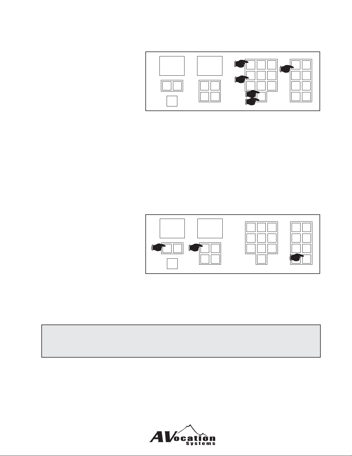
There are two ways to switch
audio and video inputs together
to an output
The fi rst way uses the A/V
button along with the keypad.
-
Input
Output
+
-
-
Volume
+
+
2b
1
456
3b
789
3a
2a
23
0
1) Press the A/V button
When this button is pressed, the input and output displays will go blank
2) Select the input number through the keypad such as 01 for input number 1
As you input the numbers they will show up on the Input LED
3) Select the output number through the keypad such as 04 for output number 4
As you input the numbers they will show up on the Output LED
The matrix will automatically enter this and switch input number 1 to output 4
The second method uses the Input and Output keys under the LED displays.
1) Select the output number
you wish to change by
pressing the - and + keys
under the Output LED
(the Input LED will show
the current input switched
to that output).
2) Select the input number
Input
2
-
+
Output
1
-
+
-
+
Volume
23
1
456
789
0
you wish to route to the
output by pressing the
- and + keys under the Input LED.
3) Press the Enter key to switch and save the selection.
1
A/V Func
Audio Preset
Video Cancel
Off Enter
A/V Func
Audio Preset
Video Cancel
3
Enter
Note:
If at any point you make an error, you can press the cancel button and start over.
7
Page 7
To switch audio to an output.
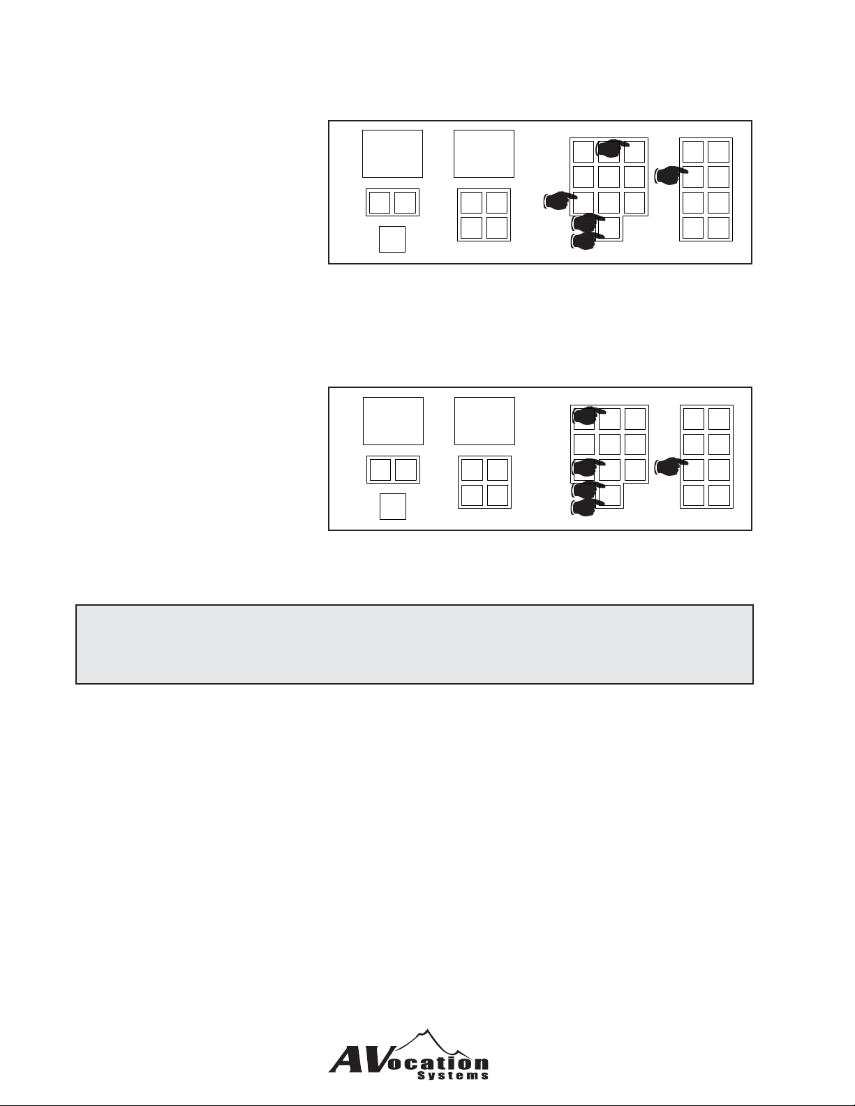
1) Press the Audio button
2) Select the input number
through the keypad such
-
Input
+
as 03 for input number 3
3) Select the output number
through the keypad such
as 07 for output number 7
The matrix will automatically
enter this and switch audio input number 3 to output 7.
To switch video only to an output.
1) Press the Video button
2) Select the input number
through the keypad such
-
Input
+
as 02 for input number 2
3) Select the output number
through the keypad such
as 08 for output number 8
Output
-
-
Volume
Output
-
-
Volume
2b
1
456
3b
+
+
+
+
789
3a
2a
2b
456
3b
3a
2a
3
0
23
89
0
1
1
A/V Func
Audio Preset
Video Cancel
Off Enter
A/V Func
Audio Preset
Video Cancel
Off Enter
The matrix will automatically
enter this and switch video input number 2 to output 8
Note:
If at any point you make an error, you can press the cancel button and start over.
8
Page 8
Teaching IR Matrix Control Commands
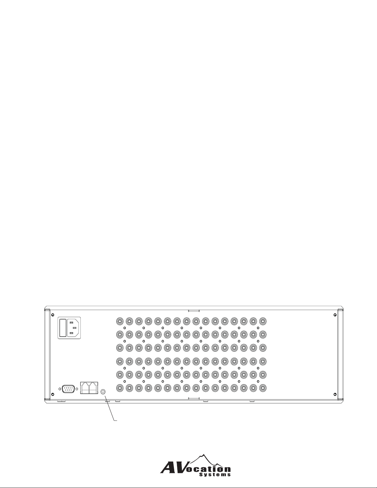
The Matrix can be controlled via IR commands taught through the IR Emitter Output.
Place an IRE (IR Emitter) into the connector and place the emitter on the learning device.
You must use the RS-232 port to tell the matrix to teach the IR commands. See the RS-232 section for ca-
bling and commands to use.
IRE Connection for teaching
IR commands
9
Page 9
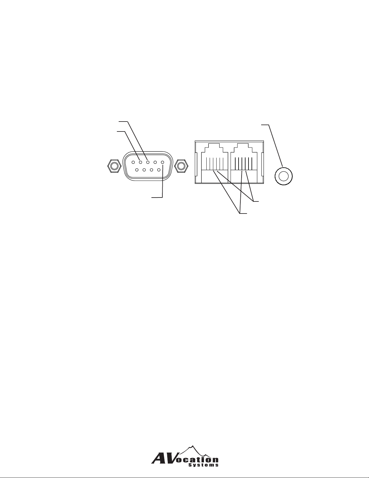
Section C - Control Connections
The MTX series of matrices can be controlled via RS-232, RS-485 and infrared.
RS-232 Connections to the matrix typically use a null modem cable from the controller.
The default communications parameters are:
Baud Rate 19200 baud
Bits 8
Parity None
Stop Bits 1
Transmit (Pin 3)
Receive (Pin 2)
Ground (Pin 5)
RS-485 communications use the same baud rate as RS-232. Both RJ-12 connectors are tied together to allow daisy
chained communications.
Infrared
Teaching
Output
Data+ (Pin 4)
Data- (Pin 3)
C11
Page 10
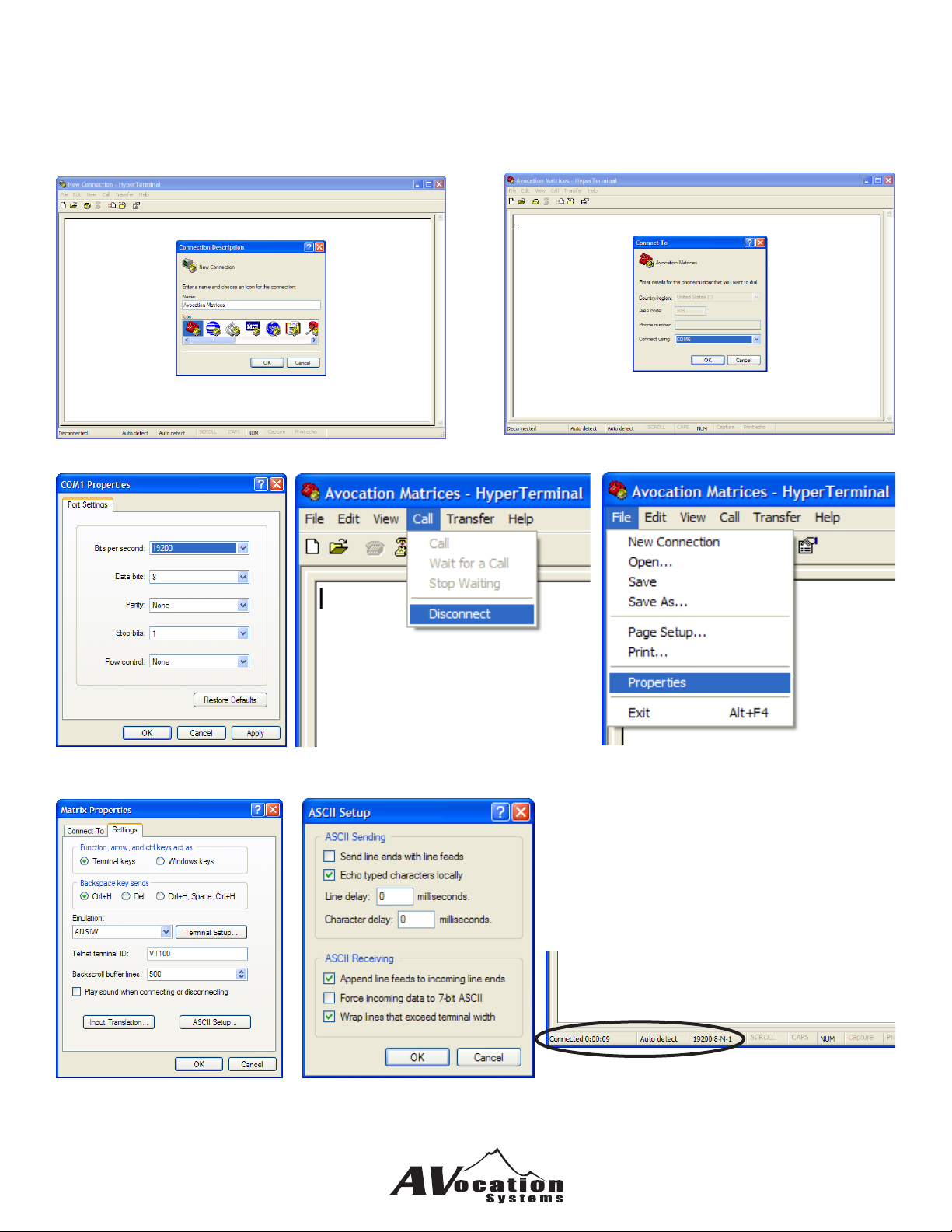
Using Windows Hyperterminal
The MTX Series is controllable through any terminal software such as Hyperterminal. The following setup can be used to
allow easy communications to the MTX unit.
1) Open Hyperterminal under Accessories => Communications => Hyperterminal
Provide a name for the connection and click OK.
Select the COM properties Disconnect Select File => Properties
Select the COM port to use
C12
Select the Settings Tab
Select ASCII Setup
Check “Echo typed characters locally” and
“Append line feeds to incoming line ends”
Select OK untill all the setup windows are
closed.
Hit “Enter” to make the connection.
Page 11
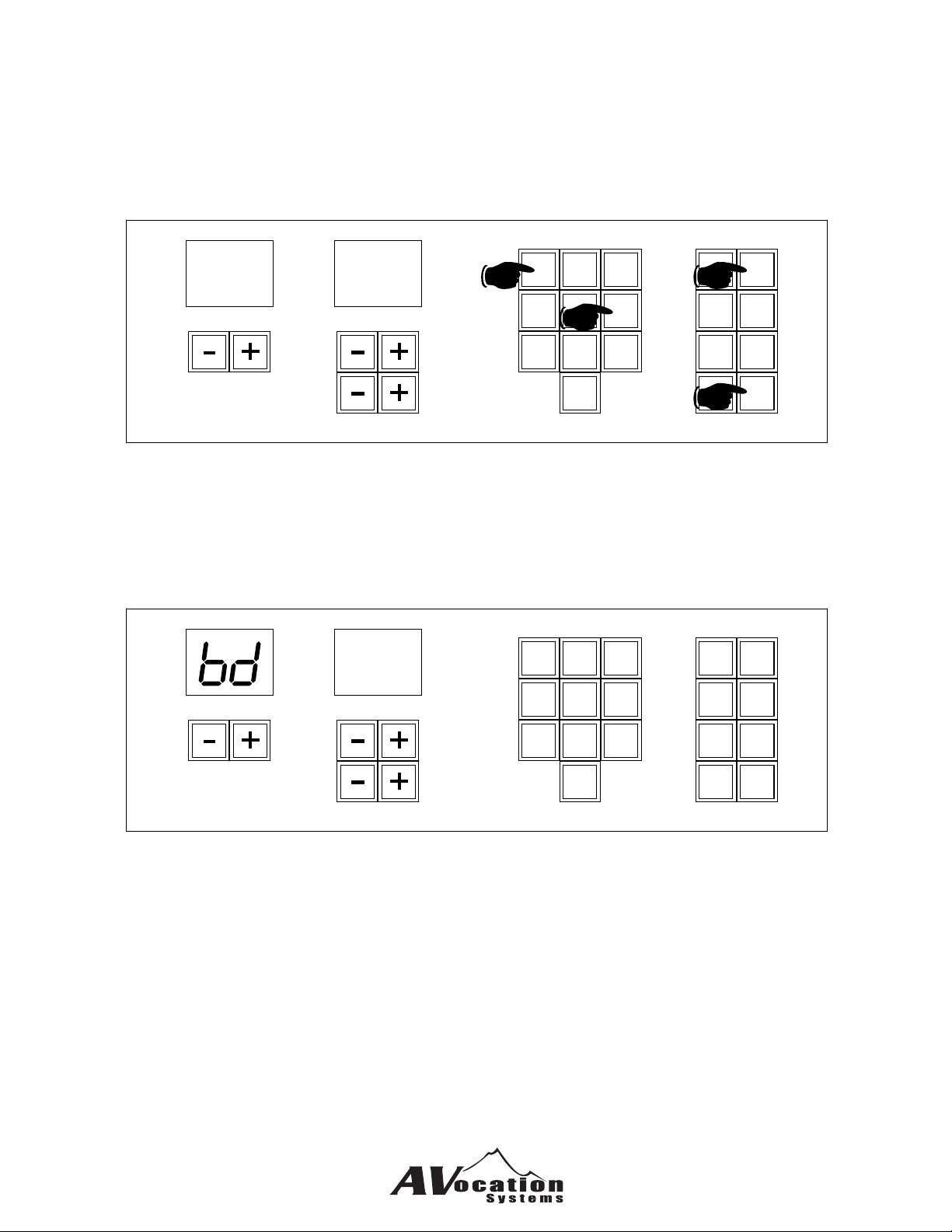
Changing the Units Baud Rate
The MTX baud rate for communications is changed through the the front panel by using the following keystrokes.
1) Press the “Func” button
2) Enter “6” and “1” then press “Enter”.
The display will show the current baud rate selected.
3) Enter the two digits for the baud rate that you want to select then press “Enter”.
Func
A/V
1
Audio
Video
Off
3
Preset
Cancel
Enter
Fc
Input
Valid baud rates are:
00 = 4800
01 = 9600
02 = 19200 (default)
03 = 38400
04 = 57600
05 = 115200
61
Output
Volume
2b
1
4
7
2
5
2a
8
0
3
6
9
2
1
02
4
7
5
8
0
Input
To change baud rates:
Enter the two digit code for the baud rate required and press Enter
Output
Volume
3
6
9
A/V
Audio
Video
Off
Func
Preset
Cancel
Enter
C13
Page 12

Section D - Commands
The Peak series of matrices have a number of commands for control and query to allow full control. Each command is
listed in this section with a description and example to help understand the commands.
The following commands are available:
Audio Routing and Status
MXxxAiioo .................................................... audio input to output ..................................................................A4
MXxxAiio1,o2,o3,o4,o5,o6,o7,o8 ................. audio input to multiple outputs ...................................................A4
MXxxAAii ...................................................... audio input to all outputs ............................................................A4
MXxxABooyy ................................................ balance ......................................................................................A4
MXxxABAyy .................................................. balance for all outputs ................................................................A4
MXxxAFoo .................................................... audio output off ..........................................................................A5
MXxxAMoo ................................................... audio mute (on, off, toggle) ........................................................A5
MXxxAPiiyy .................................................. Sensitivity ...................................................................................A5
MXxxAPAyy .................................................. all inputs to sensitivity yy ...........................................................A5
MXxxAUooyy ................................................ Volume to a paricular .................................................................A5
MXxxAUAyy ................................................. all outputs to volume level yy .....................................................A6
MXxxAYoo .................................................... Volume step up ..........................................................................A6
MXxxAZoo .................................................... Volume step down .....................................................................A6
MXxxSA(oo) ................................................. status of audio route (s) .............................................................A6
MXxxSAA ..................................................... status of all audio items
MXxxSAB(oo) ............................................... status of audio balance(s)
MXxxSAM(oo) .............................................. status of of audio mute(s)
MXxxSAP(ii) ................................................. status of sensitivity level(s)
MXxxSAU(oo) ............................................... status of volume level(s)
MXxxZ50ooyy............................................... set maximum volume for output
MXxxZ51 ...................................................... read all maximum volume settings
MXxxZ57y .................................................... set volume enable
MXxxZ58 ...................................................... read volume enable
MXxxZ59y .................................................... set sensitivity enable
MXxxZ60 ...................................................... read sensitivity enable
Video Routing and Status
MXxxViioo .................................................... Video input to output
MXxxViio1,o2,o3,o4,o5,o6,o7,o8 ................. video input to multiple outputs
MXxxVFoo .................................................... video output off
MXxxVAii ...................................................... route video input to all outputs
MXxxSV(oo) ................................................. status of video route(s)
Digital Audio Routing and Status
MXxxDiioo .................................................... Digital input to output
MXxxDiio1,o2,o3,o4,o5,o6,o7,o8 ................. input to multiple outputs
MXxxDAii ...................................................... send Digital input to all
MXxxDFoo .................................................... Digital output off
MXxxSD(oo) ................................................. status of digital route(s)
Audio/Video/Digital Routing and Status
MXxxBiioo .................................................... A/D/V input to output
MXxxBiio1,o2,o3,o4,o5,o6,o7,o8 ................. input to multiple outputs
MXxxBAii ...................................................... send A/D/V input to all
MXxxBFoo .................................................... A/D/V output off
MXxxBS ........................................................ A/D/V straight through
MXxxSB(oo) ................................................. status of A/D/V route(s)
D18
Page 13

General Status
MXxxS .......................................................... all status returned
Conguration Commands
MXxxZ01 ...................................................... read audio inputs
MXxxZ02 ...................................................... read video inputs
MXxxZ03 ...................................................... read audeo outputs
MXxxZ04 ...................................................... read video outputs
MXxxZ05 ...................................................... read option ags
MXxxZ06 ...................................................... read hardware type (model number)
MXxxZ07 ...................................................... read hardware code
MXxxZ08 ...................................................... read hardware revision
MXxxZ09 ...................................................... read software revision
MXxxZ10 ...................................................... read serial number
MXxxZ11 ...................................................... read mfg date
MXxxZ13 ...................................................... set/read enable/disable front panel control
MXxxZ17 ...................................................... set/read volume mode
MXxxZ18 ...................................................... set/read mute release mode
MXxxZ21 ...................................................... set/read response mode
MXxxZ53 ...................................................... Set/Read select digital with analog
MXxxZ54 ...................................................... Set/Read select digital with video
D19
Page 14

IR Teaching Commands
MXxxZ52 ...................................................... Teach IR code
MXxxZ56vv ................................................... Set/read number of times to repeat on IR teaching
Preset Commands
MXxxZ23yy ................................................... set preset name
MXxxZ24yy ................................................... read preset name
MXxxZ25yy ................................................... clear preset name
MXxxZ26xxyyiioo ......................................... set audio preset
MXxxZ27xxyy ............................................... read audio preset
MXxxZ28xxyy ............................................... clear audio preset
MXxxZ29xxyyiioo ......................................... set digital preset
MXxxZ30xxyy ............................................... read digital preset
MXxxZ31xxyy ............................................... clear digital preset
MXxxZ32xxyyiioo ......................................... set video preset
MXxxZ33xxyy ............................................... read video preset
MXxxZ34xxyy ............................................... clear video preset
MXxxZ35xxyyiioo ......................................... set A/D/V preset
MXxxZ36xxyy ............................................... read A/D/V preset
MXxxZ37xxyy ............................................... clear A/D/V preset
MXxxZ38xxyyiioo ......................................... set volume Preset
MXxxZ39iioo................................................. read volume Preset
MXxxZ40ooyy............................................... clear volume Preset
MXxxZ41xxyyiioo ......................................... set balance Preset
MXxxZ42iioo................................................. read balance Preset
MXxxZ43ooyy............................................... clear balance Preset
MXxxZ44xxyyiioo ......................................... set Sensitivity Preset
MXxxZ45ooyy............................................... read Sensitivity Preset
MXxxZ46ooyy............................................... clear Sensitivity Preset
MXxxZ47pp .................................................. Save current setup as preset no. pp
MXxxZ48xx ................................................... read complete preset
MXxxZ49xx ................................................... run preset number xx
MXxxZ98 ...................................................... reset unit
MXxxZ99 ...................................................... search for unit
D20
Page 15
Legend:
xx = unit ID number 00 to 15
ii = input number 00 to 64
oo = output number 01 to 64
yy = value to set
Audio Routing Commands
MXxxAiioo<CR>
Route an audio input to an audio output MX00A0103<CR>
Routes audio input 1 to output 3
Response: MXxx-Audio=ii to oo<CR>
MXxxAiio1,o2,o3,o4,o5,o6,o7,o8<CR>
Route an audio input to as many as 10 outputs MX00A0101,02,03,04,05,06,07,08,09,10<CR>
Routes audio input 1 to outputs 1 to 8
MX00A0101,02,03,04<CR>
Routes audio input 1 to outputs 1 to 4
Response: MXxx-Audio=ii to oo<CR> (for each route made)
MXxxAAii<CR>
Routes an audio input to all outputs MX00AA02<CR>
Routes audio input 2 to all audio outputs
Response: MXxx-Audio=ii to oo<CR> (for each route made)
MXxxABooyy<CR
Sets a balance level for an output MX00AB0249<CR>
yy=00 for full left
yy=49 for center
yy=99 full right
Output 2 is set for equal balance between left and right
channels.
Response: MXxx-Balance oo set to yy<CR>
MXxxAFoo<CR>
Turn an audio output off MX00AF03<CR>
Turn off audio output number 3
Response: MXxx-Audio=00 to oo<CR>
D21
Page 16
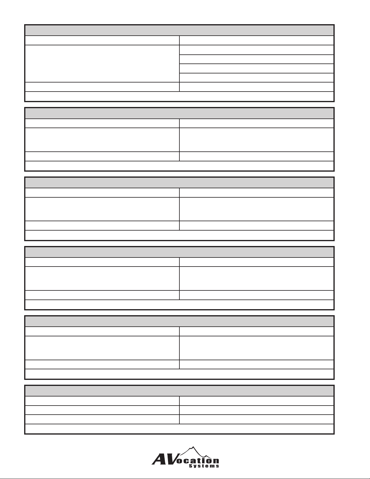
MXxxAMoo(y)<CR>
Mute an audio output MX00AM03<CR>
absence of (y) will result in a toggle of the mute
adding (y) is optional for setting a mute directly
y = 0 turns off the mute for the output
y = 1 turn on the mute for the output
Toggle the mute of output 3
MX00AM021<CR>
Enables the mute for output 2
Response: MXxx-Audio=00 to oo<CR> (for each route made)
MXxxAPiiyy<CR>
Set the level adjustment for an audio input MX00AP0132<CR>
yy = 00 to 48
yy = 32 for 0dB pass
yy adjusts in 0.5dB steps
Sets audio input 1 to 0dB pass
Response: MXxx-Sensitivity ii set to yy<CR>
MXxxAPAyy<CR>
Set the level adjustment for all audio inputs MX00APA32<CR>
yy = 00 to 48
yy = 32 for 0dB pass
yy adjusts in 0.5dB steps
Sets all audio inputs to 0dB pass
Response: MXxx-Sensitivity ii set to yy<CR> (for each input changed)
MXxxAUooyy<CR>
Sets an audio output volume level MX00AU0132<CR>
yy = 00 (-64dB Minimum)
yy = 32 (0dB Pass Through)
yy = 48 (+32dB Maximum)
Sets audio output 1 to 0dB pass
Response: MXxx-Volume oo to yy<CR>
MXxxAUAyy<CR>
Sets all audio outputs to a volume level MX00AUA32<CR>
yy = 00 (-64dB Minimum)
yy = 32 (0dB Pass Through)
yy = 48 (+32dB Maximum)
Sets all audio outputs 1 to 0dB pass
Response: MXxx-Volume oo to yy<CR> (for each output changed)
MXxxAYoo<CR>
Step an audio output volume up one level MX00AY03<CR>
Step up audio output number 3 up one step
Response: MXxx-Volume oo to yy<CR>
D22
Page 17
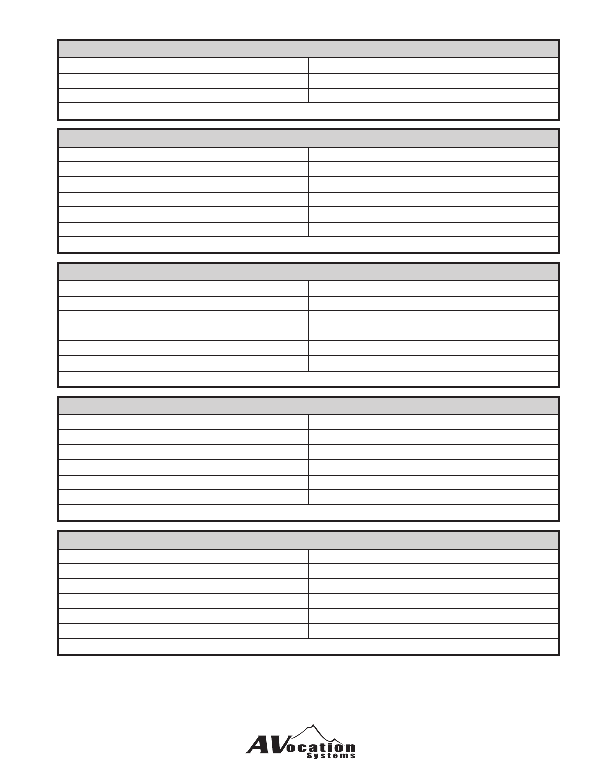
MXxxAZoo<CR>
Step an audio output volume down one level MX00AY03<CR>
Step down audio output number 3 up one step
Response: MXxx-Volume oo to yy<CR>
MXxxSA(oo)<CR>
Query for the status of an audio route. MX00SA<CR>
Returns the status of all the audio routes
MX00SA04<CR>
Returns the routing status of audio output number 4
Response: MXxx-Audio=ii to oo<CR> (each output will be sent if output number not specied)
MXxxSAB(oo)<CR>
Query for the status of an audio output balance MX00SAB<CR>
Returns the balance status of all the audio outputs
MX00SAB04<CR>
Returns the balance status of audio output number 4
Response: MXxx-Balance oo set to yy<CR> (each output will be sent if output number not specied)
MXxxSAM(oo)<CR>
Query for the mute status of an audio output MX00SAM<CR>
Returns the mute status of all the audio outputs
MX00SAM04<CR>
Returns the mute status of audio output number 4
Response: MX00-Output 01 is Muted<CR> (each output will be sent if output number not specied)
MXxxSAP(oo)<CR>
Query for the status of an audio input level MX00SAP<CR>
Returns the level of all the audio inputs
MX00SAP04<CR>
Returns the level of audio input number 4
Response: MXxx-Sensitivity ii set to yy<CR> (each input will be sent if input number not specied)
D23
Page 18
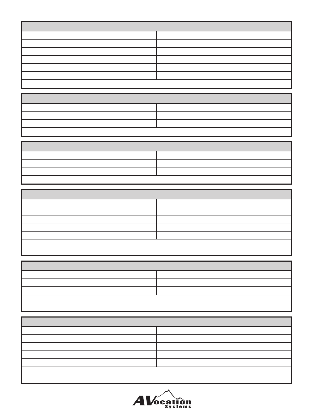
MXxxSAU(oo)<CR>
Query for the status of an audio output volume MX00SAP<CR>
Returns the volume of all the audio outputs
MX00SAP04<CR>
Returns the volume of audio output number 4
Response: MXxx-Volume oo to yy<CR> (each output will be sent if output number not specied)
MXxxZ50ooyy<CR>
Set the maximum volume level for an output MX00Z500432<CR>
yy=00 to 48 Set the maximum volume for output 4 to 32
Response: MXxx-Max Out Level for oo = yy<CR>
MXxxZ51<CR>
Read the maximum volume level for all outputs MX00Z51<CR>
Read all output maximum volume levels
Response: MXxx-Max Out Level for oo = yy<CR> (each output will be sent)
MXxxZ57y<CR>
Enable/Disable volume control MX00Z570<CR>
y=0 to disable volume control Disable volume control in the matrix
y=1 to enable volume control
MX00Z571<CR>
Enable volume control in the matrix
Response: MXxx-Volume control enabled<CR>
Response: MXxx-Volume control disabled<CR>
MXxxZ58<CR>
Read volume control enable/disable status MX00Z58<CR>
Get the status of volume control ability
Response: MXxx-Volume control enabled<CR>
Response: MXxx-Volume control disabled<CR>
MXxxZ59y<CR>
Enable/Disable sensitivty control MX00Z590<CR>
y=0 to disable sensitivty control Disable sensitivty control in the matrix
y=1 to enable sensitivty control
MX00Z591<CR>
Enable sensitivty control in the matrix
Response: MXxx-Sensitivity control enabled<CR>
Response: MXxx-Sensitivity control disabled<CR>
D24
Page 19
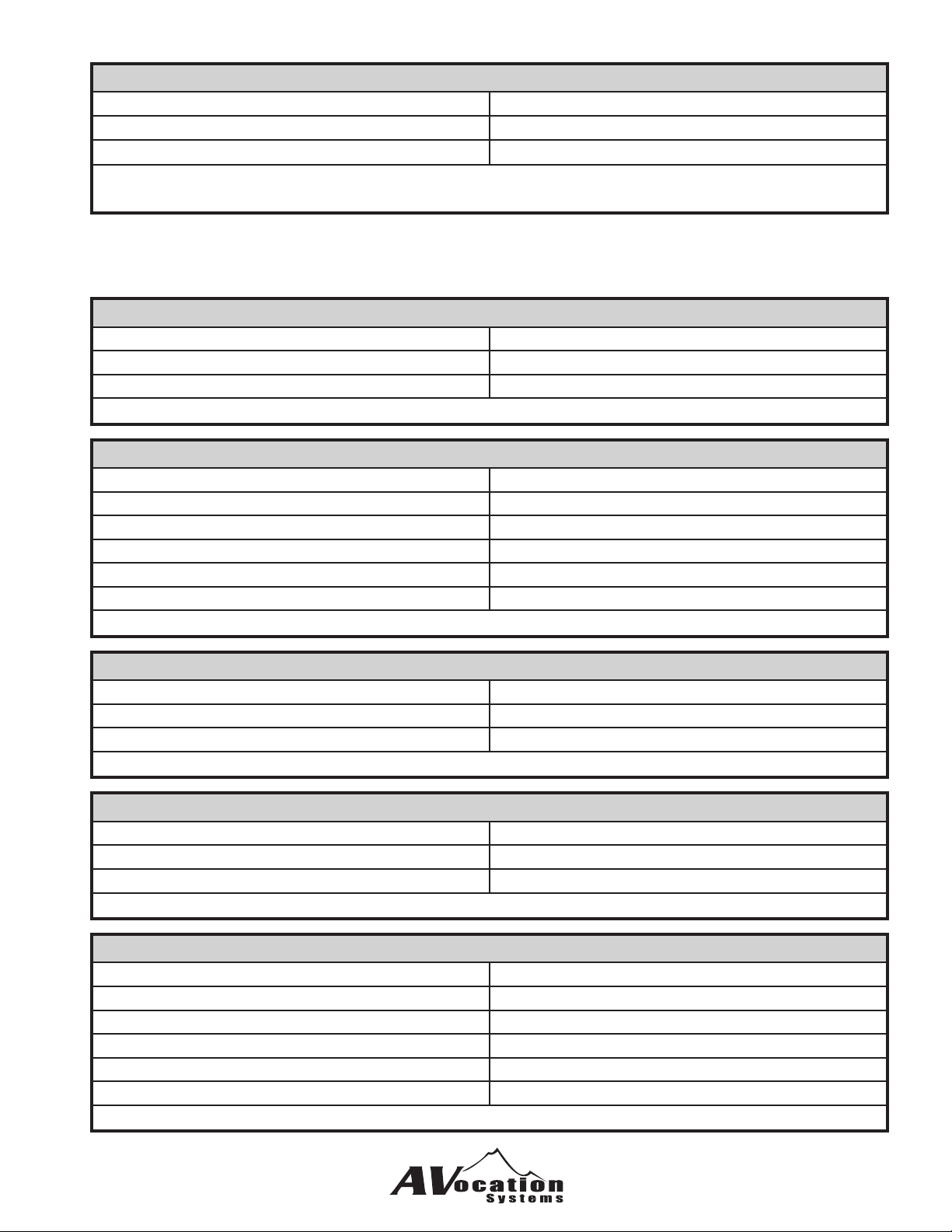
MXxxZ60<CR>
Read sensitivty control enable/disable status MX00Z60<CR>
Get the status of sensitivty control ability
Response: MXxx-Sensitivity control enabled<CR>
Response: MXxx-Sensitivity control disabled<CR>
Video Routing Commands
MXxxViioo<CR>
Route a video input to an video output MX00V0103<CR>
Routes video input 1 to output 3
Response: MXxx-Video=ii to oo<CR>
MXxxViio1,o2,o3,o4,o5,o6,o7,o8,o9,o10<CR>
Route an video input to as many as 10 outputs MX00V0101,02,03,04,05,06,07,08,09,10<CR>
Routes video input 1 to outputs 1 to 10
MX00V0101,02,03,04<CR>
Routes video input 1 to outputs 1 to 4
Response: MXxx-Video=ii to oo<CR> (for each route made)
MXxxVAii<CR>
Routes a video input to all outputs MX00VA02<CR>
Routes video input 2 to all video outputs
Response: MXxx-Video=ii to oo<CR> (for each route made)
MXxxVFoo<CR>
Turn a video output off MX00VF03<CR>
Turn off video output number 3
Response: MXxx-Video=00 to oo<CR>
MXxxSV(oo)<CR>
Query for the status of a video route. MX00SV<CR>
Returns the status of all the video routes
MX00SV04<CR>
Returns the routing status of video output number 4
Response: MXxx-Video=ii to oo<CR> (each output will be sent if output number not specied)
D25
Page 20
Digital Routing Commands
MXxxDiioo<CR>
Route an digital input to an a/v output MX00D0103<CR>
Routes digital input 1 to output 3
Response: MXxx-Digital=ii to oo<CR>
MXxxDiio1,o2,o3,o4,o5,o6,o7,o8,o9,o10<CR>
Route an digital input to as many as 10 outputs MX00D0101,02,03,04,05,06,07,08,09,10<CR>
Routes digital input 1 to outputs 1 to 10
MX00D0101,02,03,04<CR>
Routes digital input 1 to outputs 1 to 4
Response: MXxx-Digital=ii to oo<CR> (for each route made)
MXxxDAii<CR>
Routes an a/v input to all outputs MX00DA02<CR>
Routes digital input 2 to all digital outputs
Response: MXxx-Digital=ii to oo<CR> (for each route made)
MXxxDFoo<CR>
Turn an digital output off MX00DF03<CR>
Turn off digital output number 3
Response: MXxx-Digital=00 to oo<CR>
MXxxSD(oo)<CR>
Query for the status of an digital route. MX00SD<CR>
Returns the status of all the digital routes
MX00SD04<CR>
Returns the routing status of digital output number 4
Response: MXxx-Digital=ii to oo<CR> (each output will be sent if output number not specied)
MXxxZ53(y)<CR>
Set/Read select digital with analog MX00Z530<CR>
y = 0 digital will not switch with analog audio Disconnect digital from routing with analog audio
y = 1 digital will switch with analog audio
if y is not used the current setting will be returned
Response: MXxx-Digital will not switch with audio<CR>
D26
Page 21
MXxxZ54(y)<CR>
Set/Read select digital with video MX00Z541<CR>
y = 0 digital will not switch with video Disconnect digital from routing with video
y = 1 digital will switch with video
if y is not used the current setting will be returned
Response: MXxx-Digital will switch with video<CR>
A/V Routing Commands
MXxxBiioo<CR>
Route an a/v input to an a/v output MX00B0103<CR>
Routes a/v input 1 to output 3
Response: MXxx-A/V=ii to oo<CR>
MXxxBiio1,o2,o3,o4,o5,o6,o7,o8,o9,o10<CR>
Route an a/vinput to as many as 10 outputs MX00B0101,02,03,04,05,06,07,08,09,10<CR>
Routes a/v input 1 to outputs 1 to 10
MX00B0101,02,03,04<CR>
Routes a/v input 1 to outputs 1 to 4
Response: MXxx-A/V=ii to oo<CR> (for each route made)
MXxxBAii<CR>
Routes an a/v input to all outputs MX00BA02<CR>
Routes a/v input 2 to all video outputs
Response: MXxx-A/V=ii to oo<CR> (for each route made)
MXxxBFoo<CR>
Turn an a/v output off MX00BF03<CR>
Turn off a/v output number 3
Response: MXxx-A/V=00 to oo<CR>
MXxxSB(oo)<CR>
Query for the status of an a/v route. MX00SB<CR>
Returns the status of all the a/v routes
MX00SB04<CR>
Returns the routing status of a/v output number 4
Response: MXxx-A/V=ii to oo<CR> (each output will be sent if output number not specied)
D27
Page 22
Conguration Commands
MXxxZ01<CR>
Query how many audio inputs installed MX00Z01<CR>
Query how many audio inputs are installed
Response: MXxx-Audio inputs = yy<CR>
MXxxZ02<CR>
Query how many video inputs installed MX00Z02<CR>
Query how many video inputs are installed
Response: MXxx-Video inputs = yy<CR>
MXxxZ03<CR>
Query how many audio outputs installed MX00Z03<CR>
Query how many audio outputs are installed
Response: MXxx-Audio outputs = yy<CR>
MXxxZ04<CR>
Query how many video outputs installed MX00Z04<CR>
Query how many video outputs are installed
Response: MXxx-Video outputs = yy<CR>
MXxxZ06<CR>
Query matrix model number MX00Z06<CR>
Query for the model number of the matrix
Response: MXxx-Model No. = MX-0808NAD/R<CR>
MXxxZ07<CR>
Query for the matrix hardware level MX00Z07<CR>
Query for the hardware level in the matrix
D28
Response: MXxx-Hardware Code = MTX-1616-B<CR>
Page 23
MXxxZ08<CR>
Query matrix hardware revision level MX00Z08<CR>
Query how many video outputs are installed
Response: MXxx-Hardware revision = 1.000<CR>
MXxxZ09<CR>
Query for the matrix software revision level MX00Z09<CR>
Query for the software level in the matrix
Response: MXxx-Software revision = 1.000<CR>
MXxxZ10<CR>
Query for the matrix serial number MX00Z10<CR>
Query for the serial number of the matrix
Response: MXxx-Serial No. = MTX09B1000<CR>
MXxxZ13y<CR>
Enable/Disable front panel controls MX00Z131<CR>
y = 0 for disable Enables front panel controls (default mode)
y = 1 for enable
Response: MXxx-Front Panel is (locked/unlocked)<CR>
MXxxZ17y<CR>
Set volume mode to linear or logarithmic MX00Z251<CR>
y = 0 for linear Sets volume to logarithmic mode (default mode)
y = 1 for logarithmic
Response: MXxx-Volume is Logarithmic<CR>
MXxxZ18y<CR>
Set mute release on volume change MX00Z251<CR>
y = 0 to keep mute on when volume is changed Sets mute release to on (default mode)
y = 1 to turn mute off when volume is changed
Response: MXxx-Mute Release is (Enabled/Disabled)<CR>
D29
Page 24

11
 Loading...