

Page 1
ZedBoard
(Zynq™ Evaluation and Development)
Configuration and Booting Guide
Version 1.1
August 2012
Page 2

ZedBoard Booting and Configuration Gui de ISE Design Suite 14.1
TableofContents
Introduction ......................................................................................................................... 2
Reference Design Requirements ......................................................................................... 2
Software .......................................................................................................................... 2
Hardware ......................................................................................................................... 2
Hardware Design Block Diagram ....................................................................................... 3
Supplied Files...................................................................................................................... 4
First Things First ................................................................................................................. 5
Setting Up the ZedBoard Development Board ............................................................... 5
Extract the Zip File ......................................................................................................... 6
PC Setup.......................................................................................................................... 6
Installing the UART Driver and Virtual COM Port ................................................... 6
Installing a Serial Console on a Windows 7 Host ....................................................... 6
JTAG Configuration Mode ................................................................................................. 7
Application Download .................................................................................................... 7
GPIO Test Demo............................................................................................................. 9
SDK Software Tasks ......................................................................................................... 10
Create the SDK Workspace .......................................................................................... 10
Create the Board Support Package ............................................................................... 14
Import the GPIO Test Software Application ................................................................ 16
Running the GPIO Test Software Application ............................................................. 18
Create the First Stage Boot Loader ............................................................................... 23
Create the Boot Image .................................................................................................. 24
Booting From the SD Card ............................................................................................... 26
Prepare the SD Card ...................................................................................................... 26
GPIO Test Demo........................................................................................................... 27
Booting From QSPI Flash ................................................................................................. 28
Program the QSPI Flash................................................................................................ 28
GPIO Test Demo........................................................................................................... 36
Where to Get More Information ....................................................................................... 37
ZedBoard Website ........................................................................................................ 37
Xilinx Website .............................................................................................................. 37
Revision History ............................................................................................................... 37
1
Page 3

ZedBoard Booting and Configuration Gui de ISE Design Suite 14.1
Introduction
This document provides an introduction to the available configuration and processor boot
modes of the Avnet ZedBoard development board. The example design used in this
guide is a basic ZynqTM -7000 All Programmable SoC design implemented and tested on
the Avnet ZedBoard development board. For more information about this provided
design or to build it for yourself please consult the ZedBoard: Zynq-7000 EPP Concepts,
Tools, and Techniques hands-on guide found at www.zedboard.org/design. Using this
example design this guide will show you how to use the JTAG configuration mode of the
ZedBoard as well as how to boot the processor and configure the programmable logic of
the Zynq-7000 device using the SD card and QSPI boot modes. The tasks performed in
this guide follow a logical progression such that it is expected that users will start at the
beginning and work their way toward the end.
Reference Design Requirements
Software
The software requirements for this reference design are:
Linux, Windows XP, Windows 7
(www.xilinx.com/ise/ossupport/index.htm)
Xilinx ISE Design Suite 14.1, with PlanAhead and SDK
Hardware
The hardware setup for this reference design is:
Computer with 1.1 GB RAM and 1.1 GB virtual memory (recommended)
(www.xilinx.com/ise/products/memory.htm)
Avnet ZedBoard development board
USB-A to micro-B cables
o UART
o JTAG
Power supply (12V)
2
Page 4
ZedBoard Booting and Configuration Gui de ISE Design Suite 14.1
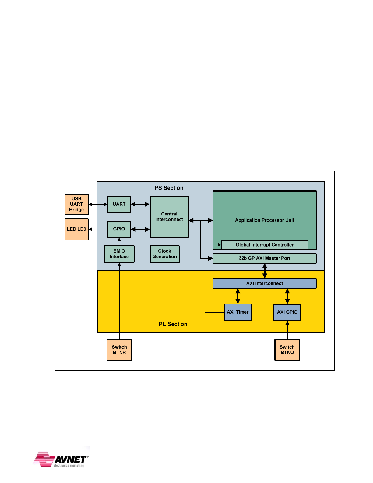
Hardware Design Block Diagram
The hardware platform for this guide is based on the Processor System (PS) configuration
and Programmable Logic (PL) bitstream described in the ZedBoard: Zynq-7000 EPP
Concepts, Tools, and Techniques hands-on guide found at www.zedboard.org/design.
The following figure shows a high-level block diagram of the hardware design. The
design requires:
Z7020 Zynq-7000 AP SoC
512MB DDR3 SDRAM
256Mbit QSPI Flash
USB UART Bridge Serial Port
LEDs and push button switches
Timer
Figure 1 – Reference Design Block Diagram
3
Page 5

ZedBoard Booting and Configuration Gui de ISE Design Suite 14.1
Supplied Files
The following directory structure is included with this reference design:
boot_image: Empty folder to use to create new BOOT.BIN boot image.
demo: Contains the script files, boot image, and application executables:
BOOT.BIN: Boot image of First Stage Boot Loader (FSBL), PL bistream, and
GPIO test application.
bootimage.bif: Boot image information text file.
cp_from_sdk.bat: Batch file to copy hardware bitstream and software
executables from the SDK workspace.
gpio_test_0.elf: The golden ARM executable for the GPIO test application.
load_bits.tcl: TCL script to load the PL bitstream via XMD.
make_bootbin.bat: Batch file to run the command to create the boot image file.
ps7_init.tcl: TCL script to initialize the ARM processor.
run_gpio_test.bat: Batch file to run the commands to load the PL bitstream of
the hardware design, initialize the processor, and download the GPIO test
application.
run_uboot.bat: Batch file to run the commands to initialize the processor and
download the u-boot application.
system.bit: The golden FPGA bitstream of the hardware design required to run
the GPIO test application.
u-boot_autoboot_disabled.elf: The golden ARM executable for the u-boot
application used to program the QSPI Flash.
xmd.ini: Command file used by XMD to configure the PL with the hardware
bitstream, initialize the processor, and download the software applications.
zynq_fsbl_0.elf: The golden ARM executable for the Zynq FSBL.
doc: Contains documentation for this design:
ZedBoard_boot_guide_IDS14_1_v1_1.pdf: This document.
pa: Contains the PlanAhead hardware project and SDK workspace files and folders.
SDK_sw: Contains the GPIO test software application source files.
boot_image_golden.zip: Contains pre-built BOOT.BIN boot image for this design.
demo_golden.zip: Contains the golden copies of the files in the demo folder.
4
Page 6
Power
SW8
UART
ZedBoard Booting and Configuration Gui de ISE Design Suite 14.1
First Things First
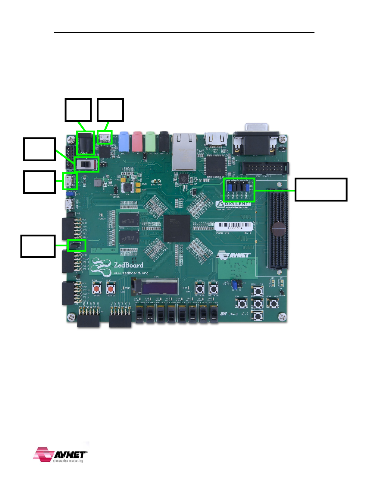
Setting Up the ZedBoard Development Board
Refer to the following figure and perform the following steps to set up the board for
running the applications.
12V
J20
JTAG
J17
Configuration
ModePins
MIO[0]
Figure 2 - ZedBoard Development Board
1. Verify a jumper is installed on JP6 to enable the processor to boot from the SD card.
2. Plug a USB cable into the PC and the JTAG micro-B USB connector (J17).
3. Plug a USB cable into the PC and the UART micro-B USB connector (J14).
4. Plug the 12V power supply into the barrel jack (J20). Do not turn the board on.
5
Page 7
ZedBoard Booting and Configuration Gui de ISE Design Suite 14.1
Extract the Zip File
Since you are reading this guide you have probably already extracted the zip file
associated with this tutorial guide. Using Windows™ Explorer navigate to the folder
where the zip file was extracted (<installation> folder). Make sure there are NO
SPACES in this path. The Xilinx SDK, which is used later in this guide, does not
tolerate spaces in this file path.
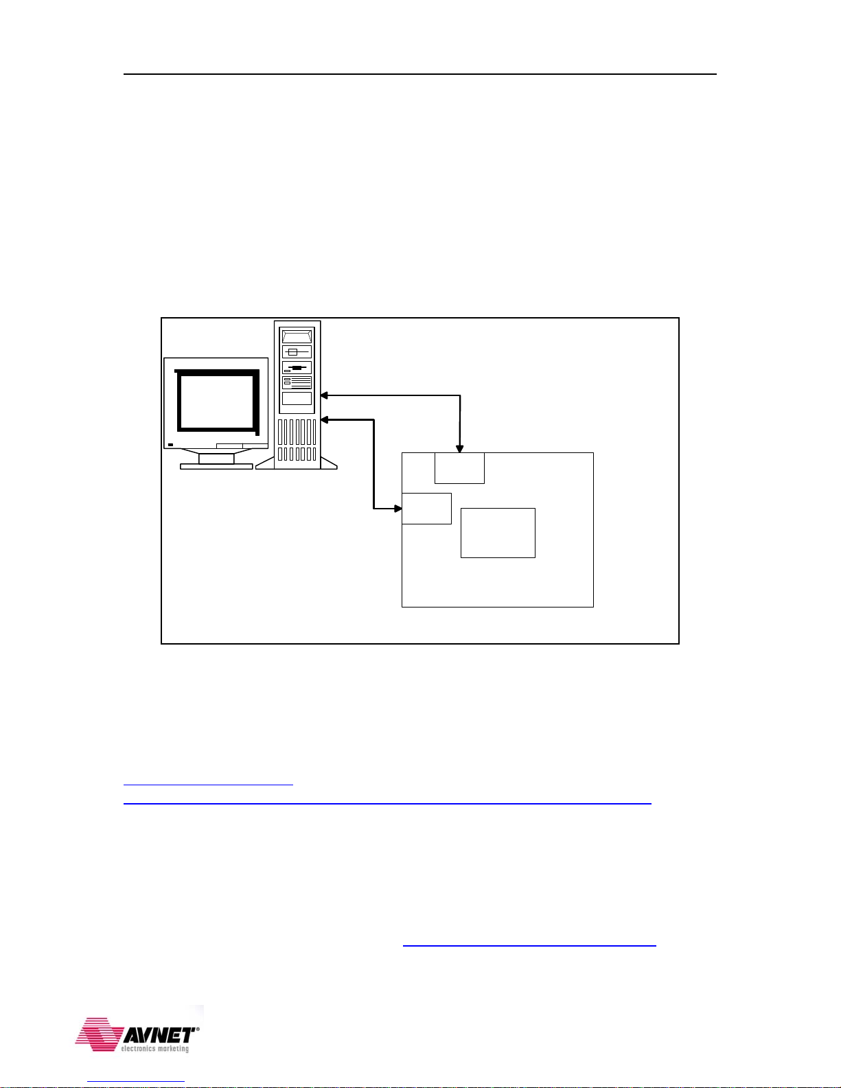
PC Setup
Follow the figure below to connect the ZedBoard to the development host PC to establish
the USB connections for the UART and JTAG programming.
USB Cable (JTAG)
USB Cable (UART)
Micro
PC
USB-B
Micro
USB-B
Zedboard Development Board
Zynq
Z7020
AP SOC
Figure 3 – Board Connection Setup
Installing the UART Driver and Virtual COM Port
If the ZedBoard development board has not been connected to the host PC before, it may
be necessary to install the software driver for the virtual COM port. The driver
installation for the Cypress CY7C64225 USB-UART bridge is described in detail in the
CY7C64225 Setup Guide available at
http://www.zedboard.org/sites/default/files/CY7C64225_Setup_Guide_1_1.pdf.
Installing a Serial Console on a Windows 7 Host
Starting with Windows 7, Microsoft no longer includes the HyperTerminal terminal
emulator software. However, this example design requires use of terminal emulation
software for a serial console connection to the ZedBoard Development Board. A suitable
free and open-source replacement for HyperTerminal is TeraTerm. Download and install
instructions for TeraTerm can be found at http://en.sourceforge.jp/projects/ttssh2. As an
alternative the Terminal applet in the Xilinx SDK may also be used.
6
Page 8
ZedBoard Booting and Configuration Gui de ISE Design Suite 14.1
JTAG Configuration Mode
You can load the FPGA and run the example software application without building the
design by using the demo scripts and the pre-built hardware bitstream and software
application elf files. You must have the Xilinx tools installed on your host, and have the
hardware set up and connected as per the previous steps.
Application Download
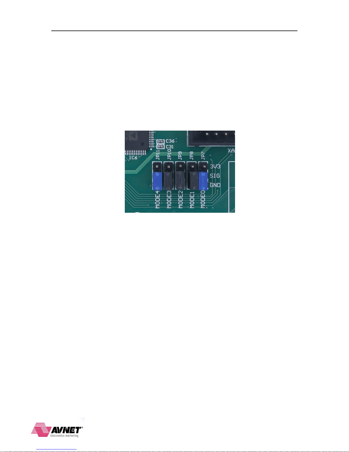
1. Verify the ZedBoard is powered off and that the configuration Mode jumpers are set
for JTAG mode (all pins shunted to GND) as in the figure below:
2. Slide the power switch (SW8) to the ON position. You will see the green ‘power
good’ LED (LD13) illuminate.
3. Navigate to Control Panel Device Manager Ports (COM & LPT) and identify
the COM port connected to the ZedBoard. Start a serial terminal session for the
identified COM port and set the serial port parameters to 115200 baud rate, no parity,
8 bits, 1 stop bit and no flow control.
4. Open a command window in the <installation>\demo folder and enter:
run_gpio_test.bat
This batch file sets the proper environment variables and creates the xmd.ini script of
commands to be used by the Xilinx Microprocessor Debugger (XMD) tool to
program the PL bitstream, initialize the processor, download the application code, and
begin execution on the system by performing the following commands automatically:
source load_bits.tcl
connect arm hw
source ps7_init.tcl
ps7_init
dow gpio_test_0.elf
run
exit
7
Page 9
ZedBoard Booting and Configuration Gui de ISE Design Suite 14.1
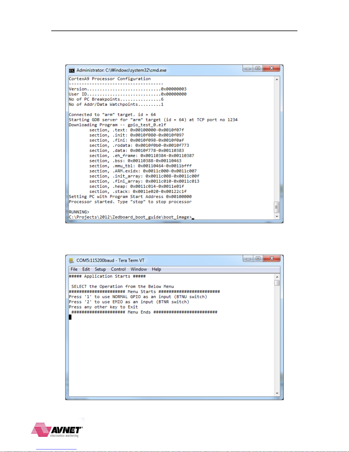
5. The FPGA bitstream will be downloaded, followed by the executable file for the
software application. Do not close the command window.
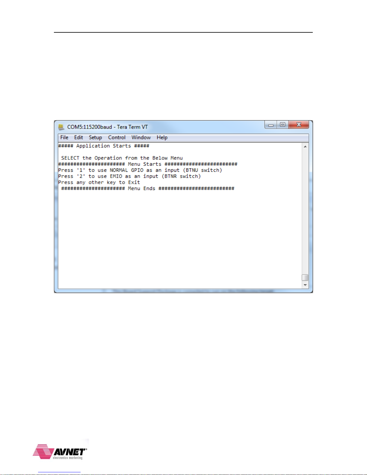
6. When the executable has finished loading and is ready to run you should see the
following in your serial terminal window:
8
Page 10
ZedBoard Booting and Configuration Gui de ISE Design Suite 14.1
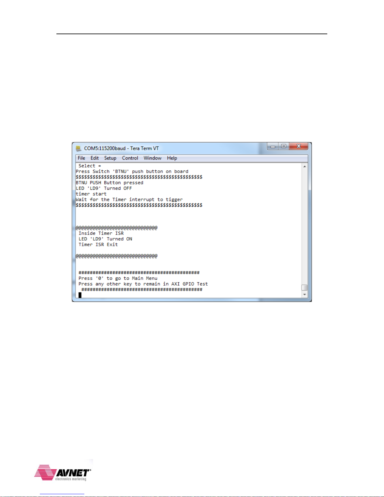
GPIO Test Demo
The GPIO Test application running on the ZedBoard takes user input to select which
push-button switch is used to trigger the timer to turn the LED on and off.
1. Follow the screen prompts to select the push button input. One push button is routed
to the AXI GPIO peripheral (BTNU) and the other is routed to the CPU GPIO
(BTNR) through the EMIO interface between the PS and PL sections. Run the
application as many times as you wish and alternate which push button is selected.
Leave the terminal window open when you are done. We will reuse this terminal
session again later.
9
Page 11
ZedBoard Booting and Configuration Gui de ISE Design Suite 14.1
SDK Software Tasks
This aspect of the design is performed inside a SDK workspace. As you may know, the
Xilinx SDK is the Integrated Design Environment (IDE) where all software related tasks
are performed for both Linux and standalone (bare metal) software application
development. Here we will import the pre-built GPIO test software application that is
described in the ZedBoard CTT guide and create the Zynq First Stage Boot Loader
(FSBL) that we will copy to the SD card and boot on the ZedBoard.
Create the SDK Workspace
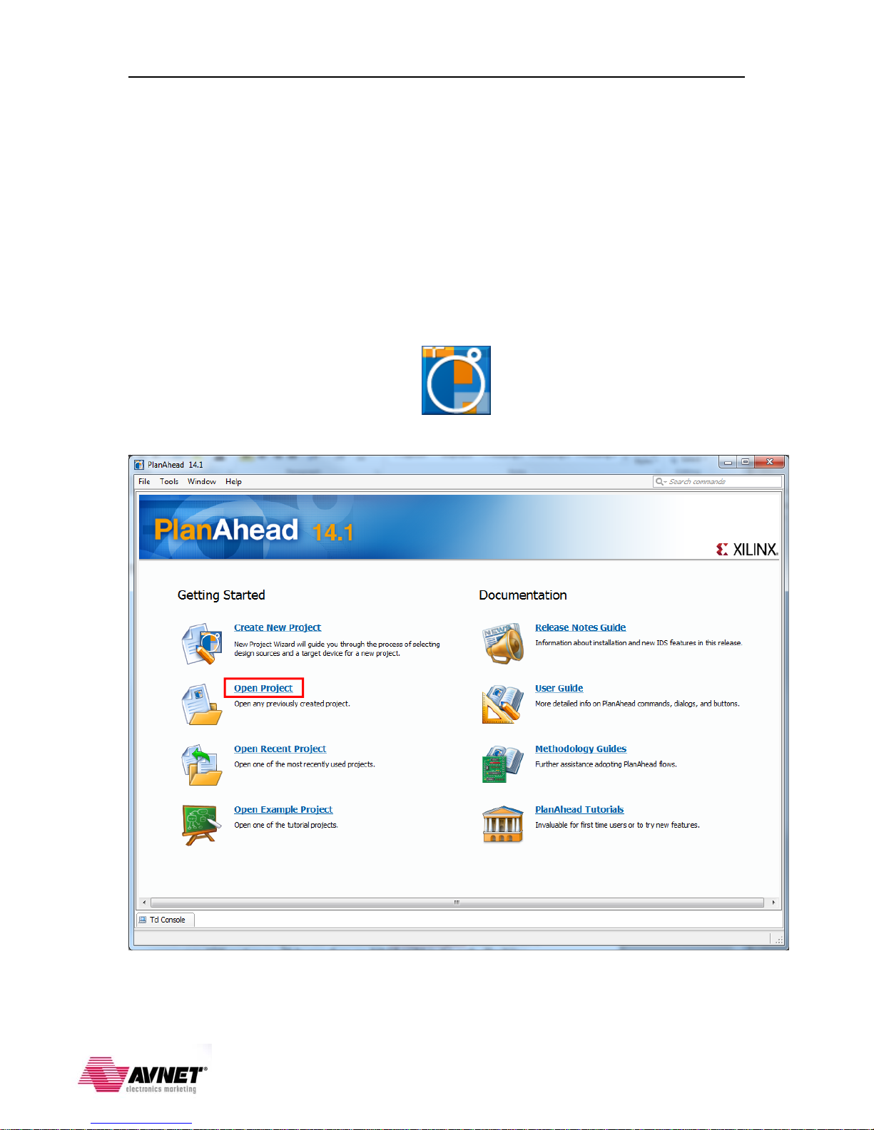
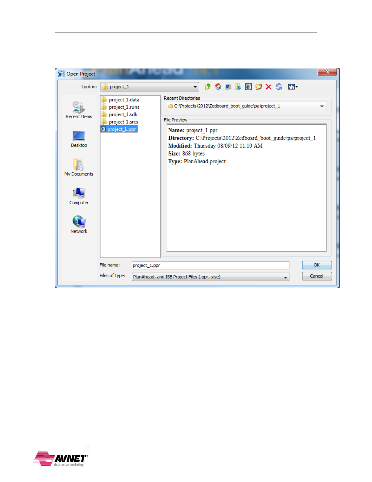
1. Start in PlanAhead to generate an empty SDK workspace based on the pre-built
hardware platform described in the ZedBoard CTT guide. Navigate the Windows™
Start Menu or double click on the icon on your desktop to open PlanAhead
and select Open Project.
10
Page 12
ZedBoard Booting and Configuration Gui de ISE Design Suite 14.1
2. Navigate to the <installation>\pa\project_1 folder and select the project_1.ppr
project file. Click OK to continue.
11
Page 13

ZedBoard Booting and Configuration Gui de ISE Design Suite 14.1
3. The project will open and display the Flow Navigator and Project Manager view
with the Project Summary. Select File Export Export Hardware… from the
PlanAhead GUI.
4. Accept the defaults and check the box to Launch SDK. Click OK to continue.
PlanAhead will display the following window while the SDK workspace is created:
12
Page 14
ZedBoard Booting and Configuration Gui de ISE Design Suite 14.1
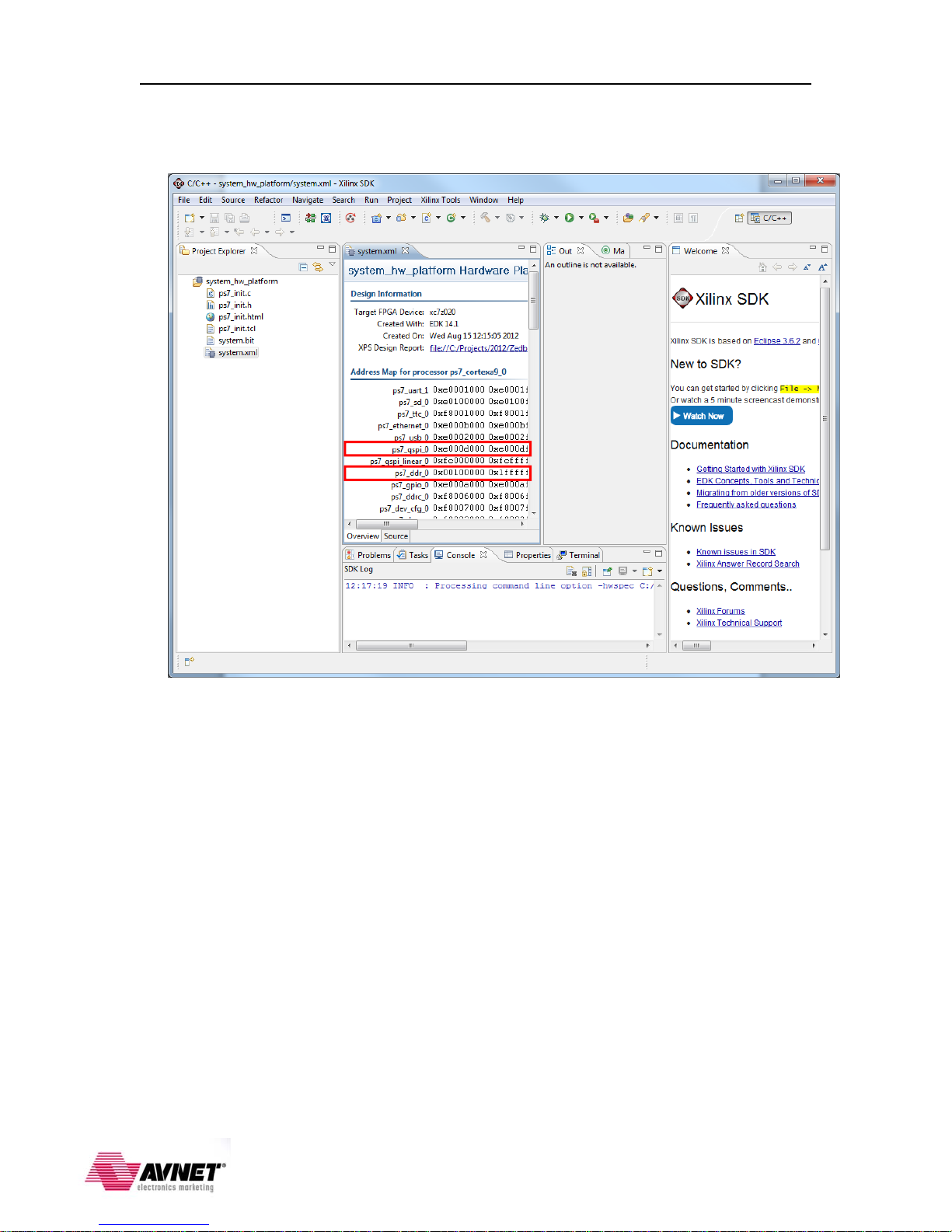
5. The SDK will open with a new empty workspace with just the imported
system_hardware_platform similar to the window shown below.
6. Make note of the base address for the DDR3 SDRAM (ps7_ddr_0 - 0x00100000)
and the QSPI Flash (ps7_qspi_0 - 0xE000D000). We will need to know this when
we program the QSPI Flash later when we prepare to boot the ZedBoard in QSPI boot
mode.
13
Page 15

ZedBoard Booting and Configuration Gui de ISE Design Suite 14.1
Create the Board Support Package
The first thing we need to create in our empty workspace is a Board Support Package
(BSP) on which individual projects can be built. Multiple BSPs and multiple application
projects can be held in a single SDK workspace. To begin, create a basic BSP that is
adequate for the GPIO test and FSBL applications we intend to run.
1. From the SDK main menu, select File New Xilinx Board Support Package.
2. Accept the defaults for the Project name, Hardware Platform, CPU, and OS.
Click Finish to continue.
14
Page 16

ZedBoard Booting and Configuration Gui de ISE Design Suite 14.1
3. At this point the basic software platform to build general applications for this board
has been created. We do not need to add additional software libraries to the BSP or
change any settings, so click OK to continue and the software platform will
automatically compile link.
15
Page 17
ZedBoard Booting and Configuration Gui de ISE Design Suite 14.1
Import the GPIO Test Software Application
The GPIO test application is described in the Appendix A of the ZedBoard CTT and is
pre-built for us to use here. Feel free to examine and become familiar with the source
code for this application. The next step is to import this application so we can build and
run it on the board.
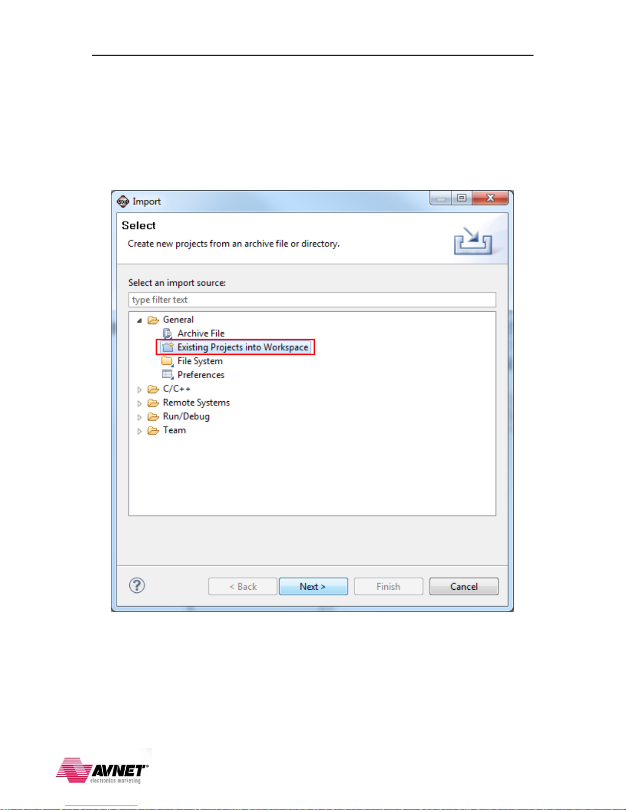
1. Go to File Import General Existing Projects into Workspace
16
Page 18
ZedBoard Booting and Configuration Gui de ISE Design Suite 14.1
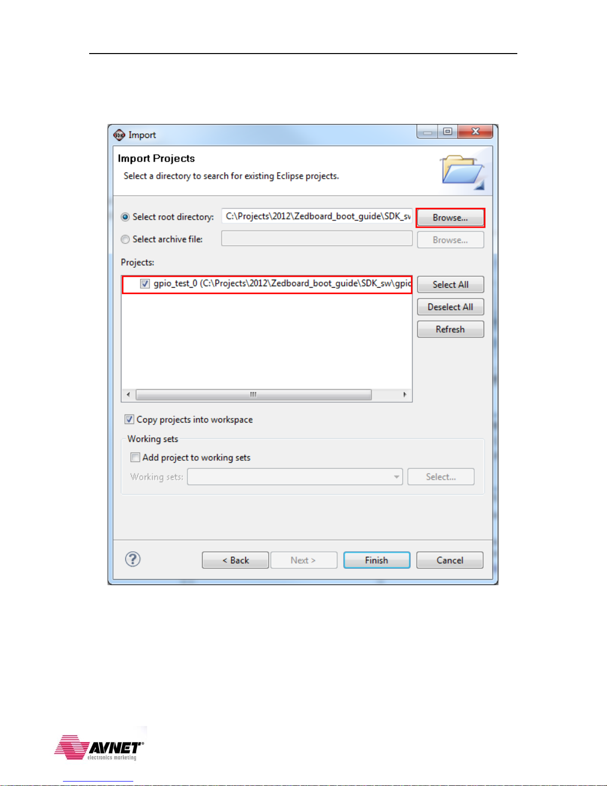
2. Click Browse… and navigate to the <installation>\SDK_sw\gpio_test_0 folder.
Check the box to Copy projects into workspace and click Finish to continue. The
software application will automatically build and be added to the SDK workspace.
At this point the gpio_test_0 application is ready to run, but first we must setup the Xilinx
Microprocessor Debugger (XMD) options to download and run the software application.
17
Page 19

ZedBoard Booting and Configuration Gui de ISE Design Suite 14.1
Running the GPIO Test Software Application
1. Turn off the ZedBoard if it is turned on. Verify the Configuration Mode jumpers are
set for JTAG mode (all pins shunted to GND) as in the figure below:
2. Slide the power switch (SW8) to the ON position. You will see the green ‘power
good’ LED (LD13) illuminate.
3. To prepare for running the gpio_test_0 software application later we will configure
the Zynq device with the PL bitstream that includes the AXI timer and GPIO
peripherals. In the SDK main menu, select Xilinx Tools Program FPGA or click
on the on the SDK toolbar:
18
Page 20

ZedBoard Booting and Configuration Gui de ISE Design Suite 14.1
4. Since this is a Zynq hardware platform there is no BMM file or ELF file to initialize
in Block RAM, so accept the default for the system.bit file for the PL bitstream that
was exported from the PlanAhead hardware project earlier. Click Program to
continue:
You will see the following window while the PL bitstream is downloaded. Once this is
complete the blue ‘DONE’ LED (LD12) will illuminate.
19
Page 21

ZedBoard Booting and Configuration Gui de ISE Design Suite 14.1
5. In the Project Explorer window pane select the gpio_test_0 application and right-
click to select Run As Run Configurations…
20
Page 22

ZedBoard Booting and Configuration Gui de ISE Design Suite 14.1
6. Click on the option in the left panel and press the New to
create a new Debug run configuration for the gpio_test_0 software application.
7. Select the new gpio_test_0 Debug run configuration. Click Run continue.
21
Page 23

ZedBoard Booting and Configuration Gui de ISE Design Suite 14.1
8. You will see the following window warning you that both CPU cores will be reset.
Since this system only uses one of the CPU cores it doesn’t matter that both will be
reset and we can ignore this warning. Click OK to continue.
9. You should see the following on the serial console:
10. You are now ready to run the GPIO test software application. The steps to run the
application are the same as running the demo you probably used earlier, except the
steps of downloading the PL bitstream and application executable are already
completed. Leave the terminal window open when you are done. We will reuse this
terminal session again later.
22
Page 24
ZedBoard Booting and Configuration Gui de ISE Design Suite 14.1
Create the First Stage Boot Loader
To prepare for booting the gpio_test_0 software application at power-up later we will
need to create the first stage boot loader application. This application is one of the
example software applications built into the SDK.
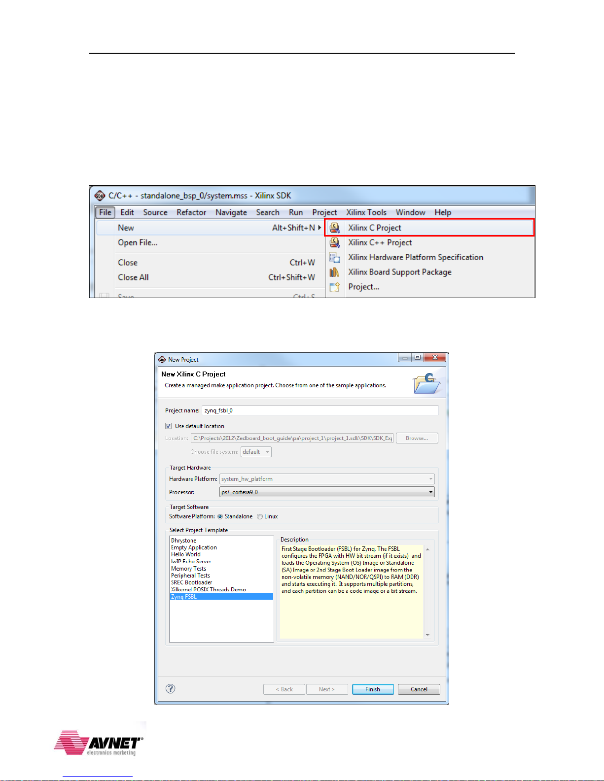
1. Go to File New Xilinx C Project to open the window to select from the
available example software applications.
2. Select the Zynq FSBL project template. Accept the defaults for the Project Name
and Target Hardware Platform. Click Finish to continue:
23
Page 25
ZedBoard Booting and Configuration Gui de ISE Design Suite 14.1
Create the Boot Image
To boot the GPIO test application and configure the PL with the hardware bitstream at
power on we first need to create the boot image to be copied to our boot media. The boot
image is actually the GPIO test and FSBL application executable files and PL bitstream
packaged into a single BOOT.BIN file. The Zynq boot ROM will look for this file on the
boot media. It must be named BOOT.BIN in upper-case letters.
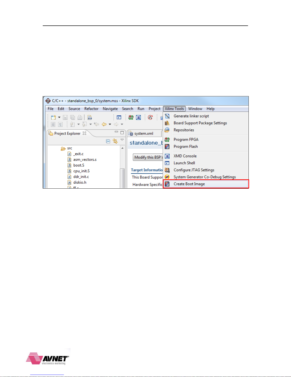
1. Go to Xilinx Tools Create Boot Image.
24
Page 26

ZedBoard Booting and Configuration Gui de ISE Design Suite 14.1
2. There are a few tasks we need to do while in this window. The PL bitstream and
GPIO test application elf file are added in the order they are needed during boot.
Since the PL needs to be configured before the PS runs the application executable the
PL bitstream is added first:
a. Accept the Bif file default Create a new bif file… The Bif file is a text file that
describes the contents of the boot image. This file can subsequently be used to
recreate or modify the BOOT.BIN boot image file
b. To specify the FSBL elf file click on Browse and navigate to
<installation>\pa\project_1\project_1.sdk\SDK\SDK_Export\zynq_fsbl_0\Debug
and select the zynq_fsbl_0.elf file.
c. To add the PL bitstream click on Add and navigate to
<installation>\pa\project_1\project_1.sdk\SDK\SDK_Export\system_hw_platform
and select the system.bit file.
d. To add the GPIO test software application executable click on Add again and navigate to
<installation>\pa\project_1\project_1.sdk\SDK\SDK_Export\gpio_test_0\Debug and
select the gpio_test_0.elf file.
e. To specify the Output file click on Browse and navigate to
<installation>\boot_image and name the file BOOT.BIN.
f. Click Create Image to continue:
25
Page 27

ZedBoard Booting and Configuration Gui de ISE Design Suite 14.1
Booting From the SD Card
With the SDK tasks completed, we are now ready to boot our system from the SD card.
Prepare the SD Card
1. Take the SD card that came with the ZedBoard and install it in an open SD card slot
on your PC host. Using Windows Explorer identify the drive letter where the SD
card is mounted and backup the SD card contents to a folder of your choice on your
PC host. Once the SD card files are backed up on the PC, delete them from the SD
card.
2. In Windows Explorer navigate to <installation>\boot_image and copy the BOOT.BIN
file to the SD card.
3. Turn off the ZedBoard if it is turned on. Verify the Configuration Mode jumpers are
set for SD card mode as described and in the figure below:
MODE3 (JP10) shunted to 3.3V
MODE2 (JP9) shunted to 3.3V
All other MODE pins shunted to GND
4. Remove the SD card from the PC and insert it in the SD card slot of the ZedBoard.
5. Slide the power switch (SW8) to the ON position. You will see the green ‘power
good’ LED (LD13) will illuminate immediately and the blue ‘DONE’ LED (LD12)
will illuminate once the processor has been initialized and then configures the PL.
When booting from SD card this may take 10-15 seconds.
26
Page 28
ZedBoard Booting and Configuration Gui de ISE Design Suite 14.1
GPIO Test Demo
1. At power on the Zynq boot ROM samples the boot mode strapping pins and
determines the boot method. Once the boot method is determined the boot ROM will
search the boot media for the BOOT.BIN file and attempt to execute the First Stage
Boot Loader (FSBL). The FSBL will then configure the PL if a bitstream is found
and hand over system execution to the application executable. When booting from
SD card this process may take 10-15 seconds. You should see the following on the
serial console when the system has completed booting:
2. You are now ready to run the GPIO test software application. The steps to run the
application are the same as running the demo you probably used earlier, except the
system has now booted from the SD card and the steps of configuring the PL with the
hardware bitstream and starting the application executable happened automatically at
power on. Leave the terminal window open when you are done. We will reuse this
terminal session again later.
27
Page 29

ZedBoard Booting and Configuration Gui de ISE Design Suite 14.1
Booting From QSPI Flash
To boot from QSPI flash the BOOT.BIN file must first be programmed to the base
address of the QSPI flash. Normally this could be done using the SDK, but that function
is not working with the current SDK tools. Instead we will use the flash programming
capabilities of the popular u-boot bootloader. As we did previously when booting the
ZedBoard in JTAG mode, we will use command line XMD scripts to initialize the CPU
and download the u-boot application to the board for execution.
Program the QSPI Flash
1. Verify the ZedBoard is powered off and that the configuration Mode jumpers are set
for JTAG mode (all pins shunted to GND) as in the figure below:
2. Verify the SD card is installed in the ZedBoard. We will be copying the BOOT.BIN
file on the SD card into DDR3 memory and then to QSPI Flash.
3. Slide the power switch (SW8) to the ON position. You will see the green ‘power
good’ LED (LD13) illuminate.
4. Open a command window in the <installation>\demo folder and enter:
run_uboot.bat
This batch file sets the proper environment variables and creates the xmd.ini script of
commands to be used by the Xilinx Microprocessor Debugger (XMD) tool to
initialize the processor, download the u-boot software application, and begin
execution on the system by performing the following commands automatically:
connect arm hw
source ps7_init.tcl
ps7_init
dow u-boot_autoboot_disabled.elf
run
exit
28
Page 30

ZedBoard Booting and Configuration Gui de ISE Design Suite 14.1
5. The processor will be initialized and the u-boot application will be downloaded for
the execution. Do not close the command window.
6. When the u-boot executable has finished loading and is ready to run you should see
the following in your serial terminal window:
29
Page 31

ZedBoard Booting and Configuration Gui de ISE Design Suite 14.1
7. Enter the following commands in the serial terminal window to initialize the SD card
and QSPI flash:
mmcinfo
sf probe 0 0 0
30
Page 32

ZedBoard Booting and Configuration Gui de ISE Design Suite 14.1
8. Prior to copying the BOOT.BIN file from the SD card to DDR3 memory we need to
first write a block of 0xFF to the area of DDR3 that we will use to temporarily store
the BOOT.BIN file. We do this so that when we copy the BOOT.BIN from DDR3 to
QSPI Flash, the data we copy beyond the end of the BOOT.BIN file will look like
empty memory space to subsequent use of the QSPI Flash. Strictly speaking this is
not necessary, but would be a help later if we needed to maximize use of the QSPI
flash for other purposes. The size of the boot image (BOOT.BIN) is 0x40D930
bytes, so we will prepare an area slightly larger. Recall earlier when we created the
SDK workspace that we made note of the system base address for the DDR3 SDRAM
(ps7_ddr_0 - 0x00100000). We need that information now. Use the u-boot
memory write command:
mw.b 0x00200000 0xFF 0x410000
The format of this command is:
mw.b <RAM address> <fill value> <length>
NOTE: The <RAM address> must be at an offset above the base address where the
u-boot application is running.
31
Page 33

ZedBoard Booting and Configuration Gui de ISE Design Suite 14.1
9. This step will copy the BOOT.BIN file from the SD card to DDR3 memory. Recall
earlier when we created the SDK workspace that we made note of the QSPI Flash
(ps7_qspi_0 - 0xE000D000). We need that information now. Copy the boot image
from the SD card into RAM:
fatload mmc 0 0x00200000 BOOT.BIN
The format of this command is
fatload <interface> <device> <RAM address> <filename>
32
Page 34

ZedBoard Booting and Configuration Gui de ISE Design Suite 14.1
10. Prepare the QSPI Flash. We must erase the area of flash first. The size of the boot
image (BOOT.BIN) is 0x40D930 bytes, so we will prepare an area slightly larger:
sf erase 0 0x410000
The format of this command is:
sf erase <offset> <length>
33
Page 35

ZedBoard Booting and Configuration Gui de ISE Design Suite 14.1
11. Store the boot image to the QSPI Flash:
sf write 0x00200000 0 0x410000
The format of this command is:
sf write <source address> <offset> <length>
34
Page 36

ZedBoard Booting and Configuration Gui de ISE Design Suite 14.1
12. Turn off the ZedBoard. Verify the Configuration Mode jumpers are set for QSPI
boot mode as described and in the figure below:
MODE3 (JP10) shunted to 3.3V
All other MODE pins shunted to GND
13. Slide the power switch (SW8) to the ON position. You will see the green ‘power
good’ LED (LD13) will illuminate immediately and the blue ‘DONE’ LED
(LD12) will illuminate once the processor has been initialized and then configures
the PL. When booting from QSPI Flash this may take a couple of seconds.
35
Page 37

ZedBoard Booting and Configuration Gui de ISE Design Suite 14.1
GPIO Test Demo
1. At power on the Zynq boot ROM samples the boot mode strapping pins and
determines the boot method. Once the boot method is determined the boot ROM will
search the boot media for the BOOT.BIN file and attempt to execute the First Stage
Boot Loader (FSBL). The FSBL will then configure the PL if a bitstream is found
and hand over system execution to the application executable. When booting from
QSPI Flash this process happens very quickly. So quickly, in fact, that the GPIO test
application starts executing before the USB UART driver has a chance to load on the
host PC. This causes the serial terminal window to display a partial GUI or no GUI at
all. Based on our previous use of this application throughout this boot guide, though,
we know what keys to press to start using the application so proper display of the
GUI will resume. To start, press '1' to use NORMAL GPIO as an input (BTNU
switch):
2. You are now ready to run the GPIO test software application. The steps to run the
application are the same as running the demo you probably used earlier, except the
system has now booted from the QSPI Flash and the steps of configuring the PL with
the hardware bitstream and starting the application executable happened
automatically at power on. Close the terminal and command windows when you are
done. This concludes this design tutorial.
36
Page 38

ZedBoard Booting and Configuration Gui de ISE Design Suite 14.1
Where to Get More Information
ZedBoard Website
Documentation, Tutorials, and Reference Designs
www.zedboard.org
ZedBoard Hardware User’s Guide
www.zedboard.org/sites/default/files/ZedBoard_HW_UG_v1_3.pdf
Cypress USB-to-UART Setup Guide
www.zedboard.org/sites/default/files/CY7C64225_Setup_Guide_1_1.pdf
Concepts, Tools and Techniques Guide
www.zedboard.org/design
Xilinx Website
All Zynq Documentation
www.xilinx.com/support/documentation/zynq-7000.htm
Zynq-7000 AP SoC Software Developers Guide
www.xilinx.com/support/documentation/user_guides/ug821-zynq-7000-swdev.pdf
Revision History
Version Date Author Details
1.0 August 16, 2012 TC Initial release. ISE 14.1
1.1 August 17, 2012 TC Review notes from group review
37
 Loading...