

Page 1
Copyright © 2018 Avnet, Inc. AVNET, “Reach Further” and Avnet logo are registered
trademarks of Avnet, Inc. All other brands are the property of their respective owners.
LIT#
Telus LTE-M IoT Starter Kit
Hardware User Guide
Version 3.2
Page 2

Page 2
Version
Date
Comment
1.0
07/06/2018
Initial Release
2.0
09/10/2018
Updated photos (to show production version BG96 modem board)
3.0
10/23/2018
Updated photos and description of v2 starter kit
MCU board details changed to that of NUCLEO-L496
Added P/N, product page and purchase page URLs (3.1)
Contact Info and Technical Support info updated (16, 17)
3.1
10/24/2018
Added detail of SW2, SW3 settings for NUCLEO-L496 MCU board
3.2
10/25/2018
Corrected Figure 3 label for SIM card holder
Document Control
Document Version: 3.2
Document Date: 10/25/2018
Document Author(s): Peter Fenn
Document Classification: Public
Document Distribution: Public
Prior Version History
Page 3

Page 3
Contents
1 Introduction ........................................................................................................... 5
1.1 BG96 Module Features ............................................................................................................ 5
2 System-Level Block Diagram ................................................................................ 6
3 Telus LTE-M IoT Starter Kit .................................................................................. 7
3.1 Telus LTE-M IoT Starter Kit (v2) Info ....................................................................................... 7
3.2 Items Included in the Starter Kit ............................................................................................... 7
4 Configuration Switches ......................................................................................... 9
4.1 SW1: Selection of Input Voltage Source ................................................................................ 10
4.2 SW2, SW3: Selection of UART0 Connection to Arduino Pins ............................................... 10
5 Status LEDs ........................................................................................................ 11
5.1 LED1: Network Status ............................................................................................................ 11
5.2 LED2: VBAT_3V8 Status ....................................................................................................... 11
5.3 LED3: BG96 Status ................................................................................................................ 11
6 PWRKEY Pushbutton Switch (S1) ...................................................................... 12
7 SIM / eSIM Interface ........................................................................................... 12
8 BG96 Shield - Arduino Connectors ..................................................................... 13
9 Pmod Connector ................................................................................................. 14
10 LTE Antenna ....................................................................................................... 15
11 GPS Antenna ...................................................................................................... 15
12 The Telus LTE-M IoT Starter Kit ......................................................................... 16
12.1 Assemble the Board Stack ..................................................................................................... 16
12.2 Connect the LTE and GPS Antennas ..................................................................................... 16
12.3 Connect the USB Cable ......................................................................................................... 16
13 Sensor Board (X-NUCLEO-IKS01A2) ................................................................. 17
14 MCU Board (NUCLEO-L496ZG) ......................................................................... 18
15 MCU Board Arduino Connectors (NUCLEO-L496ZG) ........................................ 19
16 Contact Info and Technical Support .................................................................... 22
17 Disclaimer ........................................................................................................... 22
Appendix-A: Standalone LTE-M Modem Test (Optional) .......................................... 23
Appendix-B: Standalone GPS Test (Optional) .......................................................... 25
Page 4

Page 4
Figures
Figure 1 – System-Level Block Diagram ................................ ..................................... 6
Figure 2 – Location of Key Components on the BG96 Shield ..................................... 8
Figure 3 – Location of Slider Switches ........................................................................ 9
Figure 4 – SW2, SW3 Settings for NUCLEO-L496 ..................................................... 9
Figure 5 – SW2, SW3 Selection of UART0 Arduino Pins .......................................... 10
Figure 6 – SIM Card Orientation and eSIM Selector Switch ...................................... 12
Figure 7 – Pinout of BG96 Shield Arduino Connectors ............................................. 13
Figure 8 – Pmod Connector Pin View from Board Edge ........................................... 14
Figure 9 – LTE Wideband Flex Antenna (FXUB63) .................................................. 15
Figure 10 – GPS Flex Antenna (FXP611) ................................ ................................ . 15
Figure 11 – Board Stack-Up Detail ............................................................................ 16
Figure 12 – X-NUCLEO-IKS01A2 Sensor Board ...................................................... 17
Figure 13 – NUCLEO-L496ZG MCU Board .............................................................. 18
Figure 14 – Nucleo-L496ZG Arduino Connectors ..................................................... 19
Figure 15 – Nucleo-L496ZG Arduino Pinouts (Left-Side) .......................................... 20
Figure 16 – Nucleo-L496ZG Arduino Pinouts (Right-Side)........................................ 21
Figure 17 – BG96 COM ports Reported in Device Manager ..................................... 23
Tables
Table 1 – BG96 Shield Configuration Switches ........................................................... 9
Table 2 – BG96 Shield LEDs .................................................................................... 11
Table 3 – BG96 Shield Network Status LED1 ........................................................... 11
Table 4 – BG96 Shield Pmod Connector Pinout ....................................................... 14
Table 5 – Nucleo-L496ZG User LEDs and User Button ............................................ 20
Page 5

Page 5
1 Introduction
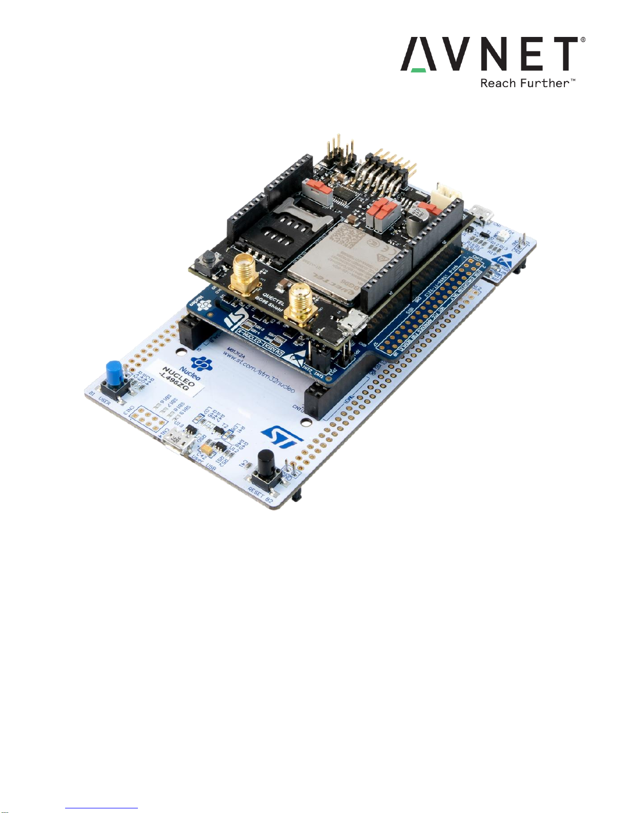
The Telus LTE-M IoT Starter Kit integrates three boards (stacked via their Arduino connectors):
Avnet Quectel BG96 Shield (LTE Cat-M1 and NB-IoT cellular modem and GPS board)
STMicro NUCLEO-L496ZG MCU Board
STMicro X-NUCLEO-IKS01A2 Sensor Board
Enabled with the new Telus LTE-M IoT service plus free online development tools, product developers are
equipped with a versatile, rapid prototyping platform, for defining innovative new custom IoT products
The low-power Quectel BG96 IoT wireless module on this board is configured and operated via an
extensive set of AT commands. Mbed OS5 software examples are provided, enabling rapid application
development, using Mbed online IDE, libraries and software stacks (SSL, MQTT, COAP etc.)
The 2nd use-case of the BG96 Shield is a Pmod-connected modem peripheral, for host boards that support
a Pmod-compatible interface.
The 3rd use-case of the BG96 Shield is a USB-connected modem, supporting three serial ports (via USB):
UART1 - data transmission and AT command communication
UART2 - module debugging and log output
UART3 - output of GPS data / NMEA sentences
The power supplied to this board may be:
5V DC sourced from USB connector or Arduino shield connector, or
3.3V DC sourced from Pmod connector
VBAT from the battery connector
The provided wide-band LTE flex antenna, delivers good signal strength across multiple LTE frequency
bands. A passive GPS flex antenna is also provided
1.1 BG96 Module Features
Based on Quectel BG96 LPWA module
Multiple operating modes: Cat-M1, Cat-NB1, EGPRS
Global LTE bands support
o Cat-M1/NB1: B1 B2 B3 B4 B5 B8 B12 B13 B18 B19 B20 B26 B28 B39 (B39 for M1 only)
o EGPRS: 850/900/1800/1900 MHz
Low Power Consumption
o Approximately 10 uA in PSM mode
GNSS (GPS, GLONASS, BeiDou/Compass, Galileo, QZSS)
VoLTE Voice over LTE support (M1 only. Not pinned-out on the BG96 Shield!)
PCM digital audio interface (Not pinned-out on the BG96 Shield!)
Connectors
o SIM Card holder
o Arduino Shield interface
o Pmod interface
Software
o Modem and GPS support via AT Commands
o Built in support for PPP/TCP/UDP/SSL/TLS/FTP(S)/HTTP(S)
o Support for major operating systems (Android, Linux, Windows)
o Support for Mbed OS5 for integrated embedded development
Page 6
Page 6
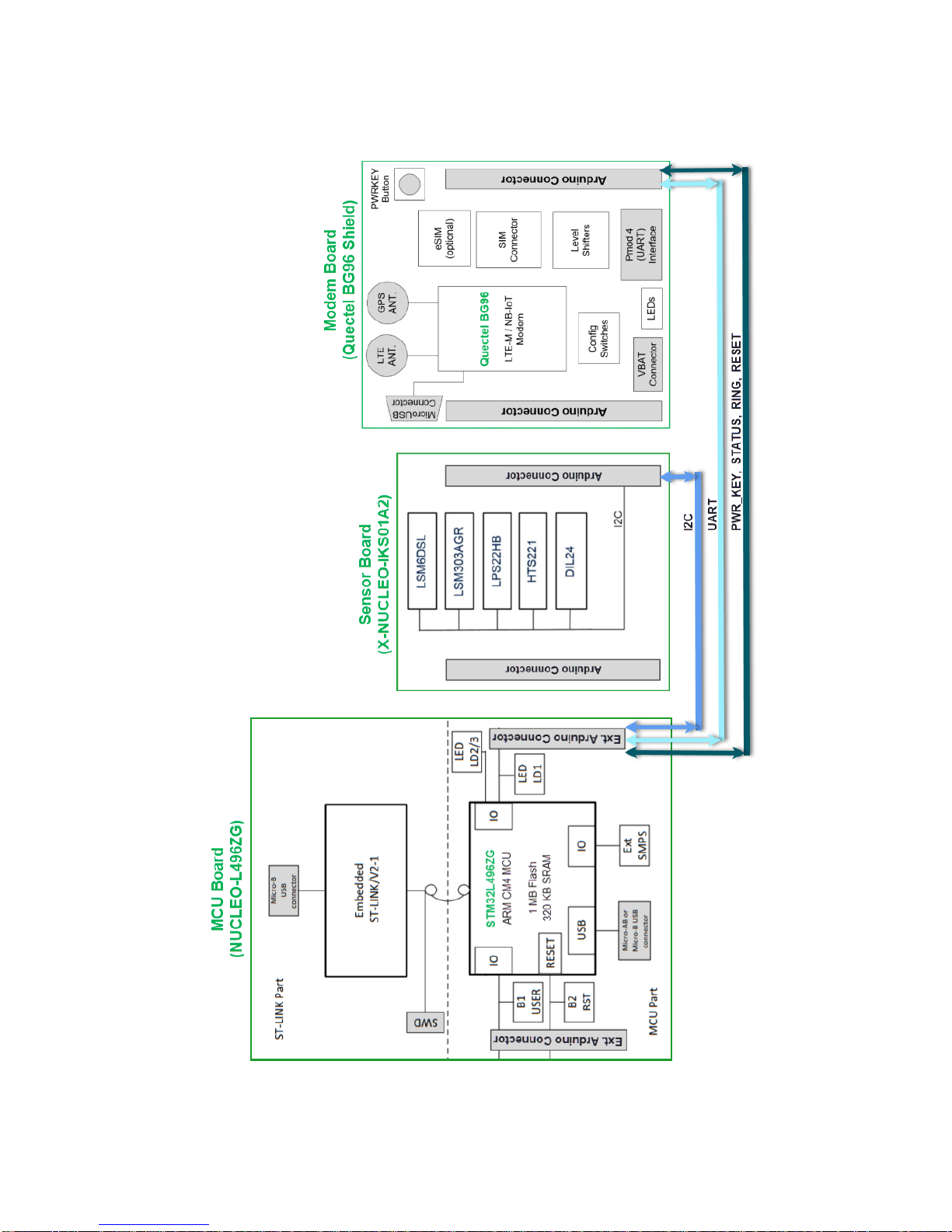
2 System-Level Block Diagram
Figure 1 – System-Level Block Diagram
Page 7
Page 7
3 Telus LTE-M IoT Starter Kit
3.1 Telus LTE-M IoT Starter Kit (v2) Info
Part Number: AES-BG96-IOT-SK2-G
Kit URL: http://cloudconnectkits.org/product/telus-iot-starter-kit
Buy Page: http://avnet.me/telus1-iot
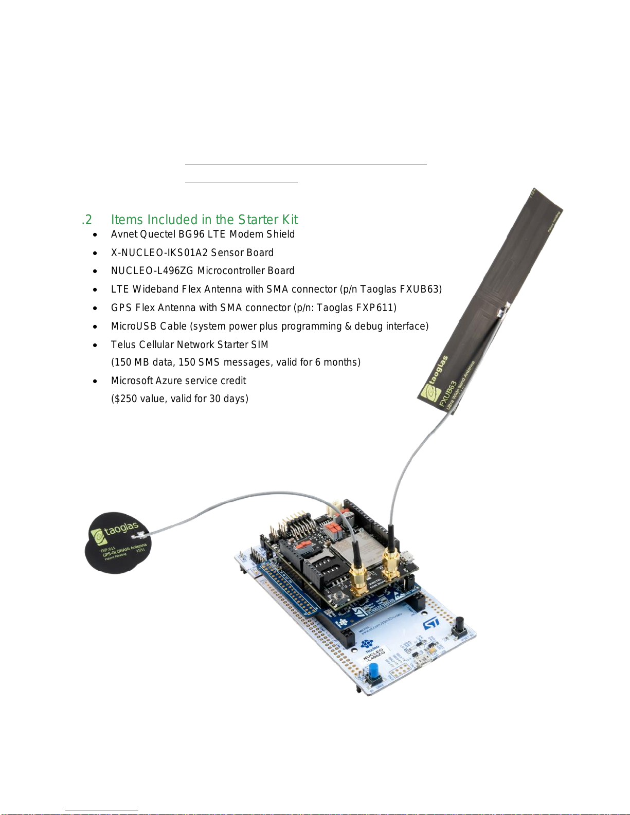
3.2 Items Included in the Starter Kit
Avnet Quectel BG96 LTE Modem Shield
X-NUCLEO-IKS01A2 Sensor Board
NUCLEO-L496ZG Microcontroller Board
LTE Wideband Flex Antenna with SMA connector (p/n Taoglas FXUB63)
GPS Flex Antenna with SMA connector (p/n: Taoglas FXP611)
MicroUSB Cable (system power plus programming & debug interface)
Telus Cellular Network Starter SIM
(150 MB data, 150 SMS messages, valid for 6 months)
Microsoft Azure service credit
($250 value, valid for 30 days)
Page 8
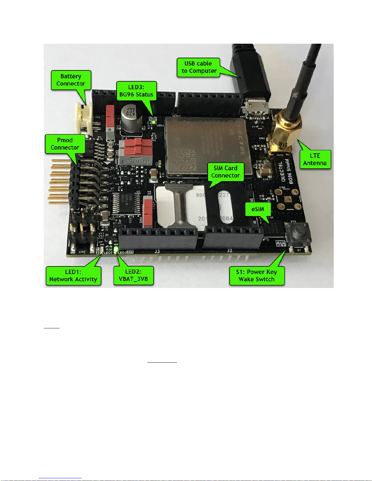
Page 8
Figure 2 – Location of Key Components on the BG96 Shield
Notes:
The provided USB cable should be connected to the ST-Link/UART interface of the MCU board.
The only time this USB cable can be connected to the BG96 board (as shown in above photo) is
when the BG96 board is used standalone for eg. the following use cases:
a) Standalone BG96 modem or GPS testing (as detailed in Appendix A and B)
b) In the event of needing to upgrade the Quectel firmware on the modem module
Page 9

Page 9
4 Configuration Switches
#
Red Slider
Pos. 1-2
Red Slider
Pos. 2-3
Description of the
Function Controlled
SW1
Pmod
Onboard V_Reg.
Source of VBAT_3V8 power (from the onboard
Voltage Regulator, or the Pmod Connector)
SW2
Nucleo-L476 RX
(pin D2)
Nucleo-L496 RX
(pin D0)
BG96 UART0 TXD destination
SW3
Nucleo-L476 TX
(pin D8)
Nucleo-L496 TX
(pin D1)
BG96 UART0 RXD source
SW4
SIM card
eSIM
Connect USIM data I/O to eSIM or SIM
The slide switches (Wurth WS-SLTV series) on the BG96 board have "opposite-side connection"!
ie. When red slider is positioned across pins 1-2, the circuit of pins 2-3 is bridged !!!
The highlighted switch settings in the table below, match the red slider positions
Table 1 – BG96 Shield Configuration Switches
Figure 3 – Location of Slider Switches
Figure 4 – SW2, SW3 Settings for NUCLEO-L496
Page 10

Page 10
4.1 SW1: Selection of Input Voltage Source
#
Red Slider
Pos. 1-2
Red Slider
Pos. 2-3
Description of the
Function Controlled
SW2
Nucleo-L476 RX
(pin D2)
Nucleo-L496 RX
(pin D0)
BG96 UART0 TXD destination
SW3
Nucleo-L476 TX
(pin D8)
Nucleo-L496 TX
(pin D1)
BG96 UART0 RXD source
Slider switch SW1 determines if the supply voltage to the BG96 module is from:
a) the onboard 3.8V voltage regulator (which is supplied from 5V pin on Arduino connector), or
b) the Pmod 3.3V pins or external battery connector
For use in this Starter Kit, the output of the onboard regulator should be used
4.2 SW2, SW3: Selection of UART0 Connection to Arduino Pins
Note that for use with a NUCLEO-L496ZG microcontroller board, UART0 of the BG96 must be routed
to the pins that match the D2 and D8 pins of the Arduino Shield interface standard
Figure 5 – SW2, SW3 Selection of UART0 Arduino Pins
Page 11

Page 11
5 Status LEDs
Ref Des
Signal Name
Function
LED Color
(New PCB)
LED1
NETLIGHT
Network Activity
Blue
LED2
VBAT_3V8
Power Regulator Status
Green
LED3
BG96_STATUS
BG96 Power Status
Green
Ref Des
LED Indication
Network Status
LED1
(NETLIGHT)
Short ON, Long OFF (0.2s / 1.8s)
Network Searching
Long ON, Short OFF (1.8s / 0.2s)
Idle
Periodic ON, OFF (0.125s / 0.125s)
Data transfer is ongoing
Continuously ON
Voice calling (Note: VoLTE
is not supported by this
BG96 Shield!)
The BG96 Shield is equipped with three status LEDs. Interpretation of these LEDs is tabled below:
Table 2 – BG96 Shield LEDs
5.1 LED1: Network Status
Table 3 – BG96 Shield Network Status LED1
5.2 LED2: VBAT_3V8 Status
Should remain ON constantly
5.3 LED3: BG96 PWR Status
Note that the status indicated by this LED is inverted!
LED3 = ON when BG96 module is in Power Down mode
LED3 = OFF when BG96 module is active
The state of the BG96 module and this BG96 PWR status LED can be changed
by the host MCU, or by the User doing one of the following:
pressing PWRKEY button switch S1
entering an AT+QPOWD command
Page 12

Page 12
6 PWRKEY Pushbutton Switch (S1)
The PWRKEY button switch provides two functions to the User. It can be used to:
Wake-Up or Power-Down the BG96 module
Manually exit the BG96 module’s Power Saving Mode (PSM)
7 SIM / eSIM Interface
The BG96 Shield is fitted with a preconfigured Infineon eSIM device. If you want to use a removable SIM
card, then SW4 must be set accordingly and the SIM should be activated on the carrier’s website
To insert a SIM card, slide the metal retaining clip in direction of the PWR KEY Push-button switch, then lift
this up and inserting the SIM with notched corner facing outwards as shown below. Lock the SIM into place
by pressing on the SIM holder and sliding the metal retaining clip back in the other direction.
Figure 6 – SIM Card Orientation and eSIM Selector Switch
Page 13

Page 13
8 BG96 Shield - Arduino Connectors
Figure 7 – Pinout of BG96 Shield Arduino Connectors
Page 14

Page 14
9 Pmod Connector
Pmod
Pin#
Signal Name
Pmod
Pin#
Signal Name
1
UART0_RING_3V3
7
BG96_STATUS
2
UART0_RXD_3V3
8
RESET_PMOD
3
UART0_TXD_3V3
9
4
BG96_PWRKEY_ACTIVE HIGH
10 5
GND
11
GND
6
3V3
12
3V3
The BG96 Shield may alternatively be utilized as a Pmod-connected modem peripheral, for host boards that
support a Pmod-compatible interface (BG96 Shield has a right-angle, male 2x6 Pmod connector)
Table 4 – BG96 Shield Pmod Connector Pinout
Figure 8 – Pmod Connector Pin View from Board Edge
Page 15

Page 15
10 LTE Antenna
Taoglas LTE Wideband Flex Antenna (FXUB63)
(fitted with an SMA-male connector) is included in the LTE-M IoT Starter Kit
Figure 9 – LTE Wideband Flex Antenna (FXUB63)
11 GPS Antenna
Taoglas GPS Flex Antenna (FXP611)
(fitted with an SMA-male connector) is included in the LTE-M IoT Starter Kit
Use of an active GPS antenna is not supported
Figure 10 – GPS Flex Antenna (FXP611)
Page 16

Page 16
12 The Telus LTE-M IoT Starter Kit
Assembly and deployment of the Starter Kit requires just three steps:
12.1 Assemble the Board Stack
Stack the three boards together as shown below using their Arduino connectors:
Top: Avnet Quectel BG96 Shield
Middle: X-NUCLEO-IKS01A2 Sensor Expansion board
Bottom: NUCLEO-L496ZG Microcontroller Board
12.2 Connect the LTE and GPS Antennas
Attach the LTE antenna (FXUB63) to the SMA connector next to the USB connector on the BG96 board.
Attach the GPS antenna (FXP611) to the SMA connector next to the PWRKEY switch on the BG96 board.
Tighten by finger both of the SMA retaining nuts
12.3 Connect the USB Cable
Apply power by connecting the provided microUSB cable from NUCLEO-L476 board, to the Computer.
The USB ST-Link and UART interfaces should enumerate (no need to press S1 switch)
Figure 11 – Board Stack-Up Detail
Page 17

Page 17
13 Sensor Board (X-NUCLEO-IKS01A2)
The LTE-M IoT Starter Kit ships with BG96 Modem Shield and X-NUCLEO IKS01A2 Sensor Shield already
stacked together. Their jumpers and configuration switches are factory-set for quick out-of box deployment.
Onboard the IKS01A2 Sensor Shield are the following sensors:
• 3LSM6DSL 3D Accelerometer + 3D Gyro Sensor
• LSM303AGR 3D Accelerometer + 3D Magnetometer
• LPS22HB Barometric Pressure Sensor
• HTS221 Relative Humidity & Temperature Sensor
The X-NUCLEO-IKS01A2 interfaces with the STM32 microcontroller via an I²C interface
Info on this X-NUCLEO IKS01A2 Motion MEMS & Environmental Sensor Expansion board is available at:
https://www.st.com/en/ecosystems/x-nucleo-iks01a2.html
https://os.mbed.com/components/X-NUCLEO-IKS01A2/
X-NUCLEO IKS01A2 Datasheet:
http://www.st.com/resource/en/data_brief/x-nucleo-iks01a2.pdf
Figure 12 – X-NUCLEO-IKS01A2 Sensor Board
Page 18

Page 18
14 MCU Board (NUCLEO-L496ZG)
The NUCLEO-L496ZG MCU development board from STMicroelectronics is used as the host processor.
Three User LEDs (LD1, LD2, LD3) and a User Push Button switch (B1) are available for user applications.
Figure 13 – NUCLEO-L496ZG MCU Board
Page 19
Page 19
15 MCU Board Arduino Connectors (NUCLEO-L496ZG)
Figure 14 – Nucleo-L496ZG Arduino Connectors
Page 20

Page 20
Table 5 – Nucleo-L496ZG User LEDs and User Button
Ref Des
STM32 GPIO
Function
LED Color
LD1
PC7
User Defined
Green
LD2
PB7
User Defined
Blue
LD3
PB14
User Defined
Red
B1
PC13
User Defined
n/a
Figure 15 – Nucleo-L496ZG Arduino Pinouts (Left-Side)
Page 21

Page 21
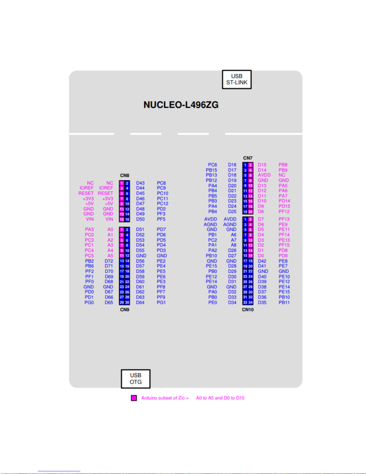
Figure 16 – Nucleo-L496ZG Arduino Pinouts (Right-Side)
Page 22

Page 22
16 Contact Info and Technical Support
Documentation and reference designs are available for download from the product page:
http://cloudconnectkits.org/product/telus-iot-starter-kit
Instructional blog on how to Build an Azure IoT Client using Mbed OS
http://avnet.me/azure-iot-mbed-client
For further info on Avnet-designed Starter Kits, contact your local Avnet representative at:
eval.kits@avnet.com
Telus network connectivity support is available via TELUS online Live Chat at:
https://www.telus.com/en/on/business/contact-telus
17 Disclaimer
Avnet assumes no liability for modifications that the user chooses to make to their BG96 Shield or the
STM32 NUCLEO and X-NUCLEO boards provided in Telus LTE-M IoT Starter Kits
Page 23

Page 23
Appendix-A: Standalone LTE-M Modem Test (Optional)
Note! The following two optional “standalone tests” utilize just the BG96 Shield on it’s own.
1) Check the configuration switches are set to the default positions tabled earlier in this document
2) The BG96 Shield has been fitted with a preconfigured eSIM device. If needing to use a removable SIM
card, then SW4 must be set accordingly and the SIM should be activated on the carrier’s website
3) To insert a SIM card, slide the metal retaining clip in direction of the Push-button switch, then lift this up
and insert the SIM with notched corner facing outwards. Lock the SIM into place by pressing on the SIM
holder and sliding the metal retaining clip back in the other direction.
4) Attach the LTE antenna to the SMA connector next to the USB connector the BG96 board.
Attach the GPS antenna to the SMA connector next to PWRKEY button switch on the BG96 board
Both SMA connectors should be “finger-tightened”
5) Open Windows Device Manager, expand the Ports (COM & LPT) section
6) Standalone operation as a modem to your computer, requires a Quectel USB driver.
Download and extract Quectel_LTE_Windows_USB_Driver_V1.0.zip to your Windows computer
7) Attach a USB cable between the microUSB connector on the BG96 Shield and your Windows computer
(The BG96 board must be used standalone, not stacked onto the Nucleo boards)
8) Installation of the USB driver requires that the BG96 Shield is connected and awake
Press and hold the S1 PWRKEY button switch for 2 seconds…
Three new COM ports should now be listed under the Ports section of Windows Device Manager
Figure 17 – BG96 COM ports Reported in Device Manager
9) Once confirmed that the USB interfaces have enumerated, open the Tera Term serial console
application on your Windows computer
10) Press ALT+N (or use File New Connection) to open the New Connection dialog.
Select Serial, then the COM Port labelled Quectel USB AT Port
11) Configure the serial port settings (Setup Serial Port) to: 115200 8N1
Save the serial port settings (Setup Save Setup)
Page 24

Page 24
12) Click on main pane of the console window, then exercise the board by entering the following AT
commands… (These can also be sent using the BG96_FAT_TEST.TTL Tera Term macro file)
ATI
AT+GSN
AT+CFUN=1
AT+QCCID
AT+COPS=0
AT+QCFG="NWSCANSEQ",020301
AT+QCFG="IOTOPMODE",0
AT+QCFG="BAND",0,80A,80A
AT+CSQ
AT+COPS=?
13) Responses to these AT commands should be similar to what is shown below…
Page 25

Page 25
Appendix-B: Standalone GPS Test (Optional)
The following three AT commands can be used to perform a quick check of the GPS receiver
AT+QGPS=1 // Turn-on GNSS
AT+QGPSLOC? // Acquire the positioning info
AT+QGPSEND // Turn-off GNSS
For a more interactive visual test of the GPS capability,
it is recommended that you download a Windows
GPS application such as VisualGPS or VisualGPSView
http://www.visualgps.net/#visualgps-content
http://www.visualgps.net/#visualgpsview-content
The Windows VisualGPS application is then
connected to the NMEA USB serial port of the
BG96 module (baudrate = 115200) for direct
access to the NMEA messages
(ie. not the Modem AT Command serial port!)
 Loading...