

Page 1

Ultra96-V2 Getting Started Guide
Version 1.0
Page 1
Copyright © 2019 Avnet, Inc. AVNET, “Reach Further,” and the Avnet logo are registered
trademarks of Avnet, Inc. All other brands are the property of their respective owners.
LIT# Ultra96-V2-GSG-v1-0
Page 2

Document Control
Document Version: 1.0
Document Date: 25 Jun 2019
Prior Version History
Version Date Comment
1.0 25 Jun 2019 Initial Ultra96-V2 Getting Started Guide (30 May 2019 image)
Page 2
Page 3

Contents
1 Getting Started with Ultra96-V2 ............................................................................ 5
2 What’s Inside the Box? ......................................................................................... 6
2.1 Optional add-on items: ............................................................................................................. 6
3 What’s on the Web?.............................................................................................. 7
3.1 Official Documentation: ............................................................................................................ 7
3.2 Tutorials and Reference Designs: ............................................................................................ 7
3.3 Trainings and Videos: ............................................................................................................... 7
4 Ultra96-V2 Key Features ...................................................................................... 8
5 Ultra96-V2 Basic Setup and Operation ............................................................... 10
6 Example Design .................................................................................................. 11
7 Hardware Setup .................................................................................................. 11
8 Power Up and Connect to Wi-Fi ......................................................................... 14
9 Ultra96-V2 GPIO LEDs Example Project ............................................................ 18
10 Example Projects ................................................................................................ 20
11 Custom Content Tutorial ..................................................................................... 21
12 Using Ultra96-V2 Tutorial .................................................................................... 22
13 Access Ultra96-V2 Linux Terminal over SSH ..................................................... 23
14 Power Off ............................................................................................................ 26
15 Getting Help and Support ................................................................................... 27
15.1 Avnet Support ......................................................................................................................... 27
15.2 Xilinx Support ......................................................................................................................... 28
16 Installing and Licensing Xilinx Software .............................................................. 29
16.1 Install Vivado Design Suite, Design Edition ........................................................................... 29
17 Certification Disclaimer ....................................................................................... 33
18 Safety Warnings ................................................................................................. 33
19 RF Certification ................................................................................................... 33
Page 3
Page 4

Figures
Figure 1 – Ultra96-V2 .................................................................................................. 5
Figure 2 – Ultra96-V2 Block Diagram .......................................................................... 9
Figure 3 – Ultra96-V2 Topology ................................................................................ 10
Figure 4 – Ultra96-V2 SW3 Boot Mode Switch Location ........................................... 11
Figure 5 – Ultra96-V2 with JTAG/UART Pod ............................................................ 12
Figure 6 – JTAG/UART Pod Alignment ..................................................................... 12
Figure 7 – Ultra96-V2 Booted .................................................................................... 14
Figure 8 – Successful Wi-Fi Connection on Ultra96-V2 ............................................ 16
Figure 9 – Find the IP Address .................................................................................. 16
Figure 10 – Connected to Ultra96-V2 Webserver ..................................................... 17
Figure 11 – Ultra96-V2 GPIO LEDs .......................................................................... 18
Figure 12 – Ultra96-V2 User LEDs ............................................................................ 18
Figure 13 – Mapping from Web Page to Actual LED ................................................. 19
Figure 14 – Example Projects Under Construction ................................................... 20
Figure 15 – Ultra96-V2 Tutorials/Guides ................................................................... 21
Figure 16 – TeraTerm New Connection .................................................................... 23
Figure 17 – SSH Terminal Settings ........................................................................... 24
Figure 18 – Click Continue ........................................................................................ 24
Figure 19 – SSH Authentication ................................................................................ 25
Figure 20 – Ultra96-V2 Terminal ............................................................................... 25
Figure 21 – Power Down Initiated Through Short Press of SW4 ............................... 26
Figure 22 – Voucher Confirmation ............................................................................ 30
Figure 23 – Generate Node-Locked .......................................................................... 30
Figure 24 – Select Host Information .......................................................................... 31
Page 4
Page 5
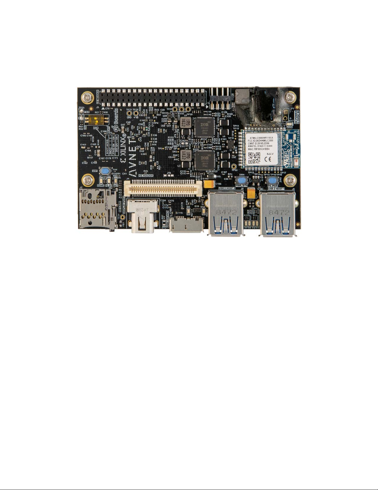
1 Getting Started with Ultra96-V2
The Avnet Ultra96-V2 enables hardware and software developers to explore the capabilities of
the Zynq® UltraScale+™ MPSoC. Designers can create or evaluate designs for both the Zynq
Processor Subsystem (PS) and the Programmable Logic (PL) fabric.
Figure 1 – Ultra96-V2
This Getting Started Guide will outline the steps to setup the Ultra96-V2 hardware. It documents
the procedure to run a Linux design running on the Quad-core ARM Cortex-A53 MPCore
Processing System (PS).
Page 5
Page 6

2 What’s Inside the Box?
Ultra96-V2 development board
16GB microSD card with SD adapter and jewel case
Voucher for SDSoC license from Xilinx
Quick Start Instruction card
2.1 Optional add-on items:
External 96Boards compliant power supply kit (12V, 4A, International plugs)
o AES-ACC-U96-4APWR
o http://avnet.me/96boardpower4A
USB-to-JTAG/UART pod for Ultra96-V2
o AES-ACC-U96-JTAG
o http://avnet.me/Ultra96JTAG
96Boards Click Mezzanine for adding Click boards to the Ultra96-V2
o Mezzanine only -- AES-ACC-U96-ME-MEZ
o Starter kit including 3 Click boards -- AES-ACC-U96-ME-SK
o http://avnet.me/ClickMezzanine
miniDP-to-HDMI adapter or cable
o Must be an Active adapter or cable
See the Ultra96-V2 Compatible Accessories document and http://avnet.me/Ultra96_Accessories for
other suggestions.
Page 6
Page 7

3 What’s on the Web?
Ultra96-V2 is a community-oriented kit, with all materials being made available through the
http://avnet.me/ultra96-v2 community website.
3.1 Official Documentation:
Getting started guide
Hardware user guide
Schematics
Bill of materials
Mechanical drawing
3D Model
Board definition files for Vivado integration available at https://github.com/Avnet/bdf.
Programmable logic (PL) master user constraints
3.2 Tutorials and Reference Designs:
TBD
3.3 Trainings and Videos:
Live and On-Demand Technical Training Courses at http://avnet.me/TTC
Page 7
Page 8

4 Ultra96-V2 Key Features
Zynq UltraScale+ MPSoC ZU3EG SBVA484
Memory
o Micron 2 GB (512M x32) LPDDR4 Memory
o microSD Socket
Ships with Delkin Utility MLC 16GB card
Wi-Fi / Bluetooth
DisplayPort
1x USB 3.0 Type Micro-B upstream port
2x USB 3.0 Type A downstream ports
40-pin Low-speed expansion header
60-pin High speed expansion header
Mounted on thermal bracket with fan
Note that there is no on-board, wired Ethernet interface. All communications must be done
via USB, Wi-Fi, JTAG, or expansion interface.
Page 8
Page 9
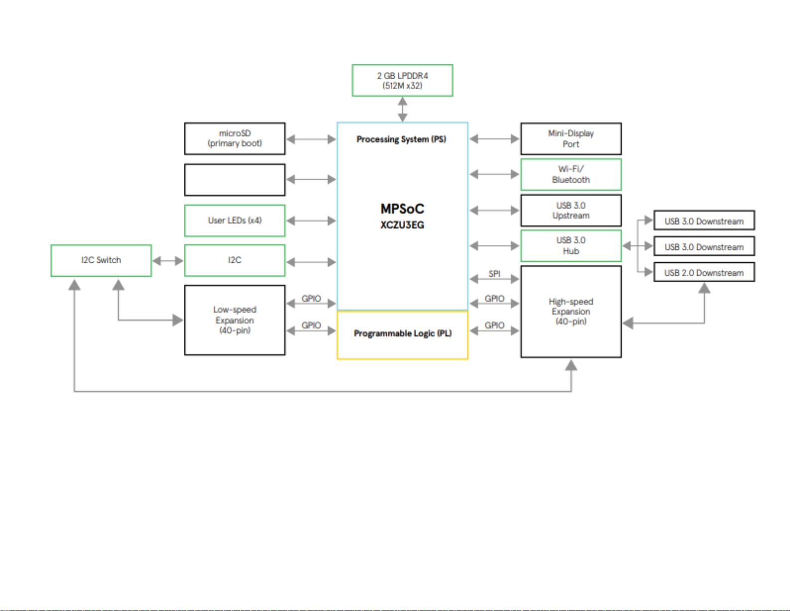
UART
(4-pin header)
Figure 2 – Ultra96-V2 Block Diagram
Page 9
Page 10
5 Ultra96-V2 Basic Setup and Operation
The functionality of the Ultra96-V2 is determined by the application booted from the non-volatile
memory – by default that is the microSD Card. This Getting Started Guide allows system
developers to exercise and demonstrate multiple circuits through PetaLinux, including:
SSH Terminal Access
GPIO LEDs
Wi-Fi
In addition to the items included in the kit, you will also need the following to complete the
exercises in this tutorial.
Ultra96 USB-to-JTAG/UART Pod (required for terminal access)
o or
Monitor (requires connection to miniDP port), keyboard, mouse
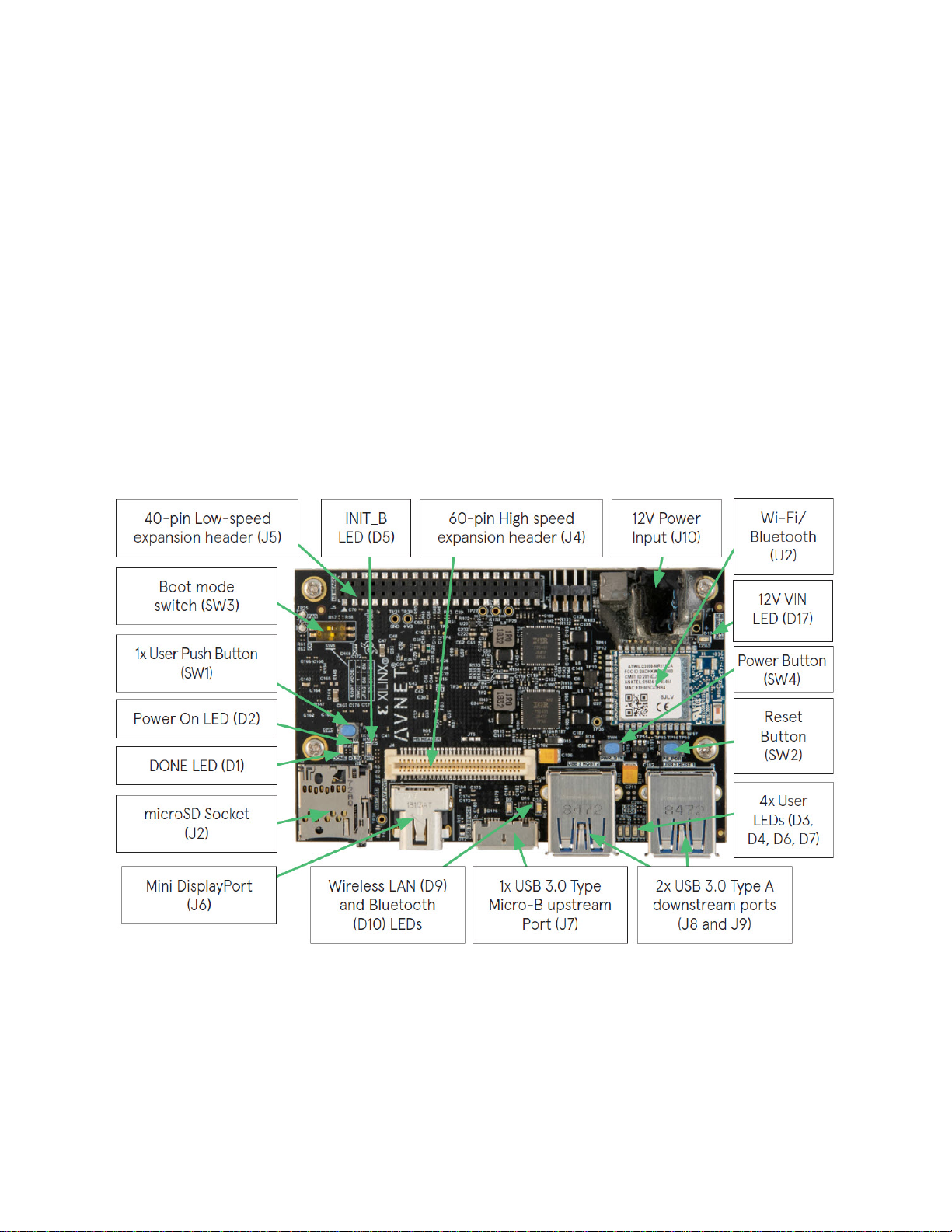
An Ultra96-V2 image in its expected out-of-box configuration is shown below along with various
topology components highlighted.
Figure 3 – Ultra96-V2 Topology
Page 10
Page 11

6 Example Design
The Ultra96-V2 example design must first be written to the 16GB microSD Card, which ships
blank.
1. Please download the image and instructions at http://avnet.me/ultra96-v2-oob
2. Complete the process to write the image to your 16GB card.
3. Insert the microSD card into the Ultra96-V2 card cage J2.
7 Hardware Setup
1. A terminal program is required. TeraTerm was used in this example which can be
downloaded from the TeraTerm project on the SourceForge Japan page:
ttssh2.sourceforge.jp Install TeraTerm or another terminal program of your choice.
2. Set the Ultra96-V2 boot mode switch SW3 to SD Card boot mode as shown below with
Switch 1 in the OFF position and Switch 2 in the ON position.
Figure 4 – Ultra96-V2 SW3 Boot Mode Switch Location
Page 11
Page 12

3. If you will be using a USB-to-JTAG/UART Pod, plug that into J1 and J3 before plugging
in 12V power. Note that some Pods only have a 3-pin and 7-pin receptacles, which is
compatible with the 4-pin and 8-pin headers on Ultra96-V2 (align as seen in Figure 6
below).
Figure 5 – Ultra96-V2 with JTAG/UART Pod
Figure 6 – JTAG/UART Pod Alignment
Page 12
Page 13

4. Plug in your 12V Barrel Jack power supply into a wall outlet and then connect the barrel
jack to J10 on your Ultra96-V2. Green Vin status LED D17 will light, but the board is not
yet powered on.
Note: DC power supply is not included in the Ultra96-V2 kit but can be purchased
separately.
The Ultra96 USB-to-JTAG/UART Pod ships with pre-programmed firmware that allows the
JTAG interface to be recognized by Xilinx Vivado software. Additionally, most host machines will
also automatically install the driver for the Serial Terminal interface.
5. Plug a microUSB cable between the Pod’s microUSB Port (J1) and a host computer.
6. If the serial terminal drivers do not automatically install, you can manually install the
driver for the FT2232H device. Visit www.ftdichip.com/Drivers/VCP.htm then download
and install the appropriate driver for your operating system.
7. Launch your Serial Terminal with settings of 115200-8-N-1.
Page 13
Page 14

8 Power Up and Connect to Wi-Fi
1. Press and release the power button (SW4). The Green Power On LED (D2), Red INIT_B
LED (D5) and the Green User LEDs should illuminate. After a few seconds, INIT_B LED
will turn off and the Blue DONE LED (D1) will illuminate. You will immediately see output
to the terminal screen as Linux boots. At ~30 seconds, the Green User LED D7 will blink
in a heartbeat fashion.
2. You can ignore the Bluetooth warnings as shown below. Hit the enter key to get to the
prompt.
Figure 7 – Ultra96-V2 Booted
3. Login using username = “root” and password = “root”
4. You should already be in the home directory /home/root. If not, then enter the following
command:
cd /home/root
5. Now list the contents of that directory.
ls
6. You should observe that there are 4 files present. We will use both the
wpa_supplicant.conf and wifi.sh files to bring up the Wi-Fi.
a) ble.sh
b) bt.sh
c) wifi.sh
d) wpa_supplicant.conf
Page 14
Page 15

7. Before bringing up the Wi-Fi interface you must first edit the
/home/root/wpa_supplicant.conf file with the correct SSID and security
password for your Wi-Fi access point. You can use the built-in vi editor to do this.
vi wpa_supplicant.conf
a) If you are not familiar with vi, the easiest thing to do is to edit the SSID_here and
password_here fields in the following lines in a text editor, then copy to your
clipboard.
ctrl_interface=/var/run/wpa_supplicant
ctrl_interface_group=0
update_config=1
network={
key_mgmt=WPA-PSK
ssid="RCK_MY_WRLD"
psk="AABBCCDDEEFF00112233445566"
}
b) Enter the following commands into vi:
i. 9dd
ii. i
iii. <paste command> -- in TeraTerm it is Alt-V
iv. ESC key
v. :wq
8. Once that is done, run the supplied wifi.sh script to copy the wpa_supplicant.conf file to
/etc, load the kernel modules for the driver, and bring up the Wi-Fi interface:
./wifi.sh
9. If successful, move on to step 13. If it fails due to bad SSID or password, you may see
the following message. Work through the following steps to correct it.
Successfully initialized wpa_supplicant
ctrl_iface exists and seems to be in use - cannot override it
Delete '/var/run/wpa_supplicant/wlan0' manually if it is not used anymore
Failed to initialize control interface '/var/run/wpa_supplicant'.
You may have another wpa_supplicant process already running or the file was
left by an unclean termination of wpa_supplicant in which case you will need
to manually remove this file before starting wpa_supplicant again.
10. Enter this command to remove the reference to wlan0
rm /var/run/wpa_supplicant/wlan0
Page 15
Page 16

11. Edit /home/root/wpa_supplicant.conf again to correct the mistake
12. Run the wifi.sh script again.
./wifi.sh
13. A successful connection should appear like the following:
Figure 8 – Successful Wi-Fi Connection on Ultra96-V2
14. Use ifconfig to determine the IP address assigned to the board.
ifconfig
Figure 9 – Find the IP Address
Page 16
Page 17

15. Open a browser using a machine connected to the same network, and then browse to
the IP address of the board. The browser page will show like below.
Figure 10 – Connected to Ultra96-V2 Webserver
Note that this design is still in the process of being updated. The MAC Address is correct, but
the IP Address is not. Also, many of the tutorials are not functional yet. We will release a new
image with updates and corrections in July 2019.
Page 17
Page 18

9 Ultra96-V2 GPIO LEDs Example Project
1. Next we want to access the Ultra96-V2 GPIO LEDs example project. From the Ultra96V2 home page select Ultra96 GPIO LEDs example project
Figure 11 – Ultra96-V2 GPIO LEDs
Be aware that the photo on this page and the LED reference designators is the older Ultra96V1. The new Ultra96-V2 LEDs are D3, D4, D6, and D7, shown below:
Figure 12 – Ultra96-V2 User LEDs
Page 18
Page 19

2. All LEDs will be at an unknown state to begin with. Select the drop down menus and
begin changing the status of the GPIO LEDs. You will notice that the four LEDs (located
in between the two USB connectors J8/J9) update in real time. See the mapping below.
For example, if you change the pull-down for LED2/DS5, then LED D7 which is closest
to USB Connector J8 will be the one to change.
Figure 13 – Mapping from Web Page to Actual LED
3. Scroll to the bottom of the webpage and you will see a definition table for various LED
selection options.
Page 19
Page 20

10 Example Projects
Unfortunately, the Example Projects besides the GPIO LEDs are still under construction.
Figure 14 – Example Projects Under Construction
Page 20
Page 21

11 Custom Content Tutorial
1. Select the Tutorial tab at the top of the page. You will be directed to a Tutorials/Guides
page
Figure 15 – Ultra96-V2 Tutorials/Guides
2. This section goes into how to get started with the microSD card image we have been
exploring up to this point. As of now we have explored the Run Example Projects
section.
3. Let’s look at the Custom Content tutorial. Select Custom Content.
4. This Tutorial goes over the three different ways custom content can be added to this out
of box image. The three different ways being
1) Uploading custom files
2) Making custom webpages
3) Making custom projects
5. To access these options select the Custom Content tab at the top of the webpage.
Page 21
Page 22

12 Using Ultra96-V2 Tutorial
1. Click the Tutorials page. Select the Using Ultra96 tutorial
2. This tutorial goes over the various ways you can interact with the Ultra96-V2. As of now
we have interacted using the Webserver and UART on the Pod.
3. To explore your Ultra96-V2 over miniDP, you will need a compatible cable and monitor.
For example, the following combinations work:
miniDP-to-DP cable with DisplayPort Monitor
Active miniDP-to-HDMI cable with HDMI Monitor
4. Read through the SSH section, it states we can access the Ultra96-V2 terminal using
TeraTerm or a PuTTY terminal application.
5. Since we have already downloaded and installed TeraTerm at the beginning of this guide
let’s access the Ultra96-V2’s Linux terminal over SSH using TeraTerm
Page 22
Page 23

13 Access Ultra96-V2 Linux Terminal over SSH
1. Open TeraTerm and then select File New connection… as seen in the image below.
Figure 16 – TeraTerm New Connection
Page 23
Page 24

2. A new TeraTerm: New connection window will open. We now want to connect to
Ultra96-V2 over SSH, select TCP/IP and then configure your Terminal settings to use the
IP address that you discovered previously, similar to the below figure.
Figure 17 – SSH Terminal Settings
3. Select OK
4. If you get a SECURITY WARNING, click Continue to add this machine to the known
hosts list.
Figure 18 – Click Continue
Page 24
Page 25

5. You will then be prompted to enter SSH Authentication information. In our case it is
looking for the Linux terminal’s user name and passphrase which are root and root.
6. Please type in root for the User name and then type in root for the Passphrase as well.
Then select OK.
Figure 19 – SSH Authentication
7. You now have access to the Ultra96-V2 Terminal!
Figure 20 – Ultra96-V2 Terminal
Page 25
Page 26

14 Power Off
When you are done experimenting with your Ultra96-V2 and wish to power off the board, there
are several ways to power off the board. You can do it from the command line with a ‘shutdown h now’ command. However, we will have you take advantage of the on-board On/Off Controller
that interacts with the MPSoC Power Management Unit to initiate a controlled shutdown.
1. Press and release the Power button (SW4) located on the top side of your Ultra96-V2
next to USB port J8.
2. You will notice your board does not power down immediately. It will take roughly 10-20
seconds for your board to completely power down. The reason behind this is it is adhering
to the various power down sequencing requirements. See the message in the terminal
as shown.
Figure 21 – Power Down Initiated Through Short Press of SW4
3. Please note, if you do not let your Ultra96-V2 power off as per the power down
sequencing requirements (such as unplugging the barrel jack), your microSD Card may
get corrupted or damaged.
4. To force poweroff of the Ultra96-V2, you can also press and hold SW4 for 10 seconds.
This is useful for when the soft power-off doesn’t work.
Page 26
Page 27

15 Getting Help and Support
15.1 Avnet Support
TheUltra96‐V2isaversatiledevelopmentkitthatallowsevaluationoftheZynqMPSoC,which
canhelpyouadoptZynqintoyournextdesign.Alltechnicalsupportisofferedthrough
http://avnet.me/Ultra96_Forum.Ultra96‐V2usersareencouragedtoparticipateintheforums
andofferhelptootherswhenpossible.
ToaccessthemostcurrentcollateralforUltra96‐V2pleasevisitthecommunitysupportpage
at:
http://avnet.me/ultra96‐v2
ToaccessthelatestUltra96‐V2documentation,clickontheViewAlllinkunderDocumentation:
ToaccessthelatestreferencedesignsforUltra96‐V2,clickontheViewAlllinkunderReference
Designs:
ToaccesstheUltra96‐V2technicalforums,gotohttp://avnet.me/Ultra96_Forum.
Toviewonlinetrainingandvideos,gotohttp://avnet.me/TTC.
Page 27
Page 28

15.2 Xilinx Support
ForquestionsregardingproductswithintheProductEntitlementAccount,visittheContact
SupportsiteforXilinx:
https://www.xilinx.com/support/service‐portal/contact‐support.html
Fortechnicalsupportincludingtheinstallationanduseoftheproductlicensefile,contactXilinx
OnlineTechnicalSupportatwww.xilinx.com/support.Thefollowingassistanceresourcesarealso
availableonthewebsite:
Software, IP and documentation updates
Access to technical support web tools
Searchable answer database with over 4,000 solutions
User forums
Page 28
Page 29

16 Installing and Licensing Xilinx Software
16.1 Install Vivado Design Suite, Design Edition
The Zynq device on the Ultra96-V2 is supported in Vivado Design Suite, Design Edition. Version
2018.1 or later is required to use the board definition file provided on the Avnet GitHub.
You must license your Vivado Design Suite, Design Edition with the license that came with your
Ultra96-V2. To obtain your free license, visit the following website and insert the voucher code
from the certificate included in your kit:
http://www.xilinx.com/getlicense
1. Log in
2. Fill out information at Product Licensing - Name and Address Verification, then click
Next
3. Select your Account
4. Enter your voucher code here, then click Redeem Now.
Page 29
Page 30

5. At the confirmation screen, click Yes.
Figure 22 – Voucher Confirmation
6. Under Certificate Based Licenses, find OEM Zynq ZU3 Ultra96 Vivado Design Edition
Voucher pack and check the box. Now click Generate Node-Locked License.
Figure 23 – Generate Node-Locked
Page 30
Page 31

7. Create or select your Host ID. Click Next.
Figure 24 – Select Host Information
Page 31
Page 32

8. Review the license request, then click Next again.
If a full seat of Vivado System or Design Edition has already been installed, then no further
software will be needed. Please check online for any updates at:
www.xilinx.com/support/download/index.htm
For detailed instructions on installing and licensing the Xilinx tools, please refer to the latest
version of Vivado Design Suite User Guide Release Notes, Installation, and Licensing
(UG973).
Page 32
Page 33

17 Certification Disclaimer
Both CE and FCC certifications are necessary for system level products in those countries
governed by these regulatory bodies.
Because Avnet boards are intended for evaluation kits only and destined for professionals (you)
to be used solely at research and development facilities for such purposes, they are considered
exempt from the EU product directives and normally are not tested for CE or FCC compliance.
If you choose to use your board to transmit using an antenna, it is your responsibility to make
sure that you are in compliance with all laws for the country, frequency, and power levels in
which the device is used. Additionally, some countries regulate reception in certain frequency
bands. Again, it is the responsibility of the user to maintain compliance with all local laws and
regulations.
This board should be used in a controlled lab environment by professional developers for
prototype and development purposes only. The board included in the kit is not intended for
production use unless additional end product testing and certification is performed.
18 Safety Warnings
This product shall only be connected to an external power supply that is 96boards compliant.
Only compatible plug-in modules shall be connected to Ultra96-V2. The connection of incompatible devices
may affect compliance or result in damage to the unit and void the warranty.
This product shall be operated in a well-ventilated environment. If a case is used, it shall have adequate
ventilation.
19 RF Certification
The frequency range is 2.412GHz ~ 2.472GHz (2.4GHz ISM Band).
The radio is IEEE 802.11 b/g/n (1x1) compliant for up to 72 Mbps PHY rate
The ATWILC3000-MR110CA has regulatory approval in more than 75 countries around the
world. More information on RF certification for the Microchip ATWILC3000 module is available
here:
http://ww1.microchip.com/downloads/en/DeviceDoc/ATWILC3000MR110CA%20Worldwide%20Regulatory%20Information.pdf
Page 33
 Loading...