

Page 1
Page 1
Copyright © 2017 Avnet, Inc. AVNET, “Reach Further,” and the Avnet logo are registered
trademarks of Avnet, Inc. All other brands are the property of their respective owners.
LIT# MiniZed-GSG-v1-1-V1
MiniZed Getting Started Guide
Version 1.2
Page 2

Page 2
Version
Date
Comment
1.0
12 Jun 2017
Initial MiniZed Hardware User Guide
1.1
22 Jun 2017
Fixed a formatting problem with Appendix A
1.2
21 May 2018
Fixed an error about the USB stick on page 10
Document Control
Document Version: 1.2
Document Date: 21 May 2018
Prior Version History
Page 3

Page 3
Contents
Getting Started with MiniZed ................................................................................. 6
What’s Inside the Box? ......................................................................................... 7
Optional add-on items: ............................................................................................................. 7
What’s on the Web? ............................................................................................. 7
Official Documentation: ............................................................................................................ 7
Tutorials and Reference Designs: ............................................................................................ 7
Trainings and Videos: ............................................................................................................... 7
Available through Avnet FAE: .................................................................................................. 7
MiniZed Key Features ........................................................................................... 8
MiniZed Basic Setup and Operation ................................................................... 10
Example Design ..................................................................................................................... 11
Hardware Setup ...................................................................................................................... 11
Boot Linux ........................................................................................................... 13
Reading from USB .............................................................................................. 15
Wi-Fi ................................ ................................................................ ................... 16
Bluetooth ............................................................................................................. 24
I2C Sensor and GPIO ......................................................................................... 25
Linux File System ............................................................................................... 27
Poweroff .............................................................................................................. 30
Getting Help and Support ................................................................................... 31
Avnet Support ......................................................................................................................... 31
Xilinx Support ......................................................................................................................... 32
Installing and Licensing Xilinx Software .............................................................. 33
Install Vivado Design Suite, WebPack Edition ....................................................................... 33
Certification Disclaimer ................................................................ ....................... 34
Regulatory Compliance Information .................................................................... 35
Safety Warnings ................................................................................................. 36
RF Certification ................................................................................................... 37
Appendix A – Partition and Format eMMC .......................................................... 38
Page 4

Page 4
Figures
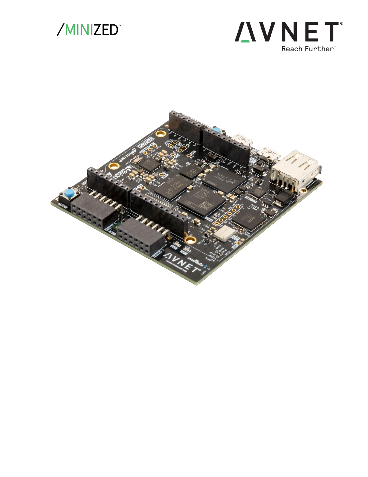
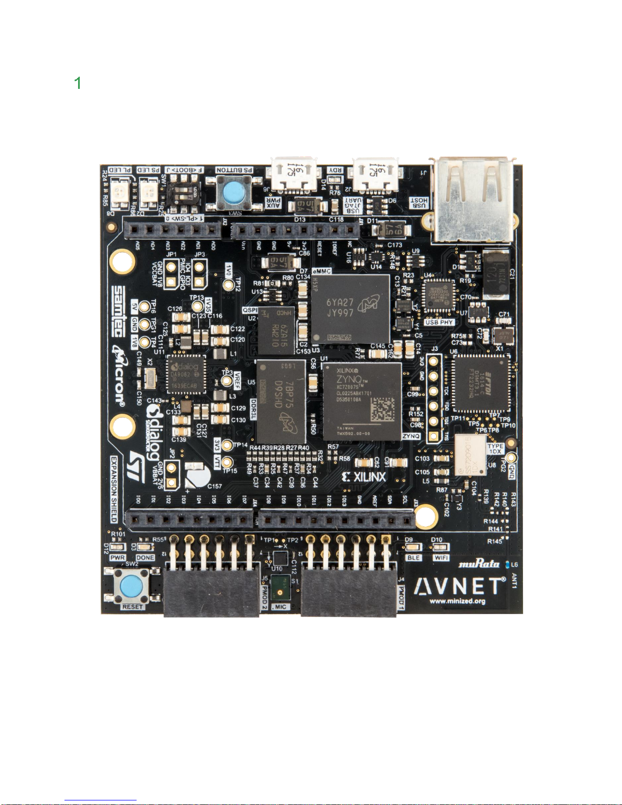
Figure 1 – MiniZed ...................................................................................................... 6
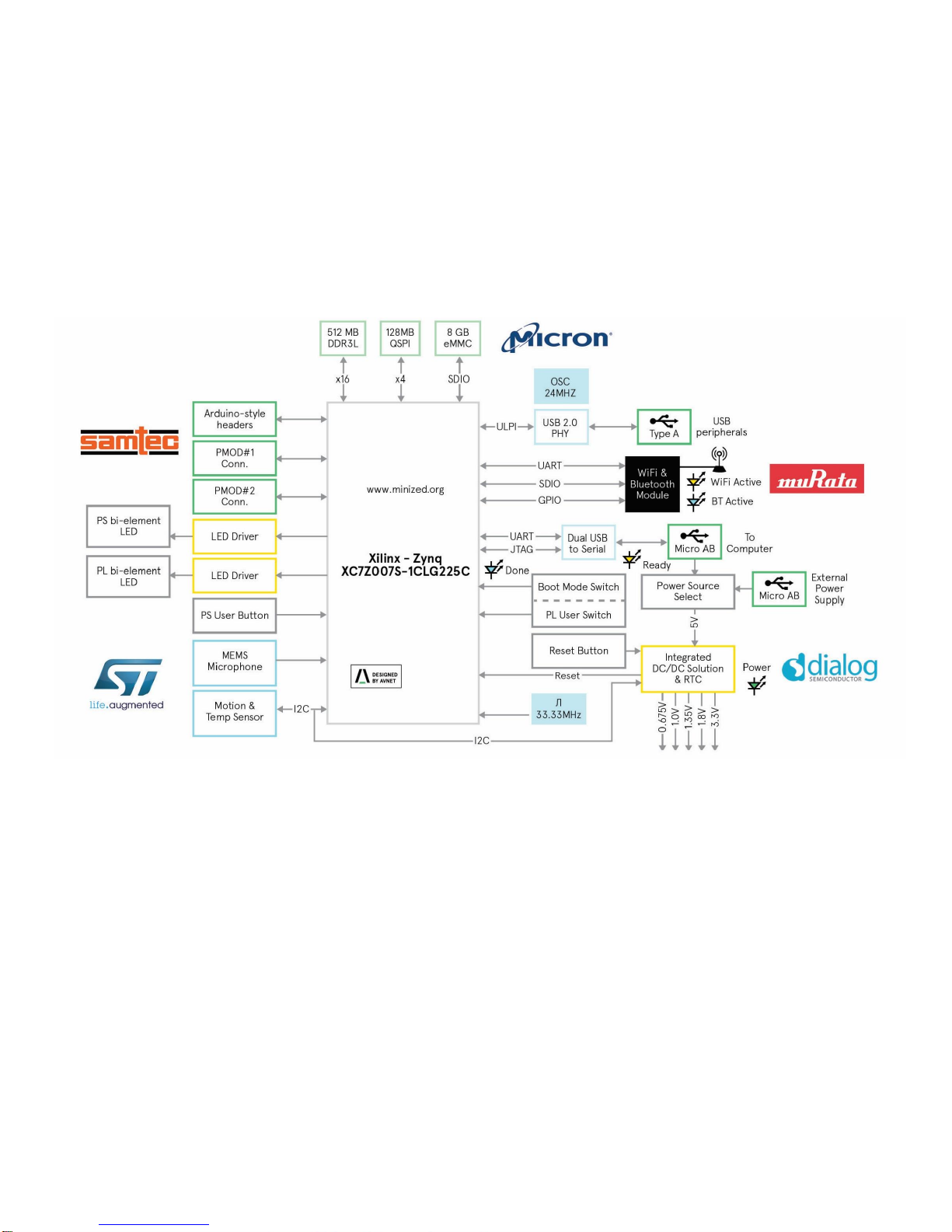
Figure 2 – MiniZed Block Diagram .............................................................................. 9
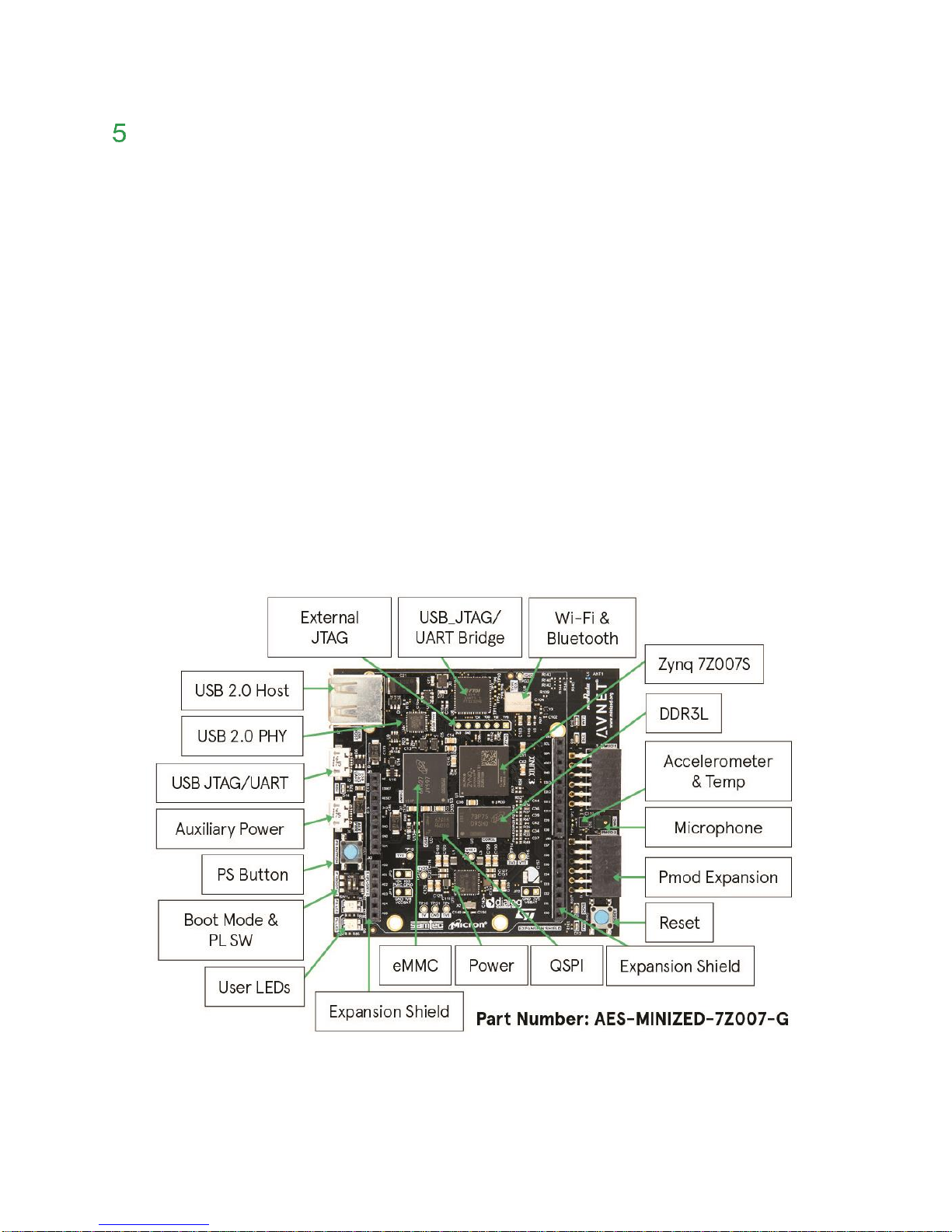
Figure 3 – MiniZed Topology ..................................................................................... 10
Figure 4 – MiniZed USB-JTAG/UART Installed Correctly ......................................... 11
Figure 5 – MiniZed Switch Location .......................................................................... 12
Figure 6 – QSPI/Flash Boot Mode ............................................................................ 13
Figure 7 – COM Port Settings for USB-UART Terminal ............................................ 13
Figure 8 – PetaLinux Boot on MiniZed ................................................................ ...... 14
Figure 9 – USB Drive Recognized ............................................................................ 15
Figure 10 – USB Drive Mounted ............................................................................... 15
Figure 11 – Edit these 2 fields in wpa_supplicant.conf .............................................. 16
Figure 12 – iperf results on MiniZed .......................................................................... 17
Figure 13 – ping results ............................................................................................. 18
Figure 14 – Download and View Text File ................................................................. 19
Figure 15 -- ifconfig ................................................................................................... 20
Figure 16 – MiniZed FTP Session ............................................................................. 21
Figure 17 – WinSCP Launched ................................................................................. 22
Figure 18 – WinSCP Parameters Entered ................................................................. 22
Figure 19 – WinSCP Save Session ........................................................................... 23
Figure 20 – MiniZed Bluetooth Discovers V20 Android ............................................. 24
Figure 21 – Testing LEDs, Button, Switch, and Sensor............................................. 25
Figure 22 – USER DIP set towards Push Button ...................................................... 25
Figure 23 – Print Working Directory .......................................................................... 27
Figure 24 – List Contents .......................................................................................... 27
Figure 25 – Detailed List Contents ............................................................................ 28
Figure 26 – Disk Free ................................................................................................ 28
Figure 27 – Find a File .............................................................................................. 29
Figure 28 – Which ..................................................................................................... 29
Figure 29 – fdisk started ............................................................................................ 38
Figure 30 – View Partitions ....................................................................................... 38
Figure 31 – Partition 1 Deleted .................................................................................. 39
Figure 32 – 128 MB Primary Partition Created .......................................................... 39
Page 5

Page 5
Figure 33 – Partition #2 ............................................................................................. 39
Figure 34 – New Partitions ........................................................................................ 39
Figure 35 – Partition Type Set to FAT32 ................................................................... 40
Figure 36 – Partition Table Written ............................................................................ 40
Figure 37 – eMMC Partitions Mounted ...................................................................... 41
Page 6
Page 6
Getting Started with MiniZed
The Avnet MiniZed enables hardware and software developers to explore the capabilities of the
Zynq™-7000 All Programmable SoC Single-Core. Designers can create or evaluate designs for
both the Zynq Processor Subsystem (PS) and the Programmable Logic (PL) fabric.
This Getting Started Guide will outline the steps to setup the MiniZed hardware. It documents
the procedure to run a PetaLinux design running on the ARM® Cortex™-A9 MPCore™
Processing System (PS).
Figure 1 – MiniZed
Page 7

Page 7
What’s Inside the Box?
MiniZed development board
Voucher for SDSoC license from Xilinx
Micro USB cable
Quick Start Instruction card
Safety Instructions pamphlet
Optional add-on items:
External 2A @ 5V power supply with micro USB cable (AES-ACC-MINIZ-PWR)
Digilent SD Card Pmod with SD Card (410-123)
ST Micro Motion MEMS and environmental sensor expansion board (X-NUCLEO-
IKS01A1)
What’s on the Web?
MiniZed is a community-oriented kit, with all materials being made available through the
MiniZed.org community website.
Official Documentation:
Getting started guide
Hardware user guide
Schematics
Bill of materials
Layout
PCB net lengths
Mechanical drawing
3D Model
Board definition files for Vivado integration
Programmable logic (PL) master user constraints
Tutorials and Reference Designs:
Introduction to Zynq Design Tutorials
PetaLinux BSP
Booting MiniZed using QSPI and eMMC
Trainings and Videos:
Introduction to MiniZed
Available through Avnet FAE:
Altium source database for schematic and layout
Page 8

Page 8
MiniZed Key Features
Xilinx Zynq XC7Z007S SoC
Memory
o Micron 512 MB DDR3L
o Micron 128 MB QSPI flash
o Micron 8GB eMMC mass storage
Configuration and Debug
o On-board USB to JTAG and debug UART circuit
Communications
o On-board USB to JTAG and debug UART circuit
o Murata "Type 1DX" wireless module with 802.11b/g/n Wi-Fi and Bluetooth 4.1
plus EDR and BLE (Bluetooth Low Energy)
o USB 2.0 host interface
Power
o Dialog Semiconductor DA9062 PMIC (Power Management IC)
Expansion connectors
o Arduino-compatible shield interface
o 2 x Pmod-compatible interfaces
Sensors
o ST Micro LIS2DS12 Accelerometer and Temperature sensor
o ST Micro MP34DT05 digital MEMS microphone
General Purpose I/O
o Reset button
o User button
o User switch
o Two user bi-element LEDs
Page 9
Page 9
Figure 2 – MiniZed Block Diagram
Page 10
Page 10
MiniZed Basic Setup and Operation
The functionality of the MiniZed is determined by the application booted from the non-volatile
memory – by default that is the QSPI and eMMC. This Getting Started Guide allows system
developers to exercise and demonstrate multiple circuits through PetaLinux, including:
USB 2.0
eMMC
Wi-Fi
Bluetooth
I2C Sensor
Microphone
In addition to the items included in the kit, you will also need the following to complete the
exercises in this tutorial.
Wi-Fi connection
2nd micro-USB cable
USB thumb drive formatted as FAT or FAT32
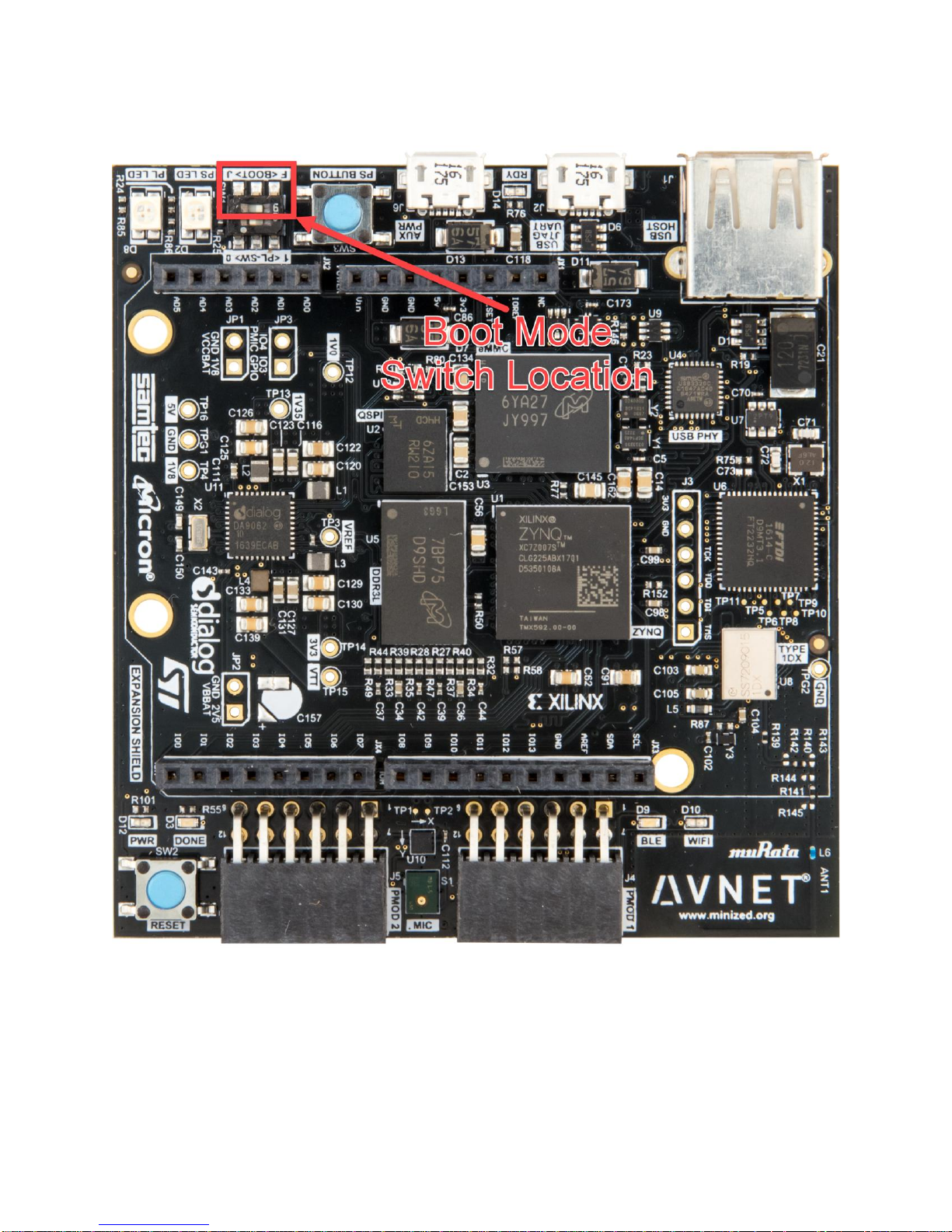
A MiniZed image in its expected out-of-box configuration is shown below along with the
locations of several key components.
Figure 3 – MiniZed Topology
Page 11
Page 11
Example Design
The MiniZed ships with an example PetaLinux design stored in the QSPI and eMMC. If the
QSPI has been erased or reprogrammed, than use the Restore QSPI and eMMC Factory
Images tutorial available at www.MiniZed.org to restore both the QSPI and eMMC to the original
factory images.
Hardware Setup
1. The USB thumb drive must be formatted as FAT32. If this has not been previously done,
please do that now.
2. A terminal program is required. Tera Term was used in this example which can be
downloaded from the Tera Term project on the SourceForge Japan page:
ttssh2.sourceforge.jp Install Tera Term or another terminal program of your choice.
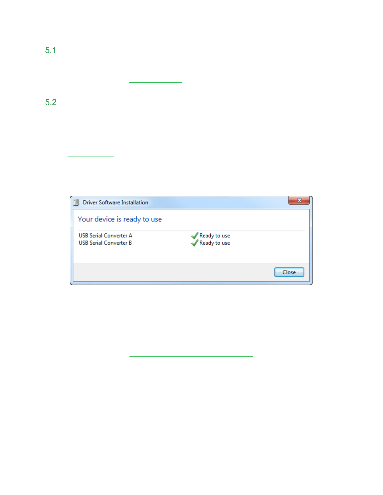
3. Connect the MiniZed USB-JTAG/UART port J2 to your Windows PC. It should
automatically install the proper drivers, giving you a confirmation as shown below. If
installed correctly, skip to Step 7.
Figure 4 – MiniZed USB-JTAG/UART Installed Correctly
4. In the rare circumstance that the drivers are not auto-installed, then you must manually
install the driver for the FTDI FT2232H device. Visit the FTDI website and download the
appropriate driver for your operating system.
http://www.ftdichip.com/Drivers/VCP.htm
5. Make sure the MiniZed is unplugged from the PC. Unzip and install the driver.
6. Reboot your PC then plug in the MiniZed.
Page 12
Page 12
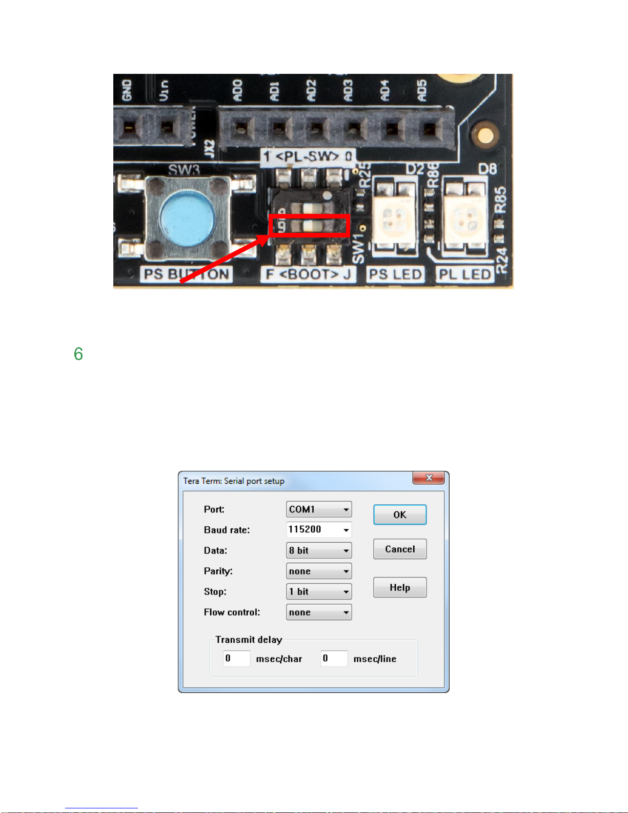
7. Set the MiniZed boot mode switch SW1 to QSPI mode (‘F’ for Flash) as shown below.
Figure 5 – MiniZed Switch Location
Page 13
Page 13
Figure 6 – QSPI/Flash Boot Mode
Boot Linux
8. If previously disconnected, plug in the micro-USB cable to the USB-JTAG/UART port.
9. Plug in the 2nd micro-USB cable to the auxiliary power port. This is necessary for the USB
thumb drive to get power.
10. Launch and connect Tera Term using the settings shown below. Press the RESET button
(SW2) to reset the board so you can see the boot sequence.
Figure 7 – COM Port Settings for USB-UART Terminal
Page 14

Page 14
Figure 8 – PetaLinux Boot on MiniZed
11. Login into the system with the following credentials (note that these credentials are set up
under the PetaLinux build environment, and we purposely chose very simple username
and password for this example).
Username: root
Password: root
This Linux image creates a “ramdisk” file system in the DDR3 on MiniZed. Basic Linux
commands are available as you might expect on any Linux system.
Page 15

Page 15
Reading from USB
12. Plug the USB thumb drive into MiniZed. Linux should recognize the drive and report status
to the terminal. Notice the USB device is labeled sda1.
Figure 9 – USB Drive Recognized
13. PetaLinux will also automatically mount the USB drive. Issue the ‘df’ command to see
where the USB drive was mounted. Use ‘ls’ to see if you recognize the contents.
root@plnx_arm:~# df
root@plnx_arm:~# ls /run/media/sda1
Figure 10 – USB Drive Mounted
The eMMC was previously partitioned and formatted when your board was tested. In fact, you
can see this in the ‘df’ command in Figure 10. The eMMC shows up as already mounted on
/run/media/mmcblk1p1. In the interest of time, we will use this existing formatted partition as
is. If you have time, you are welcome to learn about partitioning and formatting the eMMC in
Appendix A – Partition and Format eMMC at the end of this document.
Page 16

Page 16
14. You may copy images from the USB stick to the eMMC.
root@plnx_arm:~# cd /run/media/sda1
root@plnx_arm:~# ls
root@plnx_arm:~# cp file1 ../mmcblk1p1
root@plnx_arm:~# cp file2 ../mmcblk1p1
Wi-Fi
15. Prior to testing the Wi-Fi, you must edit the configuration file to match your wireless
settings. The config file is wpa_supplicant.conf and is located on the eMMC. You
must edit this file so that SSID and passcode (psk) match your wireless connection. You
can use the built-in editor vi to do this.
For a list of vi commands, refer to http://www.linfo.org/vi/summary.html
You may also copy wpa_supplicant.conf to the USB stick, then edit on your PC, then
copy back to the eMMC.
root@plnx_arm:~# vi /run/media/mmcblk1p1/wpa_supplicant.conf
Figure 11 – Edit these 2 fields in wpa_supplicant.conf
16. To test your Wi-Fi connection, several setup steps are required. To ease the burden of
typing, a script has been provided in the /usr/local/bin directory, which is in the
default search path. To view the script, use the cat command. View the comments in the
script to understand what the script is doing.
root@plnx_arm:~# cat /usr/local/bin/wifi.sh
17. Run the script to setup the Wi-Fi as shown below
root@plnx_arm:~# wifi.sh
When MiniZed connects with the network it will obtain an IP address and report it in the Tera
Term window as below.
Page 17

Page 17
18. Now run iperf in Server mode on the MiniZed side:
root@plnx_arm:~# iperf -s
19. To complete the test, you must also run the iperf Client side on your PC, connecting to the
displayed IP address. You can get iperf from the following site:
https://iperf.fr/iperf-download.php
20. First, make sure your PC is on the same Wi-Fi network as MiniZed. Also, turn off any
VPN or firewall that may prevent communication across the network. Open a CMD
window. Change directory to the location where you copied iperf. Then enter command
below, using the IP you discovered for MiniZed in the previous step.
iperf -c <IP_of_MiniZed>
Results are then displayed in Tera Term as well as in the CMD window, as shown below.
Figure 12 – iperf results on MiniZed
21. Use <Ctrl-C> to cancel iperf in Linux.
Page 18

Page 18
22. Note that this step will only work if the Wi-Fi access point is connected to the
internet.
Now try using ping to see if you can reach various internet sites using the DHCP server to
resolve the IP addresses.
root@plnx_arm:~# ping -c 3 <URL>
--- www.avnet.com
--- www.xilinx.com
--- www.google.com
--- www.amazon.com, etc.
Figure 13 – ping results
Page 19

Page 19
23. Note that this step will only work if the Wi-Fi access point is connected to the
internet.
Get a file from a host website and display it.
root@plnx_arm:~# wget http://www.textfiles.com/food/brdpudd.des
root@plnx_arm:~# cat brdpudd.des
Figure 14 – Download and View Text File
Page 20

Page 20
24. Use ifconfig to get information about the connection.
root@plnx_arm:~# ifconfig
Figure 15 -- ifconfig
25. Open a Windows Command Prompt.
26. Connect an FTP session to the remote host with the command
ftp <MiniZed IP>
27. Use the login root. You can use the ftp session to transfer files back and forth across the
network to MiniZed. Commands such as ‘cd’ , ‘ls’ , ‘pwd’ , ‘put’ , and ‘get’ are all
useful commands.
28. Close the ftp session using the quit command.
Page 21

Page 21
Figure 16 – MiniZed FTP Session
Page 22

Page 22
29. So far we have seen how files can be copied to and from MiniZed using a USB memory
stick or over Wi-Fi via FTP. Lastly, we will look at a secure copy mechanism that can
also be used with a graphical interface. WinSCP can be downloaded from
http://winscp.net. It can be run command line under Windows or Linux.
In Windows, browse to the WinSCP directory and double-click on WinSCP.exe.
Figure 17 – WinSCP Launched
30. Change the File protocol to SCP. Edit the Host name to match the IP address of
MiniZed. Use “root” for both the User name and Password.
Figure 18 – WinSCP Parameters Entered
Page 23

Page 23
31. Click Save. You can set the Site name to “MiniZed” if you would like. You can also
choose to Save password. Then click OK.
Figure 19 – WinSCP Save Session
32. Click Login. If you get a prompt about connecting to an unknown server, click .
33. On the left side pane of the WinSCP, which is the host, browse a directory containing a
file that you would like to transfer (for example, a new image.ub or .bin file for the QSPI).
On the MiniZed side, browse to /run/media/mmcblk1p1, which is the eMMC. Drag the
file to the eMMC side (or click F5) and click OK if prompted for permission.
Page 24

Page 24
Bluetooth
34. To test your bluetooth connection, several setup steps are required. To ease the burden
of typing, a script has been provided in the /usr/local/bin directory. To view the script,
use the cat command. View the comments in the script to understand what the script is
doing.
root@plnx_arm:~# cat /usr/local/bin/bt.sh
35. Turn on your phone’s Bluetooth and make it discoverable.
36. Enter the following to launch the Bluetooth setup script:
root@plnx_arm:~# bt.sh
Figure 20 – MiniZed Bluetooth Discovers V20 Android
If you would like to scan again, do NOT rerun the script or it will hang your system.
37. To rescan the system, you can rerun the hcitool command:
root@plnx_arm:~# hcitool scan
or, for Bluetooth Low Energy only devices:
root@plnx_arm:~# hcitool lescan
Use <Ctrl-C> to cancel a low-energy scan.
Page 25

Page 25
I2C Sensor and GPIO
To ease testing of several peripheral devices on your board, a user application, i2csensor, has
been built into image.ub.
38. To test the LEDs, button, switch, and I2C sensor on the board, enter
root@plnx_arm:~# i2csensor
Figure 21 – Testing LEDs, Button, Switch, and Sensor
39. Set the 2nd dip switch nearest the Arduino connector towards the LED. This puts both
LEDs into counting mode.
40. Press the PS push button (SW3) to blank the LEDs and restart the counter.
41. Set the 2nd dip switch towards the push button. This puts the outside LED into microphone
mode. Speak near the microphone, and the LED brightness will reflect the intensity of the
sound.
Figure 22 – USER DIP set towards Push Button
Page 26

Page 26
42. You may have to widen your Tera Term window to see the full output. Pick up and twist
the MiniZed (preferably without giving it an ESD zap). See the changes in the XYZ
measurements in the terminal.
43. The relative temperature is also reported. For this sensor the temperature delta is actually
tracked, and the absolute displayed value is not necessarily accurate.
44. Press any key to exit the user test application.
Page 27

Page 27
Linux File System
45. CD into the /bin directory.
root@plnx_arm:~# cd /bin/
46. Check the current directory by typing the command below
root@plnx_arm:~# pwd
Figure 23 – Print Working Directory
47. List the contents of /bin by typing the command below
root@plnx_arm:~# ls
Figure 24 – List Contents
Page 28

Page 28
48. To see full details, use the command below
root@plnx_arm:~# ls -l
Figure 25 – Detailed List Contents
49. To see how much free disk space is available, use the command df. This will also show
you what mass storage is already mounted. In our case, the eMMC (SDIO 1) partition #1
is /dev/mmcblk1p1 and is mounted at /run/media/mmcblk1p1.
root@plnx_arm:~# df
Figure 26 – Disk Free
Page 29

Page 29
50. To find a file in the file system, use the command ‘find’. The command below searches
from the root directory looking for a file called “flaschcp”.
root@plnx_arm:~# find / -name "flashcp"
Figure 27 – Find a File
51. In the case with two executables with the same name, it might be useful to know which
one is found without explicitly spelling out the path. Command ‘which’ will tell you the path
of the executable to be run. For example, see how many copies of command ‘echo’ are
on the system and then which one is executed.
root@plnx_arm:~# find / -name "echo"
root@plnx_arm:~# which echo
Figure 28 – Which
A short list of several more useful file- and directory-oriented commands are listed below. For an
explanation of these commands, see:
https://en.wikibooks.org/wiki/Guide_to_Unix/Commands/File_System_Utilities.
mkdir
rmdir
rm
chmod
cp
mv
less <file>
Page 30

Page 30
Poweroff
When you are finished experimenting with PetaLinux on MiniZed, you should shut PetaLinux
down gracefully to prevent corruption of your eMMC.
52. Enter either of the following commands to shut down the MiniZed properly. Both
accomplish the same thing.
root@plnx_arm:~# shutdown –h now
or
root@plnx_arm:~# poweroff
If you want to issue a restart to the system, use the following command:
root@plnx_arm:~# reboot
Page 31

Page 31
Getting Help and Support
Avnet Support
The MiniZed is a versatile development kit that allows evaluation of the Zynq SoC, which can
help you adopt Zynq into your next design. All technical support is offered through
www.minized.org website support forums. MiniZed users are encouraged to participate in the
forums and offer help to others when possible.
http://minized.org/forums/
For questions regarding the MiniZed community website, please direct any questions to:
MiniZed.org Web Master – webmaster@MiniZed.org
To access the most current collateral for MiniZed please visit the community support page at:
www.MiniZed.org/content/support
Once on the MiniZed.org support page:
To access the latest MiniZed documentation, click on the Documentation link:
To access the latest reference designs for MiniZed, click on the following link:
To access the MiniZed technical forums, click on the following link:
Page 32

Page 32
To view online training and videos, click on the following link:
Xilinx Support
For questions regarding products within the Product Entitlement Account, send an e-mail
message to the Customer Service Representative in your region:
Canada, USA and South America - isscs_cases@xilinx.com
Europe, Middle East, and Africa - eucases@xilinx.com
Asia Pacific including Japan - apaccase@xilinx.com
For technical support including the installation and use of the product license file, contact Xilinx
Online Technical Support at www.xilinx.com/support. The following assistance resources are also
available on the website:
Software, IP and documentation updates
Access to technical support web tools
Searchable answer database with over 4,000 solutions
User forums
Page 33

Page 33
Installing and Licensing Xilinx Software
Install Vivado Design Suite, WebPack Edition
The Zynq device on the MiniZed is supported in Vivado Design Suite, WebPack Edition. Version
2017.1 or later is required for the on-board USB-JTAG/UART circuit to work. See
www.xilinx.com/products/design-tools/vivado/vivado-webpack.html
This software can be downloaded online at:
www.xilinx.com/support/download/index.htm
Although free, WebPack still must be licensed. To obtain your free license, visit the following
website and insert the voucher code from the certificate included in your kit:
http://www.xilinx.com/getlicense
If a full seat of Vivado System or Design Edition has already been installed, then no further
software will be needed. Please check online for any updates at:
www.xilinx.com/support/download/index.htm
For detailed instructions on installing and licensing the Xilinx tools, please refer to the latest
version of Vivado Design Suite User Guide Release Notes, Installation, and Licensing
(UG973). The 2017.1 version is available on the Xilinx website at:
https://www.xilinx.com/support/documentation/sw_manuals/xilinx2017_1/ug973-vivado-release-notes-install-license.pdf
Page 34

Page 34
Certification Disclaimer
Both CE and FCC certifications are necessary for system level products in those countries
governed by these regulatory bodies.
Because Avnet boards are intended for evaluation kits only and destined for professionals (you)
to be used solely at research and development facilities for such purposes, they are considered
exempt from the EU product directives and normally are not tested for CE or FCC compliance.
If you choose to use your board to transmit using an antenna, it is your responsibility to make
sure that you are in compliance with all laws for the country, frequency, and power levels in
which the device is used. Additionally, some countries regulate reception in certain frequency
bands. Again, it is the responsibility of the user to maintain compliance with all local laws and
regulations.
Page 35

Page 35
Regulatory Compliance Information
EU Compliance Statement:
Hereby, Avnet declares that this device is in compliance with the essential requirements and other
relevant provisions of the Radio Equipment Directive 2014/53/EU. A full copy of the Declaration of
Conformity can be found at http://minized.org/policies.
US Compliance Statement:
This device complies with part 15 of the FCC Rules. Operation is subject to the following two conditions:
(1) This device may not cause harmful interference, and (2) this device must accept any interference
received, including interference that may cause undesired operation.
Changes or modifications not expressly approved by the party responsible for compliance could void the
user’s authority to operate the equipment.
This transmitter must not be co-located or operated in conjunction with any other antenna or
transmitter.
Canada Compliance Statement:
English
This device complies with Industry Canada’s licence-exempt RSSs. Operation is subject to the following
two
conditions:
(1) This device may not cause interference; and
(2) This device must accept any interference, including interference that may cause undesired operation
of the device.
French
Le présent appareil est conforme aux CNR d’Industrie Canada applicables aux appareils radio exempts
de licence.
L’exploitation est autorisée aux deux conditions suivantes:
1) l’appareil ne doit pas produire de brouillage;
2) l’utilisateur de l’appareil doit accepter tout brouillage radioélectrique subi, même si le brouillage est
susceptible
d’en compromettre le fonctionnement.
WEEE statement:
Correct Disposal of this product. This marking indicates that this product should not be disposed with other
household wastes throughout the EU. To prevent possible harm to the environment or human health from
uncontrolled waste disposal, recycle it responsibly to promote the sustainable reuse of material resources. To return
your used device, please use the return and collection systems or contact the retailer where the product was
purchased. They can take this product for environmental safe recycling.
Page 36

Page 36
Safety Warnings
This product shall only be connected to an external power supply rated at 5V DC that provides a minimum
current of 500mA. Any external power supply used with MiniZed shall comply with relevant regulations and
standards applicable in the country of intended use.
Only compatible plug-in modules shall be connected to MiniZed. The connection of incompatible devices
may affect compliance or result in damage to the unit and void the warranty.
This product shall be operated in a well-ventilated environment. If a case is used, it shall have adequate
ventilation.
Page 37

Page 37
RF Certification
The frequency range is 2.4 to 2.4835GHz.
The max power complies with 802.11b, which is 17dBm (typ).
Page 38

Page 38
Appendix A – Partition and Format eMMC
Although the eMMC was previously formatted and partitioned, you can repeat the steps to learn
the process.
1. First, unmount the eMMC.
root@plnx_arm:~# umount /run/media/mmcblk1p1
2. The Linux fdisk utility is used to create a partition on the storage media for use with a file
system. Enter the commands as shown below:
a. Start the fdisk utility for the eMMC controller. ( fdisk <device name> )
root@plnx_arm:~# fdisk /dev/mmcblk1
Figure 29 – fdisk started
b. List the existing partition information by typing command ‘p’. If the storage media
has never been used, there should be no partitions shown. In our case, there is
one partition which is 3907 units large, 32768 bytes per unit, for a total of 128MB.
The formatting is Linux.
Figure 30 – View Partitions
Page 39

Page 39
c. Delete this partition with command ‘d’
Figure 31 – Partition 1 Deleted
d. Create a new primary partition #1 starting at the first cylinder and extending for
128 MB using commands ‘n’, ‘p’, ‘1’, ‘1’, ‘+128M’
Figure 32 – 128 MB Primary Partition Created
e. Create another partition that spans the remainder of the eMMC, using commands
‘n’, ‘p’, ‘2’, ‘3908’, ‘232448’
Figure 33 – Partition #2
f. Type command ‘p’ to print the new partition table
Figure 34 – New Partitions
Page 40

Page 40
g. Change the Type for Partition 1 to be FAT32 using commands ‘t’, ‘1’, ‘L’, ‘b’ and
then reprint the table with ‘p’
Figure 35 – Partition Type Set to FAT32
h. Write the partition table and exit fdisk using command ‘w’
Figure 36 – Partition Table Written
3. Before the new partitions can be used, they must be formatted. Format the first one with
a FAT32 file system. Use the Linux mkdosfs utility to perform this action. ( mkdosfs –F 32
<device name> )
root@plnx_arm:~# mkdosfs –F 32 /dev/mmcblk1p1
4. Format the 2nd partition using mkfs.vfat as follows:
Page 41

Page 41
root@plnx_arm:~# mkfs.vfat /dev/mmcblk1p2
5. The first partition will be automatically mounted. The second one must be mounted
manually.
root@plnx_arm:~# mount /dev/mmcblk1p2 /run/media/mmcblk1p2
6. Use df to see what is available now.
Figure 37 – eMMC Partitions Mounted
 Loading...