

AVM R 2.3 (Cadenza Red) LaBleu Blue, R 2.3 (Cadenza Red) LaRouge Red, R 2.3 (Cadenza Blue) Silver, R 2.3 (Cadenza Blue) Black R 2.3 Operating Instructions.pdf
Page 1
ROTATION R 2.3
Operating Instructions
Page 2

Declaration of conformity (for EC only)
We herewith confirm, that the unit to which this manual
belongs, fulfills the EC rules necessary to obtain the sign
the necessary measurements were taken with positive
results.
AVM Audio Video Manufaktur GmbH
Daimlerstraße 8
76316 Malsch
Germany
www.avm.audio
info@avm.audio
Page 3

TABLE OF CONTENTS
1. Getting started
1.1 Important (1)
1.2 What’s in the box? (2)
1.3 Packaging (2)
1.4 Control and operating elements (3)
1.5 Setup (5)
1.5.1 Feet assembly (5)
1.5.2 Platter, sub-platter and drive belt installation (5)
1.5.3 Speed control (6)
1.5.4 Light control (6)
1.5.5 Output connection (7)
1.5.6 Tonearm setting (7)
1.5.7 Cartridge installation (8)
1.5.8 Counterweight assembly (8)
1.5.9 Vertical Tracking Force setting (VTF) (9)
1.5.10 Vertical Tracking Angle setting (VTA) (10)
1.5.11 Azimuth setting (11)
1.5.12 Anti-skating assembly and adjustment (13)
2. Appendix
2.1 Technical specifications (14)
2.2 Accessories list (16)
2.3 Troubleshooting (17)
2.4 Service (18)
2.5 Warranty (19)
Page 4

Page 5

CHAPTER
Getting started
1
1.1 Important
CAUTION
Throughout the manual,
the section labeled
CAUTION will alert you
to potential hazards for
the user or the unit, and
how to avoid possible
misuse.
Your turntable was shipped partially disassembled
in order to avoid damage to sensitive parts. Please
check immediately to make sure neither the packaging nor the device was damaged during transport. If
you miss parts or the unit is damaged, please do not
operate and contact your dealer.
ROTATION R 2.3 | 1 |
Page 6
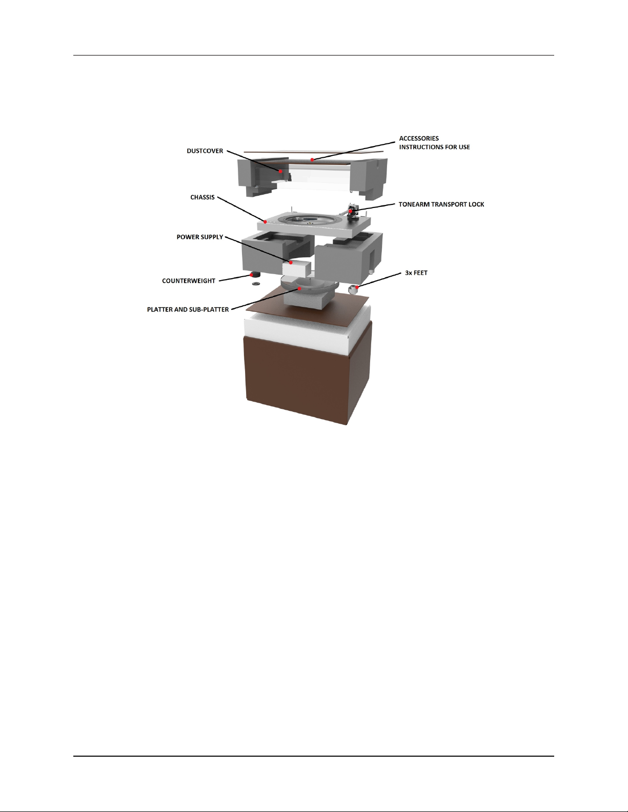
1.2 What’s in the box?
Getting started
1.3 Packaging
AVM packaging is carefully designed to protect your
component from damage during transport. We
highly recommend you keep the original packaging
in order to safely ship or otherwise transport your
turntable going forward.
The packaging materials were chosen to be environmentally friendly. In case you need discard the packaging material, please do your part to help protect
the environment and recycle properly.
ROTATION R 2.3 | 2 |
Page 7
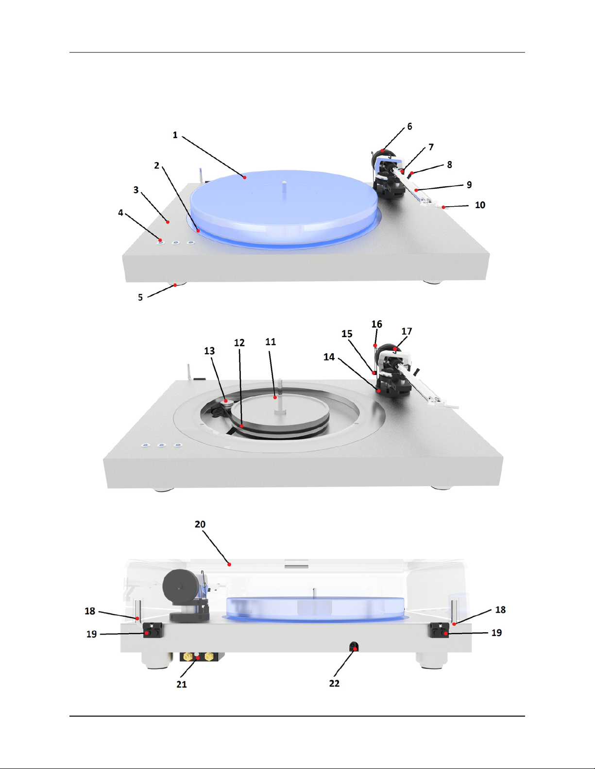
1.4 Control and operating elements
Getting started
ROTATION R 2.3 | 3 |
Page 8

Getting started
1. Acrylic platter
2. Acrylic lighting panel
3. Aluminium / MDF chassis
4. Speed control buttons
5. Damped adjustable feet
6. Tonearm counterweight
7. Tonearm rest and removable transport lock
8. Tonearm lift
9. Tonearm tube
10.Head shell with finger lift
11.Sub-platter
12.Drive belt
13.Motor with pulley
14.Tonearm flange
15.Anti-skating weight with thread
16.Anti-skating weight support
17.Anti-skating stub with adjustment scale
18.Dustcover hinge
19.Hinge fasteners
20.Dustcover
21.RCA tonearm output with earth connection
22.Power supply socket
ROTATION R 2.3 | 4 |
Page 9
1.5 Setup
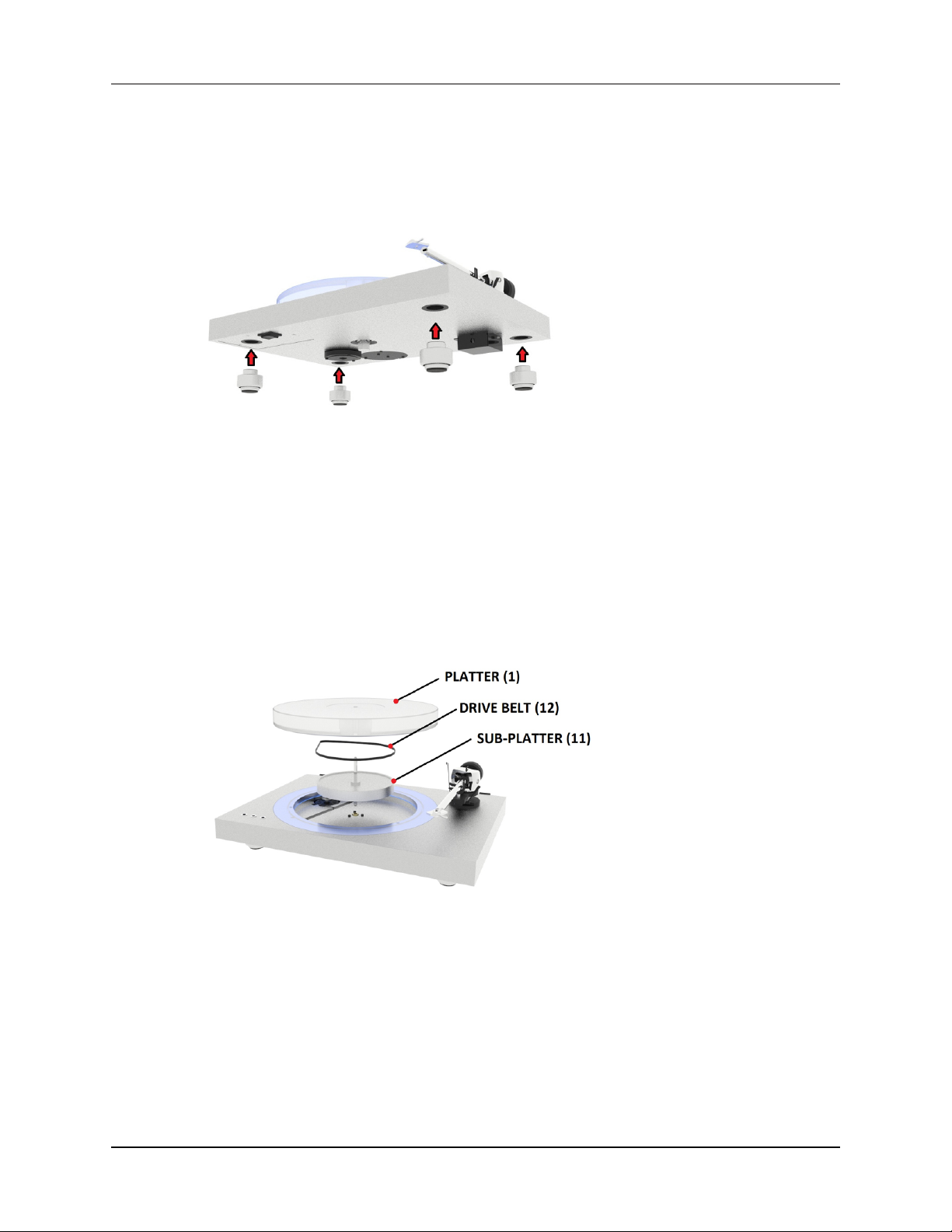
1.5.1 Feet assembly
Remove the three feet (5) from the grey foam insert
which holds the turntable chassis. Carefully lift the
turntable and screw the feet into the thread inserts
Getting started
on the bottom of the turntable. Balance the turntable by using a spirit level before next steps.
1.5.2 Platter, sub-platter and drive belt installation
Remove the protective cover from the sub-platter
(11). Install the sub-platter (11), drive belt (12) and
platter (1) as shown in the above illustration.
ROTATION R 2.3 | 5 |
Page 10

1.5.3 Speed control
To start the rotation of the platter for 33 r.p.m.,
press the left speed control button (4). To play 45
r.p.m., press the right-speed control button (4). To
stop the motor of the turntable, press the middle
speed control button and the turntable will switch to
standby mode.
Getting started
1.5.4 Light control
The turntable is equipped with blue LED diodes
under the platter controlled by a 3-way switch.
Left position – light LED back light
Middle position – no light
Right position – full LED back light
ROTATION R 2.3 | 6 |
Page 11

1.5.5 Output connection
Connect the tonearm cable provided with the accessories to the RCA tonearm output that is located at
the rear of the turntable, behind the tonearm. Con-
Getting started
nect a grounding cable on the earth connection
screw.
1.5.6 Tonearm setting
ROTATION R 2.3 | 7 |
Page 12

1.5.7 Cartridge installation
Install the cartridge into the aluminium head shell,
using the appropriate hardware included with your
cartridge.
Connect the cartridge as indicated below:
• White: Left channel L+
• Red: Right channel R+
• Green: Right channel R-
• Blue: Left channel L-
Getting started
If you are unfamiliar with cartridge setups, please
refer to your dealer.
1.5.8 Counterweight assembly
The counterweight has two separate parts:
ROTATION R 2.3 | 8 |
Page 13

The first part is the counterweight itself. The second part is an additional insert that enables optimal
balancing of heavier cartridges.
The counterweight without the additional insert can
balance cartridges from 5 to 9.5 g. The weight of the
counterweight itself is 120 g.
The counterweight with the additional insert can
balance cartridges from 9.5 to 18.5 g. The weight of
the counterweight with the additional insert is 158
g.
1.5.9 Vertical Tracking Force setting (VTF)
Getting started
Before setting the Vertical Tracking Force (VTF),
confirm the exact weight of your cartridge. Depending on your cartridge weight, determine whether to
use the counterweight with or without the additional
insert, in accordance with the specifications above.
Pushing carefully, turn the counterweight onto the
rear end of the counterweight support rod as shown
in the illustration above. Place a stylus pressure
gauge (not supplied) onto the platter. To set the
required VTF, lower the tonearm lift lever as indicated in the illustration and place the tip of the stylus on the pressure gauge.
ROTATION R 2.3 | 9 |
Page 14

As viewed from the head shell, turning the counterweight counterclockwise (moving it in closer toward
the tonearm) increases the VTF, turning clockwise
(away from the tonearm) reduces the VTF. Turn the
counterweight appropriately until the VTF shown on
the pressure gauge matches your cartridge’s recommended vertical tracking force specifications.
1.5.10 Vertical Tracking Angle setting (VTA)
Getting started
To set the Vertical Tracking Angle (VTA), first put a
record (VTF) on the platter. When the needle is lowered into the record groove, the tube of the tonearm
should be parallel to the surface of the record. If it
is not, loosen both hexagonal screws in the tonearm
base, just enough to allow vertical movement of the
arm pillar without force, and slide the arm up or
down until it is parallel.
Carefully and evenly re-tighten the hexagon screws
without applying excessive force (which may deform
the arm pillar).
ROTATION R 2.3 | 10 |
Page 15
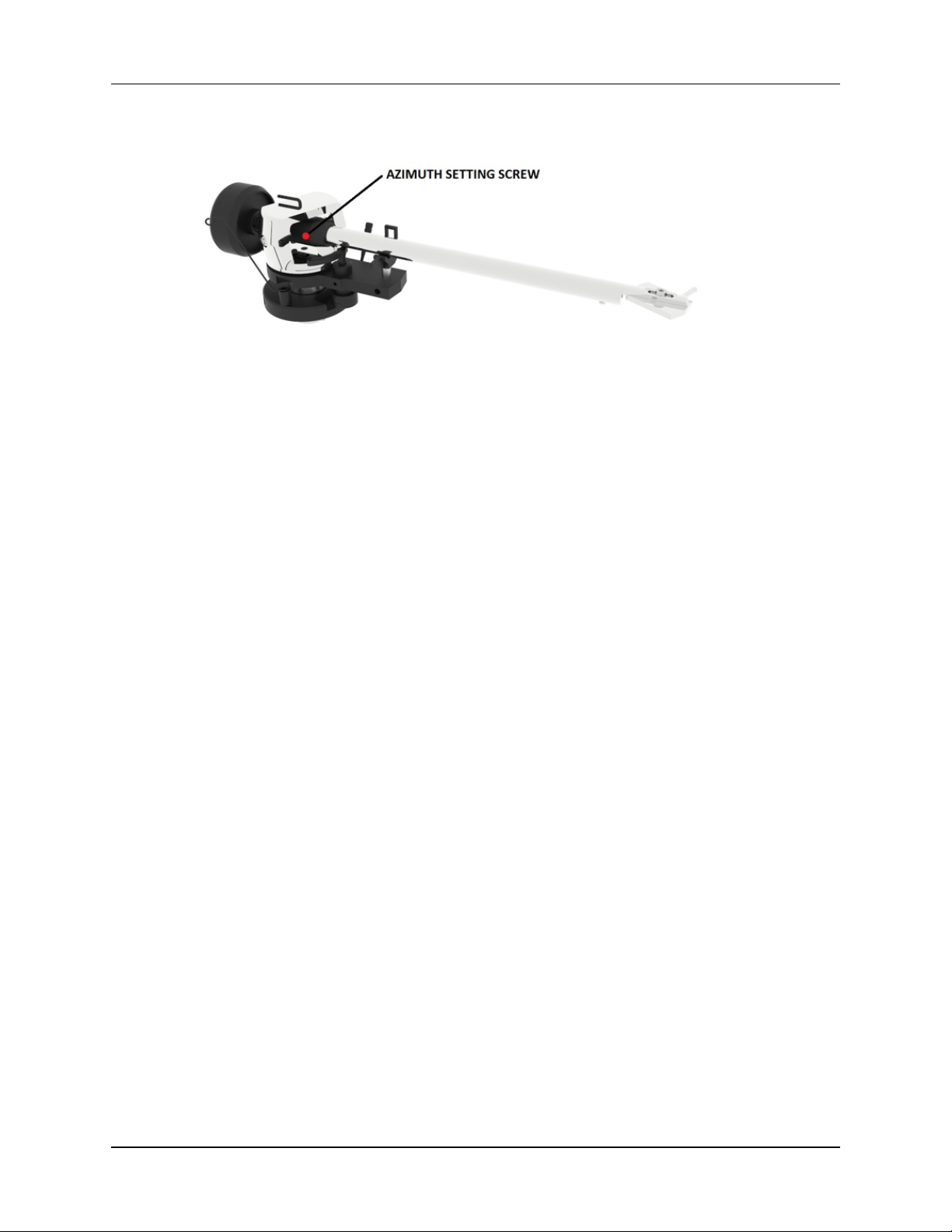
1.5.11 Azimuth setting
Getting started
CAUTION
Do not remove the
Azimuth setting
screw completely!
The cartridge needle must be perpendicular to the
record in order to trace the groove wall modulations
correctly.
The azimuth (angle) is precisely set by the factory.
In the event you need to modify this setting, please
follow the instructions below.
Loosen the small Azimuth setting screw using the
1.5 mm hexagonal allen key.
Loosen the screw just enough to be able to gently
rotate the arm tube and set the azimuth to the correct position. The correct position can be checked
from the front view, preferably with the needle
placed on a mirror placed on the platter. Once the
azimuth setting is correct, gently re-tighten the Azi-
muth setting screw.
ROTATION R 2.3 | 11 |
Page 16
Getting started
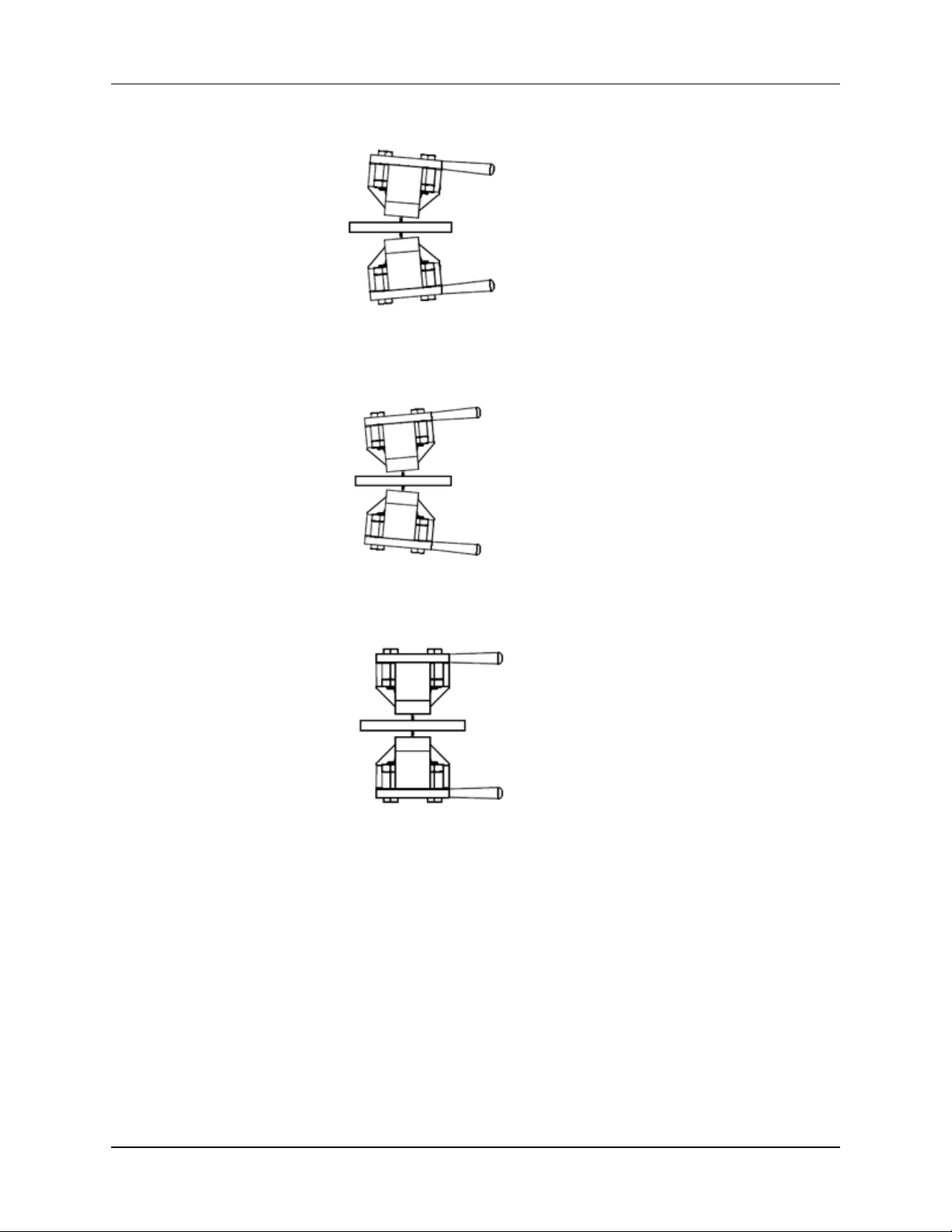
Examples of incorrect and correct azimuth setups:
FALSE: Too much left angle
FALSE: Too much right angle
CORRECT: 100% perpendicular to the record.
ROTATION R 2.3 | 12 |
Page 17
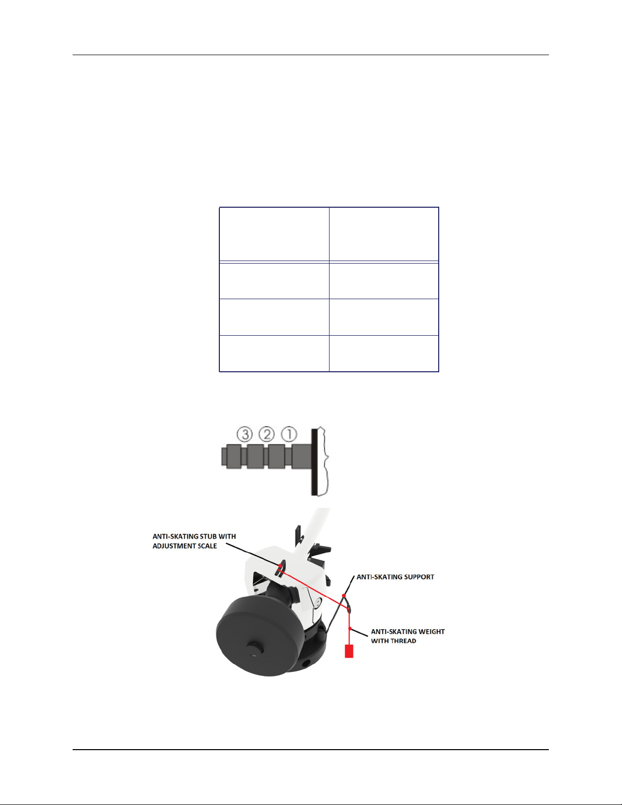
1.5.12 Anti-skating assembly and adjustment
Getting started
CAUTION
Be careful when handing the anti-skating
thread in order to avoid
damaging it.
Put the anti-skating thread over the anti-skating
adjustment scale and hang it over the anti-skating
support. The anti-skating force must be adjusted
corresponding to the down force as follows:
Tonearm
Downforce
Anti-Skating
Groove in the
stub (15)
10 - 14mN 1st groove from
bearing rings
15 - 19mN 2nd groove from
bearing rings
20mN and bigger
3rd
3rd groove from
bearing rings
ROTATION R 2.3 | 13 |
Page 18
CHAPTER
Appendix
2
2.1 Technical specifications
ROTATION R 2.3 | 14 |
Page 19

Appendix
Nominal speed 33/45 rpm, elec-
tronic speed
change, controlled by microprocessor
Speed variance 33rpm: ± < 0.15%,
45rpm: ± < 0.13%
Wow and flutter 33rpm: ± < 0.12%,
45rpm: ± < 0.10%
Signal to noise S/N Ratio: -70 dB
Downforce range 0 - 35 mN
0 - 3.5 grams
Supplied counterweight system
Counterweight
120 g without
additional insert
> for cartridges
5 – 9.5 g
Counterweight
with additional
insert 158 g
> for cartridges
9.5 – 18.5 g
Effective tone-
13.5 g
arm mass
Head-shell 0,5‘‘ (12,7mm)
standard
Mounting distance
212mm (platter –
tonearm base,
Linn standard
mount)
Effective tone-
230 mm
arm length
Overhang 18 mm
Power consumption
ROTATION R 2.3 | 15 |
5 W max/ 0.3W
standby
Page 20

Voltage Universal switch
mode power supply 15 V DC/
1.6 A (100-240 V
AC, 47 - 63Hz)
Appendix
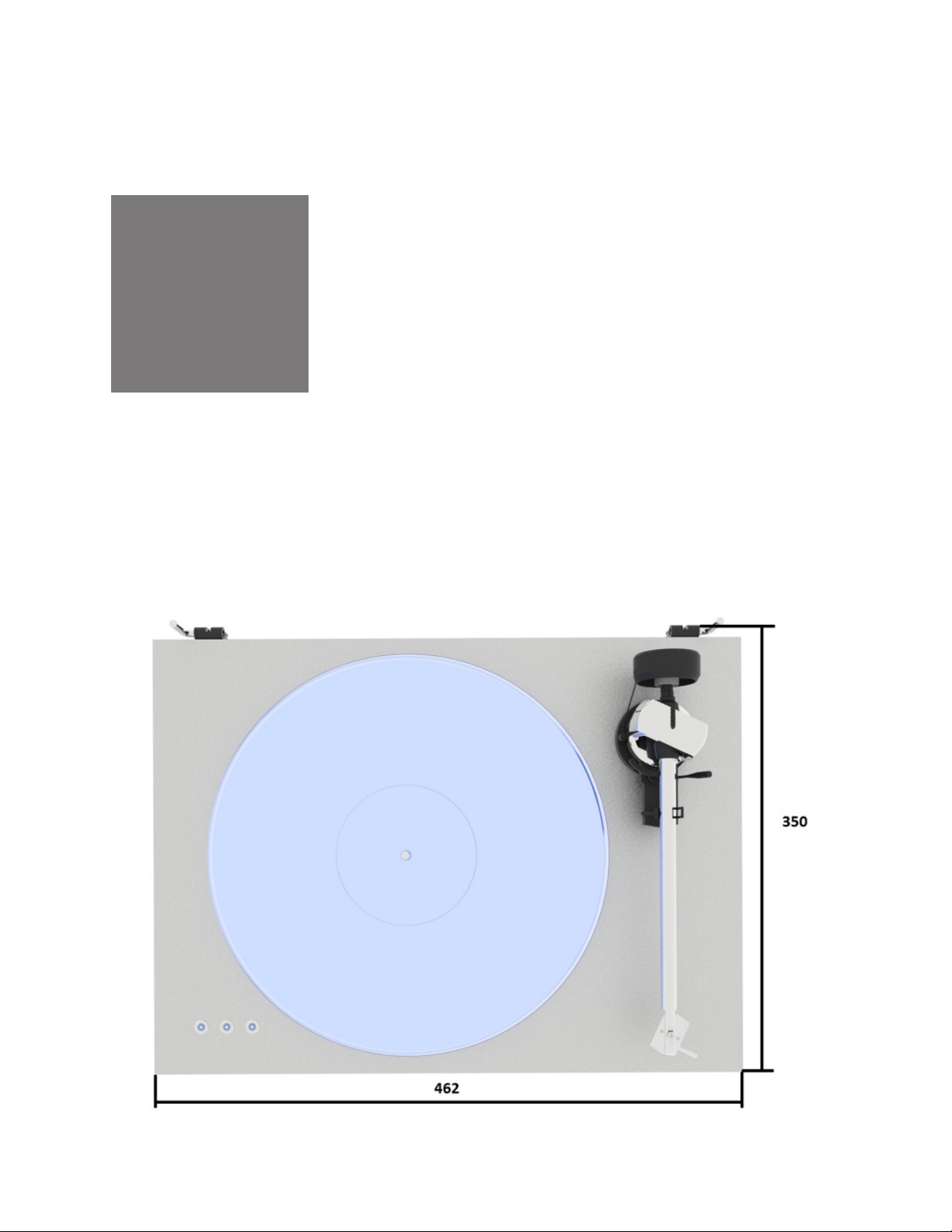
Dimensions (W x
H x D)
Weight (without
box)
Weight (with box) 9.5 kg
2.2 Accessories list
• Instructions for use
• Power supply 15V DC / 1.6 A
• Anti-skating weight
• Single adaptor
462 x 350 x
155mm
8.5 kg (turntable)
3.5 kg (platter)
• RCA output cable
• White cotton gloves
• Cloth
• Allen keys (1.5,mm, 2mm, 2.5mm)
• Counterweight
• Counterweight insert
ROTATION R 2.3 | 16 |
Page 21

2.3 Troubleshooting
The platter doesn’t turn although the unit is
switched on
• The unit is not connected to the mains power
supply (the building’s electrical system).
• No mains power is being delivered at the
socket.
• The drive belt is not fitted properly or has
slipped off.
No signal through one or both channels
Appendix
• No signal contact from the cartridge to the
internal tonearm wiring; or from that to the
arm lead; or from that to the phono box; or
between that and the amplifier. This could be
due to a faulty plug, broken wire or loose solder joint in the plug/socket connection.
• Phono input not selected at amplifier.
• Amplifier not switched on.
• Amplifier or speakers are defective or muted.
• No connection to the loudspeakers
Strong hum on phone input
• No ground connection from cartridge or arm
or arm cable to amplifier, or ground loop.
ROTATION R 2.3 | 17 |
Page 22

2.4 Service
Appendix
Distorted or inconsistent sound from one or both
channels:
• Turntable is connected to wrong input of
amplifier, or MM/MC switch is incorrectly set.
Needle or cantilever damaged. Wrong rpm;
drive belt overstretched or dirty; platter bearing needs lubrication or is dirty or damaged.
Should you encounter a problem that you are not
able to identify or alleviate despite the above information, please contact your dealer for further
advice. Only when the problem cannot be resolved
should the unit be sent to the responsible distributor in your country.
Guarantee repairs will only be effected if the unit is
returned in appropriate packaging. For this reason
we recommend keeping the original packaging.
Never return a turntable without making sure that is
it properly disassembled and correctly packaged in
the original packaging according to the supplied
diagram. Please: Remove the feet, counterweight,
platter, cartridge and belt and pack them separately.
Fit the cartridge protection cap. Insert the transport
lock for the tonearm prior to carefully packaging the
turntable.
ROTATION R 2.3 | 18 |
Page 23

2.5 Warranty
Appendix
The manufacturer accepts no responsibility for
damage caused by failing to adhere to these instructions for use and/or by transportation without the
original packaging. Modification or change to any
part of the product by unauthorized persons
releases the manufacturer from any liability over
and above the lawful rights of the customer.
The information above was correct at the time of
going to press. The manufacturer reserves the right
to make changes to the technical specifications
without prior notice as deemed necessary to uphold
the ongoing process of technical development.
This guide was produced by:
AVM Audio Video Manufaktur GmbH.
Copyright © 2018. All rights reserved.
August 24th 2018.
ROTATION R 2.3 | 19 |
 Loading...