

AVM PA 8.3 (Without Modules) Black, PA 8.3 (Without Modules) Silver, PA 8.3 (Without Modules) Cellini Chrome PA 8.3 Operating Instructions.pdf
Page 1

OVATION PA 8.3
Operating Instructions
Page 2

Declaration of conformity (for EC only)
We h erewith con firm, that the un it to whic h this manua l
belongs fulfills the EC rules necessar y to obtain the sign
the nec ess ar y me asu rem ent s we re t ake n wi th po sit ive
results.
AVM Audio Video Manufaktur Gm bH
Daimlerstraße 8
76316 Malsch
Germany
www.avm.audio
info@avm.audio
Page 3

1. Getting started
1.1 Wh at’s in the box? . .. 1
1.2 Cont rol and operating elements ... 2
2. Basic operation
2.1 First ope ra tion / se lf tes t ... 8
2.2 Selecting a sound source .. . 10
2.3 Volum e setti ng ... 10
2.4 An alog in puts ... 11
2.5 Dig ital In puts ... 12
2.6 Ph ono Input ... 14
2.7 Ph ono Settings .. . 15
2.8 FM-Tuner .. . 18
2.9 FM Tuner Set tings ... 20
2.10 Ad vanced FM Tune r Setti ngs ... 22
2.11 So und setti ngs .. . 2 3
2.12 Remote Con trol ... 2 7
3. Appendix
3.1 Per sonal Se tup ... 2 9
3.2 Res et (Facto ry Settings) . .. 33
3.3 Clea ning ... 34
3.4 Troublesho oting ... 3 4
3.5 Conditio ns of war ranty (EC only) ... 36
3.6 Spec ificat ions ... 37
Page 4

Page 5

CHAPTER
Getting started
1
1.1 What’s in the box?
• PA 8.3 Preamplifier
• Power cord ( in some count ries)
• RC 3 re mote c ontrol
After un packing , p lease check t he scope of deliv ery
to ensure that all pa rts h ave be en supplied and are
undama ged. In case the original packi ng ha s already
b een o p en ed , p l e as e co n t a c t y o u r lo c a l de a l e r.
Often, your deal er prepares your n ew device prior to
de liver y to adap t an d c hange t he co nf ig ura ti on to
your pe rsonal needs.
OVA TIO N P A 8. 3 | 1 |
Page 6
1.2 Control and operating elements
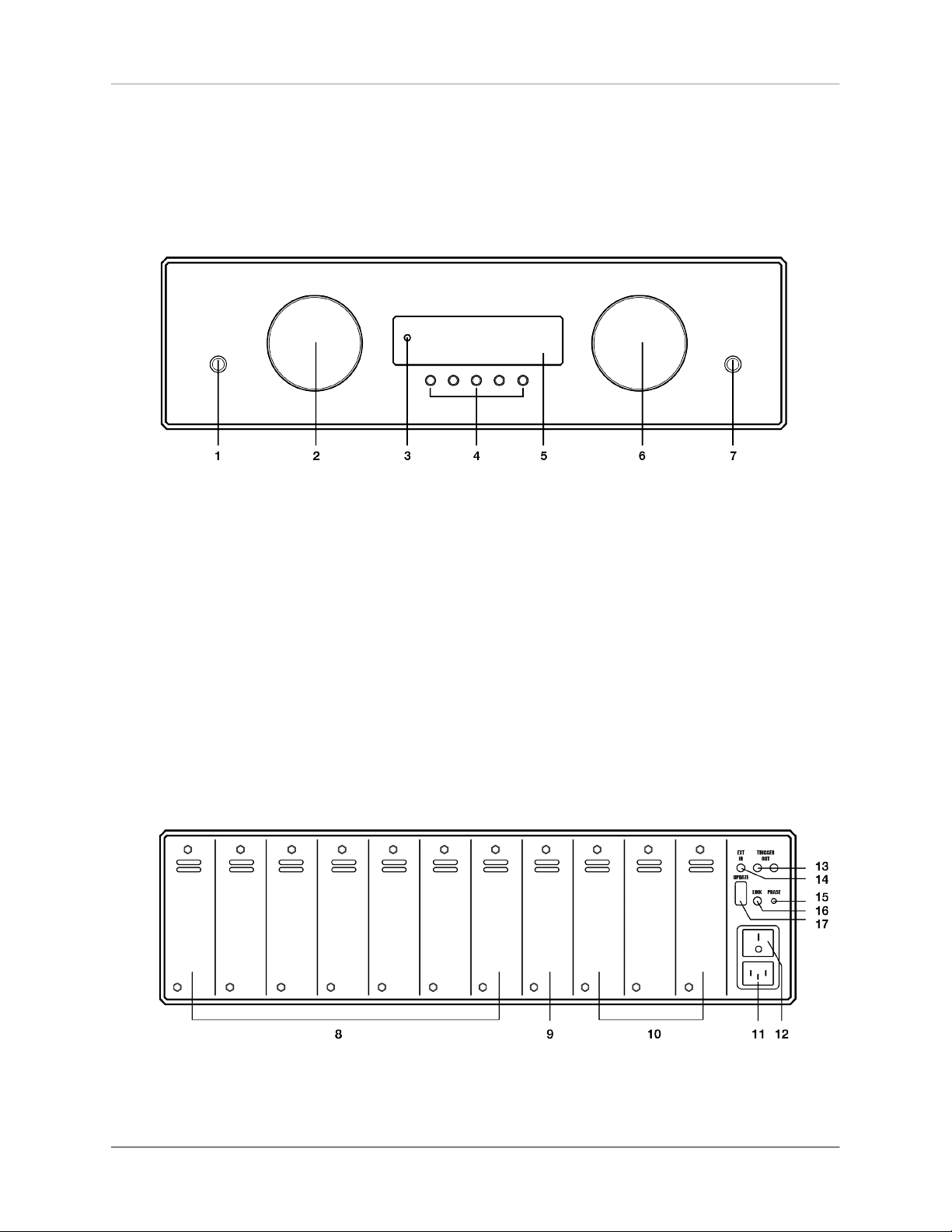
1.2.1 Front
1. Power button (on/of f)
Getting start ed
1.2.2 Back plate
2. Source selector
3. Contro l LED
4. Menu buttons
5. Displ ay
6. Vo lume k nob
7. Headph one ou tput ( 6,35mm )
OVA TIO N P A 8. 3 | 2 |
Page 7

Getting start ed
CA U T I ON
Pl ea se us e on l y Sl ot 8
t o i n s t a l l t h e I N P U T
T O N E c a r d ( 9 ) . T h e
Slot s 1-7 may b e all oca ted wit h all oth e r in p u t
c ar d s: I NP U T, T UN E R,
PH ON O M M / MC , DI GI TAL IN (8).
8. Slot 1-7 for all i nput c ards (e xcept INPUT TONE)
9. Slot 8 only for IN PUT TONE c ard
10. S lot 9-11 for all ou tput cards
11. M ains connecto r
12. M ains s witch
13. Trigger outpu ts (TR IGGER OUT)
14. I nput for exte rnal IR receiver (E XT IR)
15. P hase LED
16. Link-Port
17. C onfigu ration p ort (Firmwa re)
1.2.3 Pin assig nment: XLR
XLR in put (l eft)
XLR ou tput (right)
1. Ground (GND)
2. Non-in vert ing in put/out put PO S (+)
3. Inver ting input/o utput NEG (- )
OVA TIO N P A 8. 3 | 3 |
Page 8
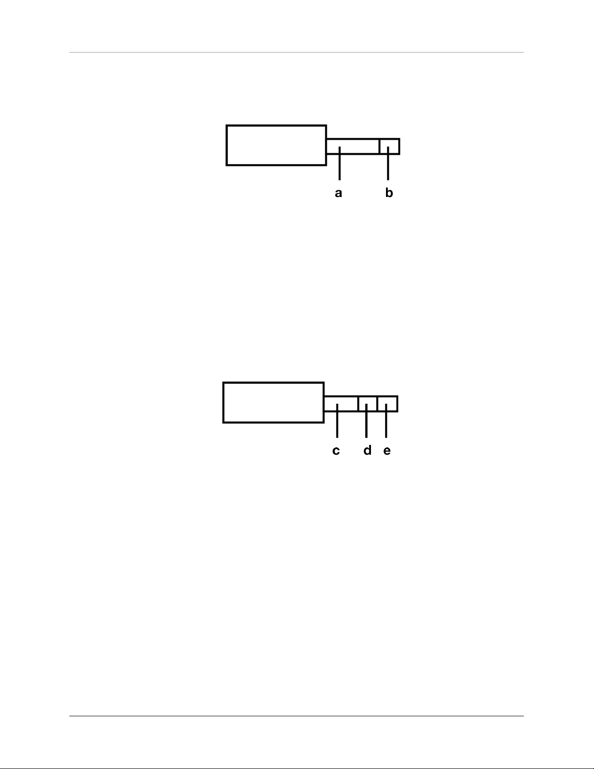
1.2.4 Pin assig nment: Trigger outputs
Pin as signment of the 3 ,5mm j ack ou tput
for e xternal trig ger si gnals( 13)
a) Ground (GND)
b) Trig ger si gnal (+5V)
Getting start ed
1.2.5 Pin assig nment: Input f or external IR receiver
Pin as sig nm en t of 3, 5m m s ter eo jack inp ut fo r
extern al IR receiver (14 )
c) Groun d (GND )
d) IR signal
e) +5V
OVA TIO N P A 8. 3 | 4 |
Page 9

1.2.6 Assembly of input and output cards
Getting start ed
CA U T I ON
P l ea se ma ke s ur e th e
ma in s pl ug is rem ove d
b e f o r e y o u o p e n t h e
uni t . Pl u g-i n c ard s m ay
n e v e r b e i n s t a l le d o r
re m ove d wh i le th e un i t
is po w ere d on . In case
o f a n y d o u b t, p l e a s e
con su l t yo ur lo ca l d ea l e r t o a s si st y ou w it h
t h e as s em b l y of i n ou t
and output c ar ds.
NOTE
Ke e p th e un i t sw i tc hed
o f f u n t i l a l l a u d i o
conn ec t i on s are made.
At the back o f the PA 8.3, there is a to tal of 11 slo ts
wh ich m ay b e al lo ca t ed w i th o pti on a ll y av ai l abl e
in p u t an d o u tp u t c a rd s ( s l ot - i n mo d ule s ). T h ese
slots are co unted from the left to the right (see secti on" Ba ck pl ate " on p ag e 2) . E xist in g plu g- in c ard s
can be in almost any order. Unu sed slots come with
a bla nking plate c overed.
The nature of all plug-in cards is ident ical (width
of t he c over pla te, pos it ion of the plug ). Nevertheless, to ensu re correct ope ration of the PA 8.3, some
placement ru les mu st be observed:
1. Input cards c an be place d in an y orde r to th e slots 1-7 (8 ).
2. The I NPUT TONE ca rd wit h integrated sound control may e xclusively be instal led i n slot 8 (9).
3. Outpu t cards are in stalle d in sl ots 9 -11 (10).
Pl ea se n o te : Eac h ti m e t he de v ic e is pow er ed o n
with the power switch on the rear side (12), the unit
goes through a hardw are test and verifies the confi gur at io n and fu ncti onal ity of the in pu t an d o ut put
cards used. The current statu s o d th e t est is shown
on the display (5). If the mod ule is placed i ncorrec tly or in th e wrong posit ion (e .g. inp ut module i n the
posit ion of an output module), the ha rdware test wi ll
be abor ted and an error message is displ ay ed.
OVA TIO N P A 8. 3 | 5 |
Page 10

1.2.7 Connection of sound sou rces
An a lo g a n d di gi t al sou r ce s a re c o nn e cte d to the
inputs of the in stalle d input c ards of th e PA 8.3. The
left channel is co nnected to the whit e ma rked RCA
in put , th e r igh t one ch an ne l a t th e re d m ar ked. At
the XLR input s, the upp er po rt is intended fo r the left
channel (L), the l ower one for the right c hanne l (R).
1.2.8 Connection of power amplifiers
Getting start ed
NOTE
M a k e s u r e w h e n
co n ne ct i ng X LR ca b le s
t h a t co r re ct wi r i ng of
t h e X L R p l u g i s u s e d
(s e e sec tio n " P in as si gn-
ment: XLR" o n p a g e 3).
Use s ui ta bl e c ab le s to conn ect yo ur po we r a mp li fi e r ( s) to th e c o nne c to r s o f t he in s tal l ed ou t pu t
cards in the slots 9- 11 (se e se ct io n" Ba ck p la te" on
page 2).
The left ch anne l transition s to the whit e marked
RCA, the ri ght ch annel to the r ed mar ked RCA .
For th e XLR outpu ts, the upp er p ort is fo r the left
channel (L), the l ower co nnecti on for the ri ght channel (R ).
1.2.9 Rem ote activation of power amplifiers
1.2.9.1 Remote ac ti va t ion of powe r am plifiers wi t h
analog tr igg er input
If your amplifier is e quipped with a trigge r inpu t, the
PA 8. 3 can re motely t urn it on . To do th is, con nect
on e of the t wo t ri gg e r out pu ts of t he PA 8. 3 (1 3)
OVA TIO N P A 8. 3 | 6 |
Page 11

Getting start ed
with a trigger in put o f you r amp lif ier. For a cor rect
p i n as s i g n m e nt , p l e a s e re f e r s ec ti o n , s e e se ction"Pin a ssignm en t: Trig g er out p uts" on page 4.
1.2.9.2 Remote ac ti va t ion of lates t generation AVM
amplifi er s
If you have an AVM am pli fier of th e l ate st g en era ti on co nn ec ted (EV OLU TI ON MA 3 .2 , S A 3.2 , O VATI ON MA 6/ 8 . 2 , SA 6/ 8 . 2 ) , i t wi l l au t o m a t i c a l l y
turne d on, p rov ided the respective mod e i s activate d
at yo ur AVM am pl ifi er. A co nne ction of a s epa rate
trigge r cable (see section" Rem o te ac ti va tion of powe r
ampli fi e rs with analo g tr i g ger i nput" o n page 6) is n ot
require d in t his case.
1.2.10 Co nne ction of headphones
HINWEI S
Pl ea s e note that al l outp u t s i g n a ls ( 1 0 ) a r e
m u t ed as lo ng a s t h e
headp ho ne output ( 7) is
conn ec t ed .
Throu gh t he he adphone ou tput o n t he fro nt of the
unit (7), he adpho nes wi th a 6,3 5 mm ja ck plug may
be connected. The volume of th e headp hone output
signa l is reg ulated with the vo lume control (6).
OVA TIO N P A 8. 3 | 7 |
Page 12

KAPITEL
Basic operation
2
2.1 First operation / self test
CA U T I ON
If the device is too cold,
condensation water ca n
f o rm i ns id e t h e u n i t .
T h is m a y d a m ag e t h e
unit if i t i s s witc h ed on
t o o e a r l y . T h e r e fo r e ,
a l l o w t h e P A 8 . 3 t o
s ta nd in th e l i s te ni n g
r o om f or a t l e as t on e
hour b e fo r e switching it
on so tha t it ca n ad a pt
to the curren t room tem pe ratu re.
First , p ress the po wer switch on the rear panel (12)
and a hardware test will be p erfor med . The device
ch ec k s t he c on fi guration an d fu nctio na li ty of t he
input and ou tput card s us ed. Th e cu rrent st atus of
th e h ard wa re te st is sh ow n i n t he displ ay (5 ). If a
module is n ot i nser ted prope rly or in the wr ong position (f or exam ple, input mod ule in the pos ition o f an
output modu le), the hardware test i s abor ted and a
co rr es po nd i ng er ro r mes sa ge a pp ea r s. Upo n su ccessfu l comple tion of th e hardware test, the device
enter s stan dby mod e.
The on / off button (1) allows you to s witc h bet-
ween operati on and standby m ode. In s tandby mod e,
the disp lay is dark and the cont rol LED (3) is lit. As
soon as the dev ice i s in o pera tion, th e contro l LED
goes ou t and the d isplay is activated.
OVA TIO N P A 8. 3 | 8 |
Page 13

Basic operation
Pleas e n ote: Th e de vice is no t entirel y di sconne cted
in stan dby mo de. To disco nn ect compl etely, pr ess
t he m ains sw i t c h on th e re a r p a n e l (1 2 ) or d i s conn ect th e powe r cable from the m ains c onnector
(11).
2.1.0.1 Phase LE D
A glow ing ph ase LE D on th e bac k (15) indicates an
in c or re c t ph as e. T her ef o re , mak e su r e the pha se
LED does not lig ht up af ter swit ching o n the de vice
for the first time . Otherwise cha nge the phase posi ti o n, e .g . b y tur n in g t he m ai n s plug t o th e p o wer
socket.
2.1.0.2 Tu b e warm-up
I f an o p t i o na l T U B E O U T c a r d i s in s ta l le d , t h e
switc h-on proces s will take about 30 secon ds due to
th e r equired tu be warm -u p tim e. Ple as e wa it un ti l
the entire display wa iting for tub e warmup changes
comp let ely f rom l ower cas e to u ppercase and the n
goes ou t. The device is now ready for us e.
Witho ut a TUBE O UT c ard installed, the switch-on
pr oce s s ta ke s a pp r ox . f iv e s e co n ds . The d i sp l ay
shows a corr espondi ng countdow n duri ng thi s time .
OVA TIO N P A 8. 3 | 9 |
Page 14

2.2 Selecting a sound source
Basic operation
NOTE
I n pu t n a m e s of so u nd
sourc es can be a d j us t e d
as de s ire d vi a t h e pe r-
so n al setu p menu (se e
sec t ion " Pers on al Set up "
on pag e 29).
To sele ct a sound so urce, turn the so urce select or
(2). Th e sele cted program source is sh own in large
lette rs on the display (5) - e.g. RCA, XL R, USB , OPTO
or COA X . A n e xce p t io n i s t h e TU NE R i n p ut ca rd :
Here, e.g. the freq uenc y RDS nam e of t he cu rren tly
selected st ation is di splayed in large letters instea d
(see section "S e t R DS d ispl a y" on page 20).
2.3 Volume setting
To adjus t the volu me, u se th e right-hand rotary cont ro l (6 ) . T he cu r re nt vo l u m e va l u e is di s p l a y e d
numeri cally (0 to 99.5 dB) in large letter s in the display ( 5).
The s tep size of th e volume change depe nds o n
th e r ota t io n s p ee d . S low r o ta t i on cau s es a l e ve l
change in steps of 0.5 dB, fast turn ing cha nges the
volume in 2 dB steps.
Plea se not e: If an o ptio nal digita l inpu t is se lect ed
and there is no va lid dig ital signal , the dis play wil l
show N O DIG S IGNAL instead of a volum e value. I n
this state, adjusting t he volum e is n ot po ssible .
OVA TIO N P A 8. 3 | 10 |
Page 15
2.4 Analog inputs
Basic operation
NOTE
To us e a n a nalog in p u t,
it is n ecessary to install
an op ti o na l in pu t c a rd
(INPUT o r INPUT TONE )
(see section "As sembly o f
i np ut an d o ut pu t c ar ds "
on pag e 5).
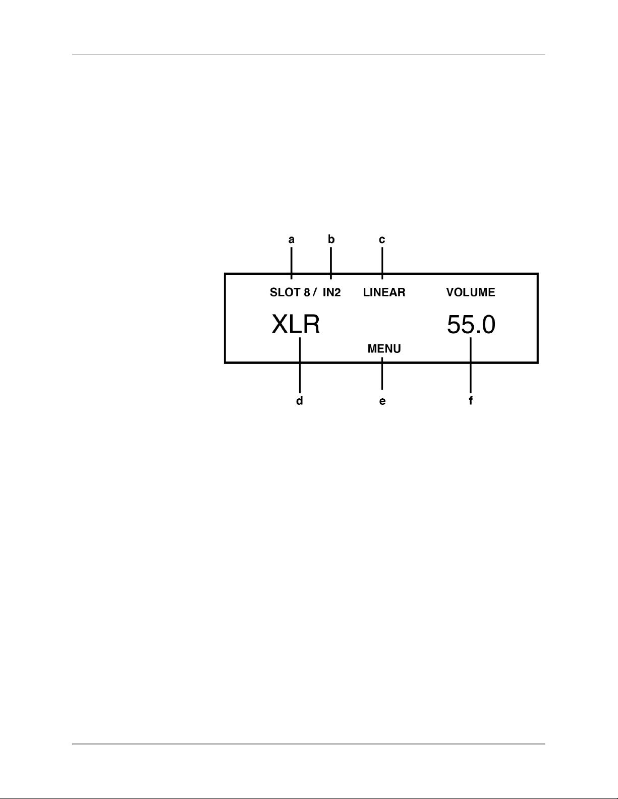
To se l e ct an a va i la b le an al o g ue i n put , p re s s t he
so ur ce sel ec to r swi tc h (2) un til th e de sire d inp ut
na me is sh ow n on th e disp la y i n l ar ge le tt er s (d ).
Addi tional sound setti ngs ar e available by p ressi ng
the MENU (e) button (se e section "S ound set ti ng s " on
page 23).
a) SLOT: Indicates the s elect ed slot of an
input card (s lot 1- 8).
b) IN: Numeric d is play of the sel ected input o n a
card, e .g. 1 for RCA, 2 for XLR. T h e nam e of the
selected inpu t is shown i n large letters below.
c) LINEAR : Sound cont rol is deactivate d .
TO N E: Sound co n tro l is activated .
(see sectio n "So und settin gs" on page 23).).
(
d) Na me of the sele c ted input. This c an be
adjusted as nee ded (see sec ti on "Def ine i nput
names" on p age 31 ).
e) MENU button to sel ec t the sound settings
secti on "S oun d se ttin g s
f) VOLUME: Volume i n di cator (see sectio n "Vo l-
ume sett i ng" on pa ge 10 ).
" on page 23).
(see
OVA TIO N P A 8. 3 | 11 |
Page 16

2.5 Digital Inputs
Basic operation
NOTE
To us e a di gi t a l i n put ,
t h e i n s t a l la ti o n of an
o p t i o n a l i n p u t c a r d
(DIGITAL I N ) is re qu ir ed
(see section "As sembly o f
i np ut an d o ut pu t c ar ds "
on pag e 5).
To se lect an avai labl e dig ital i nput, turn the so urce
selec tor (2) un til th e de si red in put na me is sh own
on the display in large lett ers (h) . Add itional sound
setting s a re av ailable by pr essin g th e M ENU (l) button (s ee se ction "Soun d set tin gs" on page 23).
g) SLOT: Indic at es the sele ct ed slot of a n in p ut
card (slot 1- 8) .
h) IN: Numer ic display of the se lected inpu t o n a
card, e.g. 1 for USB, 2 for OPTO, 3 for C OAX 1,
4 for COAX 2 . The na me of t he selec t ed input is
shown in ca pi ta l letters b elo w and can b e
adjusted as re q uired (see s ec t io n "Defin e input
names" on p age 31 ).
i) LINEAR : Sound control i s deactivated.
TO N E: Sound co n tro l is activated .
j) VOLUME: Volum e indicator (see s e ction "Vol-
ume sett i ng" on pa ge 10 ).
k) CO N V Menu buttons fo r selecting t he sample
ra te and the fil ter setting (m) - see secti on
"Sampl erate and Filter se ttings" on page 1 3.
OVA TIO N P A 8. 3 | 12 |
Page 17

l) MENU but to n to select the s ou nd settings ( see
section "S ou nd set tings" on p age 23 )
PLEASE NOTE: MENU o nly displayed i f a valid
signal is ap plie d to the se le c ted digital i n pu t.
m) Di splay of the c urre nt sample rate ( NATI VE or
CNV) and th e filter set ti n g (FAST or SLOW) see section "Samplerate a nd Filter set t ings" on
page 13.
2.5.1 Sample rate and Filter settings
Basic operation
NOTE
F o r U SB , o n l y th e
two options NATIV E
FA S T a nd N AT I V E
SLO W are availab le.
By pressing the tw o menu butto ns CO NV (k) o nce or
se ve ra l ti me s, y ou c an c h oo se b et wee n av ai lab le
sa m pl e rat e s an d f i lt e r sett i ng s f or the sele ct e d
digit al in put. The sett ing is s aved for each indi vidual
input until the ne xt man ual ch ange.
N ATI V E i n d ic a t es t h a t t h e sa m pl e r a t e of the
applie d signal is pro cessed direc tly. CNV stands for
'c onve rsi on' a nd m eans that it up sam ples or do wnsampl es to th e desired an d displ ayed s ample ra te.
The fil ter settings FAST and SLOW can be s elec-
ted acc ording to your ton al prefer ences . Depen ding
on the s ignal pl ayed b ac k, di ffere nt fi lter setti ng s
can pr oduce the mo st prefera ble so und.
Technically speaking, FAST me ans s teep filtering
at the band end with a flat a mplitude response, but
wi th st ron g p ha se rot at ion. By co nt rast, S LO W filters le ss st eeply an d already has a small am plitude
dr op b ef ore th e en d of t he f re q ue nc y ba nd , bu t a
lo we r p ha se sh if t. The s el ect e d fil ter s et ti ng on ly
applie s to the current inp ut and remains stor ed even
af te r th e d ev i ce h as be e n swi tc he d of f . It c an be
changed at a ny time by pres sin g the m enu buttons
CONV ( k) ag ain.
OVA TIO N P A 8. 3 | 13 |
Page 18
2.6 Phono Input
Basic operation
NOTE
To u se a phono in pu t , an
o p t i o n a ll y a v a i l b a l e
p h o n o i n p u t c a r d
( P H O N O MM / MC ) i s
r e qu i r e d ( s e e s e ct i o n
" A ss e m bl y o f i n p u t a n d
outp ut ca rd s" on page 5).
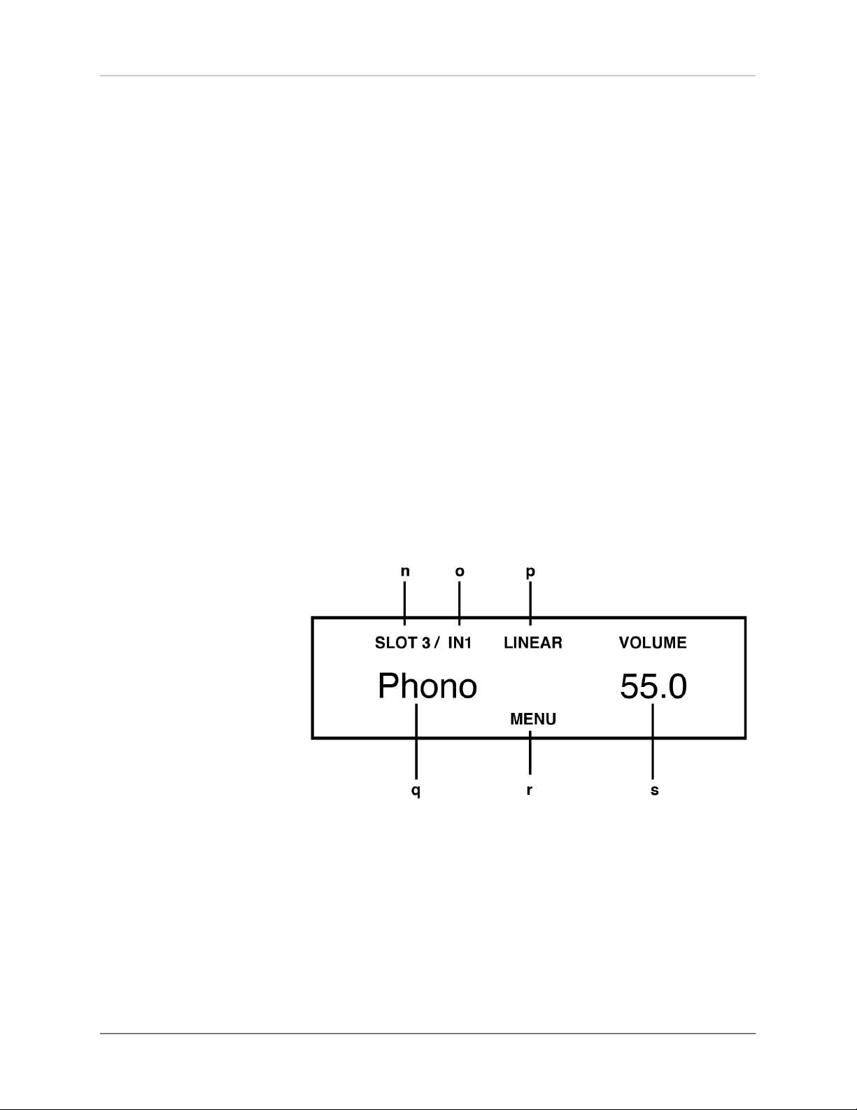
To sel ect a n avai labl e pho no input, t urn t he so urce
selec tor (2) un til th e de si red in put na me is sh own
on the disp la y in l arge l et te rs (q ). Se tt ing o pti on s
(M M / M C, pho n o ga in , s u bs o ni c f il t e r, e t c. ) a re
availab le by pressin g the MENU button (see sect ion
"Pho no Set t in gs " on page 15 ). For more o ptio ns, s ee
secti on "S oun d se ttin g s" o n page 23.
All se ttings made f or the p hono c ard ta ke effect
im m edia t el y. T hi s way, di ff e re n t o p ti o n s may be
compar ed in re al tim e while a re cord is playin g.
n) SLOT: Indicates the selected slot of an
input card (s lot 1- 8).
o) I N: Numeric d is play of the sel e cted input on a
card (in cas e of the phono c ar d , only one i np ut
OVA TIO N P A 8. 3 | 14 |
Page 19

Basic operation
is available). The name of th e s el e cted input is
shown in la rg e letters below.
p) LI NEAR: Sound co ntrol is deac ti vat ed.
TO N E: Sound co n tro l is activated .
q) N a me of the sele c te d input. This c an be
adjusted as nee ded (see sec ti on "Def ine i nput
names" on p age 31 ).
r) MENU But ton t o a ccess the pho n o settings
(see sect i on "Ph ono Sett i ngs " on pa ge 1 5) and
sound sett ing s
on page 23
s) VOLUME: Vo lum e indicator (see se ction "Vol-
ume sett i ng" on pa ge 10 ).
(see sectio n "So und se tti ngs "
).
2.7 Phono Settings
A shor t pres s on th e MEN U button takes y ou to the
Pho no Se ttings menu. T he la bel o f th e sam e men u
key n ow change s to EXIT . Press the button again to
ex it t he m en u and r et ur n to the nor ma l ope ra ti ng
state.
Ind ivi dual menu it ems may b e se lect ed w ith the
<ITEM> keys. T he selected menu item is always displ a y ed in t h e u p p er ar ea of t h e d i sp l a y. U s e th e
<VALU E> keys to cha ng e th e valu e of th e s ele cte d
menu item . The settings made take effect imme diately. Th is way, you m ay immed iately c ontrol respective adjustm ents w hile a record is pla ying.
Pl e ase not e : B e si d e s the ph ono s e t ti n gs ex plained below, yo u will f ind fur ther s ound settings in
t he sa m e m e n u ( s e e s e c t i on "S o u n d s e tt in gs " on
page 23).
OVA TIO N P A 8. 3 | 15 |
Page 20

2.7.1 Set phono mode (M M/MC)
De p en d i n g on th e co n s t r u c t i o n pr i n c i p l e o f th e
pic ku p sy ste m, u se MM f or el ectrom agn et ic t ransdu c ers (MM = M o vi n g M agn e t) , o r s elec t M C f or
el e ctr ody nam i c tra n sd u c er s ( MC = Mov i ng C o il) .
Please refer to the corresponding documenta tion of
yo u r pi c ku p s y st e m t o fi nd ou t wh e th e r it wo r k s
accordi ng to the MM or MC princ iple.
Pleas e note: In case the output level of yo ur MC
system is hi gh enough, the MM setti ng can also be
us ed . For fur t he r inf or ma tio n, p le as e ref er to t he
operatin g ins tructions of your t urntab le or pickup .
Basic operation
2.7.2 Set phono gain
Use the set phon o ga in function to adjust the gain to
mat ch th e picku p y ou a re u sin g. De pen din g o n th e
output vol tage o f the syste m, a setting between 43
dB and 52 dB (with MM set ting) or 63 dB and 72 dB
(MC se tting) may be selec ted.
Pl e as e no te: E ve n w it h a ' wr ong ' se tt i ng , yo u r
pho no ca rd will not be da maged . If the gai n i s too
high , how ever, a n aud ible overload by the pickup is
possible.Pl ease make su re to reduce the gain in this
case.
2.7.3 Set subsonic filter
The fu nctio n set subson ic fil ter offe rs you a n opti onal subsonic filter to reduc e audible rum ble no ise in
OVA TIO N P A 8. 3 | 16 |
Page 21

the l owest bass range. Activat ion is especially adv isable for corrugated records or un favorable ins talla tions of th e turntable ( struct ure-bor ne soun d).
2.7.4 Set MM capacitance
For a perfect sou nd expe rience, the set c apacit ance
f e a tu r e p r o vi d e s t h e a b i li ty t o c u st om i z e t he
connec tion c apacity for MM sy stems.
Ple as e n ot e: T he tot al ca pacit y c on si sts of th e
d is p l a yed va l u e p l u s t h e c a p a c i ty of th e su p pl y
cable (rule of thum b: 100pF per mete r). Fo r optimum
capaci ty re fe r to the instr uctions of your turntable /
Basic operation
pickup.
2.7.5 Set MC resistance
NOTE
Th e me nu i t em i s on l y
di sp la ye d if t he p h o n o
mode is set t o ‘MC ’ (s ee
section "S et p hono mod e
(MM/M C) " on page 1 6) .
Th e s et M C resi st a nc e f u nc ti o n ad j us t s th e l oa d
impeda nce fo r MC systems. Please refer to the instruc tion s of you r tu rntable / pic kup for inst ruc tion s
on the optimum loa d impedance.
OVA TIO N P A 8. 3 | 17 |
Page 22

2.8 FM-Tuner
Basic operation
NOTE
To use the F M tun er it is
ne c es s ar y to i ns t all an
o p t i o n a l i n p u t c a r d
( T U NE R ) ( s ee se c ti on
" A ss e m bl y o f i n p u t a n d
outp ut ca rd s" on page 5).
After selecti ng the FM Tuner wit h the sourc e selector (2), yo u may operate all funct ions with the menu
b u t t o n s ( 4 ) b e l o w t h e d i s p l ay . Fu r th er s e t t in g
opt ions (R DS , se arc h m ode, e tc. ) a re av ail ab le vi a
the FM Tuner Settin gs me nu (see s ection "FM Tune r
Se tti ngs " o n pag e 2 0) a nd t he men u A d van c ed FM
Tu ner S ettin gs (se e sect ion " Advanc ed FM Tun er Set-
tings " on page 22).
t) STAT: Displays a s ta ti o n memory l oc ation (see
section "S tor i n g new s tati ons" on pa ge 1 9) .
u) Display of s t ation frequency or RDS name ( see
section "S et RDS d isplay" o n page 20).
v) LOCKED indic at es an identif ie d station. W hen
the RDS N AME is activ at ed, the stat io n fre quency is d isplayed here inst ead (see sect ion
"Set R DS d i splay" on p a ge 20 ).
w) In di cates wh e ther a station is being received in
MONO or S T E R EO.
x) S TAT: Menu bu ttons for recall ing stored sta-
tions (see s e ction "R ecalling s tored st ations " on
page 20).
OVA TIO N P A 8. 3 | 18 |
Page 23

2.8.1 Tuning
Basic operation
y) MENU But to n to access FM Tu ner Sett in gs (see
section "F M Tun er S ettin g s" on pa ge 20 ) a nd
Advanced F M Tuner Sett i ng s (see section
"Advanced FM Tu ner S etti n gs" on p a ge 22 ).
z) VOLU M E: Volume indic ator (see section " Vo l-
ume sett i ng" on pa ge 10 ).
aa) AUT / MAN: B u ttons for autom at ic or manual
tuning (see se ction "Tuning" on page 19 ).
Depen ding on whe ther the sca n mode has bee n set
to m anual or automatic (s ee sectio n " Set scan mode"
on page 2 1), the right butto ns below the display are
la b el e d A UT or MA N. Whe n s et to A UT , p re s sin g
these bu ttons enables an autom ated sea rch proces s
to ide ntify the next higher or lo wer station (in terms
of fr eq uen cy ). Wh en se t to M AN , a ma nu al bu tt on
pre ss ch an ges the re cei ve freque ncy by 50 k Hz . I f
pre sse d f or a lon ge r ti me, the frequenc y will au tomatica lly m ove up or down in 5 0 Hz in cremen ts.
2.8.2 Storing new stations
You h ave the optio n to save a curren tly sele cted statio n , to m ove an a lre ad y s to red statio n, to sa ve it
wi t h c h an ged s et tin gs or t o dele te i t. T he d ev i ce
al s o off er s a co n ve n ie nt autos t or e f unc ti o n (s ee
secti on "S et s can m ode " on pa ge 21).
OVA TIO N P A 8. 3 | 19 |
Page 24

2.8.3 Recall ing stored stations
Use t he tw o bu tton s STAT (e) to se lect sto red st atio ns . Sh or t ta p s wit che s to the next h igh er / ne xt
lo wer m em o ry loc a ti on . Kee p one of the b u tt ons
presse d to switch to automat ically th e ne xt stati on.
The nu mber of the currently selec ted memory location is sho wn in the upper left corne r of the displ ay
(see t in t he fig ure abov e).
2.9 FM Tuner Settings
Basic operation
NOTE
Th e FM Tu n e r Sett in g s
menu i s onl y available if
a TU N E R i n p u t car d is
i n s t a l l ed (s ee s e c t i on
" A ss e m bl y o f i n p u t a n d
output ca rd s" on page 5 )
and selected as t h e curren t s o un d source.
A shor t pres s on th e MEN U button takes y ou to the
FM Tuner Se ttings men u. Th e key label of t he same
me nu ke y no w cha ng es t o EXIT . Pr es s the b ut to n
again to exit t he menu and retur n to the normal operating st ate. Ind ivi dual men u it ems c an be select ed
wi th t he < ITE M > ke ys . Th e s el e ct ed m en u it e m is
alway s d is playe d i n t he up pe r a rea of th e di sp lay.
Use t he < VAL UE > k ey s t o ch an ge t he va lu e of t he
selected men u item.
Ple ase not e: A fte r calling u p th e FM Tuner Settings op tions explaine d b elow, you w ill find additio-
nal so und se tti ngs i n th e s ame me nu ( se e s ect ion
"Sou n d s ett i ngs" on page 23).
2.9.1 Set RD S display
RDS stan ds for 'Ra dio D ata S yste m' and al lows the
tran sm ission and in dic ation o f a ddi ti ona l in forma tion of the selecte d radi o st ation on the display (5) .
OVA TIO N P A 8. 3 | 20 |
Page 25

The set RDS dis play funct ion allow s you to sel ect a
frequen cy (F REQUEN CY) or station name (NA ME).
2.9.2 Set scan mode
Use the se t sc an m od e funct ion to s et t he d es ired
sc an m od e: A UT O aut om at ic a ll y sea rc hes fo r the
next station aft er pressing one of the t wo right -h and
menu but tons, wh ereas M ANUAL a llows ma nual tun ing (see sec tion "Tuni ng " o n page 19).
2.9.3 Set 2 channel mod e
Basic operation
For an opti mal and noi se- fre e so und qualit y of the
t u n e r, t h e 2 c h a n n e l m o d e op t io n o f f e r s yo u a
cho ice bet wee n MO NO and STE REO . De pendi ng on
th e s e le c te d s e tt i ng, the tun i ng t h r es h ol d o f t he
tuner change s during autom atic t uning: In the STE-
REO setting, only stations wi th stro ng trans mission
power are id entified - i n the MONO setti ng, also stations with w eaker t ransmis sion power.
2.9.4 Set deemphasis
Cho osi ng a co rre ct d ee mph asi s va lue wi ll i mpr ove
the sound quali ty of the FM t uner by optimizin g t he
signa l-to-no ise ratio and trans mitti ng the entir e frequency ra nge as con sisten tly as po ssibl e. If you do
not operate your de vice in the USA, please selec t the
op ti on EU R , A US , JP N wi th a tim e co ns ta nt of 5 0
(μs). In t he USA, ho wever, a t ime con stant of 75 (μs)
is recommende d.
OVA TIO N P A 8. 3 | 21 |
Page 26

2.10 Advanced FM Tuner Settings
A lo ng p res s o n th e ME NU but ton takes yo u to the
Advanced FM Tuner Settin gs menu. Th e key label of
the same menu key now chan ges to E XIT. Press the
button again to e xit the menu an d return to the normal operating state.
2.10.1 Sto ring and managing radio st ations
2.10.1.1 S t ore new station
To store new stat ions, an u nused pre set numbe r in
Basic operation
large lette rs is propo sed on the left side (e.g. if five
stati ons are alread y s tored, the 6th preset num ber is
sugge st ed). Pres s the STORE bu tton to save the station. Once at le ast one station is stored , you can use
t h e M OV E bu t t o n s to se l e c t a d i f f e r e n t st a t i o n
me m or y n um ber. I f you h a ve s el e ct e d an a l re ad y
used statio n memo ry n umber, the set station will be
sto red th ere and th e p reviou sly st ore d s tat ion wi ll
be shifted up one number.
2.10.1.2 C h a n ge, move, or d elete stored sta t io ns
An alread y s to red stati on can be dele ted, moved, o r
saved with c hange d sett ings ( mono / stere o, band -
width , etc.). Firs t, m ake the desi re d change s ou tside
the me nu in no rmal op era tin g c ond it io n an d p res s
the ME NU bu tton for more than 2 seco nds. I f necessa r y, you c an u s e the M OV E b ut to n s to mov e th e
position a nd save the sta tion using t he ST ORE but ton. If you just want to d elete the station, press t he
DELET E button.
OVA TIO N P A 8. 3 | 22 |
Page 27

2.11 Sound settings
Re g ar d le s s of t he se le c te d i np u t c ar d , pres s t he
MENU b utton to go to th e Sound settings me nu. The
ke y l abe l o f th e s a me m e n u key now ch ang e s to
EXI T. P res s t he b utton aga in to e xit th e m enu an d
return to the normal operat ing state.
Ind ivi dual menu it ems may b e se lect ed w ith the
<ITEM> keys. T he selected menu item is always displ a y ed in t h e u p p er ar ea of t h e d i sp l a y. U s e th e
<VALU E> keys to cha ng e th e valu e of th e s ele cte d
menu item
Ple as e no te th at fo r some input cards , spec ifi c
Basic operation
menu i te ms pr ec ede th e so un d s ettings des cri be d
be l ow (fo r ex a m pl e , se t ph on o m o de on P HO N O,
etc.).
2.11.1 General sound settings
2.11.1.1 S e t balance
Th e s e t ba la n ce fun c ti o n al lo w s y ou t o sh if t t he
right -left balance in the range of 9.5 dB left or right
to compensate for i mbala nces.
OVA TIO N P A 8. 3 | 23 |
Page 28

2.11.2 Sound se ttings of the TONE IN car d
Basic operation
NOTE
Th e me n u opt i on s ex pl a in ed be l o w a r e o nl y
av ai l a b l e i f a TO N E I N
inpu t c a rd with in t egrated tone control module
is in stalled (see se ction
" A ss e m bl y o f i n p u t a n d
outp ut ca rd s" on page 5).
2.11.2.1 S e t to ne control
With th e me nu i tem se t ton e co ntr ol you may ac tivat e the sou nd c ont rol e lec tron ics whi ch a llow the
adjus tment of bass an d trebl e as well as the selecti o n o f d if fe re n t lou d ne ss cur ve s . In th e BY PA SS
pos iti on, t he to ne c ont ro l el ectroni cs a re de act ivated (p revious ly made settings are still store d).
In the ACTIVE posi tion , the tone c ontrol electroni cs are re ad y t o o perat e a nd wi ll be ac ti vat ed as
soon as you make a settin g un der set bass, se t t re -
ble o r set loud ness . If a neut ral s etting (BA SS = 0 ,
TREBLE = 0 , COUNTOUR = OFF) h as be en se lect ed,
the tone con trol electronics will remain deactivated
even in the ACT IVE posi tion unt il one of th e p arameters is chang ed.
In the genera l operating state , an ac tivat ed tone
control el ectronics is d isplayed in the uppe r ar ea o f
the d isplay with TON E ON - otherwise LINEA R.
Bass and trebl e ca n be raised o r low ered together
for all inputs ( GLO BAL ) or speci fic al ly f or the current ly sel ect ed in put (INDIV IDUAL). If an in divi dua l
setting is required, the input s m ust first be parameterize d via the Per sonal Set up (see section "Per s onal
Se tup " on page 29 ). This i s u sef ul , fo r exa mp le, to
com pen sa te f or a ba ss w ea kne ss of the turnt able,
without the bass is raise d at a nother input source.
OVA TIO N P A 8. 3 | 24 |
Page 29

Basic operation
The se tt ing o f the l oudness fu nc tio n ( set loud ness) is dependent on the lou dspea ke r a nd the room
and th erefore generall y val id for all i nputs g loball y.
Pleas e note: As s oon as the tone c ontrol electroni cs un der set to ne c ont ro l i s se t t o BY PAS S, t he
other menu items set bass, set treble and set loud-
ness will b e hidden.
2.11.2.2 S e t bass
With the menu item se t ba ss yo u ca n adjust the bass
reproduc tion from -7 to +7 dB. Wh en a global set ting
fo r all sou nd sou rc es is se le c te d, G LOB AL i s dis played in the upper right corne r of t he dis play, INDI -
VIDUAL if set individually.
2.11.2.3 S e t treble
Th e me n u it e m se t t re bl e may be u se d to s et t he
high-frequenc y rep ro ductio n fro m -7 to +7 dB. When
a g lob al se tt in g for al l soun d so urces is se lecte d,
GLO BAL is disp layed in the up per right cor ner of the
displa y, I NDIVID UA L if s et ind ividually.
2.11.2.4 se t loudness
Soft listening to music of ten gives the imp re ssion of
a flat, u nbril liant sound. This is due to a charact eristic of the huma n e ar: wit h q uiet no ises and sounds,
low bas s and tre ble si gnals ar e no t as wel l percei ved as when listening to louder volume level s.
The op ti on set l ou dne ss rai se s ba ss an d treble
signa ls wh ile liste ning to soft volum e levels and gradu al l y dec re a se s the e f fect t o a li nea r fr eq u en cy
respon se whe n the vo lume level i s raised.
OVA TIO N P A 8. 3 | 25 |
Page 30

Basic operation
Se lec t a so u nd s ou r ce a nd s et a m od erat e l is ten in g v ol ume . Then sw it ch to th e m enu se t l oud-
n e s s . Un de r C O NT O U R , u s e t h e m e nu b u tt on s
<VALU E> to sel ect on e of the 9 av ailable lou dn ess
correc tion curves un til the s ound app ears balance d
and p lea sant . As soon a s you exit the me nu (me nu
but ton EX IT) , t he sel ect ed setti ng rem ai ns store d.
Any chang e in the volume s etting wil l n ow ca use an
adjust ment o f the bass and treb le leve ls.
Pleas e no te : W hen the set loudnes s men u is called up again, t he disp layed value may di ffer from the
origin ally sele cted setting. This is not a mi stake, but
due to the fact that the soun d engine unit selects an
adapt ed c orrection curve depend ing on the currently
set volum e lev el. The current cur ve is then dis played
accor dingl y w hen th e set lo ud ness m en u is se le cted.
2.11.3 Input sensi tivity (Level Adj ustmen t)
CA U T I ON
T h e m e n u f o r l e v e l
a d j u st m e n t o f di gi t a l
inp u ts is on l y avail able
if a co m pa t ib le d ig it al
s i g na l i s pr e se nt a t a
res p ecti ve input.
Often, the sound so urces of a hif i s ystem have dif ferent vo lu me le vel s. Sw it ch in g t he av ai lab l e in pu ts
may resul t in an unple as ant vol um e j ump th at c an
be prevent ed by adjusting the in put sensitivity of the
availab le input sou rces.
Use th e source selec tor (2 ) to select an existi ng
input and set the monito ring vo lume to a c omfor table level wit h the volume co ntrol (6). By sw itching to
antoth er inpu t, che ck if the levels are approximat ely
ident ical. If you n otice a majo r deviation, pres s an d
hold the MENU butto n for two seconds. On t he right
side of th e dis play below level, the current sensitivity va lue o f the selecte d input is displaye d.
OVA TIO N P A 8. 3 | 26 |
Page 31

Basic operation
By s wi tc hi ng b et wee n s ource s wit h the s ou rc e
se lect o r ( 2) , you ma y co mpa re th e s et l ev el s and
adj ust the sen si tivi ty of all inp uts wi th t he v olu me
control (6) in a ran ge of - 9.5 to +10 d B.
NOTE
Please note that the RC
3 remote cont rol is dis a b l e d d u ri n g th e l e v e l
adjus tm e nt p rocess.
Once all des ired leve ls have been adjust ed, pres s
the cen ter menu bu tton EXIT LVL. The set sensiti vity
va l u es ar e s av e d a nd th e de vi c e c ha n ge s t o t he
general operati ng state.
Ple as e n ot e t hat th e me nu is al so avail able f or
adjus ting the l evel of th e FM Tune r, but may not be
selecte d b y a long p re ss on the me nu button. Instead, s elect anoth er exis ting input in normal operating m ode, then press an d hol d the MENU button for
tw o se co n ds, t he n use t he s ou r ce s el ector ( 2) to
switch t o F M Tun er to ad ju st th e se ns itiv ity va lue
with the volu me contro l (6). Onc e the des ired leve l
of the FM Tun er is s et, press the ce nter menu bu tton
EXIT LVL. The s et sensitivity value is saved an d t he
device changes to t he gene ral operating s tate.
2.12 Remote Control
Th e PA 8 .3 com es sta nd ar d wit h t he R C 3 re mo te
con trol. T he fol lo win g func tions ca n be co ntro ll ed
with the RC 3 remo te control : Turnin g t he device on
and off (ON, OFF) , volume adjustm ent (<VOL UME>),
source selection (<INPUT >).
OVA TIO N P A 8. 3 | 27 |
Page 32

2.12.1 Battery replacement
Basic operation
CA U T I ON
The t wo mi dd l e sc r e ws
wi th ou t a rr o w ma r k in g
must n ot b e l o o s e ne d to
chang e t he batte ry!
As soon as the ran ge of the re mote c ontrol decrea se s sig ni fi can tl y, t he b at te rie s m ust be r ep la ced .
Remo ve t he sc rew s ma rked on t he botto m wi th si x
a r r o w s . N o w t u r n t h e re m ot e c o n t r o l o v e r a n d
remove the b ot tom wi th the PC B. No w remo ve th e
used bat teries an d replace the m with two new on es
of the sam e t ype (lit hium coin c ell 3V, type CR2 032).
When inser ting, pay att entio n to the correct pol arity
of th e ba tt e rie s (m ar k " +" u pw ard s ), as ot he rw is e
the electron ics may be damaged.
OVA TIO N P A 8. 3 | 28 |
Page 33

CHAPTER
Appendix
3
3.1 Personal Setup
Th e Per s o n a l Se t up me n u p rov i d es a nu mb e r o f
ot h er s e tt i ng opt i on s t o cus t om i ze t h e dev i ce to
yo ur pe rs on al ne ed s. To enter the Per so na l S et up
menu, turn off the power using the power button (1)
on th e f ront pa ne l. N ow pre ss th e m enu bu tto n on
the right under the displ ay (4) and switc h the device
on ag ain using the on / of f b utto n (1) . A s soon as
the disp lay shows * ** person al setup ** *, the menu
key can be re le as ed . I n t he Pe rs ona l S et up menu ,
the in divi dual menu i tems c an be s elected with the
menu ke ys <I TEM> an d a ctiva te d a cco rd ing ly with
t he me n u ke y S E L E C T . Th e n u s e th e me n u k e y s
<VALUE > to c hang e th e value of the s ele cted fun cti on . Af te r m aki ng th e d es ir ed se tt in gs , press th e
me nu bu tt on m ark ed B AC K. Sub se qu en tl y, f ur th e r
menu i tems c an be e dited . Press ing th e EXIT m enu
button will e xit the Pers onal Setup m enu.
OVA TIO N P A 8. 3 | 29 |
Page 34

3.1.1 Set display bri ghtness
Set display brightness adjusts the brightness of the
dis pla y fr om 2 5% ( dar k) to ove r 50 %, 75% to 10 0%
(very brigh t).
P l e a s e n o t e : T h e 1 0 0 % b r i gh t n e s s se t t in g ma y
resu lt i n uneven brig htness of i ndividu al s egm ents
of th e di sp la y du e to 'b ur n- i n e ff ec ts ' d u ring lo ng
operatin g periods . Do not leave the device with th is
set t i ng unn e c e ss a r i ly lo ng . S w i tc h it to s t a nd b y
App endix
mode w hen no t in use (fo r exam ple, ov ernigh t).
3.1.2 Bas s & treble control
You c an use t he bass and treb le control menu item
to sp eci f y w h e t h er ba s s an d tre b l e c o mpon e n ts
shou ld be adj uste d via t he ton e con trol e lect roni cs
(see section"S ound setti ng s" on page 23) for a si ngle
sound s ource ( INDIV IDUAL) o r for al l sound sourc es
(GLOBAL).
3.1.3 Skip u nused inputs
If y ou do not nee d a ll analog or d igita l in puts of t he
i nst a l l e d i n p u t c a r d s, th e u n u s e d i n p u t s c a n be
deacti vated (SKI PPED ). W hen sel ecting the source
w it h t h e ro tar y sw i tc h ( 2 ) , al l in p u ts d efi n e d a s
SKIPPE D are s kipped au tomatically and can not al so
b e s e l e c t e d vi a th e U P / D O W N fu n c t i o n of th e
OVA TIO N P A 8. 3 | 30 |
Page 35

remo te c ont rol. The settings can b e un don e at a ny
time by recal ling t he men u item (Inpu t ACTIVE ).
3.1.4 Def ine input n ames
You c an use the m enu it em de fi ne in pu t na mes to
ch an ge t he i np u t n a me s o f so un d sour c es on t he
di s pl ay ( 5) . A n am e c an c on ta i n a m ax im um of 8
characters. Use t he me nu key s <ITE M> to select the
desired in put. In the left h alf of t he display, the c urrent na me of the se lect ed inp ut is d isplayed, i n the
right h alf is the new name . Th e character just ed ited
is marked with an underscor e. Use the menu buttons
App endix
<P O S> to se t the p o sit i on o f t he chara c t er to b e
ch an ged , and th e volume co nt ro l ( 6) to se le ct th e
des ired charac ter. O nce y ou hav e co mpl ete ly e nte red t he na me s, p res s the BA CK me nu ke y and th e
names are saved.
3.1.5 Gain fix / variable
In a surroun d sy stem, th e leveling of all ch annel s, as
well as the bass management is done with a specific
sur r ou n d d e co d er. The s e s e t ti n g s sho u l d no t b e
c h a n g e d, s i n c e o t h e r w i se t h e le ve l i n g o r ba s s
ma nag ement of th e i nvolv ed surround ch an nel s is
out o f bal anc e. The PA 8.3 offe rs a so- call ed gain-
fi x fun c ti on f or t hi s us e cas e. Thi s a l lo ws y ou to
operate the ana log input s X LR and RCA w ith a f ixed
gain.
If the gain-f ix fun ctio n is act ivate d, the s ignal is
reproduc ed at a fixe d gain wh en this i nput is selected. In addition , all the sound settin gs (for exa mple,
OVA TIO N P A 8. 3 | 31 |
Page 36

App endix
B A S S , T R E B LE , s e e s e c ti on " S o u n d s e t ti n g s " on
pa ge 2 3) a re di s ab le d , r eg ar d le ss o f w het he r you
change the vol ume of the oth er i nputs or the ir s ound
setting s or b alance sett ings.
Th e g ain f i x fu nc t i on i s a ls o a va i la b le for the
digit al in pu ts COA X, OP TO1 and O PTO 2. Ho wev er,
un lik e t he analo g in pu ts, the soun d s et tings (e .g .,
BAS S, T RE BLE ) an d ba lan ce adj us tme nt a re acti ve
he re . Th is fea tu re is usef ul , f or e xa m pl e , whe n a
sound sou rce with its own volume contro l is con necte d to a corr es po nd in g d ig it al in pu t (fo r ex am ple,
systems such as So nos et c.).
3.1.6 FM auto store
HINWEI S
Th e me nu i t em i s on l y
displa y e d if an op t io nal
TUNER input c a r d ins i n s t a l l e d ( s e e s e c t i o n" A s s e mb l y o f i np u t
a n d o u t p u t c a r d s " o n
page 5).
This fun ction ma kes it easier for you to s ave several
ra d io st a tio n s t h ro u g h a n a uto m a ti c se ar c h a n d
sa ve pr oc ess . Se le ct th e fun ct io n a u to st or e with
the men u but to n SELE CT and pre ss the menu bu tton
START . No w t he se arc h pr oc es s s ta r ts. I de ntif ie d
ra dio s t at i on s a re b r i ef l y pl ay e d and are aud i bl e
through the speakers. Afte r the search is com plete,
th e n u mb e r o f st at i o ns fo un d w i ll be br ie f ly di splayed. I f d es ire d, y ou ca n s ub se qu en tl y o rgan ize
the sto red stations accor ding to your preference s in
nor m al o pe ra t i o n , de l e t e un w a n te d st a t i o n s, o r
change an d sav e th e se ttings (mo no / stereo etc.) of
cer tain st at ion s ( se e s ect io n" St ori ng and m ana gi ng
radio station s" o n page 22).
OVA TIO N P A 8. 3 | 32 |
Page 37

3.2 Reset (Factory Settings)
The Res et menu al lows you to r estore the de vice to
its original state. Option ally, all settings or only the
i n p u t n a m e s ( N A M E S ) or th e st a t i o n m em or i e s
(STAT) can be edi ted. To en ter the rese t menu, turn
the uni t off using the on / o ff butto n (1) on the fro nt
p a n e l . No w ho l d do wn th e m i d dl e m e n u b ut t on
below the d isplay (4 ) a nd switch the devic e on again
using the o n / o ff bu tton (1 ). As soon as the display
shows R ESET, th e middle menu key (4) can be rel eased. Sele ct wh ethe r you o nly w ant to cl ear the station memor y ( STAT), on ly the i nput names (N AMES)
or w hether the d evi ce sho uld be com pl ete ly set to
App endix
the d elivery state (ALL).
If you have accidentally se lected the Reset menu,
you can leave i t at any time by pressi ng the CANCEL
menu ke y without ma king a ny changes.
After a re set operat ion, th e device must be c ompl e te l y sw it c hed o ff vi a the mai n s sw it c h on t he
back (12 ) and swit ched on a gain for fur the r ope rat i o n a f t e r a sh o r t w a i t i ng t i m e o f a p p r o x . 1 0
seconds.
OVA TIO N P A 8. 3 | 33 |
Page 38

3.3 Cleaning
T h e su r f a c e of th e h ou s i n g ar e la r g e l y sc ra t c h
re sis ta n t. Thi s can b e cl e an ed wit h a mi ld s oa p y
soluti on or a gl ass cle aner and a s oft du ster. P lease
note: Wh en cleaning, makes su re to prevent liquid to
get inside th e housing. The po wer cor d shoul d also
be u nplugge d bef ore w ipi ng fo r sa fety reasons. Do
not use sol vents or abrasives tha t could damage the
surface of the ho using.
3.4 Troubleshooting
App endix
3.4.1 No Pla yback
Often, al leged de fe cts can be att ribut ed to ac ciden ta l o p e ra t i ng err o rs. Oc ca s ion a l ly, ot h er c o m p onen ts co nne cte d to the de vice may be respon si ble
for mal fu nct ion . There fore , b efo re c ont act ing yo ur
dealer o r u s for a defect , we w ould kindky ask you to
exclud e the f ollowi ng ca uses.
Ac c i de n t al l y sw it c h ing t o s t an d -by m o de via the
remote contro l. Press the on / off button (1)
If the display is dim and the Power LE D (3) is off,
the po wer su pply fu se may be fa ul ty. S inc e t hi s is
usual ly due to a d efe ct in th e p ower su pp ly or the
amplifier ele ctronics (due to lightni ng, for example),
please contact your deale r.
OVA TIO N P A 8. 3 | 34 |
Page 39

3.4.2 Inadve rtent switchi ng to stand by
In t h is c a se, o n e of th e pr ot e ct i on c i rc u it s ( e. g .,
o ver te m p e r atu re , sh o r t ci r c u i t ) h as re s p o n de d .
Please conta ct you r dealer.
3.4.3 Hum du ring music playback
Tur nta ble i s p os i ti one d n ea r an el e c tr ic a l d ev ic e
wh os e m a gn etic in te r fer en ce f ie ld is s ca tt er ed in
pickups or cables .
Ground loo p by antenn a a mplifi er or antenn a cabli n g . C h e ck if t h e hu mm i n g s t op s wh en yo u d i s -
App endix
co nn e ct the ant en na c a bl e f rom t he t un er. If th is
hel ps, a sh eat h curre nt f ilt er mus t a lway s be plugged into the antenna cable s of the connect ed receivers (available from your sp ecial ist de aler).
3.4.4 Rem ote control not working
T h e ba tt e r i es or re c h a r g e a bl e b a t t e r i e s of t h e
r e m o t e c on tr o l a r e em p t y. P l e a s e ex ch a n g e o r
recharge them.
There is no direct con nectio n between the rem ote
control and the device, o r the dista nce is too b ig.
OVA TIO N P A 8. 3 | 35 |
Page 40

App endix
3.4.5 No RDS display
The st ation is too we ak or wrongl y tun ed - therefore
th e d at a c an no t be decry pt ed an d no th in g i s displayed. Some station s do not bro adcast RDS data.
3.4.6 Inp ut of an ins talled slot-in module can not be selected
If an i np ut is mar ke d a s unus ed ( SK IP PE D) i n t he
per so na l se tu p ( se e s ecti on"S kip u nus ed in put s" on
page 30), it can not be s elect ed via th e remote c ontrol or via th e sour ce selector.
3.5 Conditions of wa rranty (EC only)
If despite exp ectations a defect occu rs that cannot
be rep aired by y ourself or your dealer, we unde rta ke
the repair of your unit fre e of charge for u p to three
yea rs fr om d at e o f p urc ha se. The w arr ant y c ove rs
th e c os ts of m at er ia l an d wo rking ti me, t ran sport
costs are to be borne by the own er.
Provisi ons for this warranty are:
1 . T h e un i t mu s t ha v e be e n pu r c h a s e d fr o m an
au th or i se d dea le r. Equ ip me nt f ro m ot he r so u rces
will n ot be repaired, no t even at charg e.
2. The w ar rant y r eg is tr at io n c ar d, t og et he r w it h a
copy of the bill of s ale, m ust be received by us within four wee ks of the date of purchase.
OVA TIO N P A 8. 3 | 36 |
Page 41

App endix
3. The defect must no t have bee n c aused by improper ha ndling or misuse.
4. R eturn the uni t to us only in it s original packing. If
this is not possible we are entitled to refuse ac ceptan ce. W e wi ll n ot a ssu me r esponsi bil ity for tran sport damag e und er any circums tances.
5. A shor t des criptio n of the d efect is to be i ncluded
with the ret urned unit.
6. In cases of do ubt we reser ve the righ t to req uest
a copy of the bill of sa le.
We als o rese rve the right to levy a han dlin g charge
for items ret urned without goo d or va lid reason , o r if
the un it proves to be not defecti ve.
3.6 Specifications
3.6.1 Bas e unit
Input sensitivity (Outp ut volt age 1V )
20 mV –450 mV (adj ustable)
Input impedance L ine RCA
3,4 kΩ
Input impedance L ine XLR
13,6 k Ω
Signal -to-noi se ratio (SNR) Semiconductor/ Tube Ou t
>100 dB / >90 dB
OVA TIO N P A 8. 3 | 37 |
Page 42

THD Se micon ductor/Tube Out
<0,001 % / < 0,01 %
Frequen cy response S emicon ductor/Tube Out
<20Hz - >10 0 kHz / <20 H z - >3 0 kHz
3.6.2 Digital Input Card
Sampl erate u psampl ing /downsampling
switc hable up to 384 kHz / 32 Bit
Deemph asis
yes, automati cally
App endix
Input format opt/c oax
S/P-DI F, 33 kHz – 96 / 192 kHz / 1 6 – 24 Bit
USB Input
asynch ronous
PCM (w ithou t driver )
up to 9 6 kHz / 24 Bit
PCM (w ith driver)
up to 3 84 kHz / 32 Bit
DSD (w ith driver)
DSD64 (2, 8 MHz), DSD128 (5,6 MHz)
3.6.3 Phono Input Card
Input impedance MM
47 kΩ // 4 7 - 42 0 pF (adjus table)
Gain M M
43 dB - 52 dB (adjustable)
OVA TIO N P A 8. 3 | 38 |
Page 43

Input impedance MM C
47 pF // 47 Ω - 1 kΩ ( adjustable)
Gain M C
63 dB - 72 dB (adjustable)
Signal -to-noi se ratio MM
(5mV / 1kHz ) 79 d B or 84 dB( A)
Signal -to-noi se ratio MC
(0,5 m V / 1 kHz) 70 dB or 76 dB (A)
Frequen cy response
< 30 H z - > 100 k Hz
Phono Equalization
App endix
gem. RI AA +/ - 0,2 dB
Subson ic Filter
20 Hz, 3rd o rder
3.6.4 FM Tun er Input Card
Frequen cy range
87,5 - 108,0 MHz
Tuni ng steps
50 kHz
Input impedance ant enna
50 Ω
Sensit ivity mono / stere o
1,5 µV / 50 µV
OVA TIO N P A 8. 3 | 39 |
Page 44

Signal -to-noi se ratio mono /stere o
THD mo no /s tereo
Frequen cy response
Channe l sep aration
3.6.5 Mis cellaneous
App endix
73 dB (A) / 6 8 dB(A )
0,1 % / 0,3 %
30 Hz - 16 kHz
55 dB
Supply
115 V/ 60 Hz, / 230 V/50 Hz
Power consumption max.
70 W
Stand by
<0,5 W
Dimen sions (B x H x T)
430 x 130 x 390 mm
We ight
12 kg
OVA TIO N P A 8. 3 | 40 |
 Loading...