

AVM MP 6.3 Black, MP 8.3 Cellini Chrome, MP 6.3 Cellini Chrome, MP 8.3 Black, MP 8.3 Silver MP 6.3 MP 8.3 Operating Instructions.pdf
...Page 1

Operating instructions
OVATION MP 6.3
OVATION MP 8.3
Page 2

Page 3

Caution
This unit contains a class 1 laser diode. Do not open. Invisible laser radiation can damage
your eyes.
Laserdiode Typ: Ga-Al-As
Wavelength: 755 - 815 nm (25 °C)
Output power: max. 0,7 mW max.
Declaration of conformity (for EC only)
We herewith confirm, that the unit to which this manual belongs fulfills the EC rules necessary
to obtain the sign
the necessary measurements were taken with positive results.
AVM Audio Video Manufaktur GmbH
Daimlerstraße 8
D-76316 Malsch
Germany
www.avm.audio
info@avm.audio
Page 4

A warm welcome!
We are pleased you have chosen an audiophile masterpiece from AVM and thank you for your
trust. With the OVATION MP 6.3 / 8.3 you own a high-end component with outstanding sound
quality and a wide range of functions. In the following, we would like to explain the use of your
OVATION Media Player in a comprehensive way and therefore ask you to take a little time to
study this manual in detail.
Please note: Since the range of functions of your OVATION MP 6.3 / 8.3 may be expanded by
future software updates, it is in the nature of things that these instructions must also be
supplemented. The latest version of this manual is therefore always available for free download
from our website at www.avm.audio.
If you have any questions that we have not been able to answer with these instructions, please
contact your trusted dealer who will be able to configure the device according to your wishes
and personal needs and also provide you with instructions for daily use.
Udo Besser – AVM Owner & General Manager
Page 5

Table of contents
1! Getting started .................................................................................................................... 6!
1.1! What’s in the box? ........................................................................................................ 6!
1.2! Control and operating elements ................................................................................... 6!
1.3! Installation and cooling ................................................................................................. 7!
1.4! Connection to mains ..................................................................................................... 7!
1.5! Mains phase indicator ................................................................................................... 8!
1.6! Connection to a preamplifier or integrated amplifier .................................................... 8!
1.7! Connection of digital sources ....................................................................................... 8!
1.8! RC 9 remote control ...................................................................................................... 9!
1.9! RC X App for iOS and Android ..................................................................................... 9!
1.10! Network installation (LAN, WiFi) .................................................................................... 9!
1.11! Software & Firmware Updates .................................................................................... 18!
1.12! External infrared control .............................................................................................. 19!
2! Basic operation ................................................................................................................. 20!
2.1! First operation / self test ............................................................................................. 20!
2.2! Switching on / stand-by .............................................................................................. 20!
2.3! Display ........................................................................................................................ 20!
2.4! CD Player .................................................................................................................... 21!
2.5! Source selection ......................................................................................................... 24!
2.6! Volume setting ............................................................................................................ 24!
2.7! Samplerate and filter setting ....................................................................................... 24!
2.8! USB B digital input ...................................................................................................... 25!
3! Advanced Settings ............................................................................................................ 26!
3.1! Personal Setup ............................................................................................................ 26!
3.2! Reset (Factory Settings) .............................................................................................. 28!
4! Appendix ............................................................................................................................ 29!
4.1! Cleaning ...................................................................................................................... 29!
4.2! Troubleshooting .......................................................................................................... 29!
4.3! Conditions of warranty (EC only) ................................................................................. 30!
Page 6

1 Getting started
1.1 What’s in the box?
• OVATION MP 6.3 / 8.3 Media Player
• WiFi antenna
• Power cord (in some countries)
• Optional accessory: RC 9 remote control with docking station, power supply unit,
USB charging cable
CAUTION: After unpacking, please check the scope of delivery to ensure that all parts have
been supplied and are undamaged. In case the original packing has already been opened, please
contact your local dealer. Often, your dealer prepares your new device prior to delivery to adapt
and change the configuration to your personal needs. We also ship all of our network-capable
devices with the latest version of the appropriate streaming software, which may need to be
updated during initial installation (see Section 1.11 for details on updating your streaming
software).
1.2 Control and operating elements
The numbers in the drawings below mark the control elements. They refer to the numbers in
the text, where the operation of the unit is described.
1 Power button (on / off)
2 Option key < (source, volume)
3 Option key > (source, volume)
4 PROG button (track programming, RND)
5 FILTER button
6 REPEAT button
7 Standby LED
8 CD slot
9 Display
10 STOP button
11 PAUSE button
12 PLAY button
13 Skip / Search button back
14 Skip / Search button forward
15 EJECT button
6
Page 7

16 Analogue output left (XLR)
17 Analogue output right (XLR)
18 Analogue output right (Cinch/RCA)
19 Analogue output left (Cinch/RCA)
20 Digital output optical
21 Digital output coaxial
22 USB B digital input
23 Digital input optical 2
24 Digital input optical 1
25 Digital input coaxial 2
26 Digital input coaxial 1
27 Digital input AES/EBU
28 WiFi antenna socket
29 USB A digital input for storage media
30 Reset button
31 Network port (LAN)
32 Status LED
33 Update button (Streaming module)
34 Mains connector
35 Mains switch
36 Trigger outputs
37 Connector for external IR receiver
38 Phase LED
39 Link
40 Configuration port (updates)
1.3 Installation and cooling
During normal operation, the device only generates a manageable amount of heat. If the unit is
placed in a cabinet, please ensure sufficient air circulation. If you place other components
above or below the device, please ensure a minimum distance of 1 cm. We also recommend a
location that is protected from direct sunlight so that you can easily read the indications on the
display of the device (9). Avoid placing the device in the direct vicinity of a heater or in areas
with extremely high humidity. When setting up the unit, also make sure that there is a free area
of at least 15 cm in front of the CD slot (8), so that CDs can be inserted and ejected without
hindrance.
1.4 Connection to mains
Connect the unit to the mains outlet (34) by using the power cord which is (in some countries)
delivered together with the unit. Make sure that mains voltage is according to the value printed
on the rear panel of the amp (near mains connector).
CAUTION: Keep the unit switched off (35) until all audio connections are made.
7
Page 8

Phase LED
1.4.1
Especially with high end audio components, which are by nature very sensitive to mains hum,
it is important to connect the mains phase correctly. The device is equipped with a Phase LED
(38) on the rear panel for this purpose.
To check the phase, switch on the unit with the power button (1) and have a look at the Phase
LED (38). This LED only lights up if the mains plug is connected with the incorrect polarity and
remains dark if the polarity is correct. The display has been deliberately designed in this way,
as the control electronics of the Phase LED (38) produces slight interference when the LED is
lit. This is not the case with correct mains polarity (and a dark LED).
1.5 Mains phase indicator
Especially with high-end audio components, which are by nature very sensitive to mains hum,
it is important to connect the mains phase correctly. The device is equipped with a Phase LED
(38) on the rear panel for this purpose. To check the mains phase, switch on the unit with the
on/off button (1) and take a look at the phase LED (38). This LED remains dark if the polarity is
correct and only lights up if the mains plug is incorrectly polarized. In this case, switch the
device to standby, pull the mains plug and plug it into the socket turned by 180°.
The mains phase indicator has been deliberately designed in this way, as the control electronics
of the phase LED (38) produce slight interference when the LED is lit. This is not the case with
correct mains polarity (and a dark LED).
1.6 Connection to a preamplifier or integrated amplifier
Connect the analogue outputs (16-19) to the high-level inputs of a preamplifier or integrated
amplifier. The RCA outputs and the balanced XLR outputs are fully decoupled from each other
and may be used independently. If possible, we recommend a balanced connection via the
XLR outputs (16, 17), especially for longer connection lengths. Unbalanced RCA cables also
offer excellent sound quality, provided you use a sufficiently shielded cable of high quality.
1.7 Connection of digital sources
Digital sources
Connect digital sources to the optical (23, 24) or coaxial (25, 26) digital inputs, to the
AES/EBU digital input (27) (or to the USB digital input (22) using a suitable cable.
Digital recording devices
If you want to record digitally, you can connect your recording devices (computer, CD recorder)
to the digital outputs (20, 21). Depending on the selected source, the output carries the signal
of the internal CD player, or e.g., DIG COAX, DIG OPT. Please note, however, that Incoming
signals via the USB-B input (22) are not looped through the digital outputs (20, 21).
8
Page 9

1.8 RC 9 remote control
The optionally available RC 9 remote control allows for easy and comprehensive control of your
devices. Before you can use the RC 9 together with your device, both components need to be
connected. This process is also referred to as Pairing. In order to start the pairing process,
please follow the instructions as described in section 1.8.1. A detailed description of the entire
functionality of the optionally available RC 9 remote control can be found in a separate manual
on our AVM website at www.avm.audio.
1.8.1 Pairing
In order to control your device with a RC 9 remote control, both components need to be linked
first. This process is also referred to as Pairing. To start the pairing process, please switch off
your device by using the mains switch (30) on the rear side of the unit. Now please navigate to
the Systems Settings menu on your RC 9 remote control by pressing the Settings key and
navigate to the menu item Start Pairing without selecting it with the Enter key yet. Switch on
your device by using the mains switch (30) on the rear side of the unit and immediately press
the Enter key of your RC 9 remote control to now start the Pairing process. The name of a
succesfully detected device will instantaneously be shown on the display of your RC 9 remote
control and can be edited by using the alphanumeric input keys of the RC 9 remote control.
After confirming the name of the paired device with the Enter key, you can also choose one of
four available Hotkeys. Details on how to use the Hotkey function of your RC 9 remote control
can be found in a separate manual on our website at www.avm.audio. By pressing the Enter
key on your RC 9 remote control again, the pairing process is completed.
1.9 RC X App for iOS and Android
The RC X App for iOS and Android will turn your smartphone or tablet into an easy-to-use
remote control and provides a variety of intuitive features to get the most out of your networkenabled AVM device with integrated AVM X-STREAM Engine®. The RC X App is available free
of charge and can be downloaded from the Apple App Store and the Google Play Store.
1.10 Network installation (LAN, WiFi)
To use the extensive streaming and networking features such as Spotify Connect®, Apple
AirPlay, TIDAL, QOBUZ, HIGHRESAUDIO, web radio, podcasts or music servers, your
device must be connected to your home network or the internet via a router. You can choose
from a wired LAN connection (31) or a wireless WiFi connection. When screwing the supplied
WLAN antenna onto the corresponding WLAN antenna connector (28), please make sure that
the antenna is aligned straight. Only then angle the antenna into the desired position.
9
Page 10

LAN vs. WiFi
If you have the choice between a wired LAN or wireless WLAN connection, we generally
recommend that you use a wired LAN connection, which usually provides higher bandwidth
and is also less susceptible to interference and less dependent on the data traffic of your entire
network.
NOTE: All AVM devices with integrated AVM X-STREAM Engine® generally prefer a wired
network connection and will automatically access it once a LAN/network cable is installed on
the device (25). To still ensure smooth continuous operation via WLAN/WiFi, please remove
any LAN/network cables from the LAN/network connection (31). Otherwise, the device will reestablish a wired network connection via LAN even during operation.
Please make sure to carefully follow all steps below to successfully set up a wired LAN
connection or a wireless WiFi connection.
1.10.1 Setting up a wired LAN connection
All AVM devices with integrated AVM X-STREAM Engine® are hot-pluggable. This means
that setting up a wired network connection does not require the AVM device to be restarted or
turned off and on again. Instead, a network cable (LAN cable) can be connected while the
device is running and a network connection is established immediately.
ü Plug a LAN cable from your local router or network switch into the LAN port of the device
(31).
ü The device automatically connects to your home network via the connected LAN cable
and is ready for use.
ü Make sure your smartphone or tablet is connected to your local network and start the
RC X App. After a short startup process, the RC X App automatically searches for
available AVM devices in your local network and lists them with their device names and IP
addresses. You can recognize an IP address by a sequence of numbers separated by
several dots. Often an IP address starts with "192.168.xxx.x".
ü Select an available device from the list by tapping it and wait a short moment until a
connection between your smartphone or tablet and the device is established.
10
Page 11

NOTE: If you do not see any available devices, check if the network cable is installed correctly
and is on the same network as your smartphone or tablet. Then drag the view in the RC X App
slightly down to search for available devices again. Please also note the
RC X App is only compatible with AVM models with integrated AVM X-STREAM Engine®. You
can find a current model overview at: www.avm.audio/rc-x-app.
ü To check on the network status, start the RC X App and select the AVM device.
ü Call up the menu item Network info in Settings. In the Wireless section, you can check
on the WLAN configuration that has been established.
11
Page 12

1.10.2 Setting up a wireless WiFi connection
To set up a wireless network connection (WLAN/WiFi) you have several options:
ü WPS
ü AirPlay configuration for iOS
ü RC X App for Android via WiFi Access Point
ü RC 9 remote control
1.10.2.1 Setup via WPS
WPS (Wi-Fi Protected Setup) is a standard for easy and secure wireless network connection
with encryption. All you need is a WiFi router with WPS function. Please refer to the relevant
documentation to find out whether your router is equipped with WPS. The setup of a WPS
connection is done via the Personal Setup Menu of your AVM device. For details on the
complete range of functions of the Personal Setup menu, please refer to section 3.1 Personal
Setup.
ü To call up the Personal Setup Menu, switch off the device completely using the mains
switch on the rear panel (35).
ü Now keep the PROG button (4) pressed and switch on the device again with the mains
switch (35). As soon as the display shows *** personal setup ***, the PROG button (4) can
be released. In the personal setup menu, individual menu items can be selected with the
option keys < ITEM> (2,3) and activated accordingly with the PLAY button (12).
ü Now select the menu item set WLAN via WPS with the option keys < ITEM> (2,3).
ü Activate the WPS function by pressing the PLAY button (12). The display shows WPS in
progress.
ü Now activate the WPS function on your WiFi router within two minutes.
ü As soon as your AVM device has successfully established a WLAN connection via WPS,
the name of the connected WLAN is shown on the display, e.g.: Joined WLAN: WLAN
Name (SSID).
ü To finish the process, press the STOP button (10) and then exit the Personal Setup Menu
by pressing the STOP button (10) again. After a short save procedure (the display shows
Exit & Save Settings) the device restarts and switches to normal operating mode.
ü Your AVM device is now connected to your local wireless network (WLAN/WiFi) and ready
for operation.
ü To check on the network status, start the RC X App and select the AVM device. Call up the
menu item Network info in Settings. In the Wireless section, you can check on the WLAN
configuration that has been established.
12
Page 13

1.10.2.2 Setup via AirPlay configuration for iOS
ü First switch off the AVM device completely using the mains switch on the rear panel (35)
and wait a short moment until you switch it on again using the mains switch.
ü As soon as your AVM device has completed the startup process and is in the general
operating state, open the WLAN menu in the Settings of your iPhone or iPad. Make sure
the WLAN function is enabled and your iPhone or iPad is connected to the desired WLAN.
13
Page 14

ü Select the AVM device you want to connect to your WLAN in the WLAN menu under the
menu item SET UP NEW AIRPLAY SPEAKER. In the example below, the AVM device is
listed as CS 6.3-00c440. Wait a moment if the device is not immediately displayed. Your
iPhone or iPad will continuously search for new devices and update the view of available
WLAN networks at short intervals. If the AVM device does not appear even after a short
wait, repeat the AVM device power-up procedure as described above.
ü In the following Airplay Setup menu, check that the desired WLAN is selected under
NETWORK and, if necessary, change the device name for your AVM device under Speaker
Name. Optionally set a password. Then start the connection process via Next. The WLAN
access data including the password is now automatically transferred from your iPhone or
iPad to your AVM device. As soon as the configuration is finished, you will receive a
corresponding feedback, which you confirm with Done. Your AVM device is now integrated
into your WLAN and ready for operation.
ü To check on the network status, download the RC X App for iOS from the Apple App Store
and install it on your iPhone or iPad. Then start the RC X App and select the AVM device
from the start menu.
ü Call up the menu item Network Info in the Settings. In the Wireless section, you can view
details of the WLAN configuration that has been carried out.
14
Page 15

1.10.2.3 Setup via RC X App for Android & iOS via WiFi Access Point
ü Download the RC X App from the Google Play Store or Apple App Store and install it on
your smartphone or tablet.
ü Switch off the AVM device completely using the mains switch on the rear panel (35) and
wait a short moment until you switch it on again using the mains switch.
ü Once your AVM device has completed the startup process and is in general operating
mode, go to the Wireless & Networks menu in the Settings of your Android smartphone
or tablet and navigate to the WLAN menu item. Make sure that the WLAN function is turned
on and select the open WLAN network, which consists of the name softap and an attached
sequence of numbers and digits. In the example below softap_501E2D00C440.
ü If necessary, ignore the note that the selected WLAN network cannot access the Internet.
By selecting the WLAN network softap ... you create a temporary ad-hoc network, i.e., a
direct wireless connection between your Android device and the AVM device.
15
Page 16
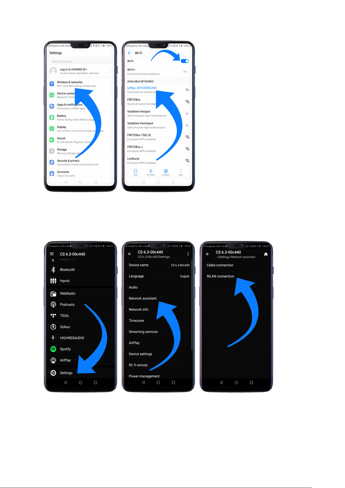
ü Start the RC X App and select the AVM device from the start menu.
ü Call up the menu item Network assistant in the Settings and select WLAN connection.
ü Use Scan to search for available wireless networks and select the wireless network you
want to use as soon as it appears in the search results. In the example below, the WLAN
network is named FRITZ!Box. A WLAN network name is also called SSID.
ü Enter the password for the WLAN network and complete the setup via Connect.
16
Page 17

ü Call up the menu item Network Info in the Settings. In the Wireless section, you can view
details of the WLAN configuration that has been carried out.
1.10.2.4 Setup via optional RC 9 remote control
Before you can set up a wireless WLAN connection via the RC 9, both components must first
be connected to each other. This one-time procedure is called Pairing and is described in
section 1.8.1. A detailed description of the entire functionality of the RC 9 remote control can
be found in a separate operating manual at www.avm.audio.
17
Page 18

ü First, perform the Pairing procedure as described in section 1.8.1 and select the newly set
up AVM device on the RC 9 using the Device Selection menu item. You can reach this
menu item via the System Settings menu that you call up by pressing the Settings button
(tool symbol) of the RC 9.
ü On the RC 9, select the menu item Settings (Einstellungen) in the main menu by pressing
the upper or lower navigation button several times.
ü By pressing the Enter button, select the menu item Network assistant and WLAN
connection.
ü By selecting the Scan menu item afterwards, your AVM device searches for available WLAN
networks and lists them in an overview.
ü Select the desired WLAN network and enter the network key (WLAN password) via the input
keys of the RC 9 after pressing Key.
ü Confirm the entered network key (WLAN password) by pressing the Enter button and select
Connect. In the following overview Network Info, the Wireless section displays details of
the WLAN configuration.
1.11 Software & Firmware Updates
For maximum ease of use and to get the most out of your device, it is necessary to keep both
the firmware of the integrated AVM X-STREAM Engine® and the RC X App up to date. The
latest version of the RC X App can be downloaded from the Apple App Store or the Google
Play Store. To check on the installed AVM X-STREAM Engine® firmware version, use the RC
X App or the optionally available RC 9 remote control. Also, make sure your device has an
active internet connection before you perform either of the following two steps (see section
1.10).
1.11.1 AVM X-STREAM Engine® Update via the RC X App
ü Call up the menu item Firmware Update in the Settings and select Check for Online
Update.
ü If a new version is available under SW Update or Host Update, install it by clicking Install
Update.
ü The device restarts to install the update. Do not switch off the device and wait until the
update process is completely installed. The update process will be shown on the display of
the device if necessary.
ü Once the update process is complete, the device will reboot and be ready for use again.
18
Page 19

ü Call up the Settings of the RC X App. In the Version section, you can view details about
3,5mm stereo
+5V supplyIR-SignalGND
infrared input
the currently installed firmware version.
To install a software update via a USB stick, please consult your dealer who will be happy to
assist you with the update.
1.11.2 AVM X-STREAM Engine® Update via the RC 9 remote control
ü Select the desired AVM device on the RC 9 using the menu item Device Selection. You
can reach this menu item via the System menu, which you call up by pressing the Settings
button (tool symbol) on the RC 9.
ü On the RC 9, select the menu item Settings in the main menu by pressing the upper or
lower navigation button several times.
ü Call up the menu item Firmware Update and select Check for Online Update.
ü If a new version is available under SW Update or Host Update, install it by clicking Install
Update.
ü The device restarts to install the update. Do not switch off the device and wait until the
update process is completely installed. The update process will be shown on the display of
the device if necessary.
ü Once the update process is complete, the device will reboot and be ready for use again.
ü Select the menu item Settings in the main menu by pressing the upper or lower navigation
key several times. In the Version section you can view details about the currently installed
firmware version.
To install a software update via a USB stick, please consult your dealer who will be happy to
assist you with the update.
1.12 External infrared control
The connector for an external infrared receiver (37) may be used to control the AVM device with
an external infrared signal. For this purpose, the cable coming from the external receiver must
be assembled with a 3.5 mm stereo jack plug. The voltage output must also have a logic level
(LOW < 0.4V, HIGH >2.4V, max 5V).
Pin assignment for external infrared receiver (37)
19
Page 20

2 Basic operation
2.1 First operation / self test
When switching on for the first time, a so-called self-test is performed if the device has been
completely disconnected from the power supply or switched off via the mains switch (35). The
device checks the configuration and functionality of the installed components. This process is
indicated by a flashing Standby LED (7) and may take a few seconds.
2.2 Switching on / stand-by
With the power button (1) you can toggle between operation and standby mode. In standby
mode the display is dark and the standby LED (7) is on. As soon as the machine is in operating
mode, the standby LED (7) goes out and the display (9) is activated.
Tube warmup (MP 8.3)
Due to the warm-up phase of the integrated tube line stage, the power-on time of the MP 8.3
is extended by approx. 30 seconds.
CAUTION: When switched to stand by the unit is still connected to the mains. In case of a
thunderstorm or if you leave the house for a longer time, we recommend you switch the
amplifier off by using the mains switch (35) or pull the mains plug (34).
2.3 Display
When the unit is on, the display (9) shows information about the current settings and state of
your Media Player. Apart from informations about the operating status (CD Player, Digital Input
etc.) the lower line shows you currently active settings of the D/A converter: On the left-hand
side the sample rate (e.g. PCM 192kHz),) is displayed. On the right-hand side, you will find the
current filter setting (SMOOTH or STEEP).
2.3.1 Display in CD player mode
TRACK
On the left-hand side both the current title is displayed (big figures) and the total number of
available tracks of the inserted CD (small figures).
TIME
At the centre of the display the total duration of an inserted CD is displayed, while stopped
(STOP). As soon as the CD is played (PLAY) or paused (PAUSE), the time already elapsed of
the current track is displayed.
20
Page 21

STATUS
The current operating status (STOP, PLAY, PAUSE) is also shown in the upper part of the
display (9).
PROG
In case of a currently active track programming both the currently playing track and the total
number of programmed tracks is displayed on the left-hand side (for example PROG 2/17).
RND
In case the random play mode is activated, the currently playing track and the total number of
programmed tracks are displayed on the left-hand side (for example RND 5/12).
2.3.2 Display in D/A converter mode
On the left-hand side the name of the currently selected input is displayed under SOURCE. If
there is no incoming signal available at the currently selected input, NO SIGNAL or NO USB is
shown next to the input name.
2.4 CD Player
2.4.1 Playable disc formats
The CD player is suitable for playing all 'Red Book' compliant audio CDs. Red Book is an audio
CD standard set by Philips and Sony. Furthermore, self-burned CDs can also be played as long
as they comply with the 'Red Book' standard.
NOTE: Some manufacturers produce CDs that do not comply with the Red Book standard for
copy protection reasons. We (and many other equipment manufacturers) cannot guarantee that
such CDs will play properly. If you have purchased such a CD, you can return it to your dealer
(even if you have already opened the package!) However, you can only do so if the CD case
does not clearly show a notice on the CD that it is copy protected and that the CD does not
conform to the standard.
ATTENTION: Do not use mats or stickers placed on the CD. These can impair music playback
or interfere with the drive mechanics. We also advise against the use of small 8cm CDs and
shape CDs. These could get stuck in the drive and cause defects in the mechanics.
2.4.2 Insert / eject
Insert a CD
Your Media Player is provided with a slot-in CD drive (8). Insert the CD (coverside up) and push
slightly. The drive will now automatically draw the disc inside. After that the player reads the
TOC (table of contents) and shows it on the display. Most left is the number of the actual track
followed by the total number of tracks on the CD (for example 1/17). The middle of the display
shows the total playing time of the CD.
21
Page 22

NOTE: If there is already a CD in the drive, the slot is blocked. If the CD is not readable or if a
data CD or DVD is inserted by mistake, the DISC ERROR indicator will appear and the CD can
be ejected by pressing the EJECT button (15).
Eject CD
Press the EJECT button (15). Then the disc will be ejected. If no CD is inserted, the display
shows NO DISC.
AUTOPLAY
If CD is not selected as source the unit will automatically change to CD from any other input as
soon as a CD is inserted. If AUTOPLAY is activated (see 3.1.6), the CD player will start playing
automatically every time a CD is inserted. If AUTOPLAY is deactivated, the CD player will read
the TOC (table of contents) of the inserted disc and then go to STOP mode.
2.4.3 CD playback
If a disc is inside playing is started by pressing the PLAY button (12). If you press PAUSE (11)
the unit will go into the pause mode until PLAY (12) or STOP (10) is pressed. The current
operating status (PLAY, PAUSE, STOP) is shown in the upper part of the display (9).
Furthermore, the display shows the actual playing time, the actual title number and the total
number of titles.
2.4.4 SKIP / SEARCH
With the SKIP keys (13, 14) you can select a title, or search for a certain position within the
current title during playback.
When a CD is inserted and the player is stopped
Short tapping switches to the next or previous title. Pressing and holding for longer will
automatically advance to the next or previous title.
While a CD is playing
Short tapping switches to the next or previous title. If more than five seconds of playing time
have elapsed, the first press of the left SKIP button (13) jumps to the beginning of the title.
Pressing the key again will jump to the previous title.
A longer press activates a fast forward or rewind to search for a specific position within the
current title.
2.4.5 Repeat
Press the REPEAT button (6) once to repeat the actual title, twice to repeat the whole CD or
the programmed sequence. A third pressing returns to the normal playing mode. The repeat
state is displayed in the upper line of the display (RP ONE / RP ALL).
22
Page 23

2.4.6 Programing an individual playlist
Press the PROG button (4) to enter the programming menu. In the upper left corner of the
display, the title number (TRCK) of the title to be reprogrammed is shown, which can be
selected with the two selection keys (2, 2). Below this, the length of this title is displayed (TIME=
xx:xx).
Use the PLAY key (12) to insert a selected title into the program. The display shows the total
number of already programmed titles in the upper right line (PGM-QTY xx). Below this the
display shows the total programmed playing time (P-TIME xx:xx).
With the right SKIP button (14) the program is stored and can be started afterwards with the
PLAY button (12). Use the left SKIP key (13) to leave the programming menu. Already
programmed titles will be deleted and the unit will return to normal operating mode.
2.4.7 Programming an individual playlist (example)
The CD inside the player contains 15 titles. You want to play only titles 7, 3 and 8.
• Press the PROG button (4) to enter the programming menu. Since no titles have been
programmed yet, PGM-QTY 0 (right) and TRCK 01/15 (left) appear in the upper line of
the display.
• Select title 7 using the Option keys (2,3). The display shows TRCK 7/15.
• Now add the selected track to the playlist by pressing PLAY (12).
• Select title 3 using the Option keys (2,3). The display shows TRCK 3/15.
• Now add the selected track to the playlist by pressing PLAY (12).
• Select title 8 using the Option keys (2,3). The display shows TRCK 8/15.
• Now add the selected track to the playlist by pressing PLAY (12).
• Press PROG (4) to finish the programming and store the playlist.
NOTE: The maximum number of programmed tracks is 99. The maximum program duration is
99 minutes.
2.4.8 Deleting a programmed playlist
To delete a programmed playlist, press the PROG button (4) and then the left SKIP button (13).
Ejecting a CD or switching off the device also deletes a playlist. When switching to another
source, however, the programmed playlist is retained.
2.4.9 Random
Press the PROG button (4) to enter the programming menu. By pressing the right SKIP button
(14) a random playback sequence (RANDOM) is automatically programmed, which can be
started by pressing the PLAY button (12).
23
Page 24

2.5 Source selection
In addition to the integrated CD drive, the device is equipped with a large number of digital
inputs that can be activated using the two option keys (2, 3). The current source is shown on
the left side of the display (9) under SOURCE.
Selecting additional sources such as Spotify Connect®, Apple AirPlay, TIDAL, QOBUZ,
HIGHRESAUDIO, Webradio, Podcasts, Music Server or USB (STICK HDD) (29) is only
possible using the optionally available RC 9 remote control or the free RC X App for iOS and
Android.
NOTE: If you switch to another source during CD playback, the CD will stop before changing
the input. This process may take a few seconds. If a digital input is selected and no compatible
digital signal is present, the display (9) shows NO SIGNAL or NO USB instead of the volume
indicator. In this state volume settings (see section 2.6) cannot be adjusted due to the selected
digital input.
2.6 Volume setting
If the VARIABLE option is activated via the Personal Setup menu (see section 3.1.1), the
playback volume of the selected source can be adjusted via the front panel. The display will
then show the currently selected volume value of 0 - 100 dB in large letters in the right area
and can be adjusted in steps of 0.5 dB or 2 dB by pressing and holding the option keys < > (2,
3).
ATTENTION: Please note that even if the VARIABLE option is activated, a short press of the
two option buttons < > (2, 3) causes a change of the input source. To change the playback
volume, however, a longer press of the two selection buttons of approx. 1 second is required.
NOTE: With the optionally available RC 9 remote control, the volume is always changed in
steps of 2 dB.
2.7 Samplerate and filter setting
By pressing the FILTER button (5) once or several times, you can choose between available
sample rates and filter setttings for a specified source (CD or digital input). The currently
selected sample rate is displayed at the bottom left corner (44.1, 48, 88.2, 96, 176.4, 192, 352,
384 kHz). The NAT indicator stands for "Native" and means that the applied sample rate of the
signal is directly processed and converted. CNV, on the other hand, stands for "Conversion"
and means that up- or downsampling to the selected sample rate is performed.
PLEASE NOTE that only the settings NAT / STEEP or NAT / SMOOTH are available if USB is
selected.
You may select the STEEP and SMOOTH filter settings according to your sonic preferences.
Depending on the signal being reproduced, different filter settings can produce optimal results.
24
Page 25

Technically speaking, STEEP means steep filtering at the end of the band with a flat amplitude
frequency response but strong phase shift. SMOOTH, on the other hand, filters less steeply
causing a small amplitude drop before the end of the band, but a smaller phase shift. The
selected filter setting is only valid for the current input and remains stored even after the unit is
switched off. It can be changed at any time by pressing the FILTER key (5) again.
2.8 USB B digital input
If a digital signal from a computer (PC or Mac) is connected to the USB B digital input of your
Media Player (22), you can choose between two different modes (LOW RES or HIGH RES) by
pressing the PROG button (4).
LOW RES can be used to play back a digital input signal with a sample rate of up to 96kHz
without the need for an additional audio driver on your Windows PC or Mac.
HIGH RES can be used to play back a digital input signal with a sample rate of up to 384kHz/24
Bit (PCM) without the need to install an audio driver on your Mac. PC systems with Windows
on the other hand require an additional driver, which is available for free download in the
download area at www.avm.audio.
When a digital signal is applied, the currently active data format (PCM or DSD) is shown in the
lower left area of the display next to the sample rate.
Please note that for playback of DSD64 and DSD128 the HIGH RES setting is always required.
25
Page 26

3 Advanced Settings
3.1 Personal Setup
The personal setup offers a range of settings to individualize tyour device according to your
personal needs. To enter the personal setup menu, please switch off your device on the rear
of the unit at the mains switch (35). Keep the PROG button pressed (4) while you switch on the
unit again (35). As soon as the display first shows Entering setup and then *** personal setup
***, you can release the PROG button (4). Use the option keys < > (2, 3) to select a desired
menu item and use the PLAY key (12) to enter the corresponding submenu. Then use the SKIP
buttons (13, 14) to make the desired setting. Press the STOP key (EXIT) to return to the main
menu and select further menu items of the personal setup via the PLAY button (12). By pressing
the STOP key (EXIT) again, you can leave the personal setup. The settings made are now
saved (Exit & Save Settings appears in the display). Afterwards the device performs a reboot
and is ready for operation again.
3.1.1 Set volume limit
With this menu item you can limit the maximum output volume up to 50%. This feature can be
useful to avoid rapid volume jumps caused e.g., by accidental misuse of the volume control in
the RC X App for iOS and Android. The default setting is 70% and is intended as a protection
mechanism to protect other components in your system (e.g., speakers) and last but not least
your ears from drastic volume jumps which can be triggered e.g., by accidentally operating the
volume control of the RC X App for iOS and Android.
3.1.2 set display brightness
Sets display brightness 25% to 100%.
NOTE: The setting 100% can lead to "burn in" effects on the display if the unit is operated in
this setting for a very long time. In order to avoid such "burn in effects" please switch the unit
to stand by, if not in use.
3.1.3 skip unused inputs
If you do not need all digital inputs, the unused inputs can be deactivated (SKIPPED). When
selecting the source, all inputs defined as SKIPPED are automatically skipped and are also not
selectable via remote control. The settings can be adjusted at any time by calling up the menu
item again.
3.1.4 Define input names
With the menu item define input names you can change the input names of sources on the
display (9). A name has a maximum of 8 characters. With the option keys < > (2, 3) you select
the desired input. In the left half of the display the current name of the selected input is shown,
26
Page 27

in the right half the new name. The edited character is marked with an underscore. With the
REPEAT button (6) you determine the position of the character to be changed, with the SKIP
buttons (13, 14) you set the desired character. Short tapping switches to the next / previous
letter.
3.1.5 Set fixed volume
VARIABLE
If the VARIABLE option is activated, the playback volume of a source can be adjusted using a
remote control, the RC X App or the front panel control. See section 2.6 Volume Control.
ATTENTION: Please note that even if the VARIABLE option is activated, briefly pressing one
the two option buttons < > (2, 3) will cause a change of the input source. To change the
playback volume, however, a longer pressing of the two option buttons of approx. one second
is required.
FIXED VOL
If the FIXED VOL option is activated, the signal is reproduced with a fixed gain setting. It is not
possible to change the volume via remote control or the selection buttons on the front panel.
In the general operating mode, the FIX indicator on the right side of the display (9) indicates
this setting.
3.1.6 Set autoplay
If the AUTOPLAY function is activated, the unit will automatically start playback after inserting
a CD without the need to press the PLAY button first. In addition, the unit automatically
switches from an active digital input to CD mode. In the factory setting, this function is activated
(on). If the AUTOPLAY function is deactivated, however, an inserted CD is only read in the
background - without changing to CD mode.
3.1.7 Set IR control
In addition to control your device via the optionally available RC 9 remote control or the free
RC X App for iOS and Android, a range of essential functions can also be controlled via the
classic RC 3 or RC 8 infrared remote controls. In order to receive a respective infrared signal
of the RC 3 or RC 8, please make sure to activate the set ir control function (ON).
3.1.8 set auto standby
To save energy, the unit is equipped with a circuit that automatically puts the unit into standby
mode if there is no music signal on the currently active input for more than 20 minutes. This
function is activated (ACTIVE) by default and can be deactivated permanently with this menu
item (NOT ACTIVE).
The selected setting is permanently stored when leaving the Personal Setup, but can be
changed at any time by calling up the Personal Setup again.
27
Page 28

3.2 Reset (Factory Settings)
The RESET option offers you the possibility to reset the device to its original factory settings
and thus to its delivery state. To do this, first switch the device to standby mode using the
power button (1) and then switch it off completely using the mains switch (35).
Now keep both buttons REPEAT (6) and STOP (10) pressed while switching on the device with
the mains switch (35). As soon as the message Entering setup appears in the display (9), the
two keys can be released.
Press the PLAY button (12) to reset all settings. The PAUSE key (11) only resets the input
names (see section 0). After pressing one of the two keys, the device performs the
corresponding reset and then restarts to the general operating mode.
By pressing the STOP key (EXIT) you may leave the menu without making any changes.
Alternatively, a complete reset to the factory settings may also be performed using the RC X
App for iOS and Android or the RC 9 remote control. To do this, select the menu item Reset
device in the Settings of the RC X App or the RC 9 remote control and confirm the reset. The
device will now perform a reset to its factory settings and restart to its general operating state.
28
Page 29

4 Appendix
4.1 Cleaning
Surface and pressure of the housing are largely scratch-resistant. It can be cleaned with mild
soapy water or a glass cleaner and a soft duster.
ATTENTION: During cleaning, liquid must never be allowed to enter the interior of the housing.
For safety reasons, the power cord should also be disconnected before damp wiping. Do not
use any solvents or abrasive cleaners that could damage the surface or printing on the housing.
4.2 Troubleshooting
Some putative defects are often caused by mistakes in operation. Sometimes other units
connected to the amplifier can cause problems. We therefore kindly ask you to read the
following tips before consulting your dealer or us.
1. No playback
a) Inadvertent switching to standby. Press power button (1).
b) If the control LED (7) and display (9) do not light up a fuse can be blown due to overvoltage
(e.g. in case of a thunderstorm etc.). Please contact your dealer.
2. RC 9 remote control doesn’t work
a) Charge the included lithium-ion battery of the optionally available RC 9 remote control.
b) Point with the remote control transmitter directly to the unit.
c) Reconnect the RC 9 remote control with your device. This process is also referred to as
Pairing. In order to start the pairing process, please follow the instructions as described in
section 1.8.1.
3. The display shows „no disc“, although a CD is inserted
a) Please make sure the CD is not a data disc, has not been damaged and is inserted with the
correct side facing up
b) Please clean your CD with a soft cleaning cloth.
29
Page 30

4.3 Conditions of warranty (EC only)
If despite expectations a defect occurs that cannot be repaired by yourself or your dealer, we
undertake the repair of your unit free of charge for up to three years from date of purchase. The
warranty covers the costs of material and working time, transport costs are to be borne by the
owner.
Provisions for this warranty are:
• The unit must have been purchased from an authorised dealer. Equipment from other
sources will not be repaired, not even at charge.
• The warranty registration card, together with a copy of the bill of sale, must be received
by us within four weeks of the date of purchase.
• The defect must not have been caused by improper handling or misuse.
• Return the unit to us only in its original packing. If this is not possible, we are entitled to
refuse acceptance. We will not assume responsibility for transport damage under any
circumstances.
• A short description of the defect is to be included with the returned unit.
• In cases of doubt, we reserve the right to request a copy of the bill of sale.
• We also reserve the right to levy a handling charge for items returned without good or
valid reason, or if the unit proves to be not defective.
NOTE: If you are returning the unit from a country other than Germany you should ensure that
correct export documents are obtained. We cannot accept any charges for costs arising from
improper or incomplete export documentation.
If you have purchased your unit from a dealer outside Germany please refer to him or the
relevant importing firm to process the warranty.
NOTE: Energy consumption in stand by mode
To power up your AVM device at any time via the RC X App for iOS and Android, the integrated
AVM X-STREAM Engine® remains in standby mode and is always ready for operation. Please
note that the power consumption is not below 0.5 VA as usual, but increases to about 5.5 VA.
If you want to save this energy, switch off the unit completely with the rear mains switch (34)
after switching to stand-by mode.
Changes reserved without notice. 2021/01/14.
30
 Loading...