

AVM CS 6.3 Silver, CS 8.3 Silver, CS 8.3 Cellini Chrome, CS 8.3 Black, CS 6.3 Cellini Chrome CS 6.3 CS 8.3 Operating Instructions.pdf
...Page 1

Operating instructions
OVATION CS 6.3
OVATION CS 8.3
Page 2

Page 3

Caution
This unit contains a class 1 laser diode. Do not open. Invisible laser radiation can damage
your eyes.
Laserdiode Typ: Ga-Al-As
Wavelength: 755 - 815 nm (25 °C)
Output power: max. 0,7 mW max.
Declaration of conformity (for EC only)
We herewith confirm, that the unit to which this manual belongs fulfills the EC rules necessary
to obtain the sign
the necessary measurements were taken with positive results.
AVM Audio Video Manufaktur GmbH
Daimlerstraße 8
D-76316 Malsch
Germany
www.avm.audio
info@avm.audio
Page 4

Dear customer
Thank you for purchasing this AVM product. You now own a versatile, excellent sounding highend component. Before enjoying your music, please read this manual carefully. After that you
will know how to use your new CS 6.3 / 8.3 in the optimal way.
Please note: The range of functions of your AVM hifi component can be easily expanded by
means of a software update at any time. Hence, the present operating instructions will require
continued updates going forward. You can always download the most current version from our
website at www.avm.audio.
Udo Besser – AVM Owner & General Manager
Page 5

Table of contents
1! Getting started .................................................................................................................... 6!
1.1! What’s in the box? ........................................................................................................ 6!
1.2! Control and operating elements ................................................................................... 6!
1.3! Installation and cooling ................................................................................................. 7!
1.4! Connection to mains .................................................................................................... 7!
1.5! Connections of analog sources .................................................................................... 8!
1.6! Connection of digital sources ....................................................................................... 8!
1.7! Connection of analog recording devices ...................................................................... 8!
1.8! Connection of digital recording devices ....................................................................... 8!
1.9! Connecting a subwoofer .............................................................................................. 8!
1.10! Connecting loudspeakers ............................................................................................. 8!
1.11! Tuner antenna ............................................................................................................... 9!
1.12! RC 9 remote control ..................................................................................................... 9!
1.13! RC X App for iOS and Android ..................................................................................... 9!
1.14! Network installation (LAN, WiFi) ................................................................................... 9!
1.15! Software & Firmware Updates ................................................................................... 18!
2! Basic operation ................................................................................................................. 20!
2.1! First operation / self test ............................................................................................. 20!
2.2! Switching on / stand by .............................................................................................. 20!
2.3! Selecting the signal source ........................................................................................ 20!
2.4! Volume settings .......................................................................................................... 21!
2.5! CD Player .................................................................................................................... 21!
3! Advanced Settings (MENU) ............................................................................................. 24!
3.1! Global settings ............................................................................................................ 24!
3.2! Line Settings (XLR, RCA) ............................................................................................ 26!
3.3! Digital inputs (COAX, OPTO, USB) ............................................................................. 26!
3.4! Personal Setup ........................................................................................................... 27!
3.5! Factory Reset ............................................................................................................. 29!
4! Appendix ........................................................................................................................... 30!
4.1! Cleaning ...................................................................................................................... 30!
4.2! Troubleshooting .......................................................................................................... 30!
4.3! Conditions of warranty (EC only) ................................................................................ 31!
Page 6

1 Getting started
1.1 What’s in the box?
• OVATION CS 6.3 / 8.3 Compact Streaming CD-Receiver
• WiFi antenna
• Power cord (in some countries)
• Optional accessory: RC 9 remote control with docking station, power supply unit,
USB charging cable
CAUTION: After unpacking, please check the scope of delivery to ensure that all parts have
been supplied and are undamaged. In case the original packing has already been opened, please
contact your local dealer. Often, your dealer prepares your new device prior to delivery to adapt
and change the configuration to your personal needs.
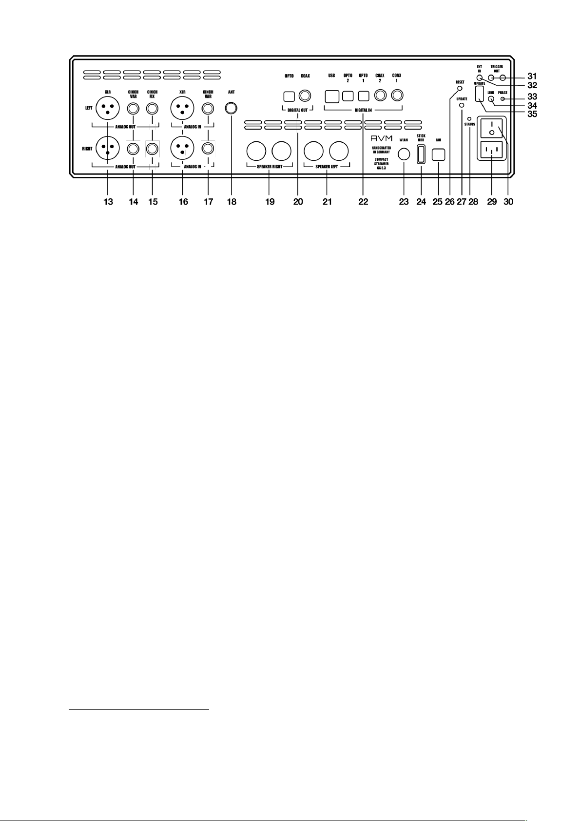
1.2 Control and operating elements
The numbers in the drawings below mark the control elements. They refer to the numbers in
the text, where the operation of the unit is described.
1 Power button (on/off)
2 Source selector
3 Control LED
4 CD slot
5 Menu button (soft key)
6 Menu button (soft key)
7 Menu button (soft key)
8 Menu button (soft key)
9 Menu button (soft key)
10 Display
11 Volume knob
12 Headphone Output
6
Page 7
*
13 Analogue outputs (XLR)
14 Analogue outputs (RCA/CINCH VAR)
15 Analogue outputs (RCA/CINCH FIX)
16 Analogue input (XLR)
17 Analogue input (RCA/CINCH)
18 Antenna socket (FM Tuner)*
19 Speaker terminal right
20 Digital output (OPT, COAX)
21 Speaker terminal left
22 Digital inputs (USB-B, OPT 1-2, COAX)
23 WiFi antenna socket (WLAN)
24 USB-A port for storage media (STICK
HDD)
25 LAN port (Ethernet)
26 Reset button (Streaming module)
27 Update button (Streaming module)
28 Status LED
29 Mains connector
30 Mains switch
31 Trigger outputs
32 Connector for external IR receiver
33 Phase LED (illluminates when
34 Link
35 Configuration port (Firmware)
1.3 Installation and cooling
The unit can become hot depending on demanded output power or environmental temperature.
Therefore, it is important, that the cooling air can flow unhindered into the air inlet in the bottom
and flow out through the holes in the rear panel. Direct exposure to sunlight is not
recommended because this will heat up the unit and may cause unwanted malfuctions.
1.4 Connection to mains
Connect the unit to the mains outlet (29) by using the power cord which is (in some countries)
delivered together with the unit. Make sure that mains voltage is according to the value printed
on the rear panel of the amp (near mains connector).
CAUTION: Keep the unit switched off (30) until all audio connections are made.
FM Tuner functionality requires an
optionally available FM Tuner Module.
7
Page 8

1.5 Connections of analog sources
Connect the outputs of your analog sources to the corresponding inputs (16, 17). The left
channel goes to the upper row, the right channel to the bottom row.
1.6 Connection of digital sources
Connect the output of your digital sources with the corresponding input (22): USB-B input
(USB), optical inputs (OPTO 1, OPTO 2), coaxial input (COAX).
1.7 Connection of analog recording devices
Connect the inputs of your analog recording device with the analog outputs CINCH FIX (15).
The analog outputs of the recording device can be connected with the high-level inputs (16,
17).
1.8 Connection of digital recording devices
Connect the inputs of your digital recording device with the optical or coaxial outputs (20). The
signal on the digital outputs depends on the selected source (e.g. CD Player, DIG COAX, DIG
OPT).
PLEASE NOTE: Incoming signals via the USB-B input (22) are not looped through the digital
outputs (20).
1.9 Connecting a subwoofer
If you use an active subwoofer (with a built-in power amplifier), simply connect the inputs to
the CINCH VAR outputs (14) and adjust the bass level at the subwoofer.
1.10 Connecting loudspeakers
Connect the speakers to the speaker terminals (19, 21). Use only good speaker cables with
sufficient diameter. Make sure, that the red terminals are connected to the red or "+“ terminals
of the speakers and the black terminals to the black or “-“ terminals of the speakers.
8
Page 9

1.11 Tuner antenna*
*
Connect the FM antenna cable to the antenna socket ANT (18).
1.12 RC 9 remote control
The optionally available RC 9 remote control allows for easy and comprehensive control of your
devices. Before you can use the RC 9 together with your device, both components need to be
connected. This process is also referred to as Pairing. In order to start the pairing process,
please follow the instructions as described in section 1.12.1. A detailed description of the entire
functionality of the optionally available RC 9 remote control can be found in a separate manual
on the AVM website at www.avm.audio.
1.12.1 Pairing
In order to control your device with a RC 9 remote control, both components need to be linked
first. This process is also referred to as Pairing. To start the pairing process, please switch off
your device by using the mains switch (30) on the rear side of the unit. Now please navigate to
the Systems Settings menu on your RC 9 remote control by pressing the Settings key and
navigate to the menu item Start Pairing without selecting it with the Enter key yet. Switch on
your device by using the mains switch (30) on the rear side of the unit and immediately press
the Enter key of your RC 9 remote control to now start the Pairing process. The name of a
succesfully detected device will instantaneously be shown on the display of your RC 9 remote
control and can be adjusted by using the alphanumeric input keys of the RC 9 remote control.
After confirming the name of the paired device with the Enter key, you can also choose one of
four available Hotkeys. Details on how to use the Hotkey function of your RC 9 remote control
can be found in a separate RC 9 manual on the AVM website at www.avm.audio. By pressing
the Enter key on your RC 9 remote control again, the pairing process is completed.
1.13 RC X App for iOS and Android
The RC X App for iOS and Android will turn your smartphone or tablet into an easy-to-use
remote control and provides a variety of intuitive features to get the most out of your networkenabled AVM device with integrated AVM X-STREAM Engine®. The RC X App is available free
of charge and can be downloaded from the Apple App Store and the Google Play Store.
1.14 Network installation (LAN, WiFi)
To use the extensive streaming and networking features such as Spotify Connect®, Apple
AirPlay, TIDAL, QOBUZ, HIGH RATE AUDIO, web radio, podcasts or music servers, your
device must be connected to your home network or the internet via a router. You can choose
from a wired LAN connection (25) or a wireless WiFi connection (23). When screwing the
FM Tuner functionality requires an optionally available FM Tuner Module.
9
Page 10

supplied WLAN antenna onto the corresponding WLAN antenna connector (23), please make
sure that the antenna is aligned straight. Only then angle the antenna into the desired position.
LAN vs. WiFi
If you have the choice between a wired LAN or wireless WLAN connection, we generally
recommend that you use a wired LAN connection, which usually provides higher bandwidth
and is also less susceptible to interference and less dependent on the data traffic of your entire
network.
NOTE: All AVM devices with integrated AVM X-STREAM Engine® generally prefer a wired
network connection and will automatically access it once a LAN/network cable is installed on
the device (25). To still ensure smooth continuous operation via WLAN/WiFi, please remove
any LAN/network cables from the LAN/network connection (25). Otherwise the device will reestablish a wired network connection via LAN even during operation.
Please make sure to carefully follow all steps below to successfully set up a wired LAN
connection or a wireless WiFi connection.
1.14.1 Setting up a wired LAN connection
All AVM devices with integrated AVM X-STREAM Engine® are hot-pluggable. This means
that setting up a wired network connection does not require the AVM device to be restarted or
turned off and on again. Instead, a network cable (LAN cable) can be connected while the
device is running and a network connection is established immediately.
ü Plug a LAN cable from your local router or network switch into the LAN port of the device
(25).
ü The device automatically connects to your home network via the connected LAN cable
and is ready for use.
ü Make sure your smartphone or tablet is connected to your local network and start the
RC X App. After a short startup process, the RC X App automatically searches for
available AVM devices in your local network and lists them with their device names and IP
addresses. You can recognize an IP address by a sequence of numbers separated by
several dots. Often an IP address starts with "192.168.xxx.x".
ü Select an available device from the list by tapping it and wait a short moment until a
connection between your smartphone or tablet and the device is established.
10
Page 11
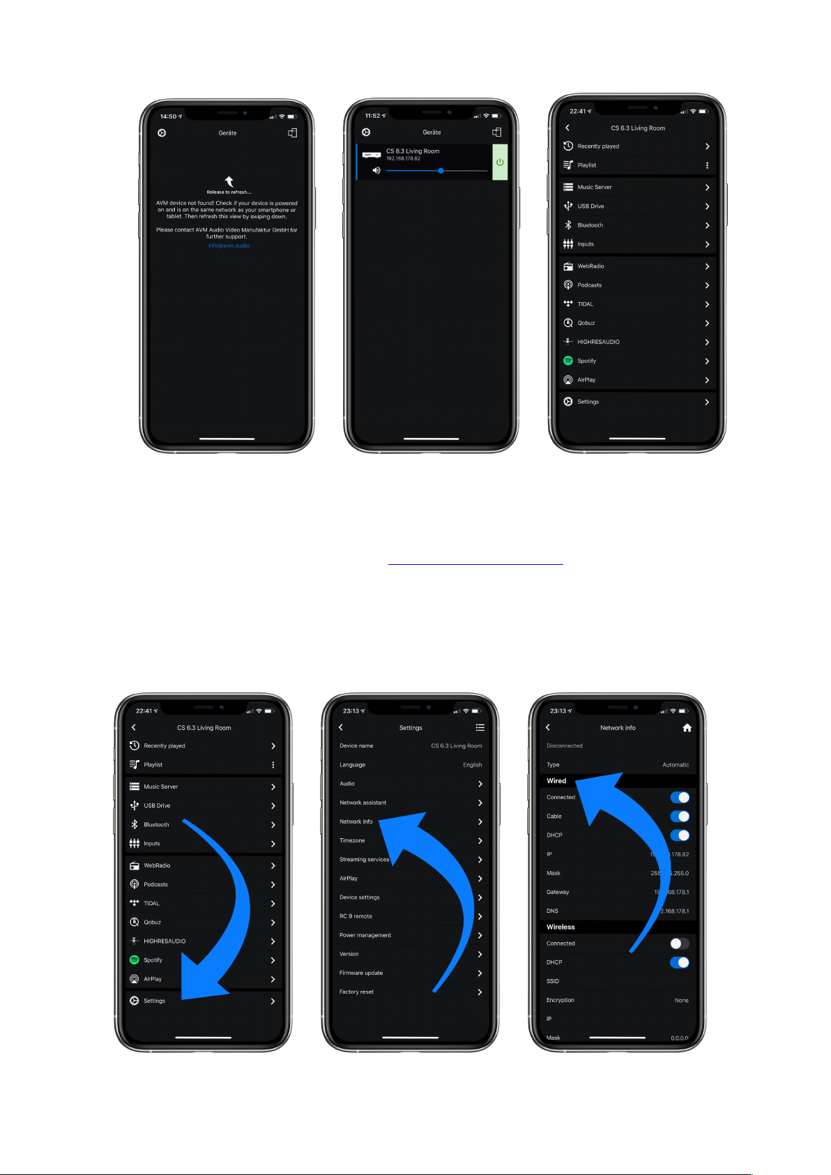
NOTE: If you do not see any available devices, check if the network cable is installed
correctly and is on the same network as your smartphone or tablet. Then drag the view in the
RC X app slightly down to search for available devices again. Please also note the
RC X app is only compatible with AVM models with integrated AVM X-STREAM Engine®.
You can find a current model overview at: www.avm.audio/rc-x-app.
ü To check on the network status, start the RC X app and select the AVM device.
ü Call up the menu item Network info in Settings. In the Wireless section, you can check
on the WLAN configuration that has been established.
11
Page 12

1.14.2 Setting up a wireless WiFi connection
To set up a wireless network connection (WLAN/WiFi) you have several options:
ü WPS
ü AirPlay configuration for iOS
ü RC X App for Android via WiFi Access Point
ü RC 9 remote control
1.14.2.1 Setup via WPS
WPS (Wi-Fi Protected Setup) is a standard for easy and secure wireless network connection
with encryption. All you need is a WiFi router with WPS function (please refer to the relevant
documentation to find out whether your router is equipped with WPS). The setup of a WPS
connection is done via the Personal Setup Menu of your AVM device. For details on the
complete range of functions of the Personal Setup menu, please refer to section 3.4 Personal
Setup.
ü To call up the Personal Setup Menu, switch off the device completely using the power
switch on the rear panel (30).
ü Now press and hold the menu button on the right below the display and switch on the
device again with the power switch (30). As soon as the display first shows Entering setup
and then *** personal setup ***, the menu button can be released. In the Personal Setup
menu, individual menu items can be selected with the menu buttons < ITEM> and activated
accordingly with the menu button SELECT.
ü Now select the menu item set WLAN via WPS by pressing one of the menu buttons <
ITEM>.
ü Activate the WPS function by pressing the SELECT menu button. The display shows WPS
in progress.
ü Now activate the WPS function on your WiFi router within two minutes.
ü As soon as your AVM device has successfully established a WLAN connection via WPS,
the name of the connected WLAN is shown on the display, e.g.: Joined WLAN: WLAN
Name (SSID).
ü To finish the process, press the BACK menu button and then exit the Personal Setup menu
by pressing the EXIT menu button. After a short save procedure (the display shows Exit &
Save Settings) the device restarts and switches to normal operating mode.
ü Your AVM device is now connected to your local wireless network (WLAN/WiFi) and ready
for operation.
ü To check on the network status, start the RC X app and select the AVM device. Call up the
menu item Network info in Settings. In the Wireless section, you can check on the WLAN
configuration that has been established.
12
Page 13

1.14.2.2 Setup via AirPlay configuration for iOS
ü First switch off the AVM device completely using the power switch on the rear panel (30)
and wait a short moment until you switch it on again using the power switch.
ü As soon as your AVM device has completed the startup process and is in the general
operating state, open the WLAN menu in the Settings of your iPhone or iPad. Make sure
the WLAN function is enabled and your iPhone or iPad is connected to the desired WLAN.
13
Page 14

ü Select the AVM device you want to connect to your WLAN in the WLAN menu under the
menu item SET UP NEW AIRPLAY SPEAKER. In the example below, the AVM device is
listed as CS 6.3-00c440. Wait a moment if the device is not immediately displayed. Your
iPhone or iPad will continuously search for new devices and update the view of available
WLAN networks at short intervals. If the AVM device does not appear even after a short
wait, repeat the AVM device power-up procedure as described above.
ü In the following Airplay Setup menu, check that the desired WLAN is selected under
NETWORK and, if necessary, change the device name for your AVM device under Speaker
Name. Optionally set a password. Then start the connection process via Next. The WLAN
access data including the password is now automatically transferred from your iPhone or
iPad to your AVM device. As soon as the configuration is finished, you will receive a
corresponding feedback, which you confirm with Done. Your AVM device is now integrated
into your WLAN and ready for operation.
ü To check on the network status, download the RC X App for iOS from the Apple App Store
and install it on your iPhone or iPad. Then start the RC X app and select the AVM device
from the start menu.
ü Call up the menu item Network Info in the Settings. In the Wireless section, you can view
details of the WLAN configuration that has been carried out.
14
Page 15

1.14.2.3 Setup via RC X App for Android via WiFi Access Point
ü Download the RC X App from the Google Play Store and install it on your Android
smartphone or tablet.
ü Switch off the AVM device completely using the power switch on the rear panel (30) and
wait a short moment until you switch it on again using the power switch.
ü Once your AVM device has completed the startup process and is in general operating
mode, go to the Wireless & Networks menu in the Settings of your Android smartphone
or tablet and navigate to the WLAN menu item. Make sure that the WLAN function is turned
on and select the open WLAN network, which consists of the name softap and an attached
sequence of numbers and digits. In the example below softap_501E2D00C440.
ü If necessary, ignore the note that the selected WLAN network cannot access the Internet.
By selecting the WLAN network softap ... you create a temporary ad-hoc network, i.e. a
direct wireless connection between your Android device and the AVM device.
15
Page 16

ü Start the RC X app and select the AVM device from the start menu.
ü Call up the menu item Network assistant in the Settings and select WLAN connection.
ü Use Scan to search for available wireless networks and select the wireless network you
want to use as soon as it appears in the search results. In the example below, the WLAN
network is named FRITZ!Box. A network name is also called SSID.
ü Enter the password for the WLAN network and complete the setup via Connect.
16
Page 17

ü Call up the menu item Network Info in the Settings. In the Wireless section, you can view
details of the WLAN configuration that has been carried out.
17
Page 18

1.14.2.4 Setup via optional RC 9 remote control
Before you can set up a wireless WLAN connection via the RC 9, both components must first
be connected to each other. This one-time procedure is called Pairing and is described in
section 1.12.1 A detailed description of the entire functionality of the RC 9 remote control can
be found in a separate operating manual at www.avm.audio.
ü First, perform the Pairing procedure as described in section 1.12.1 and select the newly
set up AVM device on the RC 9 using the Device Selection menu item. You can reach this
menu item via the System Settings menu that you call up by pressing the Settings button
(tool symbol) of the RC 9.
ü On the RC 9, select the menu item Settings (Einstellungen) in the main menu by pressing
the upper or lower navigation button several times.
ü By pressing the Enter button, select the menu item Network assistant and WLAN
connection.
ü By selecting the Scan menu item afterwards, your AVM device searches for available WLAN
networks and lists them in an overview.
ü Select the desired WLAN network and enter the network key (WLAN password) via the input
keys of the RC 9 after pressing Key.
ü Confirm the entered network key (WLAN password) by pressing the Enter button and select
Connect.
ü In the following overview Network Info, the Wireless section displays details of the WLAN
configuration.
1.15 Software & Firmware Updates
For maximum ease of use and to get the most out of your device, it is necessary to keep both
the firmware of the integrated AVM X-STREAM Engine® and the RC X App up to date. The
latest version of the RC X App can be downloaded from the Apple App Store or the Google
Play Store. To check on the installed AVM X-STREAM Engine® firmware version, use the RC
X app or the optionally available RC 9 remote control. Also, make sure your device has an
active internet connection before you perform either of the following two steps (see section
1.14).
18
Page 19

1.15.1 AVM X-STREAM Engine® Update via the RC X App
ü Call up the menu item Firmware Update in the Settings and select Check for Online
Update.
ü If a new version is available under SW Update or Host Update, install it by clicking Install
Update.
ü The device restarts to install the update. Do not switch off the device and wait until the
update process is completely installed. The update process will be shown on the display of
the device if necessary.
ü Once the update process is complete, the device will reboot and be ready for use again.
ü Call up the Settings of the RC X App. In the Version section, you can view details about
the currently installed firmware version.
To install a software update via a USB stick, please consult your dealer who will be happy to
assist you with the update.
1.15.2 AVM X-STREAM Engine® Update via the RC 9 remote control
ü Select the desired AVM device on the RC 9 using the menu item Device Selection. You
can reach this menu item via the System menu, which you call up by pressing the Settings
button (tool symbol) on the RC 9.
ü On the RC 9, select the menu item Settings in the main menu by pressing the upper or
lower navigation button several times.
ü Call up the menu item Firmware Update and select Check for Online Update.
ü If a new version is available under SW Update or Host Update, install it by clicking Install
Update.
ü The device restarts to install the update. Do not switch off the device and wait until the
update process is completely installed. The update process will be shown on the display of
the device if necessary.
ü Once the update process is complete, the device will reboot and be ready for use again.
ü Select the menu item Settings in the main menu by pressing the upper or lower navigation
key several times. In the Version section you can view details about the currently installed
firmware version.
To install a software update via a USB stick, please consult your dealer who will be happy to
assist you with the update.
19
Page 20

2 Basic operation
†
2.1 First operation / self test
When switching on for the first time, a so-called self-test is performed if the device has been
completely disconnected from the power supply or switched off via the power switch (30). The
device checks the configuration and functionality of the installed components. This process
can take a few seconds.
2.2 Switching on / stand by
Using the button power (1) you can switch between on (operate) and stand by. When switched
on, the display (10) lights up and the LED (3) is off. In stand by mode the display is off and the
LED is on to indicate that the unit is still connected to mains.
Tube warmup (CS 8.3)
Due to the warm-up phase of the integrated tube stage, the switch-on process of the CS 8.3
takes about 30 additional seconds. Please wait until the entire display waiting for tube warmup
changes completely from lower case to upper case. The device is now ready for operation.
CAUTION: When switched to stand by the unit is still connected to the mains. In case of a
thunderstorm or if you leave the house for a longer time, we recommend you switch the
amplifier off by using the mains switch (30) or pull the mains plug (29).
2.3 Selecting the signal source
A local signal source is selected by turning the source selector (2). Available are the CD Drive,
two analog high level inputs (16, 17), one coaxial digital input (22), two optical digital inputs
(22), one USB-B input (22) and an optional FM-Tuner†. The current program source is shown
on the display.
Selecting additional sound sources such as Spotify Connect®, Apple AirPlay, TIDAL,
QOBUZ, HIGHRESAUDIO, Webradio, Podcasts, Music Server or USB (STICK HDD) (24) is
only possible using the optionally available RC 9 remote control or the free RC X App for iOS
and Android.
CAUTION: If you activate a digital input that has no valid signal, NO DIG SIGNAL is shown on
the display (10).
FM Tuner functionality requires an optionally available FM Tuner Module.
20
Page 21

2.4 Volume settings
Use the rotary encoder on the right-hand side (11) to set the desired volume. Depending on the
rotating speed the volume increases / decreases in steps of 0.5 dB (slow) or in steps of 2 dB
(fast). The current volume setting is shown on the display (10).
NOTE: Please note that if the volume is changed using the optionally available RC 9 remote
control, the level always increases / decreases in 1 dB steps.
2.5 CD Player
The included CD player can play back all compact discs which are recorded according to the
red book standard (means the standards for audio CDs established by Philips and Sony).
Furthermore, all CDRs and CDR/Ws with good reflection recorded according to this standard
are playable. Most copy protected discs are also playable. But we cannot take responsibility
that all future copy protection systems are playable.
2.5.1 Insert / eject
Insert a CD
The device is provided with a slot-in CD drive (4). Insert the CD (coverside up) and push slightly.
The drive will now automatically draw the disc inside. After that the player reads the TOC (table
of contents) and shows it on the display. Most left is the number of the actual track followed
by the total number of tracks on the CD (for example "1/17"). The middle of the display shows
the total playing time of the CD.
NOTE: If there is still a CD inside or the unit is in stand by, the slot will be blocked. If the inserted
disc is not readable (DVD, data-CD) the display will show NO DISC.
Eject CD
Press the menu button EJECT. The disc will be ejected. If no CD is inserted, the display shows
NO DISC.
AUTO PLAY
If CD is not selected as source the unit will automatically change to CD from any other input as
soon as a CD is inserted. If AUTO PLAY is activated (see 3.4.7), the CD player will start playing
automatically every time a CD is inserted. If AUTO PLAY is deactivated, the CD player will read
the TOC (table of contents) of the inserted disc and then go to STOP mode.
2.5.2 PLAY, PAUSE, STOP
If a disc is inserted, playing is started by pressing the menu button PLAY. If you press PAUSE
(11) the unit will go into the pause mode until PLAY or STOP is pressed.
21
Page 22

The actual state (PLAY, PAUSE, STOP) is shown on the display (10). Furthermore, the display
shows the actual playing time, the actual title number and the total number of titles.
2.5.3 SKIP / SEARCH (selecting a title, search mode)
Using the menu buttons |<< or >>| (SKIP) you can easily access any title on the disc. When you
press one of the SKIP buttons for longer than a second while the unit is playing, the CD Player
will start to play in fast forward or reverse mode as long as the current track is playing.
2.5.4 Repeat
To choose from one of the available REPEAT modes, press the MENU button under the
display. Now, select one of the following REPEAT modes: ONE repeats only the currently
selected title. ALL repeats the entire CD or an individually programmed playlist (see next
section 0).
2.5.5 Programing an individual playlist
To program your individual playlist, insert a CD into the slot-in drive (4) and proceed as follows:
Press the MENU button under the display for more than two seconds to enter the Playlist menu
(a currently playing CD will be stopped). On the upper left side of the display, the currently
selected title of the CD is shown (TRCK). Below, the playing time of the title (TIME). Pressing
the menu < SELECT > allows you to select a title.
Pressing the menu button ADD adds the selected title to the playlist. The display shows on the
upper right side the number of the programmed titles (PGM-QTY). Below, the playing time of
the programmed list (P-TIME) is shown.
NOTE: The program function is only available while the player is stopped. The maximum
number of programmed tracks is 99, the maximum program duration is 99 minutes. In case the
level setting is active (see section 0), you need to exit first.
Example: An inserted CD contains 15 titles. You want to play only the titles 7, 3 and 8 in that
order.
• Press the MENU button for more than two seconds. The display now shows "TRCK 1/15"
in the upper left corner and "PGM-QTY 0" indicating that none of the 15 available titles have
been added to the playlist yet.
• Select title 7 using the menu buttons < SELECT >. The display now shows "TRCK 7/15" in
the upper left corner.
• Now add this track to the playlist by pressing the menu button ADD.
• Select title 3 using the menu buttons < SELECT >. The display now shows "TRCK 3/15" in
the upper left corner.
• Now add this track to the playlist by pressing the menu button ADD.
• Select title 8 using the menu buttons < SELECT >. The display now shows "TRCK 8/15" in
the upper left corner.
22
Page 23

• Now add this track to the playlist by pressing the menu button ADD.
• Now press the menu button STORE to finish the programming and store the playlist.
Deleting an existing playlist
Press MENU for more than 2 seconds. Then press DEL PGM and the playlist is deleted.
2.5.6 Random
To activate the RANDOM mode press MENU for more than 2 seconds. Then press the menu
button RANDOM. Press PLAY to start the RANDOM playlist.
23
Page 24

3 Advanced Settings (MENU)
Your device offers a wealth of custom specific settings in its Advanced Settings menu. To
enter the menu just tap on the button MENU. The button now changes to EXIT. A second tip
on this menu button leads you to the normal operating mode. When the menu system is active,
you can select the desired function using the menu buttons < ITEM >. The setting is done using
the menu buttons < VALUE >.
NOTE: Please note that in the Advanced Settings menu the available parameters depend on
the currently selected input.
Please also note that when the Advanced Settings menu is activated, it is not possible to
switch a sound source using the source selector (2), change the volume using the volume
control (11) or switch off the unit. To do this, first exit the Advanced Settings menu by pressing
the menu button marked EXIT.
3.1 Global settings
3.1.1 Set poweramp
Set poweramp enables you to activate or deactivate the loudspeaker outputs. Deactivating
the loudspeaker outputs can, for instance, be useful if a separate power amplifier is connected.
3.1.2 Input Lvl (Input Sensitivity)
The level of signal sources often differs by several dBs. Sometimes you recognize an
unpleasant step in volume, when switching between two different inputs. With the sensitivity
setting menu you can avoid this.
Select a local digital or analog input (16, 17, 22) with the source selector (2) and adjust the
monitoring volume to a comfortable level with the volume control (11). Check by switching to
other inputs whether all levels are nearly identical. If you find a difference, press the MENU
button. Select the INPUT LVL menu with the ITEM menu buttons. Then use the VALUE menu
buttons to adjust the level of the selected sound source within a range of -9.5 and +9.5 dB.
Press the EXIT menu button to exit the menu. The adjusted input level is now saved and the
unit switches to normal operating mode.
By switching back and forth between the individual sources with the source selector switch (2),
you can compare the set levels and adjust the sensitivity of all analog and digital inputs including FM tuner, CD and USB - accordingly.
NOTE: Please note that all remote controls are inoperative during level adjustment. While you
are making menu settings on the main unit, the optionally available RC 9 remote control cannot
be used to avoid potential operation conflicts.
24
Page 25

3.1.3 Set balance
Set the balance between right and left channel for an optimal stereo image (+/- 9,5 dB).
3.1.4 Set tone control
Set tone control activates or deactivates the integrated sound settings menu which enables
you to individually adjust the bass or treble level of a certain sound source or lets you choose
from a range of available loudness curves.
Set tone control can be bypassed (BYPASS) or activated (ACTIVE). In case the set tone
control option is activated, TONE ON is shown on the display (4), otherwise LINEAR. When
switched to ACTIVE the sound settings menu is ready to operate but will only be enabled if
one of the associated parameters such as set bass, set treble or set loudness is being altered.
In case all three parameters are in a neutral position (BASS = 0, TREBLE= 0, COUNTOUR =
OFF) the set tone control option remains ready for operation without processing the signal.
You can choose if you want to change bass and treble settings simultaneously for all inputs
(GLOBAL) or exclusively for the currently selected input (INDIVIDUAL). If you wish to set
individual settings, a prior parameterization of the respective sound sources is required first (see
3.4.3). The loudness option depends on speakers and properties of the listening room and is
therefore always set to GLOBAL.
NOTE: In case tone control is set to BYPASS the menu will skip the set bass, set treble and
set loudness settings.
3.1.4.1 Set loudness
If you listen to music at low levels, you often recognize that bass and treble reproduction are
weak. This is because the human ear is not sensitive to bass and treble at low sound levels. To
compensate this, you can use the parametric loudness function which will increase bass and
treble levels as soon as the volume is decreased. When the volume is increased the frequency,
response will be more and more flat and remain linear at high volume levels. In order to obtain
best results, we recommend you proceed in the following way: Set the amplifier to a moderate
volume level. Go to the menu set loudness and use the menu buttons < VALUE > to choose
from one of the available 9 loudness curves ("OFF", 1-9) which provides the best sound
impression and exit the menu with the button EXIT.
NOTE: The loudness function selects automatically the correct loudness curve depending on
the actual volume setting. That is why a different curve than the previously selecteded may be
shown in the loudness menu as soon as you alter the volume. This is not a malfunction.
3.1.4.2 Set treble
Set treble level between – 7 dB and + 7 dB. A global treble setting (see section above) is
indicated on the display with GLOBAL, otherwise INDIVIDUAL
25
Page 26

3.1.4.3 Set bass
Set the bass level between – 7 dB and + 7 dB. A global bass setting (see section above) is
indicated on the display with GLOBAL, otherwise INDIVIDUAL.
3.2 Line Settings (XLR, RCA)
3.2.1 Set input attenuation
Set input attenuation allows for an attenuation of 6 dB of the selected line input (16, 17) which
corresponds to an electrical halving of the incoming level. Activating this function might be
useful when CD players with particularly high output levels are used which otherwise cause
unwanted distortion. Take particular care when using CD players of Japanese oder American
manufacturers which are known for producing exceptionally high output levels which cannot
be compensated by a simple adjustment of the input sensitivity (see 3.1.2). In this case, a
dedicated relais is switched as soon as set input attenuation is activated to allow the use of
respective components with output levels.
3.3 Digital inputs (COAX, OPTO, USB)
3.3.1 Samplerate and filter setting
After selecting one of the digital inputs (22) the current filter setting and sample rate is shown
in the upper left area of the display (10).
3.3.2 Set samplerate
By pressing the two menu buttons VALUE once or several times you can choose between
available sample rates for the selected digital input.
NATIVE indicates that the incoming sample rate of the signal is being directly processed.
CONV (CONVERSION) however indicates an ongoing upsampling or downsampling process
of the incoming signal to a desired sample rate.
Please note that only the settings NATIVE STEEP and NATIVE SMOOTH are available if USB
is selected.
3.3.3 Set filter
Durch ein- oder mehrmaliges Betätigen der beiden Menütasten VALUE können Sie zwischen
verfügbaren Filtereinstellungen für den ausgewählten Digitaleingang wählen.
26
Page 27

The digital filter settings SMOOTH and STEEP can be set according to your personal
preference. Technically speaking, the setting STEEP indicates a steep filter characteristic at
the upper end of the frequency band, leading both to a flat amplitude frequency response and
a rather strong phase rotation. SMOOTH however leads to a less steep filter characteristic by
showing a slightly earlier attenuation of the amplitude frequency response with almost no phase
rotation.
Please note that a chosen filter setting is only true for a selected input and is being recalled
every time you select the respective input again, even after the device has completey been
switched off.
3.3.4 Set resolution (USB B input)
If a digital signal from a computer (PC or Mac) is connected to the USB B digital input (22), you
can choose between two different modes (LO RES or HI RES) by pressing the menu buttons
8 and 9.
LO RES can be used to play back a digital input signal with a sample rate of up to 96kHz
without the need for an additional audio driver on your Windows PC or Mac.
HI RES can be used to play back a digital input signal with a sample rate of up to 384kHz/24Bit
(PCM) without the need to install an audio driver on your Mac. If you are using a Windows PC
you will need to install an additional driver which is available for download on the respective
product page at www.avm.audio.
Please note that you need to select the HI RES mode in order to play back DSD64 or DSD128
files.
3.4 Personal Setup
The personal setup offers a range of settings to individualize your device according to your
personal needs. To enter the personal setup menu, please switch off your device on the rear
of the unit at the mains switch (30). Keep the far right menu button under the display pressed
(9) while you switch on the unit again (30). As soon as the display shows the personal setup
menu you can release the menu button under the display. When the personal setup is active,
you can select the desired function using the buttons
< ITEM >. The menu button SELECT activates the function. The setting is done using the
buttons < VALUE >. BACK leads you back to other settings. EXIT exits the personal setup
and stores the settings.
27
Page 28

3.4.1 Set volume limit
With this fucntion you can limit the maximum output volume in a range from 100% to 70%.
This can be useful to avoid rapid volume jumps caused e.g. by accidental misuse of the volume
control slider in the RC X App for iOS and Android.
3.4.2 set display brightness
Sets display brightness 25% to 100%.
NOTE: The setting 100% can lead to "burn in" effects on the display if the unit is operated in
this setting for a very long time. In order to avoid such "burn in effects" please switch the unit
to stand by, if not in use.
3.4.3 Bass & treble control
Choose if you want to change bass and treble settings (see section 3.1.1) globally for all
inputs (GLOBAL) or only for the actual input (INDIVIDUAL).
3.4.4 skip unused inputs
Deactivate unused inputs (SKIPPED). The unit will then skip these inputs when the source
selector (2) is turned or if you select a sound source via the optionally available RC 9 remote
control or the free RC X App for iOS and Android.
3.4.5 define input names
You can individually set the names (max. 8 characters) of the different sources shown in the
display (10). Proceed as follows:
Press SELECT. With the menu buttons < ITEM > you can now select an individual input in
order to alter its name. The display now shows on the left side the old name, on the right side
the new name. The character to change is marked by an underscore. The menu buttons < POS
> select the position of the character to change. The marked character can be set using the
volume knob (11). When you are ready, simply press the menu button BACK and the new input
names are stored.
3.4.6 gain fix / variable
If a surround system is connected to the device, specific settings such as channel balance,
tone settings and bass management are controlled by a separate decoder. These settings may
not be altered by other components in order to maintain the balance of all channels. For this
application, your device offers the gain fix function by both passing through the signal with a
28
Page 29

fixed gain setting and bypassing all sound control settings (see 3.1.1). The gain fix function is
available for both the analog XLR and RCA inputs (16, 17) and the digital inputs (22).
3.4.7 Set autoplay
When set autoplay is activated, the CD player will start playing automatically every time a CD
is inserted. If set autoplay is deactivated, the player will read the TOC of the inserted disc and
then go to STOP mode.
3.4.8 Set IR control
In addition to control the device via the optionally available RC 9 remote control or the free RC
X App for iOS and Android, a range of essential functions can also be controlled via the classic
RC 3 or RC 8 infrared remote controls. In order to receive a respective infrared signal of the RC
3 or RC 8, please make sure to activate the set ir control function (ON).
3.4.9 Set auto standby
If the Auto Standby function is activated, the device will automatically go into standby mode
after 20 minutes of inactivity.
3.4.10 Set standby mode
To ensure your AVM device can be switched on at any time via the RC X App for iOS and
Android, the integrated AVM X-STREAM Engine® remains in constant operational readiness
when the net Standby mode (network standby) is selected. Please note that this increases the
power consumption of your device. If you want to save this power, select the Standby mode
in this menu. To switch on the unit again when in Standby mode, press the power button (1),
because the RC X App for iOS and Android cannot detect the unit in the selected mode.
3.4.11 Set WLAN via WPS
Set WLAN via WPS allows you to easily set up a wireless network connection (WLAN / WiFi).
For step-by-step instructions, see section 1.14.2.1.
3.5 Factory Reset
To reset the device to its factory defaults, you need either access via the RC X App for iOS and
Android or the RC 9 remote control.
In the Settings of the RC X app or the RC 9 remote control, select the menu item Reset device
and confirm the reset. The device will now perform the reset to its factory settings and then
restart.
29
Page 30

4 Appendix
4.1 Cleaning
Use a soft cloth and normal glass cleansing fluid. CAUTION: Make sure that no fluid comes
into the unit. Do not use scouring cleaners. They may damage the surface.
4.2 Troubleshooting
Some putative defects are often caused by mistakes in operation. Sometimes other units
connected to the amplifier can cause problems. We therefore kindly ask you to read the
following tips before consulting your dealer or us.
1. No playback
a) Mute function is active, press button MUTE on your remote control or increase the volume
using the rotary encoder (11).
2. Inadvertent switching to stand by
a) Press power button (1). If the LED indicator and display do not light up a fuse can be blown
due to overvoltage (e.g. in case of a thunderstorm etc.). Please contact your dealer.
3. RC 9 remote control doesn’t work
a) Charge the included lithium-ion battery of the optionally available RC 9 remote control.
b) Point with the remote control transmitter directly to the unit.
c) Reconnect the RC 9 remote control with your device. This process is also referred to as
Pairing. In order to start the pairing process, please follow the instructions as described in
section 1.12.1.
4. Distorted sound after comnnecting a CD player
a) Activate set input attenuation (see section 3.2.1)
5. The display shows „no disc“, although a CD is inserted
b) Please make sure the CD is not a data disc, has not been damaged and is inserted with the
correct side facing up
c) Please clean your CD with a soft cleaning cloth.
30
Page 31

4.3 Conditions of warranty (EC only)
If despite expectations a defect occurs that cannot be repaired by yourself or your dealer, we
undertake the repair of your unit free of charge for up to three years from date of purchase. The
warranty covers the costs of material and working time, transport costs are to be borne by the
owner.
Provisions for this warranty are:
• The unit must have been purchased from an authorised dealer. Equipment from other
sources will not be repaired, not even at charge.
• The warranty registration card, together with a copy of the bill of sale, must be received
by us within four weeks of the date of purchase.
• The defect must not have been caused by improper handling or misuse.
• Return the unit to us only in its original packing. If this is not possible, we are entitled to
refuse acceptance. We will not assume responsibility for transport damage under any
circumstances.
• A short description of the defect is to be included with the returned unit.
• In cases of doubt we reserve the right to request a copy of the bill of sale.
• We also reserve the right to levy a handling charge for items returned without good or
valid reason, or if the unit proves to be not defective.
NOTE: If you are returning the unit from a country other than Germany you should ensure that
correct export documents are obtained. We cannot accept any charges for costs arising from
improper or incomplete export documentation.
If you have purchased your unit from a dealer outside Germany, please refer to him or the
relevant importing firm to process the warranty.
NOTE: Energy consumption in stand by mode
To power up your AVM device at any time via the RC X App for iOS and Android, the integrated
AVM X-STREAM Engine® remains in standby mode and is always ready for operation. Please
note that the power consumption is not below 0.5 VA as usual, but increases to about 5.5 VA.
If you want to save this energy, switch off the unit completely with the rear power switch (34)
after switching to stand-by mode.
Changes reserved without notice.
2020/08/28.
31
 Loading...