

User Manual
YPbPr Matrix Switching System
YX-1044
V.2011YX1044.01
1

Before You Use the System
1、Read manual——Carefully read the manual before you use the system.
2、Installation environment——The system should be installed indoor only. Install either on a
sturdy rack or desk in a well-ventilated place.
3、Lightning——Unplug the power cord during lightning or after a prolonged period of non-use
to avoid damage to the equipment.
4、Maintenance——Only qualified technical engineers or specified distributors are permitted to
repair or replace components and parts of the equipment upon failure.
2
1.0 Matrix System Overview
1.0.1 YX Matrix System
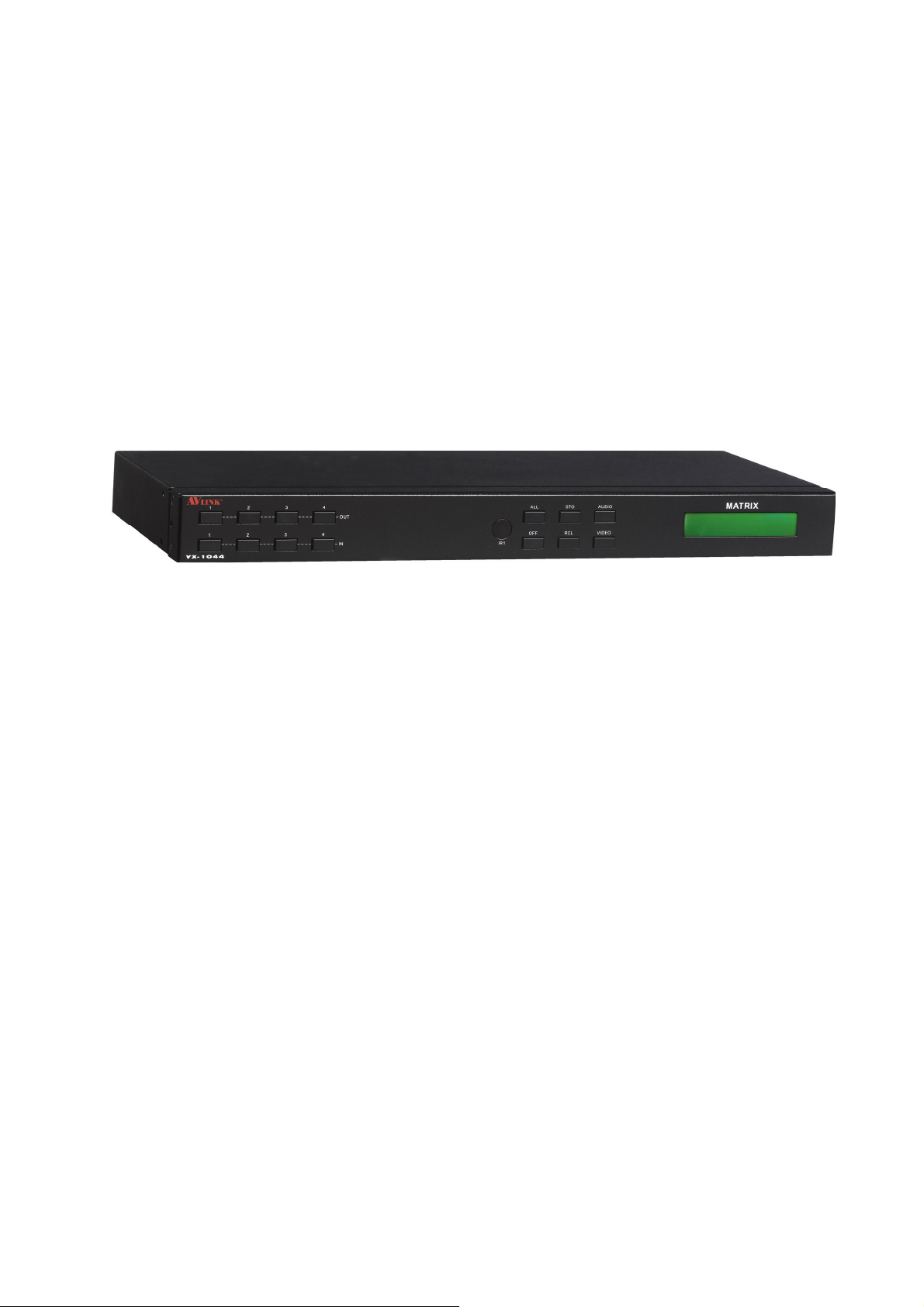
The YX-1044 Matrix switcher is a high performance switching equipment for
audio/video frequencies. It is used for multiple input/output cross switching of audio/video
signals. It provides independent YPbPr component and audio input/output terminals. Each YPbPr
component signal and audio signal is transmitted separately and switched separately, thereby
minimizing signal attenuation and ensuring high definition graphics and high fidelity signal
output.
The YX-1044 Matrix is used mainly in TV broadcasting projects, multi-media conference halls,
large display projects, TV teaching and command control centers.
Figure 1-1 YX-1044 Matrix
3
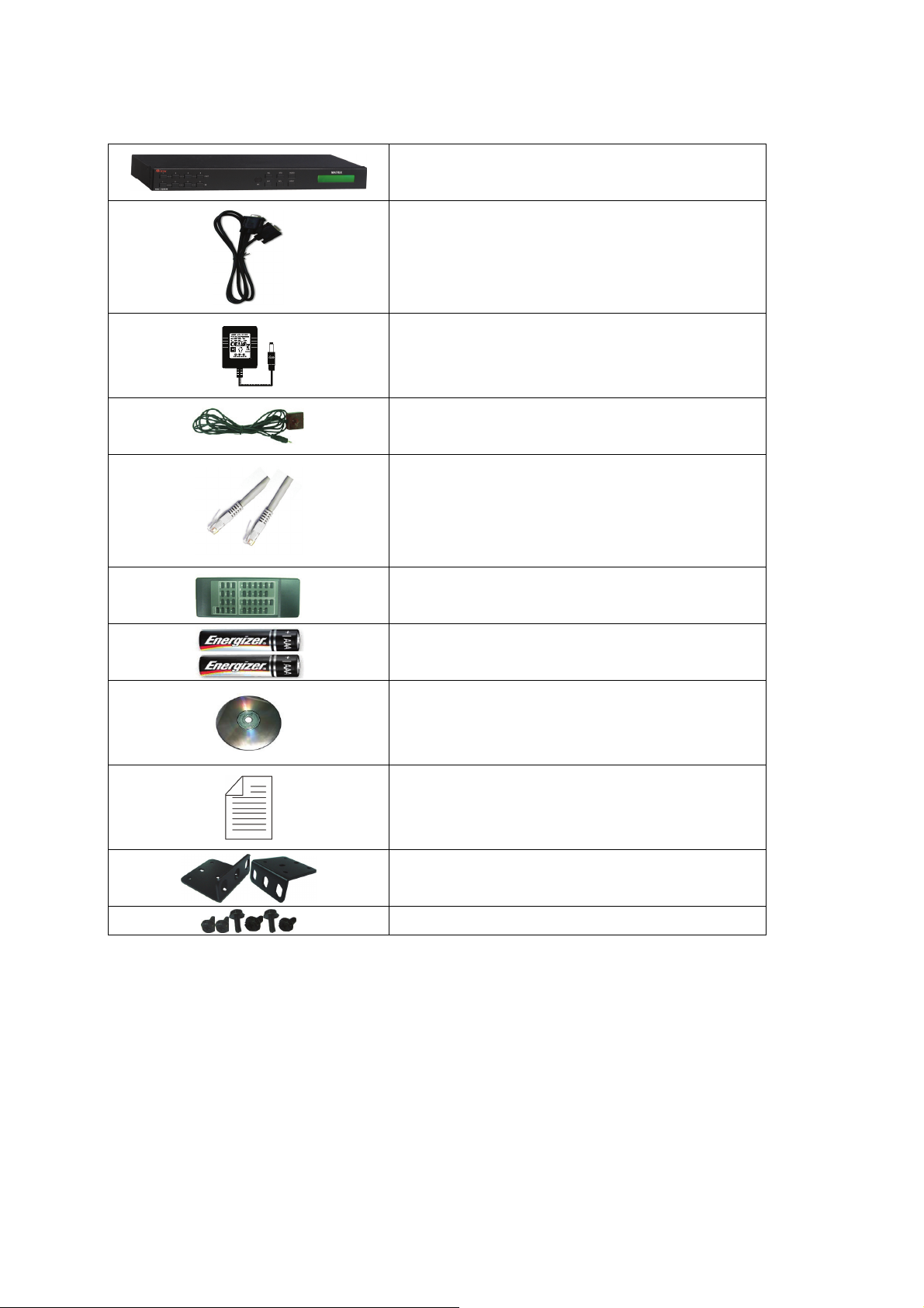
1.0.2 Packing
RS-232 Communication Connecting Cable
YX-1044 Matrix Host
DC12V Power
IR BOX
LAN Line
Controller
2 pcs of AAA battery
HDMI Matrix Software CD
User Manual
2 Rack-Mount Bracket
6 Screws (for Brackets)
4
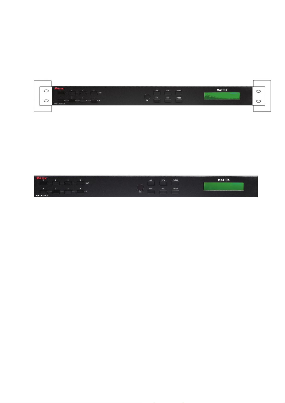
2.0 YX Matrix Host Installation
The YX-1044 Matrix Host has a black metallic housing. It can be placed on a sturdy desk
or installed on a 19-in rack. See Figure 2-1
below:
Figure 2-1 Installing the YX-1044 Matrix Host on a Standard Rack
3.0 YX Matrix System Front/Rear Panels
3.0.1 YX-1044 Front Panels
The YX-1044 Matrix Switching System supports up to 4 Output/Input switching keys on
the Front Panel allow you to switch singal quickly.
There are four kinds of module combinations as below:
Operation method No. 1: “Output Channel”+“Input Channel”.
Click the Output button then click the Input button to set the combinations.
Operation method No. 2: “STO or RCL”+“Output Channel”.
Click the STO or RCL button then click the Output button.
Operation method No. 3: single operation.
This example for EDID button, you can click the EDID button directly.
Operation method No. 4: “STO and RCL”+“Input Channel”.
Click the STO and RCL button then click the Input button to set the combinations.
OUT1~4 keys (output channel): Indicate the Channel 1~Channel 4 for YPbPr and Audio singal
output to peripheral display. You can also use these keys to adjust the status or access the
settings.
IN1~4 keys (input channel): Indicate the Channel 1~Channel 4 for YPbPr and Audio singal
input. You can use these keys to switch to the connection of the connected signal source
channels.
5

IR1: Infrared receiver.
All: This key allows you to set single input channel to all output channels.
- Press the “All” key.
- Select the one of the IN 1~4 keys.
- The selected IN x key will deliver the singal to all output channels.
- You can also press the “All” key and then the “OFF” key to disable all the displayed
switching settings.
OFF: Disable the entire output channels. Press the one of the OUT x keys that you want to
disable the output channel, then press the OFF key. You can also press the “All” button and
then the “OFF” button to disable all the displayed switching settings.
STO: The “Store Key” saves all current input/output corresponding relations.
- Press the “STO” key firstly. (Supports up to 4 sets of memories, you can select the
memory location through OUT1~OUT4).
- Arrang the Output and Input channel combinations (output channel key 1~4).
- The relation between the Output and Input settings will be saved in the memory
permanently.
RCL: The “Retriever Key” retrieves the saved input/output corresponding relations.
- Press the “RCL” key firstly.
- Then make a random to select one of output channel key 1~4.
- The system will retrieve the saved input/output status and implement current staus
switching.
AUDIO: The audio switching selection key switches to another output channel from the same
channel.
Example: Press the Audio key to open or close the Audio switching function. When the LED
indicator next to the Audio key lights shows switching function is open and when the light
goes off shows you have selected to close the audio switching function.
VIDEO: The video switching selection key switches to another output channel from the same
channel.
Example 1:Press the Video key to open or close the video switching function. When the LED
indicator next to the Video key shows video switching function is open and when the light
goes off shows the switching function is close.
LCD: LCD display shows current YPbPr matrix status and operation status.
6
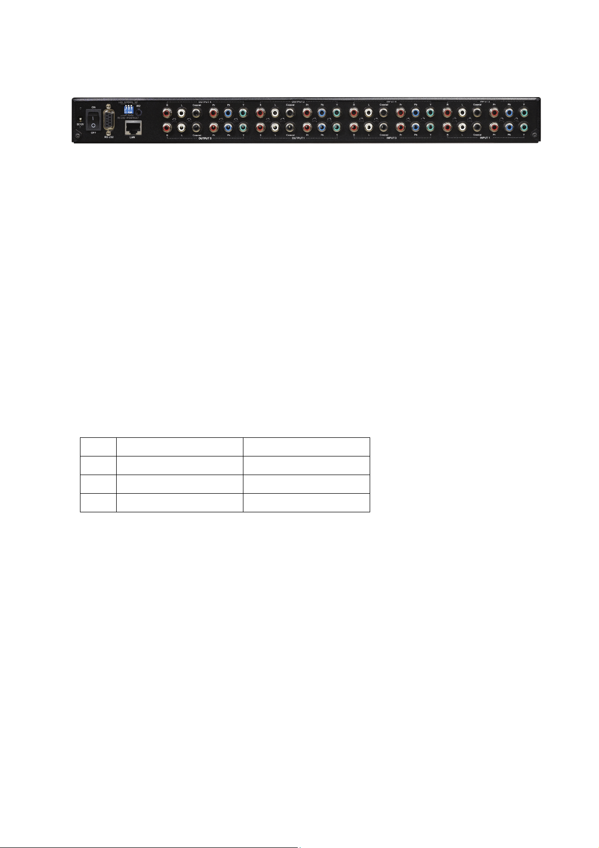
3.0.2 YX-1044 Rear Panels
1. Power Jack
2. Power Switch: To switch power ON or OFF the YX matrix host.
3. RS-232: Use the RS-232 connection cabel to connect the computer serial port (COM1 or
COM2) to the RS232 communication port of the YX matrix host. The computer can then be
used to control the YX matrix after installation of application software. The RS-232 port is a
9-pin female connector.
4. Switcher:
Pin1: Switch between RS-232 port and LAN port connection.
- Pin2: This Pin allows you to reset the IP value to 192.168.0.3. The steps are as below:
a. Please adjust the pin2 down and re-start YX-1044.
b. After the YX-1044 re-starts about 10sec, shut down your equipment.
c. Adjust the pin2 up, then power on YX-1044 again.
d. The IP address will be restored to the default value: 192.168.0.3
- Pin3: No definition.
Pin # UP DOWN
1 LAN RS-232
2 NORMAL IP DEFAULT
3 NC NC
5. LAN Port: Use the RJ-45 connection cable to connect the Internet and the YX matrix host.
The entire PC at the same network can control the YX matrix host through the LAN port.
6. IR2: Connect to the IR BOX.
7. Stereo Unbalanced Audio Output.
8. Digital Optical Audio Output.
9. Video Output.
10. Stereo Unbalanced Audio Input.
11. Digital Optical Audio Input.
12. Video Input.
7
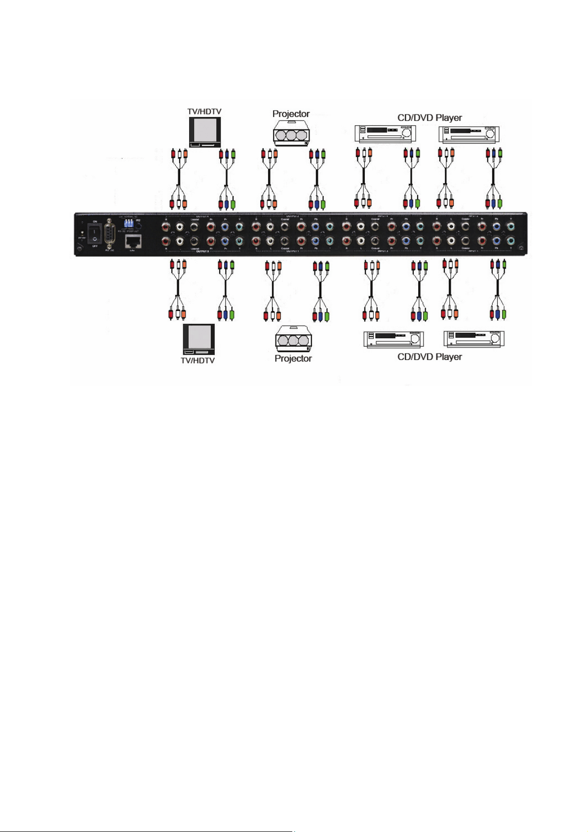
4.0 YX Matrix and Peripherals Connection
Figure 4-1 YX-1044 Matrix System Connection
4.0.1 Input/Output Jacks
The video signal input/output jacks of YX-1044 are formed by the 4th and 2th rows RCA
female connectors. The connectors from top to bottom are: Audio Signal Jack. Y, Pb/Cb,
Pr/Cr.The Y signal jack is green, the Pb/Cb signal jacks are blue, the Pr/Cr signal jacks are red
and the left row audio jacks are red (right audio channel) and the right row audio jacks are white
(left audio channel) and the digital optical module.
Users can connect to different audio/video equipment including CD/DVD players,
graphics workstations, and number display. The output connectors can be connected to projectors,
video recorders, displays and multiplexers.
4.0.2 Audio/Video Connecting Cable
The RCA connecting terminal----audio/video port: The 4-hole RCA Jack is a conventional
audio connector. Its installation hole measures 14x18mm.
YPbPr Connector—Standard Video Input (3-RCA) Connector:
Type: Video connectors are in set (Y, Pb, Pr) (Green Y, Blue Pb, Red Pr)
For YX matrix YPbPr RCA jack connection, see Figure 4-2 below:
8
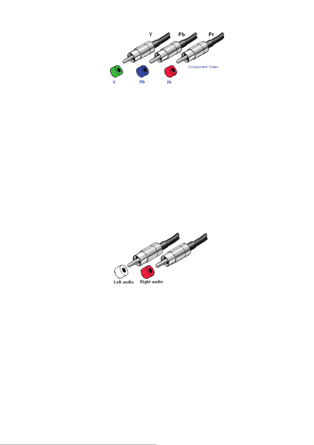
Figure 4-2 YPbPr-RCA Connecting Cables
RCA, an abbreviation for lotus socket, is a DVD component (YpbPr) socket.
The YpbPr connector is a high definition digital TV connector (color contour YpbPr)
capable of connecting with high definition digital set-top box, satellite receiver and various high
definition monitors and TV equipment.
Color difference output (YPbPr) connector separates the modulated Y, PB and PR signals.
It separates the colorimetry C signal into blue b-Y color difference and red r-Y color difference
and uses 3 cables for separate transmission to improve display resolution. This way, it ensures
the largest bandwidth of colorimetry and averts interference to the signals because the signals are
transmitted by 3 separate cables and each cable is being properly sleeved.
The Audio Connecting Cable:
Type: The audio connecting cables are in set for left and right channels (R for red and L for
left).
Connection of the RCA connector of the YX matrix audio is as shown in Figure 4-3 below:
Figure 4-3 AUDIO RCA Connecting Cables
The RCA connector uses coaxial signal transmission with the axial for signal transmission
and the outer ring for grounding. It can be used to transmit digital audio signals and modulated
video signals. Generally, the RCA audio connectors are in pairs separately indicated by red for
the right audio channel (R for right) and black or white for the left audio channel (L for left). The
RCA stereo cable is in one set for both left and right audio channels with each channel in one
cable.
The YX-1044 matrix “Audio Inputs” and “Audio Outputs” can be separately connected to
the audio signal connector of the video recorder and a multiplexer.
Connection Method: Use the RCA (often referred to as the lotus socket) connector for
connection. You are recommended to use the 14 x 18mm 4-hole RCA JAYK connector for
connection to input and output equipment. Connect the RCA video and audio connectors of the
signal source equipment output terminal to the same channel RCA connector of the YX matrix
9

input terminal, and also connect the RCA connectors of the YX-1044 matrix output terminal to
the RCA input connectors of the output equipment via a dedicated RCA signal cable.
NOTE: The RCA connectors at both ends of the various signal cables must correspond to
each other, otherwise loss of color reproduction or even no signal output could happen.
Advantage: The AV connectors have realized separate audio and video transmission,
thereby averted mixed audio/video interference to degrade graphics quality. The AV connectors
have now been extensively used in TV equipment.
5.0 YX Matrix Control Panel Operation
5.0.1 Installation
Before the installation, make sure the peripherals of all DVDs are grounded properly and turned
off.
1. Connect the YX-1044video input RCA connector with RCA Video male to male cable from
DVD players.
2. Connect the YX-1044 audio input RCA connector with RCA audio cable from DVD players.
3. Connect the YX-1044 video output RCA connector with RCA Video male to male cable from
HDTV.
4. Connect the YX-1044 audio output RCA connector with RCA audio cable from HDTV or
audio amplifier.
6.0 YX Matrix / Control Computer Connection
Use the RS-232 connecting cable to connect the computer serial port (COM1 or COM2) to the
RS-232 communication port of the YX matrix host. The computer can then be used to control the
YX matrix after installation of application software. Aside from using the front panel keys for
switching operation, you are also permitted to use the RS-232 connection port for remote
operation.
Figure 6-4 (a) RS-232 and Control PC connection
10

YX-1044 also supports a LAN port allows you to control the equipment host through PC
Browser.
Figure 6-4 (b) LAN port and Control PC Connection
11

The RS-232 Leg functions are described as below:
Pin No. Leg Description
1 N/u Null
2 Tx Send
3 Rx Receive
4 N/u Null
5 Gnd Ground
6 N/u Null
7 N/u Null
8 N/u Null
9 N/u Null
Figure 6-5
Figure 6-5 (a)
12

Figure 6-5 (b)
) The Matrix RS-232 port is defined as DCE.
6.0.1 IR2 Connection
The YX matrix provides you an IR BOX for more convenient to react to the controller. Please
connect the IR BOX to the IR2 port that is on the rear panel.
Figure 6-6 IR Connection
13

7.0 Matrix Application Software
7.0.1 Software Introduction
The 《AV Matrix》 Matrix control software applies to different input/output matrixes.
7.0.2 Software Description
The《AV Matrix》matrix testing software is an application tool developed for matrix testing and
application. The software operation environment is as follows:
Window98/2000/7/NT/XP/Vista/ operatng systems
32M interal memory or above
10M hard disk space or above
CD-ROM
At least one serial communication port
7.0.3 Software Activation
First, you must power off both the YX matrix and the computer. Then, connect the matrix
RS-232 port to the PC RS-232 port with the bundled communication cable. (Refer to the
previous section “YX Matrix and Control Computer Connection”.
Power on the YX matrix and the computer:
Activate the AV Matrix.exe on the bundled CD-ROM in the control computer to enter the
software configuration screen.
14

7.0.4 RS-232 Software Configuration
The software controls signal connection between the corresponding input port and output port as
required. The RS-232 main configuration screen is as below:
Figure 7-1 RS-232 Software Configuration Screen
) YX-1044 is integrated Video/Audio switching equipment; please select the Video check box
before you begin to operate the software.
Scroll on the left area of the main screen to view contents as shown below.
7.0.5 Main Operation Interface Functions
Refer to the window menu above, the interface blue area shows crossing matrix of output
ports 01-04 and input ports 01-04. On the lower right hand corner, you can select either “Video”
for signal input switching or “Disconnect” to close all output ports. Click to check the white box
to the left of “Video” or “Audio” for video or audio signal transmission.
Examples for Selecting Matrix Switching Functions:
Example 1: Now there is a YX-1044 matrix having all the input/output ports properly
15

connected to the equipment. There are two ways of operation if you want to set channel 1
audio/video to channels 2, 3 and channel 3 audio/video to channel 1 for output:
First way: Make sure you have selected“Video” and “Audio” by checking the white boxes to the
left. Directly click on the corresponding icons on the matrix to turn them into
to complete the switching operation.
Second way:
Step 1: Make sure you have selected “Video” and “Audio” by checking the boxes to the left.
Step 2: First select the “Output” number keys 02, 03 and 04 to the right, and select the
“Input” number key 01 to the bottom. Afterwards, press consecutively the previously selected
“Output” number keys 02, 03 and 04 (or you can press the “Deselect all output” key). This way,
you have selected “Input” 01 and “Output” 02, 03 and 04 switching.
Step 3: First select the “Output” number key 01 to the right, and select the “Input” number
key 03 to the bottom. Afterwards, press the previously selected “Output” number key 01 (or you
can press the “Deselect all output” key). This way, you have selected Input 03 and Output 01
switching.
Upon completion of the above 3 steps, you have actually completed the switching operation of
having Audio/Video channel 1 to Output channels 2, 3 and 4 while at the same time successfully
switched from Audio/Video channel 3 to Output channel 1.
Example 2: Now, there is a YX-1044 matrix with the input/output ports properly connected to
the equipment. It is required to set the input/output connectors to switching from video channel 1
to output channels NO.1, 3 and also to switch from audio channel 2 to output channel 4. There
are two ways of operations:
First Way:
Step 1: Make sure you have selected “Video” and not “AUDIO”. Directly click on the icons
on the matrix corresponding to the INPUT number key 01 and the OUTPUT number keys
01、03
to turn into ,you have then selected video switching of input 01 and
output 01,03.
Step 2: Make sure you have selected “AUDIO” and not “Video”. Directly click on the matrix
icons corresponding to INPUT number key 02 and OUTPUT number key 04
to turn
them into ,you have then selected audio switching of input 02 and output 04.
Upon completion of the above 2 steps, you have successfully switched video channel 1 to
output channels 1, 3 and also switched audio channel 2 to output channel 4.
Second Way:
Step 1: Make sure you have selected “Video” and not “AUDIO”.
Step 2: Select the output number keys 01 and 03 to the right and input number key 01 to the
bottom. Afterwards, press consecutively the previously pressed output number keys 01 and 04 to
16

the right (or you can press the Deselect all output key). This way, you have selected video
switching of input 01 to output 01 and 04
Step 3: Make sure you have selected “AUDIO” and not “Video”.
Step 4: Select output number key 04 to the right and input number key 02 to the bottom.
Afterwards, press again the previously-pressed output number key to the right(or you can
press the Deselect all output key). This way, you have selected audio switching of input 02
and output 04.
Upon completion of the above 4 steps, you have completed the operation of switching video
channel 1 to output channels 1 and 3 while also switching audio channel 2 to output channel 4.
7.0.6 Disconnect Function Keys
Disable all the unused output ports.
A specific example of operation is described as below:
The present input and output relations are shown in Figure 7-2 below:
Figure 7-2
First you have to disable the output ports including port 03、02、and 01.
Step 1: First press down the output number keys 03, 02 and 01 to the right of the blue
configuration area.
Step 2: Press the “Disconnect” key.
17

Step 3: Press the previously pressed output number keys 03, 02 and 01 (or press the “Deselect
all output” key) to complete the operation.
Figure 7-3
7.0.7 Select all output, DeSelect all output Switching Functions
(1)Select all output Function Description: You can use this function to select one all output
ports for output to one input port.
A specific example of operation is described below:
Example: Now, you have an YX-1044 matrix with all input and output ports properly connected
to the equipments. The needed input/output ports should be set to channel 1 input to all
output-ports to output
Make sure you have selected the “Video” check box (
output” key and select the input number key 01. Click on the matrix icons along the 01 row
to transform them into to complete the command operation.
(2)DeSelect all output Function Description: It is used to disable the Select all output
function.
). Then, press the “Select all
18

7.0.8 Disconnect all Command
Function Description: To disable all the switching functions. Press the “Disconnect all” key to
disable all the connections of input and output ports.
7.0.9 Memory Function Usage
Function Description: To store and retrieve the settings.
Store Functin Description: The Store Function saves all the present input/output switching
relations to any Locations from #1 to #8 you desired.
A specific example of the Store Function is described below:
Store all the present input/output switching relations to Location #1. First, select Location #1, as
shown in the figure below. Then click the Save key to save all the present input/output switching
relations to Location #1.
Retrieve Function Description: To retrieve the saved input/output switching relations.
A specific example of the Retrieve Function is described below:
To retrieve the input/output corresponding relations saved in Location #1. First, select Location
#1 as shown in the figure below. Then click the Load key to retrieve all the
Input / output corresponding relations stored in Location #1
7.0.10 Scan Function Usage
Use the mouse to click the Scan key to refresh the AV Matrix operating interface.
7.0.11 Options Function Usage
Activation Function:
In the main configuration menu, select Options to prop up the Options Window as shown in
19

Figure 7-4(a)
Figure 7-4(a) Figure 7-4(b)
Function Description:
Linking Methods: In “Port number” select either COM1 port or COM2 port as shown in
Figure 7-4(b); in “Baud rate” select 9600 for signal transmission as shown in Figure 7-4(a)
7.0.12 Exit Function Usage
Function Description: To exit the operating software.
7.0.12 Other Usages
Displays the presently saved switching status as shown in Figure 7-5 below:
Figure 7-5
When Video/Audio corresponding to Output is open, it shows the Output ports
corresponds to the Video/Audio Input ports; when they are close the word None will be shown in
red in the above table.
8.0 Communication Protocol and Control Command Code
Communication Protocol: Baud rate 9600bps, no odd or even calibration bit address, 8bit
transmission address, 1bit stop address.
Refer to the “Command list.pdf” on the CD-ROM for the command system.
20

9.0 LAN Options
9.0.1 LAN Web Configuration
Open the Browser, keyin the default IP address: http://192.168.0.3 to login the AV M AT R I X
Control configuration screen. Once the default IP address is be changed, please use the changed
IP to login.
The software controls signal connection between the corresponding input port and output port as
required. The LAN main configuration screen is as below:
Figure 7-8 LAN Web Configuration Screen
) YX is integrated Video/Audio switching equipment, please only keyin the Output Channel No.
into the Video field, the Audio field value will be a default depends on the Video value
automatically.
Scan: To search the host controlled by the LAN Web Configuration. When the Console List
content is empty, you can click the Scan to research and update the Console List.
Options: Allows you to configure the IP address.
Set: Click this button to set the connected combinations both output and input ports.
Refresh: To refresh the values of the configuration screen. Any changed settings directly on the
YX-1044 equipment will not respond to the AV Matrix operating interface, you have to click the
Refresh button to refresh the configuration screen so that showing the changed values.
OFF: Disable the entire output channels.
STO: The “Store Key” saves all current input/output corresponding relations.
RCL: The “Retriever Key” retrieves the saved input/output corresponding relations.
) For more relatived information, please refer to 5.0.1. Front Panel.
All Output: A Hot Key for you to set the same value to all output channel. Select the All
Output check box, then key in example “2” value in the channel 1 output. Click anywere on the
21

screen, the all channel output will become “2” value.
Figure 7-9
Port Key In: A Hot key that is for key in the Value1~4 quickly.
Reserve and AV Sync: Not be definited for this Model.
Previous and Next: Not be definited for this Model
9.0.2 LAN Main Operation Interface
Refer to the main configuration screen as above, for the basic operation is described as below:
Example: Now there is an YX-1044 matrix having all the input/output ports properly connected
to the equipment. If you want to set channel 1 input to channel 2, 3 and 4 output; channel 3
inputs to channel 1 output.
Figure 7-10
Step 1: For channel 2, 3, 4 Output, please keyin the value “1” in the Video fields.
Step 2: For channel 1 Output, please keyin the value “3” in the Video fields.
Step 3: Click “Set” button.
Upon completion of the above 3 steps, you have actually completed the switching operation of
having channel 1 input to channel 2, 3 and 4 ouput while at the same time successfully switched
from channel 3 input to channel 1 output.
22

9.0.3 LAN Memory Function
Function Description: To store and retrieve the settings.
Store Functin Description (STO): The Store Function saves all the present input/output
switching relations to any Locations from #1 to #8 you desired.
A specific example of the Store Function is described below:
Store the present input/output switching relations to Location #2. First, select Location #2, as
shown in the figure below. Then click the STO button to save the present input/output switching
relations to Location #2.
Retrieve Function Description (RCL): To retrieve the saved input/output switching relations.
A specific example of the Retrieve Function is described below:
To retrieve the input/output corresponding relations saved in Location #1. Select the Location #1
as shown in the figure below. The input/output corresponding relations stored in Location #1 will
be showed directly.
Figure 7-11 Figure 7-12
23

9.0.4 LAN IP Function
Activation Function:
In the main configuration menu, select Options button to prop up the Windows Internet
Explorer dialog box, click “OK” to show the IP configuration screen as shown in Figure 7-11
Figure 7-13
In the Network Settings configuration, you can set the IP information by yourself (Fix IP) or
click the Enable DHCP check box to get the IP from the DHCP (Float IP).
) Click the Default button to restore to default IP address. After changing the IP, you have to
restart (power off then power on) the Host to make the changed values take effectively.
) You can also use the blue Switcher on the rear panel of the Host to reset the ignored IP.
24

9.0.5 Other Application
The software utility will show you at least 32 unit host ID and Name. You can click the Console
down list to select which Host that you want to configure output /input values as Figure 7-14.
The entire connected Host name will be showed on the Console List as Figure 7-15. For this
model, the software utility only shows an ID:00 for the Name: YX-1044 presently.
) When the Console List is empty, please pay attention to the location of switch 1 on the rear
panel of Host is correctly. Then, click Scan to research the configured Host. For YX-1044 model,
only have to make the Console down list value to “00”.
Figure 7-14 Figure 7-15
25

10.0 Operation Examples
Example 1: Switch the NO.1 input signal to the NO.2 output channel.
Key LCD Display Operation
1
1
1
1
2
2
2
2
3
3
3
3
4
OUT
4
IN
4
OUT
4
IN
output channel, then the input
channels will begin to flicker.
2. Press the NO.1 key of the
Input channel.
Example 2: Switch the NO.1 and NO.2 input signals to each NO.1 and NO.2 output channels.
Key LCD Display Operation
1. Press the NO.2 key of the
1
1
2
2
3
3
4
OUT
4
IN
1
1
2
2
3
3
4
OUT
4
IN
1. Press the NO.1 key of the
output channel, then the input
channels will begin to flicker.
2. Press the NO.1 key of the
Input channel.
1
1
2
2
3
3
4
OUT
4
IN
3. Press the NO.2 key of the
output channe, then the input
channels will begin to flicker.
1
1
2
2
3
3
4
OUT
4
IN
4. Press the NO.2 key of the
Input channel.
26

Example 3: Delete “All” settings.
Key LCD Display Operation
1
1
1
1
2
2
2
2
3
3
3
3
4
OUT
4
IN
4
OUT
4
IN
output channel, then the input
channels will begin to flicker.
2. Press the NO.1 key of the
Input channel.
3. Press the ALL key on the
front panel, and then press the
1. Press the NO.2 key of the
OFF key to cancel all the
settings.
27

Example 4: “STO” and “RCL” functions.
Key LCD Display Operation
1
1
1
1
2
2
2
2
3
3
3
3
4
OUT
4
IN
4
OUT
4
IN
output channel, then the
input channels will begin to
flicker.
2. Press the NO.1 key of the
Input channel.
3. Press the STO key on the
front panel. The Store
1. Press the NO.2 key of the
1
1
2
2
3
3
4
OUT
4
IN
Memory begins to flicker
about 8 seconds.
4. Press the NO.1 key of the
output channel to save the
setting in the NO.1
channcel.
5. Press the ALL key on the
front panel, and then press
the OFF key to cancel the
setting.
6. Press the RCL key on the
front panel, The Recall
1
1
2
2
3
3
4
OUT
4
IN
Memory begins to flicker
about 8 seconds.
7. Press the NO.1 key of the
output channel to Load the
previously saving.
28

11.0 YX Matrix System Technical Parameters
Model
Technical Parameters
Video
Enhancement 0dB
Max. Transmission Delay 10nS(±1nS)
Switching Speed 40nS(Longest Time)
Signal Type Component/Composite Video
Video Input Connector 4 Set RCA Female Connectors
Video Input Impedance 75Ω
Video Output Connector 4 Set RCA Female Connectors
Video Output Impedance 75Ω
Audio
Input/Output Connector RCA Female Connectors
Signal Type Stereo, Balanced or Unbalanced, Digital Optical Audio
Specifications
Power Adaptor DC 12V
YX-1044
Operating Temperature 0 ~+85℃℃
Housing Measurements 440(L)x185(W)x43mm(H)
Product Weight 2200g
Median Failure Interval 30,000 Hours
12.0 Common Problems and Solutions
1. What to do if the YX matrix front panel keys switching not responsive?
Answer: The YX matrix front panel keys employ scanning testing and require longer response
time. Press the keys for 2 seconds and then release. This way, key switching will be
responsive in operation.
2. What to do if matrix does not display or color display is abnormal after hot plug?
Answer: Switching of the matrix system goes through the IC chips. If the voltage difference
between the input signal equipment and the matrix equipment is too large, hot plug
could easily cause damage to the IC chips. Please turn off power to the system before
plugging or unplugging.
3. What to do if ghosting happens when YPbPr signals output to display?
Answer: Ghosting is often caused either by the projector, inferior cable quality or long
transmission distance. You are advised to adjust the projector or replace with better
quality cable.
4. What to do if loss of color reproduction happens or no video signal output?
29

Answer: Please check if connectors at both ends of the YPbPr signal cable are correctly
connected.
5. What to do if the corresponding graphics fail to output during YX matrix switching?
Answer: (1) Check if there is signal on the input end. If there is no input signal, it could be that
the input connection cable is broken or the connector gets loosen. You are advised to
replace the connection cable.
(2) Check if there is signal on the output end. If there is no output signal, it could be that
the cable is broken or the connector gets loosen. You are advised to replace the
connection cable.
(3) Check if the output port number is the same as the controlled port number.
(4) If none of the above circumstances happen, it could be internal failure of the product
itself. You must send for repair by qualified technical engineers.
6. What to do if the power LED is not on, LCD has no display and no response in operation?
Answer: Check if the equipment power input is in good contact.
7. What to do if you sensed power leakage during plugging or unplugging of the audio/video
ports?
Answer: It could be that the equipment power is not properly grounded. You must properly
ground your equipment, otherwise product life can easily be shortened.
8. What to do if the YX matrix panel keys and communication ports are out of order?
Answer: Check if the equipment power input is in good contact and the computer
communication ports are in good order. If yes, it could be some internal failure of the
product, please send for repair by qualified technical engineer.
9. What to do if operation and function failure occurred?
Answer: Check if the equipment and the matrix system are in proper connection. If the problem
persists, send the product to the maintenance center for repair.
NOTE:
Do not replace the power cord yourself. If the power cord is damaged, ask your distributor to
send qualified technician to replace it for you.
© C&C TECHNIC TAIWAN CO., LTD. All rights reserved.
Trademarks:
All the companies, brand names, and product names referred to this manual are the
trademarks or registered trademarks belonging to their respective companies.
30
 Loading...