

Page 1
VIDEO/AUDIO
Selector
VRM-714FAE
USER MANUAL V1.1
VRM-714FAE
Package Contents-
1 AVLINK VRM-714FAE
1 user manual
1 power adapter DC 12V/600mA
1 IR remote controller
2 rack rails, 8 screws
If anything is missing, please contact your vendor.
Features
Extends the video/audio signal up to 300 meter.
Supports VGA, SVGA, UXGA, QXGA resolutions.
Supports audio stereo unbalanced.
Audio sample rate 96 KHz.
Can use an external microphone to output sounds to
the audio amplifier.
Remote controller for operation.
Auto skips over the power-off and suspended PC and
the unplugged VGA cable.
1U rack design.
Specifications
Function VRM-714FAE
VGA Input Connector 4x HD-15 Female
Audio Input Connector 4x 3.5φ Mini-Stereo Jack
MIC Input Connector 4x 3.5φ Mini-Stereo Jack
Video/Audio Output
Connector
LEDs
Select Switch 4
Cable Distance 300 m (Max.)
Max. Resolution 1280x1024 60Hz
Power Adapter (Min.) DC 12V 600mA
Housing Metal
Dimensions (LxWxH) 269x106x42mm
On Line 4
Selected 4
Weight 1055g
Technical Specifications
Input/Output Signal
Pin # Signal
1 Red video 9 NC
2 Green video 10 Ground
3 Blue video 11 ID0
4 ID2 12 ID1
5 Ground 13 Horizontal sync
6 Analog ground 14 Vertical sync
7 Analog ground 15 ID3
8 Analog ground
1x RJ-45 Female
Pin # Signal
-1-
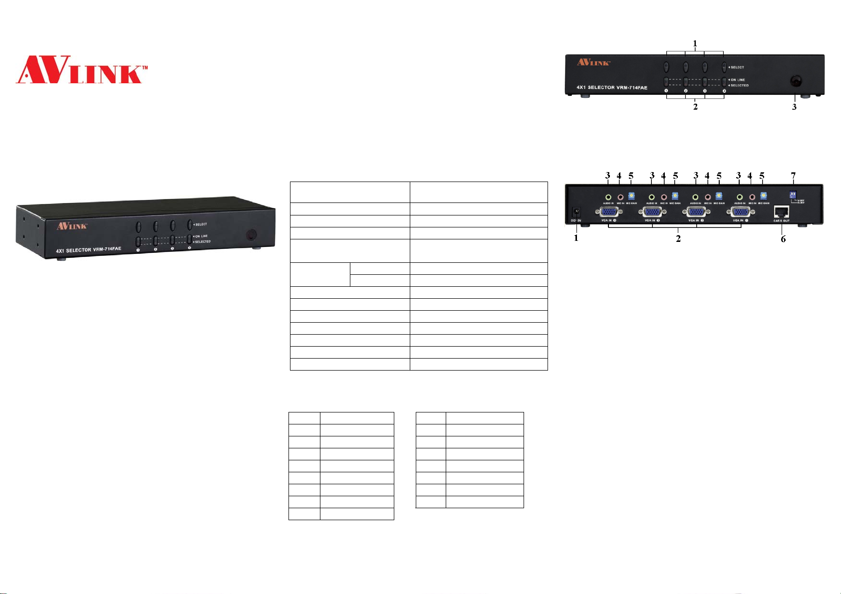
FRONT VIEW
1. Push-button Switches (Manual type)
2. Port LEDs
3. IR Receiver
REAR VIEW
1. Input Power Jack
2. Video Input
3. Audio Input
4. MIC Input
5. MIC GAIN – adjust volume of microphone
6. RJ-45
7. Control H/V signal inverting switch
If the H/V signal is negative logic, then you need to
Output
The default setting of SW1 is “OFF”. If SW1 is set to
“ON”, the H signal is inverting output.
The default setting of SW2 is “OFF”. If SW2 is set to
“ON”, the V signal is inverting output.
change the logic of the H/V signal or if you have any
other problems, please use this function.
-2-
Page 2
Installation
Before the installation, make sure the peripherals of all PCs
are grounded properly and turned off.
1. Connect the VRM-714FAE HD-15 female input
connector with the HD-15 male to the male cable from
the PCs.
2. Connect the VRM-714FAE audio input connector with
the audio cable from the PCs.
3. Connect the VRM-714FAE mic input connector with the
mic cable from microphone.
4. Connect the VRM-714FAE RJ-45 output connector and
the AV-Extender remote unit RJ-45 input connector with
the CAT.5 cable.
5. Connect the power adapter on each side.
6. The red LED’s will flash on port 1. If not, please go back
to check step 5.
7. Turn on the PCs, the monitor and the audio amplifier.
8. The green on line LED lights up, while the PC has been
connected properly with the corresponding port, and is
up and running.
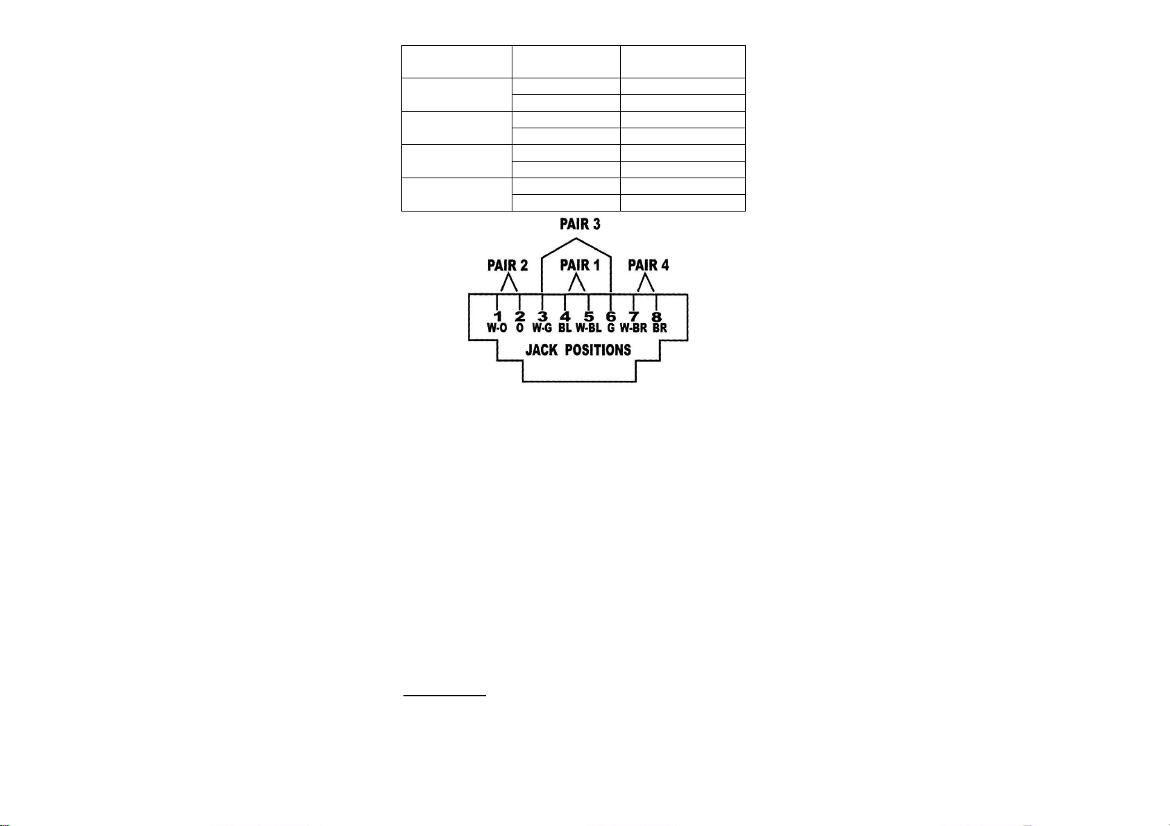
Wiring Information & Coding
Conductor
Identification
Pair 1
Pair 2
Pair 3
Pair 4
RJ45 Pin
Assignment
5 White-Blue
4 Blue
1 White-Orange
2 Orange
3 White-Green
6 Green
7 White-Brown
8 Brown
Color Code for
Conductor
Operation
1. Port selection
Press the button of “port selection switch” to access
the desired PC.
The selected corresponding port will light up for the
red LED’s which indicate the port is activated.
2. IR remote control
Use the “1”, ”2”, “3”, ”4” keys to select the desired
PC.
Use the “
Use the ”SCAN MODE” key to enable/disable Auto
Scan function.
Auto Scan time can be increased progressively from
every 5 seconds to 30 seconds by using the “▲” key.
Conversely, use the “▼” key to decrease the time from
30 seconds to 5 seconds.
While Auto Scan function is applied, port selection
keys will not work.
”, “▼” keys to select another PC.
▲
-3-
© C&C TECHNIC TAIWAN CO., LTD. All rights reserved.
Trademarks:
All the companies, brand names, and product names
referred to this manual are the trademarks or registered
trademarks belonging to their respective companies.
-4-
 Loading...