

Page 1
HDMI
EXTENDER
VH-ELWB
(Local)
VH-ERWB
(Remote)
USER MANUAL V1.0
VH-EXWB
Package Contents-
1x VH-ELWB Local Unit
1x VH-ERWB Remote Unit
1 user manual
1x Power adapter DC 48V with lock and Power Cord
1x IR Blaster Cable
1x IR Receiver Cable
4x screws
8x foot pads
2x Female 1x2 Pole Captive Screw Socket
Any thing missed, please contact with your vendor.
Features
Through the HDMI Extender, you can use one DVD or
PC to display identical image and extension of HDMI
signal up to 100 meter on HDTV
HDCP Compliant
Supports 3D pass-through
Support RS-232(Bi-direction transfer)
Supports all frequency band IR control
One CAT.5 cable extension
Supports HDTV up to 4k2k
Supports VGA up to 1920 X1200
HD-baseT technology
Use CAT.5 cable to install easily
Cable Distance
Supports Power over Cable
Undervoltage, Overvoltage and Thermal Protection
Short-Circuit Protection with Auto-Restart
Resolution Cable Type
1080P(12bit)
4Kx2K
Cat5e/Cat6
Cat6a/Cat7
Cat5e/Cat6
Cat6a/Cat7
VH-EXWB
100M
100M
70M
100M
Specifications
Function Local Remote
HDMI In Connector
HDMI Out Connector
VGA In Connector HD-15 Female x 1
RJ-45 Connector 1
IR OUT 3.5ψ Stereo Jack x 1
IR2 IN 3.5ψ Stereo Jack x 1
Source select
(TAC Switch)
Source select (TB) 1X2 Pole Captive Screw
Max. Resolution 4k2k
FW Upgrade Switch
Mode select Switch
Cable Distance 100M
Power Adapter (Min.)
Housing Metal
Weight 550g 324g
Dimensions (LxWxH) 171x120x35 mm 150x80x35 mm
HDMI A-Type
Female x 1
HDMI A-Type
Femalex1(DA)
TAC SW X1
8 PIN DIP Switch
DC 48V with lock
-1-
None
HDMI A-Type
Female x 1
2 PIN DIP Switch
None
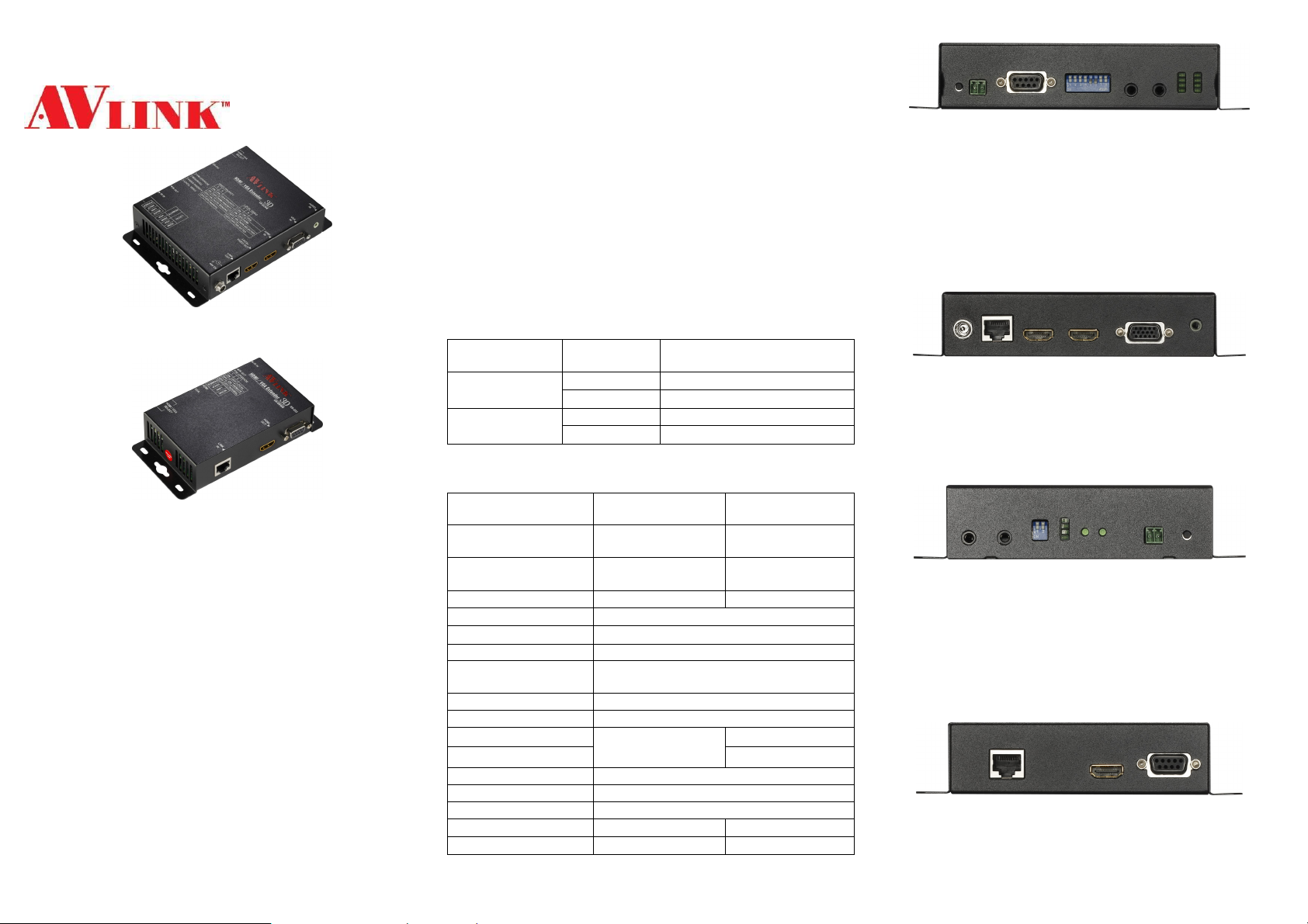
LOCAL FRONT VIEW
1. TACK SW (HDMI/VGA SELECT)
2. 1X2 Pole Captive Screw (HDMI/VGA SELECT)
3. RS-232
4. DIP SW
5. IR OUT
6. IR IN
7. SOURCE LED (LOCAL HDMI / VGA, REMOTE HDMI
/ VGA)
8. ACTIVE LED (MODE, LINK, HDCP, POWER)
LOCAL REAR VIEW
1. Power jack (48V DC IN)
2. LINK (RJ-45 Connector)
3. HDMI OUT (DA)
4. HDMI IN
5. VGA IN
6. AUDIO IN
REMOTE FRONT VIEW
1. IR IN
2. IR OUT
3. DIP SW
4. ACTIVE LED (MODE, LINK, HDCP, POWER)
5. HDMI LED
6. VGA LED
7. 1X2 Pole Captive Screw (HDMI/VGA SELECT)
8. TACK SW (HDMI/VGA SELECT)
REMOTE REAR VIEW
1. LINK (RJ-45 Connector)
2. HDMI OUT
3. RS-232
-2-
Page 2
Installation
Pin #
Signal
Pin #
Signal
Conductor
RJ45 Pin
Color Code for
1. Turn off the DVD PC and HDTV.
2. Connect the HDMI extension cable between the DVD
and the “HDMI IN” port of VH-ELWB.
3. Connect the VGA extension cable between the PC and
the “VGA IN” port of VH-ELWB.
4. Connect the AUDIO extension cable between the PC
and the “AUDIO IN” port of VH-ELWB.
5. Connect the HDMI extension cable between the HDTV
and the “HDMI OUT” port of VH-ELWB.
6. Connect the CAT.5 cables between the VH-ELWB
“LINK” port and the VH-ERWB “LINK” port of extender.
7. Connect the power cord and turn on the extender.
8. Turn on the DVD and HDTV.
9. Select source (HDMI/VGA) by TACK SW or 1X2 pole
captive screw (short).
IR Receiver Cable Directions:
Put it into the VH-ERWB “IR IN” port and place the IR
Receiver Cable, so that you can point to it easily with your
IR remote controller.
IR Blaster Cable Directions:
Plug IR blaster cable plug into VH-ELWB “IR OUT” port, It
sits in front of the DVD receiver’s IR sensor, which is
located on the front-panel.
DIP Switch Setting
VH-ELWB:
BIT 1~2: F/W UPGRADE
OFF, OFF NORMAL
OFF, ON REMOTE
ON, OFF LOCAL
BIT 5~6: AUTO/MANUAL
OFF, OFF NORMAL
OFF, ON AUTO SENSING
ON, OFF HDMI PRIORITY
ON, ON VGA PRIORITY
BIT 7~8: DA MODE
OFF, OFF SELECTED
OFF, ON NON-SELECTED
ON, OFF HDMI
ON, ON VGA
VH-ERWB:
BIT 1~2: F/W UPGRADE
OFF, OFF NORMAL
OFF, ON LOCAL
ON, OFF REMOTE
-3-
F/W UPGRADE
Process the Update TX_xxx.bat or UpdateRX_xxx.bat file
to upgrade firmware. (xxx is specified for firmware version)
These files are used for upgrading in your devices.
- The UpdateTX_xxx.bat file is used to upgrade the
Local firmware.
- The UpdateRX_xxx.bat file is used to upgrade the
Remote firmware.
Local Unit:
1. Connect the RS-232 cable between the PC and the
“RS-232” port of VH-ELWB.
2. Dip switch bit1 set “ON’, Running “TX_xxx.bat” file ,you
can upgrade VH-ELWB.
3. Dip switch bit2 set “ON’, Running “RX_xxx.bat” file ,you
can upgrade VH-ERWB.
Remote Unit:
1. Connect the RS-232 cable between the PC and the
“RS-232” port of VH-ERWB.
2. Dip switch bit1 set “ON’, Running “RX_xxx.bat” file ,you
can upgrade VH-ERWB.
3. Dip switch bit2 set “ON’, Running “TX_xxx.bat” file ,you
can upgrade VH-ELWB.
Additional Options
Select any additional options you may require.
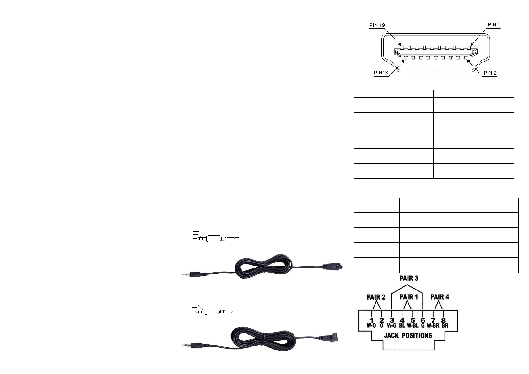
1. IR Receiver Cable
GND
+V
Sig
2. IR Blaster Cable
NC
P+
N-
-4-
Technical Specifications Output Signal
TMDS Data 2+
1
TMDS Data 2 Shield
2
TMDS Data 2-
3
TMDS Data 1+
4
TMDS Data 1 Shield
5
TMDS Data 1-
6
TMDS Data 0+
7
TMDS Data 0 Shield
8
TMDS Data 0-
9
TMDS Clock+
10
TMDS Clock Shield
11
TMDS Clock -
12
CEC
13
Reserved
14
(N.C. on device)
SCL
15
SDA
16
DDC/CEC Ground
17
+5 Power
18
Hot Plug Detect
19
Wiring Information & Coding
Identification
Pair 1
Pair 2
Pair 3
Pair 4
Assignment
5 White-Blue
4 Blue
1 White-Orange
2 Orange
3 White-Green
6 Green
7 White-Brown
8 Brown
-5-
Conductor
Page 3

Support VGA mode
Trademarks:
Analog Resolution Frequency(Hz)
VGA 640x480 60 / 72 / 75 / 85
VGA 720x400 70 / 85
SVGA 800x600 56 / 60 / 72 / 75 / 85
WVGA 848x480 60
XGA 1024x768 60 / 70 / 75 / 85
SXGA 1152x864 75
SXGA 1280x768 60RB / 60 / 75 / 85
WXGA 1280x800 60
SXGA 1280x960 60 / 85
SXGA 1280x1024 60 / 75 / 85
WXGA 1360x768 60
SXGA+ 1400x1050 60RB / 75
WXGA+ 1440x900 60
SXGA+ 1440x1050 60
UXGA 1600x1200 60
WSXGA+ 1680x1050 60
1080P 1920x1080 60
WUXGA 1920x1200 60RB
720P 1280x720 60
Note
However sometimes, especially in demonstrations or in a
lab environment, the cable is rolled randomly in small turns
for convenience. The randomly rolled UTP cable suffers
additional signal impairments (compared to a straight cable)
and therefore the maximal operating reach might be
reduced.
Rolling a CAT5E cable around a 70cm fixed diameter
plastic drum has just a minor effect on the FEXT (Far End
Cross Talk) when compared to a fully stretched
cable.
]
© C&C TECHNIC TAIWAN CO., LTD. All rights reserved.
-6-
All the companies, brand names, and product names
referred to this manual are the trademarks or registered
trademarks belonging to their respective companies.
-7-
 Loading...