

Page 1
DVI
EXTENDER
(Support EDID copy)
DVI-LD
(Local)
DVI-R
(Remote)
USER MANUAL V1.2
DVI-ED
Package Contents-
DVI Extender Local Unit
DVI Extender Remote Unit
1 user manual
2 power adapter DC 5V 1A
Anything missed, please contact with your vendor.
Introduction
The extension of DVI-ED video signal device up to 30/50
meter away by using DVI extender and one CAT.5 cable,
and it support “EDID COPY” ability. The DVI-LD can read
and remember the EDID of your monitor by you push
“EDID COPY” button. Make the PC send out the beat
resolution to match monitor for your application.
DVI extender is ideal for:
Test bench facilities
Data Center
Help desks
Features
PC resolution to 1600x1200 60Hz / 30 meter.
PC resolution to 1280x1024 60Hz / 50 meter.
Support DVI-D.
Support EDID copy.
Use CAT.5 cable to install easily.
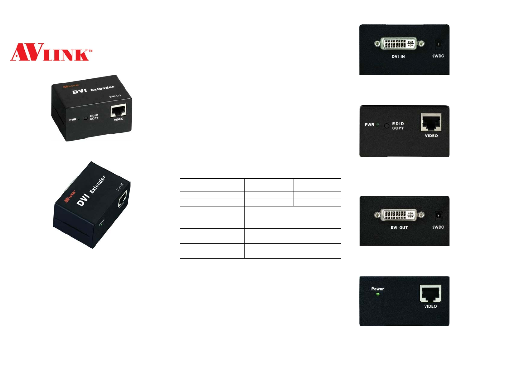
Specifications
Function DVI-LD
Input Connector 1 DVI Female 1 RJ-45 Female
Output Connector 1 RJ-45 Female 1 DVI Female
Max. Resolution
Cable Distance 30/50 m (Max.)
Power Adapt er (Min.) DC 5V 1A
Housing Metal
Weight 141g
Dimensions (LxWxH) 67x52x38 mm
-1-
1600x1200 60Hz /
1280x1024 60Hz
DVI-R
LOCAL FRONT VIEW
1. “DVI In” Port
2. Power Jack
LOCAL REAR VIEW
1. Power LED
2. “EDID COPY” Button
3. “CAT.5” Port
REMOTE FRONT VIEW
1. “DVI Out” Port
2. Power Jack
REMOTE REAR VIEW
1. Power LED
2. “CAT.5” Port
-2-
Page 2
Installation
1. Turn off the PC and monitor.
2. Plug the 5V power supply into the DVI-LD and DVI-R.
3. Turn on the monitor, and connect monitor to the “DVI In”
port on the DVI-LD with DVI cable.
4. Push “EDID COPY” button had completed EDID
read/Write after LED flash 3 times.
5. Remove the monitor cable from the DVI-LD and plug in
the “DVI Out” port
on the DVI-R.
6. Connect the CAT.5 cable between the DVI-LD “CAT.5”
port and the DVI-R “CAT.5” port of extender.
7. Turn on the PC.
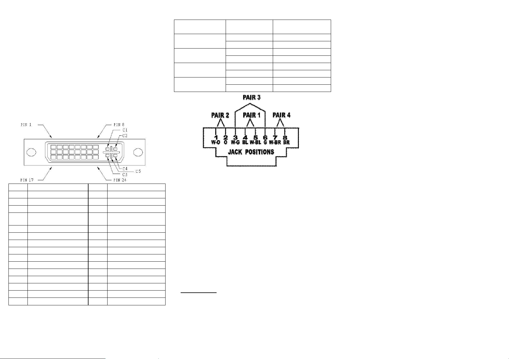
Technical Specifications
Input/Output Signal
Wiring Information & Coding
Conductor
Identification
Pair 1
Pair 2
Pair 3
Pair 4
RJ45 Pin
Assignment
Color Code for
Conductor
5 White-Blue
4 Blue
1 White-Orange
2 Orange
3 White-Green
6 Green
7 White-Brown
8 Brown
Pin # Signal Pin # Signal
T.M.D.S Data 2-
1
T.M.D.S Data 2+
2
T.M.D.S Data 2/4 Shield
3
T.M.D.S Data 4-
4
T.M.D.S Data 4+
5
DDC Clock
6
DDC Data
7
Analog Vert. Sync
8
T.M.D.S Data 1-
9
T.M.D.S Data 1+
10
T.M.D.S Data 1/3 Shield
11
T.M.D.S Data 3-
12
T.M.D.S Data 3+
13
+5V Power
14
GND
15
Hot Plug Detect
16
T.M.D.S Data 0-
17
T.M.D.S Data 0+
18
T.M.D.S Data 0/5
19
Shield
T.M.D.S Data 5-
20
T.M.D.S Data 5+
21
T.M.D.S Clock Shield
22
T.M.D.S Clock+
23
T.M.D.S Clock-
24
Analog Red
C1
Analog Green
C2
Analog Blue
C3
Analog Horz Sync
C4
Analog Ground
C5
-3-
© C&C TECHNIC TAIWAN CO., LTD. All rights reserved.
Trademarks:
All the companies, brand names, and product names
referred to this manual are the trademarks or
registered trademarks belonging to their respective
companies.
-4-
 Loading...