

Page 1
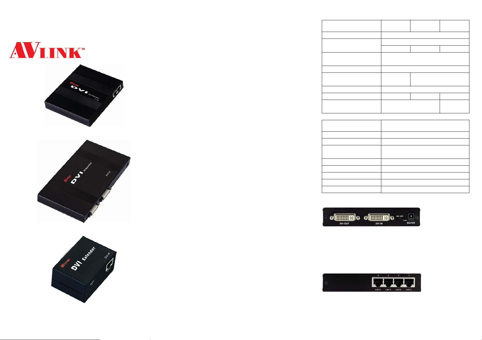
DVI
EXTENDER
(Support EDID copy)
DVI-E2 / DVI-E4
DVI-E8
DVI-R
USER MANUAL V1.0
Package Contents for DVI-E2
1 AVLINK DVI-E2 (Local Unit)
1 user manual
1 power adapter DC 12V/600mA
Package Contents for DVI-E4
1 AVLINK DVI-E4 (Local Unit)
1 user manual
1 power adapter DC 12V/1.25A
Package Contents for DVI-E8
1 AVLINK DVI-E8 (Local Unit)
1 user manual
1 power adapter DC 12V/1.25A
Package Contents for DVI-R
1 AVLINK DIV -R (Remote Unit)
1 user manual
1 power adapter DC 5V 1A
Any thing missed, please contact with your vendor.
Introduction
Use 1 PC to display identical image and extension of
DVI-D video signal up to 30/50 meter on 2, 4, 8 monitors.
DVI-E2/DVI-E4/DVI-E8 were used with DVI-R extender
and 2, 4, 8 CAT.5 cable.
DVI extender is ideal for:
Test bench facilities
Data Center
Help desks
Features
PC resolution to 1600x1200 60Hz / 30 meter.
PC resolution to 1280x1024 60Hz / 50 meter.
DVI port can read and transmit EDID.
Support DVI-D.
Use CAT.5 ca ble to install easily.
-1-
Specifications
Function DVI-E2 DVI-E4 DVI-E8
Input Connector 1 DVI Female
Output Connector
Max. Resolution
Cable Distance 30/50 m (Max.)
Power Adapter (Min.)
Housing Aluminum
Weight 230g 247g 345g
Dimensions (LxWxH) 130x111x29.5 mm
Function DVI-R
Input Connector 1 RJ-45 Female
Output Connector 1 DVI Female
Max. Resolution
Cable Distance 30/50 m (Max.)
Power Adapt er (Min.) DC 5V 1A
Housing Metal
Weight 141g
Dimensions (LxWxH) 67x52x38 mm
2 RJ-45 4 RJ-45 8 RJ-45
DC 12V
600mA
DVI-E2/DVI-E4 FRONT VIEW
1. “DVI Out” Port
2. “DVI In” Port
3. “DDC COPY” Button
4. Power LED
5. Power Jack
DVI-E2/DVI-E4 REAR VIEW
1. “CAT.5” Port
1 DVI Female
1600x1200 60Hz /
1280x1024 60Hz
DC 12V 1.25A
200x111
x29.5 mm
1600x1200 60Hz /
1280x1024 60Hz
-2-
Page 2
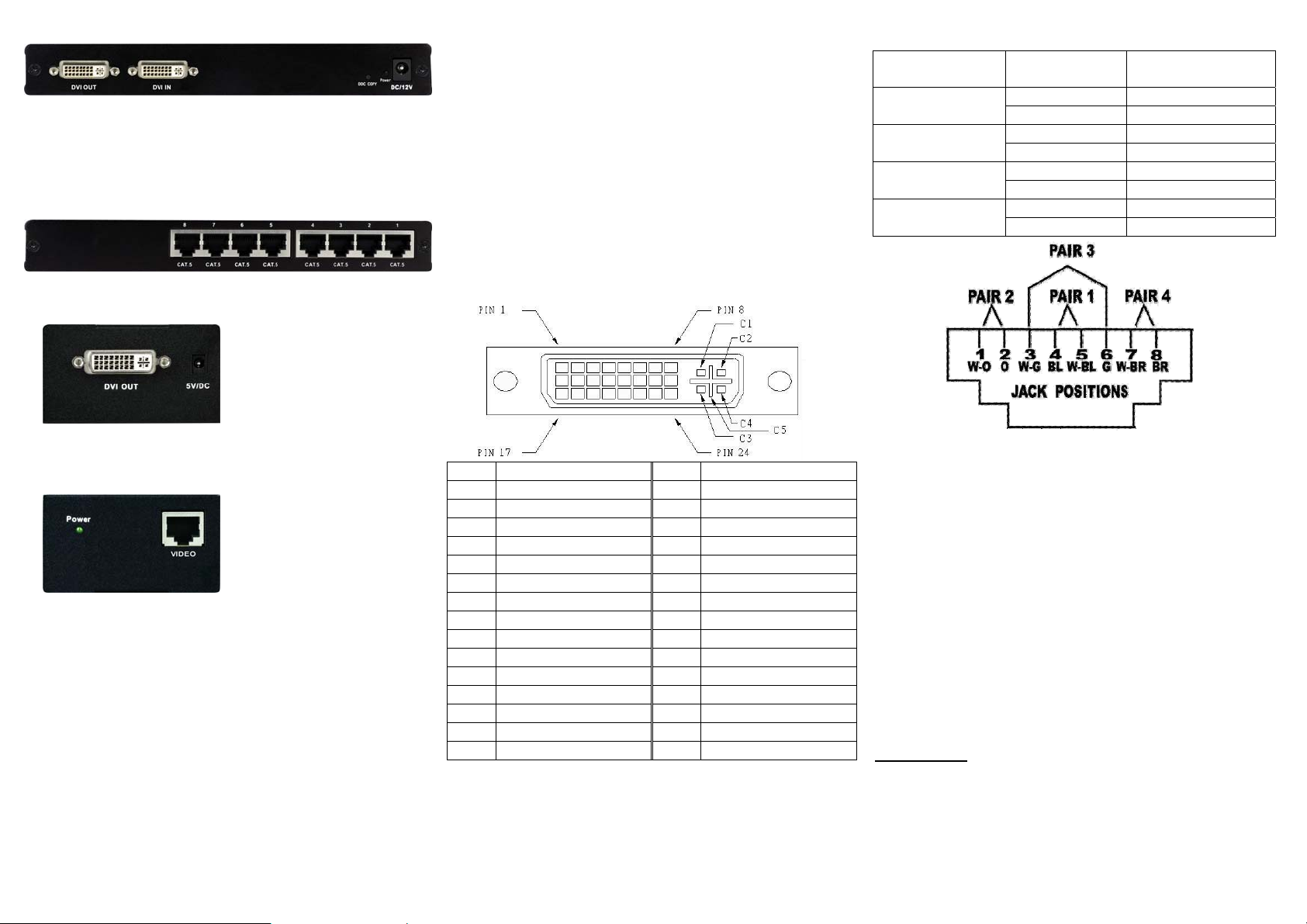
DVI-E8 FRONT VIEW
1. “DVI Out” Port
2. “DVI In” Port
3. “DDC COPY” Button
4. Power LED
5. Power Jack
DVI-E8 REAR VIEW
1. “CAT.5” Port
DVI-R FRONT VIEW
Installation steps:
1. Turn off the PC and monitor.
2. Connect the DVI male/male extension cable between
the PC and the “DVI In” port of DVI-E2 or DVI-E4 or
DVI-E8.
3. Connect the DVI male/male extension cable between
the monitor and the “DVI Out” port of DVI-R.
4. Connect the CAT.5 cable between the DVI-E2 or DVI-E4
or DVI-E8 “CAT.5” port and the DVI-R “CAT.5” port of
extender.
5. Connect the power adapter to turn on the extender.
6. Turn on the PC and monitor.
Technical Specifications
Input/Output Signal
Wiring Information & Coding
Conductor
Identification
Pair 1
Pair 2
Pair 3
Pair 4
RJ45 Pin
Assignment
5 White-Blue
4 Blue
1 White-Orange
2 Orange
3 White-Green
6 Green
7 White-Brown
8 Brown
Color Code for
Conductor
1. “DVI Out” Port
2. Power Jack
DVI-R REAR VIEW
1. Power LED“
2. CAT.5” Port
Installation
Before the installation:
When using it at the first time, you need to do the “EDID
data copy” action.
1. Connect the DVI male/male extension cable between
the monitor and the “DVI Out” port of DVI-E2 or DVI-E4
or DVI-E8.
2. Connect the power adapter to turn on the extender.
3. Turn on the monitor.
4. Pres s “DDC COPY” button to complete EDID
Read/Write action, then the Power LED will flash 3 times
and constant light.
-3-
Pin # Signal Pin # Signal
T.M.D.S Data 2-
1
T.M.D.S Data 2+
2
T.M.D.S Data 2/4 Shield
3
T.M.D.S Data 4-
4
T.M.D.S Data 4+
5
DDC Clock
6
DDC Data
7
Analog Vert. Sync
8
T.M.D.S Data 1-
9
T.M.D.S Data 1+
10
T.M.D.S Data 1/3 Shield
11
T.M.D.S Data 3-
12
T.M.D.S Data 3+
13
+5V Power
14
GND
15
Hot Plug Detect
16
T.M.D.S Data 0-
17
T.M.D.S Data 0+
18
T.M.D.S Data 0/5 Shield
19
T.M.D.S Data 5-
20
T.M.D.S Data 5+
21
T.M.D.S Clock Shield
22
T.M.D.S Clock+
23
T.M.D.S Clock-
24
Analog Red
C1
Analog Green
C2
Analog Blue
C3
Analog Horz Sync
C4
Analog Ground
C5
-4-
© C&C TECHNIC TAIWAN CO., LTD. All rights reserved.
Trademarks:
All the companies, brand names, and product names
referred to this manual are the trademarks or
registered trademarks belonging to their respective
companies.
-5-
 Loading...