

Page 1
User Manual
CX-2044 CX-2084
CX-2088
CX Series Matrix Switching System
Page 2

CX Matrix Switching System—User Manual
Before You Use the System
1、Read manual——Carefully read the manual before you use the system.
2、Installation environment——The system should be installed indoor only. Install either on a
sturday rack or desk in a well-ventilated place.
3、Lightning——Unplug the power cord during lightning or after a prolonged period of non-use
to avoid damage to the equipment.
4、Maintenance——Only qualified technical engineers or specified distributors are permitted to
repair or replace components and parts of the equipment upon failure.
1
Page 3

CX Matrix Switching System—User Manual
Table of Contents
1.0 Matrix System Overview…………………………………….……………………….4
1.0.1 CX Matrix System……………………………………………………………….4
1.0.2 CX Matrix System Packing……………………………………………………...4
2.0 CX Matrix Host Installation………………………………………………………….5
3.0 CX Matrix System Categories……………………………………………………......6
4.0 Matrix System Front and Rear Panel…………………………………………………6
4.0.1 CX-2044 Front and Rear Panel..............................................................................6
4.0.2 CX-2084 Front and Rear Panel………………………………………………......7
4.0.3 CX-2088 Front and Rear Panel……………………………………………..........7
5.0 CX Matrix System and Perpherals Connection………………………………….……8
5.0.1 Input/Output Ports………………………………………………………………..8
5.0.1.1 Audio/Video Connecting Cable…………………………………………..….8
5.0.2 CX Matrix System and Computer Connection………………………………….10
5.0.3 Remote Control and Settings…………………………………………………....10
5.0.3.1 RS-232 Communication Port and Connection……………………………..10
5.0.3.2 RS-485 Communication Port……………………………………………….10
5.0.3.3 On/Off Switches…………………………………………………………….13
5.0.3.4 CX Matrix System and Control System Connection……………………….15
6.0 Matrix System Control Panel Operation……………………………………………..17
6.0.1 Input/Output Switching Key Operating Mode…………………………………..17
6.0.2 Front Panel Key Functions………………………………………………………17
6.0.3 Operation Examples……………………………………………………………..19
7.0 Matrix Application Software…………………………………………………………21
7.0.1 Software Introduction……………………………………………………………21
7.0.1.1 Software Description………………………………………………………..21
7.0.1.2 Software Activation…………………………………………………………22
7.0.2 Software Features………………………………………………………………..22
7.0.2.1 Main Operating Interface Features………………………………………….22
7.0.2.2 Disconnect Function Key…………………………………………………...24
7.0.2.3 Select all output、DeSelect all output Switching Function Usage…………25
7.0.2.4 Disconnect all Commands…………………………………………………..26
7.0.2.5 Memory Function Usage……………………………………………………26
7.0.2.6 Scan Function Usage………………………………………………………..26
7.0.2.7 Options Function Applications……………………………………………...26
7.0.2.8 Exit Function Applications………………………………………………….27
7.0.2.9 Other Applications…………………………………………………………..27
8.0 Communication Protocol and Control Command Code……………………………...27
2
Page 4

CX Matrix Switching System—User Manual
9.0 CX Matrix System Technical Parameters……………………………………………28
10.0 Common Problems and Solutions…………………………………………………..29
3
Page 5
CX Matrix Switching System—User Manual
1.0 Matrix System Overview
1.0.1 CX Matrix System
The CX Matrix switcher is a high performance switching equipment for video and audio
frequency. It is used for input/output cross switching of multi-video and audio frequency signals.
It provides separate video and audio jacks for separate transmission of each video frequency
component signal and audio frequency signal, thereby minimizing signal attenuation and
ensuring high definition and high fidelity graphics and audio signal output.
The CX Matrix is used mainly in TV broadcasting projects, multi-media conference halls,
large display projects, TV teaching and command control centers. It boasts features of power
interruption protection during power surge, LCD display and synchronous and separate
audio/visual switching functions. Its RS-232 communication port enables convenient
communication with remote control equipment. This manual describes using of the CX-2088
model. Refer to CX-2088 User Manual for using of other models of matrix systems.
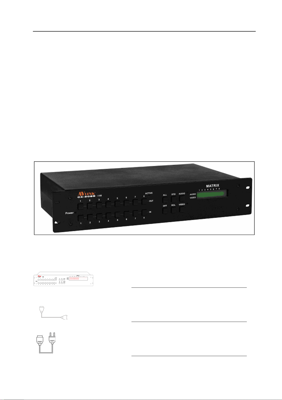
Figure 1-1 CX 2088 Matrix
1.0.2 CX Matrix System Packing
CX Matrix Host
RS-232 Communication Connecting Cable
Power Cord
4
Page 6
CX Matrix Switching System—User Manual
CX Matrix Testing and Application Software Disc
User Manual
Green T erm inal(M)
CX-2044 2 Pcs
CX-2084 2 Pcs
CX-2088 2 Pcs
Quantity
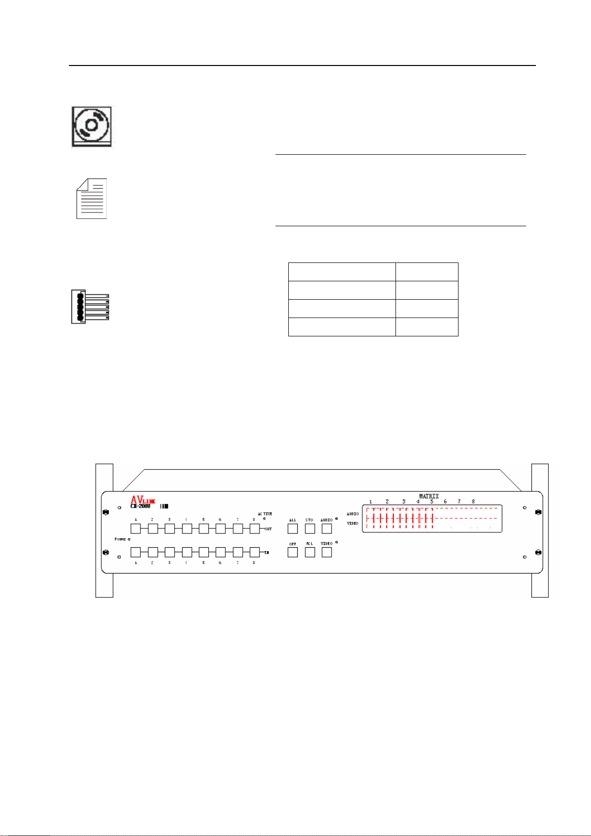
2.0 CX Matrix Host Installation
The CX Series Matrix Host has a black metallic housing. It can be placed on a sturdy desk or
installed on a 19-in rack. See Figure 2-1 below:
Figure 2-1 Installing the CX Matrix Host on a Standard Rack
5
Page 7
CX Matrix Switching System—User Manual
3.0 CX Matrix System Categories
The CX Series Matrix has following models to meet different requirements of different
users:
Technical
Parameters
Model
CX-2044 4 4 4 4 √ √
CX-2084 8 4 8 4 √ √
CX-2088 8 8 8 8 √ √
Video
Input Jack
Video
Output
Jack
Audio
Input Jack
Audio
Output
4.0 Matrix System Front and Rear Panels
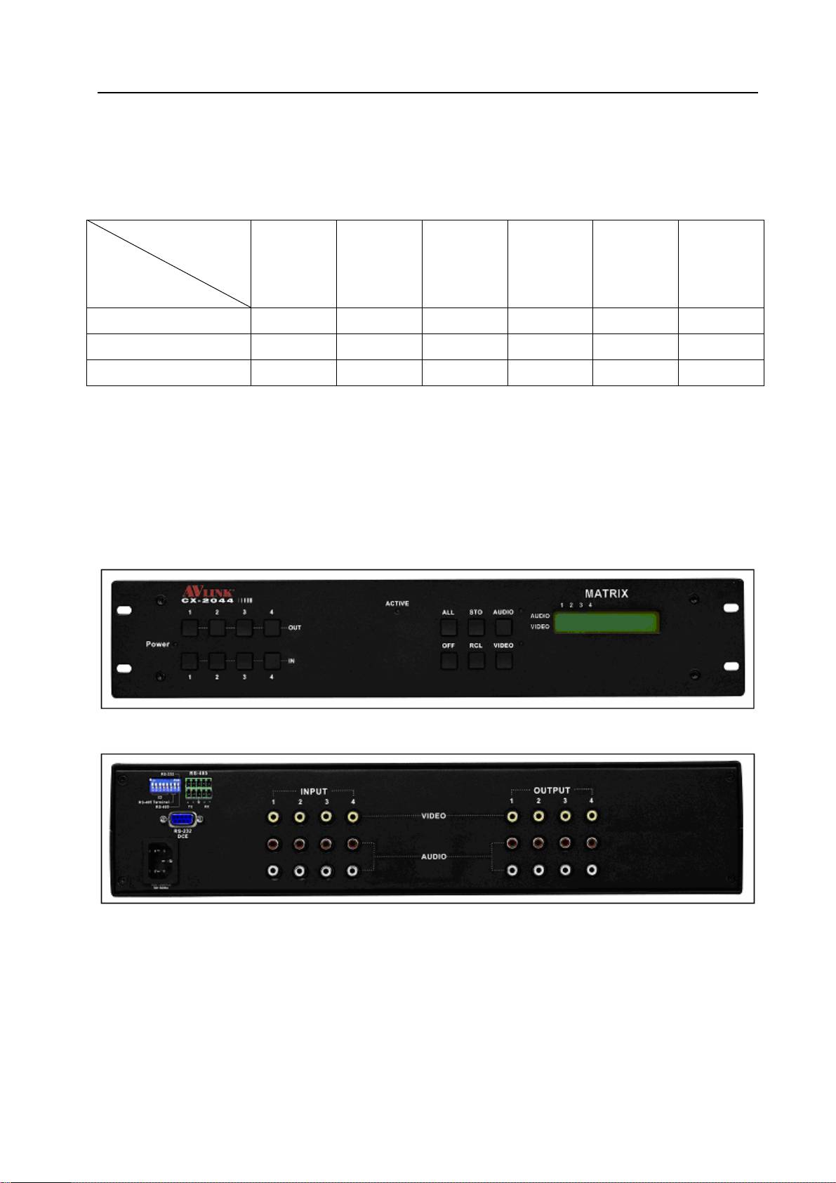
4.0.1 CX-2044 Front and Rear Panels
Jack
RS-485
Port
RS-232
Port
Figure 4-1 CX-2044 Front Panel
Figure 4-2 CX-2044 Rear Panel
6
Page 8
CX Matrix Switching System—User Manual
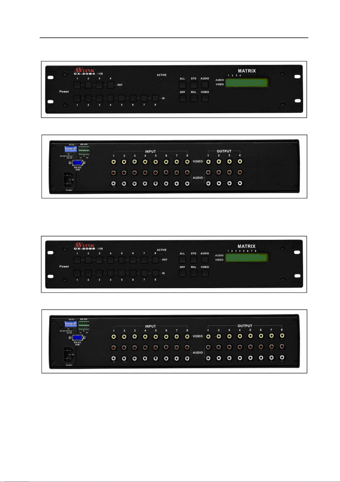
4.0.2 CX-2084 Front and Rear Panels
Figure 4-3 CX-2084 Front Panel
Figure 4-4 CX-2084 Rear Panel
4.0.3 CX-2088 Front and Rear Panels
Figure 4-5 CX-2088 Front Panel
Figure 4-6 CX-2088 Rear Panel
7
Page 9
CX Matrix Switching System—User Manual
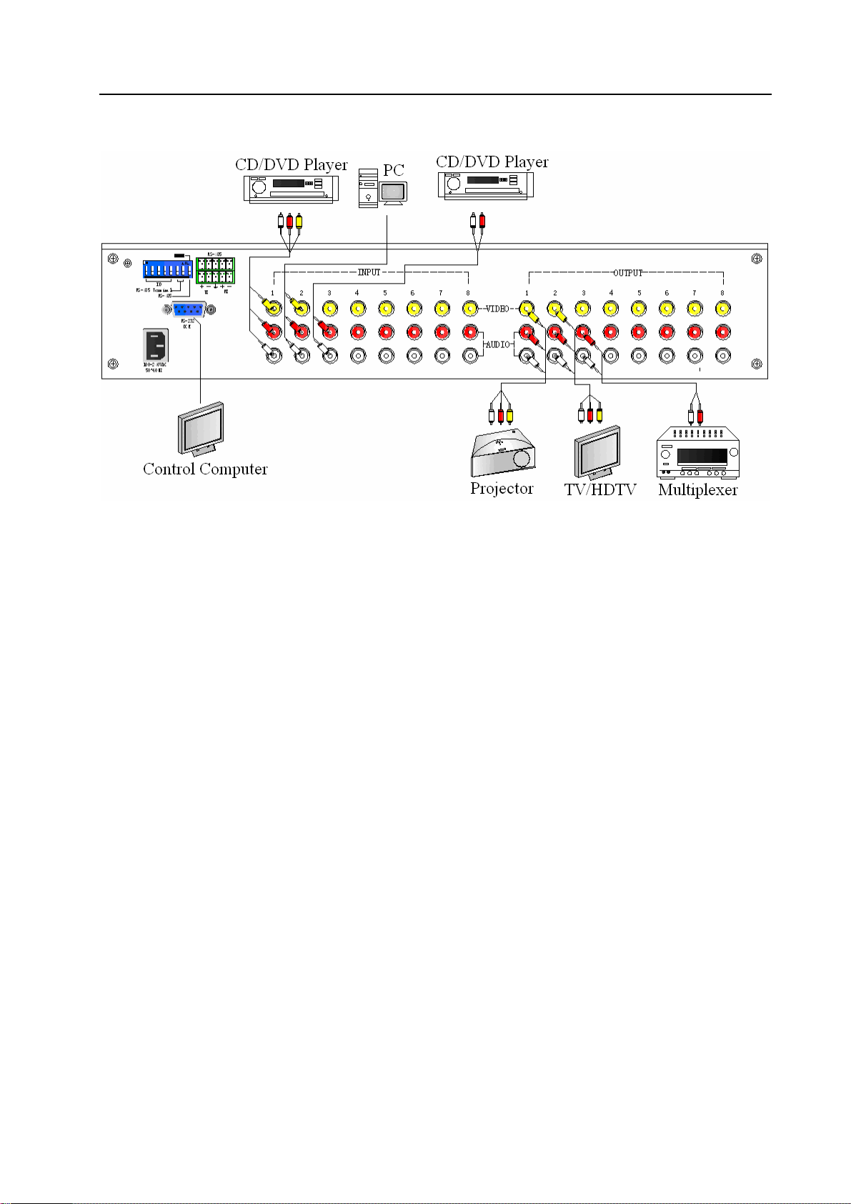
5.0 CX Matrix System and Peripherals Connection
Figure 5-1 CX Matrix System Connection
5.0.1 Input/Output Ports
Referring to the different models, the video signal input/output jacks are formed by the 4th
row and 8th row RCA female terminals. Lining from the top to the bottom are respectively video
and audio signal terminals. The video signal terminals are yellow in color while the audio signal
terminals are red (right audio channel) and white (left audio channel). Channels of the output
terminals are numbered from left to right from 1 to 8. Refer to the drawing on the housing for
port terminals of different models.
Different models of the CX matrix system provides a different number of input/output jacks
for users to connect to different audio/visual equipment including CD/DVD players, graphics
workstations, and number displays. The output terminals can be connected to projectors, video
recorders, displays and multiplexers and so on.
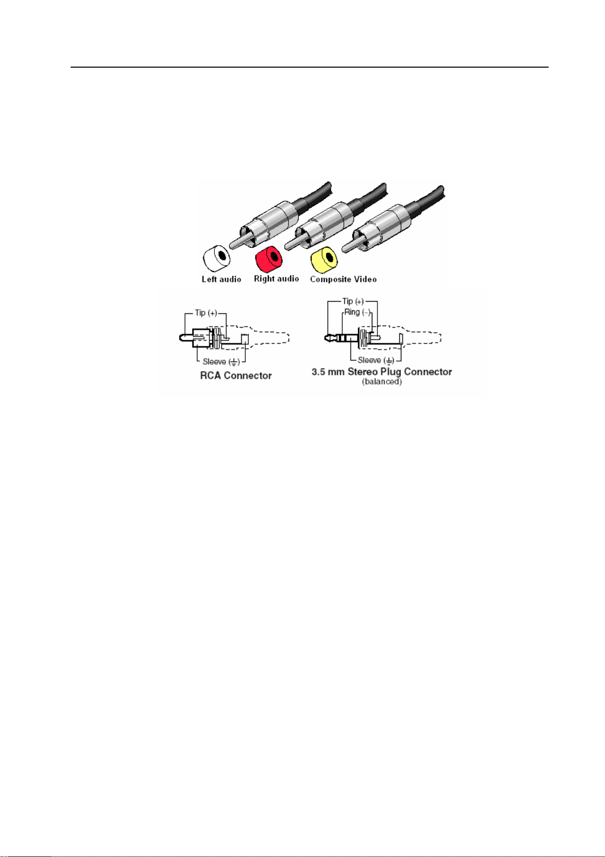
5.0.1.1 Audio/Video Connecting Cable
Different models of the CX matrix system provides a different number of input/output jacks
for users to connect to different audio/visual equipment including CD/DVD players, graphics
workstations, and number displays. The output terminals can be connected to projectors, video
recorders, displays and multiplexers and so on.
The RCA connecting terminal----audio/video port: The 4-hole RCA Jack is a conventional
audio connector. Its installation hole measures 14x18mm.
8
Page 10
CX Matrix Switching System—User Manual
The CX Matrix supports various AV signal sources.
AV Connector—standard AV Input RCA)Connector:
Type: Audio connectors are in pairs (left/right channels) (white/red) and video connector
(yellow)
CX matrix RCA jack connection, see Figure 6-2 below:
Figure 6-2 BNC Connection
Generally, the RCA audio terminals are indicated in pairs by different colors: the right audio
channel uses red color (or use the letter “R” to indicate “Right”); the left a udio channel is usually
black or white. Generally speaking, the RCA stereo cable is one cable to contain both left and
right audio channels.
Advantages: The AV connector realizes separate transmission of audio and video frequencies,
thereby averting decline of graphics quality due to audio/video interference. Presently, almost
every TV set provides this connector for video input.
Connection method: Use the 4-hole RCA Jack (commonly referred to as the sprayer head
which measures 14x18mm) for connection to input/output equipment. Connect the video, audio
RCA connectors of the signal source equipment output terminal to the same RCA connector of
the CX matrix input. Then, connect the RCA connectors of the CX matrix output, via a dedicated
RCA signal cable, to the RCA input jack of the output equipment.
NOTE: Correctly connect the two ends of the signal cable to the RCA connector, or else
discoloration happens or even no signal output.
Audio Connecting Cable:
The “Audio Input” and “Audio Output”jacks of the CX matrix can be used to connect a video
recorder and a multiplexer respectively.
The audio cable branches into left and right audio channels. The red RCA represents the right
audio channel and the white RCA represents the left audio channel.
9
Page 11

CX Matrix Switching System—User Manual
5.0.2 CX Matrix System and Computer Connection
Use the RS-232 connecting cable to connect the computer’s serial communication port
(COM1 or COM2) to the CX Matrix host’s RS-232 communication port and install the
application software. The computer can then exercise control over the CX matrix.
Figure 5-4 CX Matrix and Computer Connection
5.0.3 Remote Control and Settings
The CX matrix provides standard RS-232 and RS-485 serial communication ports. You can
use the front panel for key switching operation. You can also use the RS-232 or RS-485 serial
communication port to carry out remote operation. Additionally, it also supports RS-485 serial
control.
5.0.3.1 RS-232 Communication Port and Connection
The RS-232 port is a 9-pin female connector. The Leg functions are shown in the table
below:
Pin Leg Description
1 N/u Nil
2 Tx Send
3 Rx Receive
4 N/u Nil
5 Gnd Public Domain
6 N/u Nil
7 N/u Nil
8 N/u Nil
9 N/u NIl
10
Page 12

CX Matrix Switching System—User Manual
Figure 5-5
Figure 5-5(a)
11
Page 13

CX Matrix Switching System—User Manual
Figure 5-6
Note: The Matrix RS-232 port is defined by DCE.
5.0.3.2 RS-485 Communication Port
You can use the RS-485 port to control more than one CX product.
RS-485 Port as shown in Figure 5-7 below:
Figure 5-7
12
Page 14

CX Matrix Switching System—User Manual
5.0.3.3 On/Off Switch Switches
Figure 5-8
A. DIP SW-8:RS-232/RS-485 switches ON/OFF
ON:RS-232 Enables Single System or RS-485 Serial Master
OFF:RS-485 Enables RS-485 Serial Slave
B. DIP sw-6/7:RS-485 Terminator ON/OFF
ON:Terminator ON
OFF:Terminator OFF
C. DIP sw 1 to 5 Setting(address setting)
The ID number determines the position of a Matrix system. When multiple CX products are
connected to one PC or when the Matrix products are serially connected, the ID number decides
which CX product is to be controlled. Use the on/off switches 1, 2, 3, 4, 5 on the rear panel to set
the ID number as shown in Figure 5-2 below:
13
Page 15

CX Matrix Switching System—User Manual
On/Off Switching Positions ID Address
SW1 SW2 SW3 SW4 SW5
(Decimal)
Software ID
Address
On/Off
(Binary)
(Hexadecimal)
0 00 00000 OFF OFF OFF OFF OFF
1 01 00001 OFF OFF OFF OFF ON
2 02 00010 OFF OFF OFF ON OFF
3 03 00011 OFF OFF OFF ON ON
4 04 00100 OFF OFF ON OFF OFF
5 05 00101 OFF OFF ON OFF ON
6 06 00110 OFF OFF ON ON OFF
7 07 00111 OFF OFF ON ON ON
8 08 01000 OFF ON OFF OFF OFF
9 09 01001 OFF ON OFF OFF ON
10 0A 01010 OFF ON OFF ON OFF
11 0B 01011 OFF ON OFF ON ON
12 0C 01100 OFF ON ON OFF OFF
13 0D 01101 OFF ON ON OFF ON
14 0E 01110 OFF ON ON ON OFF
15 0F 01111 OFF ON ON ON ON
16 10 10000 ON OFF OFF OFF OFF
17 11 10001 ON OFF OFF OFF ON
18 12 10010 ON OFF OFF ON OFF
19 13 10011 ON OFF OFF ON ON
20 14 10100 ON OFF ON OFF OFF
21 15 10101 ON OFF ON OFF ON
22 16 10110 ON OFF ON ON OFF
23 17 10111 ON OFF ON ON ON
24 18 11000 ON ON OFF OFF OFF
25 19 11001 ON ON OFF OFF ON
26 1A 11010 ON ON OFF ON OFF
27 1B 11011 ON ON OFF ON ON
28 1C 11100 ON ON ON OFF OFF
29 1D 11101 ON ON ON OFF ON
30 1E 11110 ON ON ON ON OFF
31 1F 11111 ON ON ON ON ON
Figure 5-2 ID Number Setting Table
14
Page 16

CX Matrix Switching System—User Manual
5.0.3.4 CX Matrix System and Control System Connection
A. If your PC provides RS-232,please follow connection as shown in Figure 5-9 below:
Figure 5-9
NOTE: 1. RS-232 connection refer to previous Figure for operation;
2. RS-232 or RS-485 baud rates: 9600bps, no odd or even calibration address,8bit data
transmission address,1bit stop address(96,N,8,1);
3. Serial connection between Matrix RS-485 as follows:
TX(+) TX(+)
TX(-) TX(-)
RX(+) RX(+)
RX(-) RX(-)
4. Each DIP sw1-5 address must not set to same ID number.
15
Page 17

CX Matrix Switching System—User Manual
B. If your PC provides RS-485,please follow conection as shown in Figure 5-10 below:
Figure 5-10
NOTE: 1. RS-485 baud rate: 9600bps, no odd or even calibration address,8bit data transmission
address,1bit stop address(96,N,8,1);
2. Connect your PC RS-485 port to the Matrix RS-485 port as follows:
TX(+) TX(+)
TX(-) TX(-)
RX(+) RX(+)
RX(-) RX(-)
3. Serial connection between Matrix RS-485 ports as shown below:
TX(+) TX(+)
TX(-) TX(-)
RX(+) RX(+)
RX(-) RX(-)
4. Each DIP sw1-5 address must not set to same ID number.
16
Page 18

CX Matrix Switching System—User Manual
6.0 Matrix Control Panel Operation
6.0.1 Input/Output Switching Key Operating Mode
Fast audio/video switching of the Matrix systems can be done by pressing keys on the front
panel (refer to the “Front Panel Key Pressing Instructions” for detail key pressing.)
Operation methods as follows:
“Switching Method"+“Output Channel"+“Input Channel"
Follow instructions below:
“Switching Method"
For synchronous audio/video switching or alternative switching, select “Synchronous
Audo/Video Switching,” “Audio Switching” or “Video Switching” as per “Audio” and “Video”
keys.
“Output Channel"
The “OUT Row 1-8” keys on the front panel represent output channels 1 to 8 for connection to
peripheral display equipment.
“Input Channel"
The “IN Row 1-8” keys on the front panel represent input channels 1 to 8 for connection to the
currently connected channels of the signal source to be switched.
6.0.2 Front Panel Key Functions
Part Function Key Function
1
2 Output channel selection keys used for setting
3 Input channel selection keys used for setting audio/video
LCD display shows current CX matrix status and
operation hints.
audio/video output channels or for selection of Status
Mode or Reserved Number.
output channels or for selection of Status Mode or
Reserved Number.
4
ALL
Implement all output selection keys via certain input
route.
---Example: First press the “ALL” key, then select the
input channel to output to all output channels; first press
the “ALL”key, then press the “OFF”key to close all the
presently displayed swtitching status.
17
Page 19

CX Matrix Switching System—User Manual
Part Function Key Function
5
6
7
8
OFF
Close output channel key.
---First press to close the output channels, then press the
“OFF” key to close the specified channel.
STO
The “Reserve Key” saves all current input/output
corresponding relations.
---Example: Press the “STO”key, then press the output
channel key which you want to save to save all currently
displayed input/output corresponding relations.
RCL
The “Retrieve Key” retrieves the saved input/output
corresponding relations.
---Example: First press the “RCL” key, then press the
previously saved output channel key to retrieve the saved
input/output status and implement this status switching.
AUDIO
The “Audio Switching Selection Key” can unilaterally
switch from one channel to another output channel.
---Example: Press the “Audio” key to open or close the
audio switching function. When the LED (next to the
audio key) light goes on indicates the audio switching
function is open. When the LED light goes off indicates
the audio switching function is close.
9
VIDEO
The “Video Switching Selection Key” can unilaterally
switch from one channel to another output channel.
---Example: Press the “Video” key to open or close the
video switching function. When the LED (next to the
Video key) light goes on indicates the video switching
function is on. When the LED light goes off indicates the
video switching function is close.
18
Page 20

CX Matrix Switching System—User Manual
6.0.3 Operation Examples
Examle 1: Synchronously switch the NO. 1 audio/video signal to the NO. 3 and 4 output
channels.
Key LCD Display Operation
1. Press the NO. 3 key of the
output channel for 2
seconds, then enter the input
channel when the red 0 LED
indicators begin to flicker.
2. Press the NO. 1 key of the
input channel for 2 seconds
to select operation of
switching from NO. 1
channel to NO. 3 channel.
The LCD of NO. 3 channel
indicates channel NO. 1 for
both audio and video. Please
enter the output channel.
3. Press the NO. 4 key of the
output channel for 2
seconds, and enter the input
channel when the red 0 LED
indicators begin to flicker.
4. Press the NO. 1 key of the
input channel for 2 seconds
to select operation of
switching from NO. 1
channel to NO. 3 and NO. 4
channel. The LCD of NO. 3
and NO. 4 channels indicate
input channel NO. 1 for both
audio and video.
19
Page 21

CX Matrix Switching System—User Manual
Example 2: Synchronously switch the NO. 4 video signal to the NO. 1, 3, 5, 6 output channels.
Key LCD Display Operation
1. First press the “AUDIO”
key to turn off the Audio LED
light, then enter the output
channel.
2. Press the NO. 1 key of the
output channel for 2 seconds
and then enter the input
channel when the red 0 LCD
display begins to flicker.
3. Press the NO. 4 key of the
input channel for 2 seconds to
select operation of the
previously set switching from
NO. 4 channel to NO. 1
channel. Enter the output
channel when VIDEO shows
input channel as 4 on NO. 1
channel of the LCD.
4. Press the NO. 3 key of the
output channel for 2 seconds,
and enter the input channel
when the red 0 of the LCD
begins to flicker.
5. Press the NO. 4 key of the
input channel for 2 seconds to
select operation of the
previously set NO. 4 input
channel and NO. 1 and 3
output channels. When video
shows 4 on LCD NO.1 and
NO.3 channels, enter the
output channels.
6. Press the NO. 5 key in the
output channel for 2 seconds
and enter the input channel
when the red 0 indicator on the
LCD begins to flicker.
20
Page 22

CX Matrix Switching System—User Manual
Key LCD Display Operation
7. Press the NO. 4 key of the
input channel for 2 seconds to
select operation of previously
set NO. 4 channel to NO. 1, 3,
5 channels for output. Enter
the output channel when
VIDEO shows input channel
NO. 4 on NO. 1, 3 and 5
channels on the LCD.
8. Press the NO. 6 key of the
output channel for 2 seconds
and enter the input channel
when the red 0 LCD indicator
begins to flicker.
9. Press the NO. 4 key of the
input channel for 2 seconds to
select operation of the
previously set NO. 4 channel
to NO. 1, 3, 5, 6 channels.
VIDEO all shows input
channel 4 on channel NO. 1, 3,
5, 6 on LCD display.
7.0 Matrix Application Software
7.0.1 Software Introduction
The 《AV Matrix》 Matrix control software applies to different input/output matrixes.
7.0.1.1 Software Description
The《AV Matrix》 matrix testing software is an application developed for matrix testing and
application.
Tools: the software operation environment:
Window98/2000/NT/XP operatng systems
32M interal memory or above
10M hard disk space or above
CD-ROM
At least one serial communicatin port
21
Page 23

CX Matrix Switching System—User Manual
7.0.1.2 Software Activation
First, you must turn off power both to the CX matrix and to the computer. Then, connect the
matrix RS-232 port to the PC RS-232 port using the bundled communication cable. (Refer to the
previous section “CX Matrix and Control Computer Connection.”;
Turn on power to the CX matrix and the computer:
Activate the AV Matrix.exe on the bundled CD-ROM in the control computer to enter the
control software interface.
7.0.2 Software Features
The software controls signal connection between the corresponding input port and output port
as required. The main operation window is shown in Figure 7-1 below:
Figure 7-1 《AV Matrix》Control Software Usage Interface
Scroll on the left lower corner to view contents as shown below.
7.0.2.1 Main Operation Interface Features
Refer to the window menu above, the interface blue area shows crossing matrix of output
ports 01-08 and input ports of 01-08. On the lower right hand corner, you can select either
“Video”or “Audio”for signal switching or “Disconnect”to close all output ports. Click to check
the white boxes to the left of “Video” and “Audio” for specified signal transimission.
22
Page 24

CX Matrix Switching System—User Manual
Examples for Selecting Matrix Switching Functions:
Example 1: Now there is a CX-2088 matrix having all the input/output ports properly
connected to the equipment. Then needed input/output ports are set to Audio/Video channel 1
while Output is being switched to channels 2, 3, 5. There are two ways of operations if you want
to switch Audio/Video channel 3 to output channel 6 as follows:
First W ay: Make sure that the boxes to the left of “Video” and “Audio” have been selected.
Then, directly click the corresponding to turn it into ,thereby completing the
switching operation.
Second Way:
Step 1: Makre sure that you have checked the boxes to the left of “Video” and “Audio”.
Step 2: First select the “Output”number keys 02, 03 and 05 to the right, and select the “Input”
number key 01 to the bottom. Afterwards, press consecutively the previously selected “Output”
number keys 02, 03 and 05 (or you can press the “Deselect all output” key). This way, you have
selected “Input” 01 and “Output” 02, 03 and 05 switching.
Step 3: First select the “Output” number key 06 to the right, and select the “Input” number
key 03 to the bottom. Afterwards, press the previously selected “Output” number key 06 (or you
can press the “Deselect all output” key). This way, you have selected “Input” 03 and “Output” 06
switching.
Upon completion of the above 3 steps, you have actually completed the switching operation of
having Audio/Video channel 1 to Output channels 2, 3 and 5 while at the same time successfully
switched from Audio/Video channel 3 to Output channel 6.
Example 2: Now there is another CX-2088 matrix having all the input/output ports properly
connected to the equipment. You are required to set the Input/Output ports to Video channel 1
and switched to Output channels 1, 6 and 7 while Audio channel 2 is being switched to Output 8.
Follow the instructions below:
First W ay:
Step 1: Makre sure that you have selected “Video” and not “Audio”. In the matrix, directly
click the coordinate icons that fall between the Input number key 01 and the Output
number keys 01, 06, 07 and the selected icons will turn . This way, you have successfully
completed video switching operation of selecting Input 01 and Output 01, 06 and 07.
Step 2: Make sure that you have selected “Audio” and not “Video.” In the matrix, directly
click the coordinate icon that fall between the Input number key 02 and the Output
number key 08 and the selected icon will turn . This way, you have successfully
completed the audio switching operation of selecting Input 02 and Output 08.
23
Page 25

CX Matrix Switching System—User Manual
Upon completion of the above 2 steps, you have actually completed the switching operation of
having switched Video channel 1 to Output channels 1, 6 and 7 while at the same time
successfully switched from Audio channel 2 to Output channel 8.
Second Way:
Step 1: Make sure that you have selected “Video" and not“Audio";
Step 2: Select the output number keys 01, 06 and 07 to the right, and the input number key 01
to the bottom. Afterwards, press the previously-selected output number keys 01, 06 and 07
respectively (or press the “Deselect all output” key). This way, you have completed videio
switching of selecting input 01 and output 01, 06 and 07.
Step 3: Make sure that you have selected “Audio” and not “Video”;
Step 4: Select the output number key 08 to the right and the input number key 02 to the
bottom. Afterwards, press the previously-selected output number key 08 (or press the “Deselect
all output” key). This way, you have successfully completed audio switching of selecting input
02 and output 08.
Upon completion of the above 4 steps, you have actually completed the operation of switching
video channel 1 to output channels 1, 6 and 7 while switching audio channel 2 to output channel
8.
7.0.2.2 Disconnect Function Key
Close all the output ports.
A specific example of operation is described below:
The present input and output relations are shown in Figure 7-2 below:
Figure 7-2
24
Page 26

CX Matrix Switching System—User Manual
Now, you have to close output ports 03, 05 and 06.
Step 1: First press down the output number keys 03, 05 and 06 to the right;
Step 2: Press the “Disconnect” key;
Step 3: Press up the previously-pressed output number keys 03, 05 and 06 (or press the
“Deselect all output”key) to end the operation.
The final results will be as shown in Figure 7-3 below:
Figure 7-3
7.0.2.3 Select all output、DeSelect all output Switching Function Usage
(1)Select all output Function Description: You can use this function to select one port for input
and all output ports for output.
A specific example of operation is described below:
Example: Now, you have a CX-2088 matrix with all input and output ports properly
connected to the equipment. The needed input/output ports should be set to audio/video channel
1 while switching all output ports to output.
Make sure that you have selected boxes to the right of “Video” and “Audio”. Then, press
down the “Select all output” key. Afterwards, select the input 01 key to the bottom. Press all the
icons on row 01 to turn them into icons to end the operation.
(2)DeSelect all output Function Description: Use this function to close the “Select all
output”function.
25
Page 27

CX Matrix Switching System—User Manual
7.0.2.4 Disconnect all Commands
Function Description: To close all the switching methods.
Press the “Disconnect all” key to close linkage to all input and output ports.
7.0.2.5 Memory Function Usage
Function Description: To store and retrieve.
Store Functin Description: The Store Function saves all the present input/output switching
relations to any Locations from #1 to #8 you desired.
A specific example of the Store Function is described below:
Stores all the present input/output switching relations to Location #1. First, select Location
#1,as shown in the figure below:
,then click the save key to save all the present
input/output switching relations to Location #1.
Retrieve Function Description: To retrieve the saved input/output switching relations.
A specific example of the Retrieve Function is described below:
To retrieve the input/output corresponding relations saved in Location #1. First, select
Location #1 as shown in the figure below:
,then click the Load key to retrieve all the
input/output corresponding relations stored in Location #1.
7.0.2.6 Scan Function Usage
Use the mouse to click the Scan key to refresh the AV Matrix operating interface.
7.0.2.7 Options Function Applications
Function Activation:
In the main menu, select Options to prop up the Options window as shown in Figure 7-4(a)
26
Page 28

CX Matrix Switching System—User Manual
Figure 7-4(a) Figure 7-4(b)
Function Description:
Linking Methods: In “ ” select either COM1 port or COM2 port as shown in
Figure 7-4(b); in “ ” select 9600 for signal transmission as shown in Figure 7-4(a)
7.0.2.8 Exit Function Applications
Function Description: To exit the operating software.
7.0.2.9 Other Applications
Displays the presently saved switching status as shown in Figure 7-5 below:
Figure 7-5
When Video/Audio corresponding to Output is open, it shows the Output ports corresponds to
the Video/Audio Input ports; when they are close the word None will be shown in red in the
above table.
8.0 Communication Protocol and Control Command Code
Communication Protocol: Baud rate 9600bps, no odd or even calibration bit address, 8bit
transmission address, 1bit stop address.
Refer to the “Command list.pdf” on the CD-ROM for the command system.
27
Page 29

CX Matrix Switching System—User Manual
9.0 CX Matrix System Technical Parameters
Model
CX-2088 CX-2084 CX-2044
Technical
Parameters
Video Frequency
Enhancement 0dB
Bandwith
Max Transmission
150MHz (-3dB),Full Load
20nS(±1nS)
Delay
Switching Speed 50nS (Longest time)
Signal T ype Composite V ideo
Video Input
Port 8 RCA Female
Ports
8 RCA Female
Ports
Signal Strength Composite Video Frequency
Min./Max. Voltage Modulated Signal 0.5V~2.0Vp-p
Impedance
75Ω
4 RCA Female
Ports
Video Output
Ports 8 RCA Female
Ports
4 RCA Female
Ports
4 RCA Female
Ports
Min./Max. Voltage 2.5Vp-p
Impedance
75Ω
Audio Signal
Input/Output Ports RCA Female Ports
Signal Type Stereo, Balanced or Unbalanced Connection
Impedance
Input:〉10kΩ
Output: 75Ω
Max Input Level +19.5dBu
Max. Output Level +19.5dBu
Control T ype
Serial Control Port
RS-232,9Pin Female D-Type Port
Baud Rate & Protocol 9600bps, no odd or even calibration address, 8bit
transmission Address, 1bit Stop Address
Serial Control Port
Structure
Control Sequence
TX,RX,GND
《AV Matrix》
28
Page 30

CX Matrix Switching System—User Manual
Model
CX-2088 CX-2084 CX-2044
Technical
Parameters
Specifications
Power
Temperature
100VAC~240VAC,50/60Hz,Automatic Switch
Storage/Usage Temp.: -40℃~+85℃
Humidity Storage/Usage Humidity: 10%~90%
Housing
485(L)X275(W)X90mm(H)
Measurements
Product Wt. 3700g
Average Failure Time
30,000 Hours
Interval
Warranty 1 year free maintenance, lifetime maintenance
10.0 Common Problems and Solutions
1. What to do if the CX matrix front panel keys switching not responsive?
Answer: The CX matrix front panel keys employ scanning testing and require longer response
time. Press the keys for 2 seconds and then release. This way, key switching will be
responsive in operation.
2. What to do if matrix does not display or color display is abnormal after hot plug?
Answer: Switching of the matrix system goes through the IC chips. If the voltage difference
between the input signal equipment and the matrix equipment is too large, hot plug
could easily cause damage to the IC chips. Please turn off power to the system before
plugging or unplugging.
3. What to do if ghosting happens when Composite Video signals output to display?
Answer: Ghosting is often caused either by the projector, inferior cable quality or long
transmission distance. You are advised to adjust the projector or replace with better
quality cable.
4. What to do if discoloration happens or no video signal output?
Answer: Please check if both ends of the Composite Video signal connectors are correctly
connected.
5. What to do if the serial port (usually refer to the computer serial port) fails to control the CX
matrix?
Answer: Check that the communication port set by the control software is correctly connected to
the corresponding serial port of the equipment. Also, check if the computer
communication port is in good order.
6. What to do if the corresponding graphics fail to output during CX matrix switching?
Answer: (1) Check if there is signal on the input end. If there is no input signal, it could be that
29
Page 31

CX Matrix Switching System—User Manual
the cable is broken or the connector gets loosen. You are advised to replace the
connection cable.
(2) Check if there is signal on the output end. If there is no output signal, it could be that
the cable is broken or the connector gets loosen. You are advised to replace the
connection cable.
(3) Check if the output port number is the same as the controlled port number.
(4) If none of the above circumstances happen, it could be internal failure of the product
itself. You must send for repair by qualified technical engineers.
7. What to do if the power LED is not on, LCD has no display and no response in operation?
Answer: Check if the equipment power input is in good contact.
8. What to do if you sensed power leakage during plugging or unplugging of the audio/video
ports?
Answer: It could be that the equipment power is not properly earthed. You must properly earth
your equipment, otherwise product life can easily be shortened.
9. What to do if the LCD displays normally and the communication port has return code but no
graphics or audio output?
Answer: (1) It could be that the audio/video connectors got loosen. Simply replace the
connectors.
(2) It could be the connection cable short-circuited. Simply replace the cable.
(3) It could be the connection cable is broken. Simply replace the cable.
10. What to do if the CX matrix panel keys and communication ports are out of control?
Answer: Check if the equipment power input is in good contact and the communication ports are
in good order. If yes, it could be some internal failure of the product, please send for
repair by qualified technical engineer.
11. What to do if operation and function failure occurred?
Answer: Check if the equipment and the matrix system are in proper connection. If the problem
persists, send the product to the maintenance center for repair.
NOTE:
Do not replace the power cord yourself. If the power cord is damaged, ask your distributor to
send qualified technician to replace it for you.
© C&C TECHNIC TAIWAN CO., LTD. All rights reserved.
Trademarks:
All the companies, brand names, and product names referred to this manual are the trademarks
or registered trademarks belonging to their respective companies.
30
 Loading...