

Page 1
AUDIO
Distribution
Amplifier
(AS-914)
(AS-918)
USER MANUAL V1.0
AS-914/AS-918
Package Contents-
1 A VLINK AS-914 or AS-918 Audio Distribution
Amplifier
1 user manual
1 power adapter DC 12V 600mA
2 rack r ails, 6 screws
5 captive screw connectors for AS-914
9 captive screw connectors for AS-918
If anything is missing, please contact your vendor.
Introduction
Through the Audio Distribution Amplifier AS-914, AS-918,
by virtue of the audio of sound system from the DVD
player, can drive 4,8 speakers or sound system.
Features
Audio Frequency Response 20Hz~20KHz.
Input impedance >10kΩ.
1U 1/2 rack design.
Specifications
Function AS-914 AS-918
Audio In Connector
(Balanced St ereo)
Audio Out Connector
(Balanced St ereo)
Frequency Response 20Hz~20KHz
Power Adapt er (Min.) DC 12V 600mA
Housing Metal
Weight 665 g 700 g
Dimensions (LxWxH)
4 8
220x116x41 mm
FRONT VIEW
1. Power LED
REAR VIEW
1. Power Jack
2. Audio Input
3. Audio Output
*There are 4/8 out ports for AS-914 / AS-918.
-1-
1
Installation
1. Turn off the DVD player and speakers or sound system.
2. Connect the captive screw connectors male extension
cable between the DVD player and the “Audio Input”
ports of AS-914 / AS-918.
3. Connect the captive screw connectors male extension
cables between the speakers and the “Audio Output”
ports of AS-914 / AS-918.
4. Connect the power adapter and turn on the AS-914 /
AS-918.
5. Turn on the DVD player and speakers or sound system.
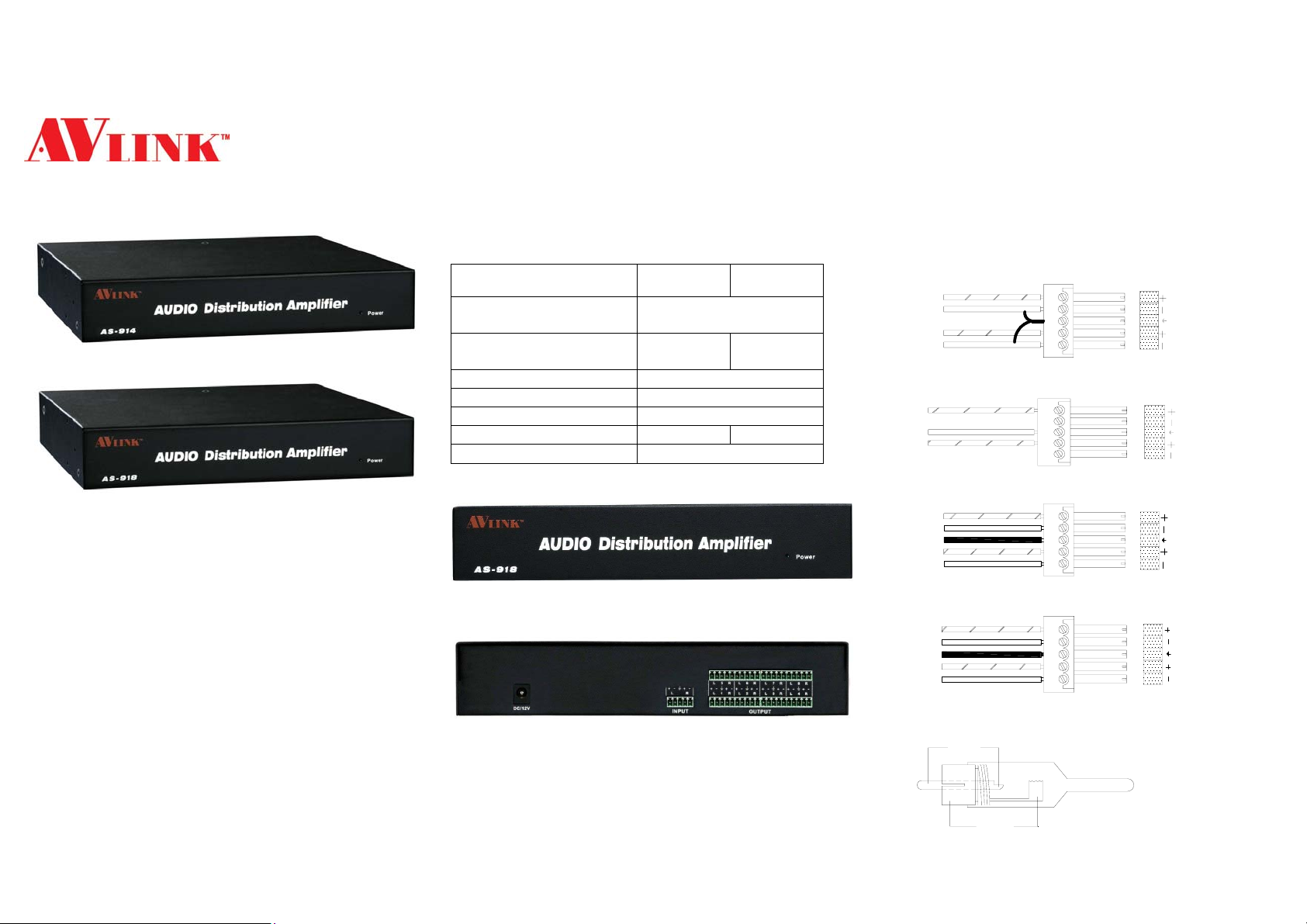
Installing Audio Connectors
TOP
GND
TOP
GND
Unbalanced Input
TOP
GND
TOP
See warn
See warn
Unbalanced Output
TOP
LOOP
GND
TOP
LOOP
R
Balanced Intput
TOP
LOOP
GND
TOP
LOOP
Balanced Output
TOP
GND
RCA CONNECTOR
-2-
R
AUDIO
L
R
(A)
L
R
L
L
AUDIO
(B)
AUDIO
(C)
AUDIO
(D)
(E)
Page 2

L
R
GND
(Unbalanced)
(F)
3.5 mm Stereo connector
1. The above connector, Unbalanced input/output is A, B.
Balanced input/output is C, D.
2. (WARNING)…Wiring errors or plugging the audio
connectors incorrectly will cause a loss for the audio
output circuits.
3. When making connections form the audio distribution
amplifier use existing audio cables and refer to figure E,
F.
4. Mono audio connector consist of the top and gnd.
Stereo audio connector consist of the top, loop and gnd.
The top, loop and gnd wires are also show above in the
audio connector diagrams.
© C&C TECHNIC TAIWAN CO., LTD. All rights reserved.
Trademarks:
All the companies, brand names, and product names
referred to this manual are the trademarks or registered
trademarks belonging to their respective companies.
-3-
 Loading...