

Page 1
MIPRO Electronics Co., Ltd.
2C E 46 5 A
Headquarters: 814 Pei-Kang Road, Chiayi, 60096, Taiwan.
Web: www.mipro.com.tw
E-mail: mipro@mipro.com.tw
ACT-80H Wideband Digital
Handheld Transmitter
User Guide
Design and specifications are subject to change without prior notice
AS121115
Page 2

IC:
This device complies with Industry Canada licence-exempt
RSS-123 ISSUE 2 standard. Operation is subject to the
following two conditions: (1) this device may not cause
interference, and (2) this device must accept any
interference, including interference that may cause
undesired operation of the device.
Wideband Digital Handheld Transmitter
Contents
1 Key Features
3 Bodypack Controls and Indicators
FCC Caution: To assure continued compliance, any
changes or modifications not expressly approved by the
party responsible for compliance could void the user's
authority to operate this equipment. (Example - use only
shielded interface cables when connecting to computer or
peripheral devices).
FCC ID label:
THIS DEVICE COMPLIES WITH PART 74 OF THE FCC
RULES. This equipment complies with FCC RF radiation
exposure limits set forth for an uncontrolled environment.
Disposal
2005 -08-1 3
Dispose of any unusable devices or batteries
responsibly and in accordance with any
applicable regulations.
Disposing of used batteries with domestic waste
is to be avoided!
Batteries / NiCad cells often contain heavy
metals such as cadmium(Cd), mercury(Hg) and
lead(Pb) that makes them unsuitable for
disposal with domestic waste. You may return
spent batteries/ accumulators free of charge to
recycling centres or anywhere else
batteries/accumulators are sold.
By doing so, you contribute to the conservation
of our environment!
5 Operating Instructions for Insertion &
Removing Battery
6 Patented Protection Cover
8 LCD
9
Display Screen
How to Setup Transmitter Parameters
20 Battery Status
23
25
Setting MUTE
General Tips for Improving System
Performance
012
Page 3

Wideband Digital Handheld Transmitter Wideband Digital Handheld Transmitter
Key Features
! Innovatively designed housing in MIPRO's
aesthetics and ergonomic style.
! Perfect combination of digital audio and wireless
transmission technology creates perfect sound
quality.
! Metal housing shows professional elegance look
and features solid grip and balanced weight.
! Patented design of the grille and battery housing
being integrated. It's easy to screw the grille to
open the battery compartment and install 2 AA
batteries.
! The unique flat top multi-layered steel grille for
condenser capsules and round top for dynamic
capsules protect the capsule against impact,
rolling and pop noise. The upper grille is able to
be detached easily for cleaning and hygiene
practices.
! The interior grille with fine metal mesh instead
of sponge foam minimizes pop noise and
effectively ensures sound clarity.
! Patented capsule suspension design virtually
eliminates the vibrations and handling noises.
! Premium detachable condenser or dynamic
microphone capsule module options
! True condenser capsule exhibits high fidelity,
wide dynamic range, fast transient responses,
low feedback howling, accurate sound image
characteristics, transparent sound quality, and
sustains maximum SPL.
! Backlit LCD displays working band-code, group,
channel, battery status, encryption status, RF
and audio levels.
! The bottom housing, where high-efficiency
antenna is integrated inside, embedded with
power switch, mute button and setup button for
programmed gain, limiter, low cut and RF output
power.
! The bottom housing is covered by patented end-
cap with color-coded channel identification clips.
Detach the end-cap to operate setup button.
Reverse the end-cap to shield power switch and
operate the mute button during operation.
! High efficiency and low spurious emissions
transmitting circuit is applied. An interferencefree working channel can be synchronized
automatically and quickly without any error by
MIPRO's patented ACT™ function.
Page 4
Wideband Digital Handheld Transmitter Wideband Digital Handheld Transmitter
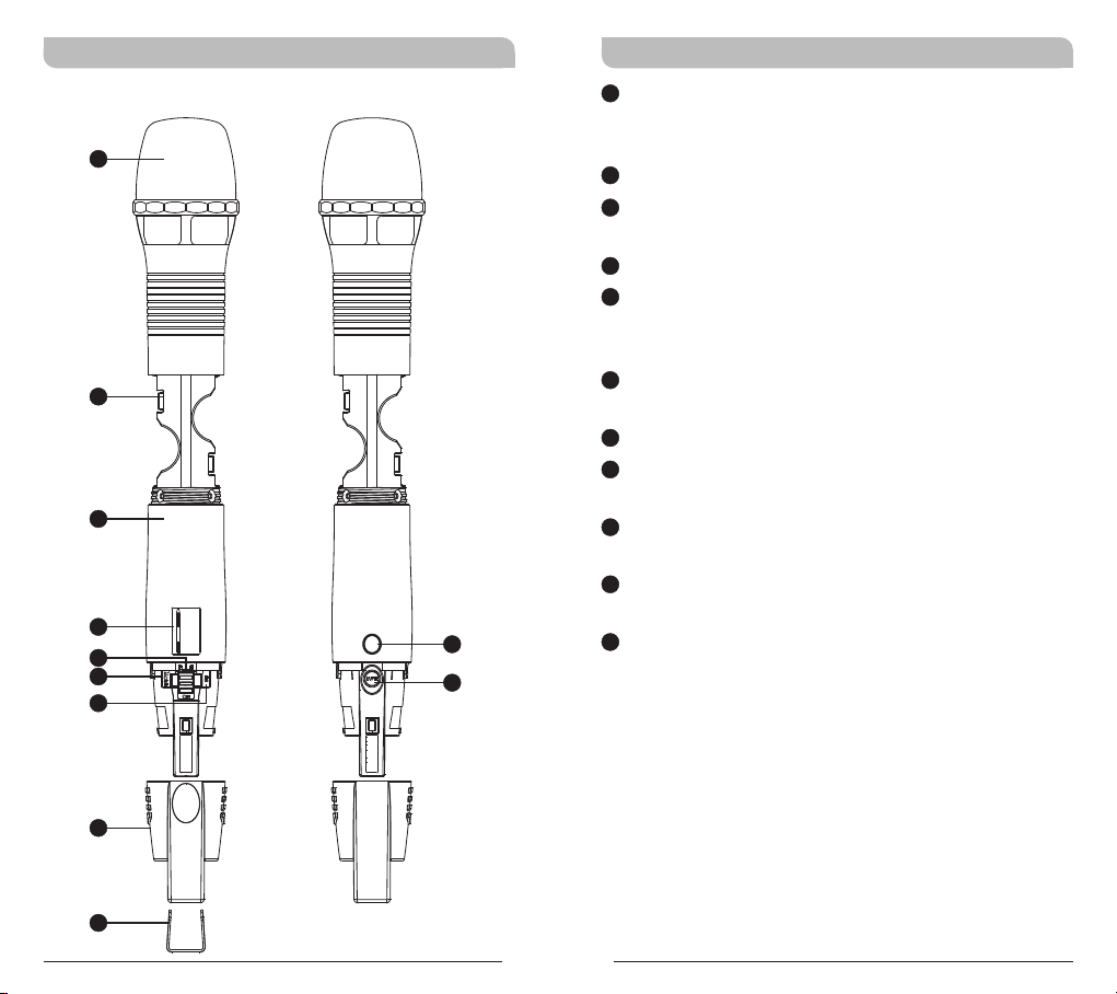
Bodypack Controls and Indicators
1
2
3
486.500MHz
4
5
6
7
FREQUE NCY
1
Capsule Module: Protects detachable
microphone capsule module and internal foam
prevents breathing, wind and POP noises.
2
Battery Compartment: Holds 2 'AA' batteries.
3
Housing: Protects transmitter PCB, battery
compartment and batteries.
4
LCD Panel: Displays transmitter parameters.
5
Power On/Off Switch: Slides the power switch
to the “ON” position for use or to the “OFF”
position when not in use.
6
MODE Button: Allows access to 8 available
functions displaying in LCD panel.
7
SET Button:
8
ACT Infrared (IR) Port: Receives signals from
Parameter selection button.
receiver to synchronize frequencies.
9
MUTE Button: To mute and un-mute the audio
signal temporary.
10
Protection Cover: Protects power switch and
prevents user has direct access to power switch.
11
8
9
Channel ID Clip: For channel identification
(Optional)
10
11
3
4
Page 5
Wideband Digital Handheld Transmitter Wideband Digital Handheld Transmitter
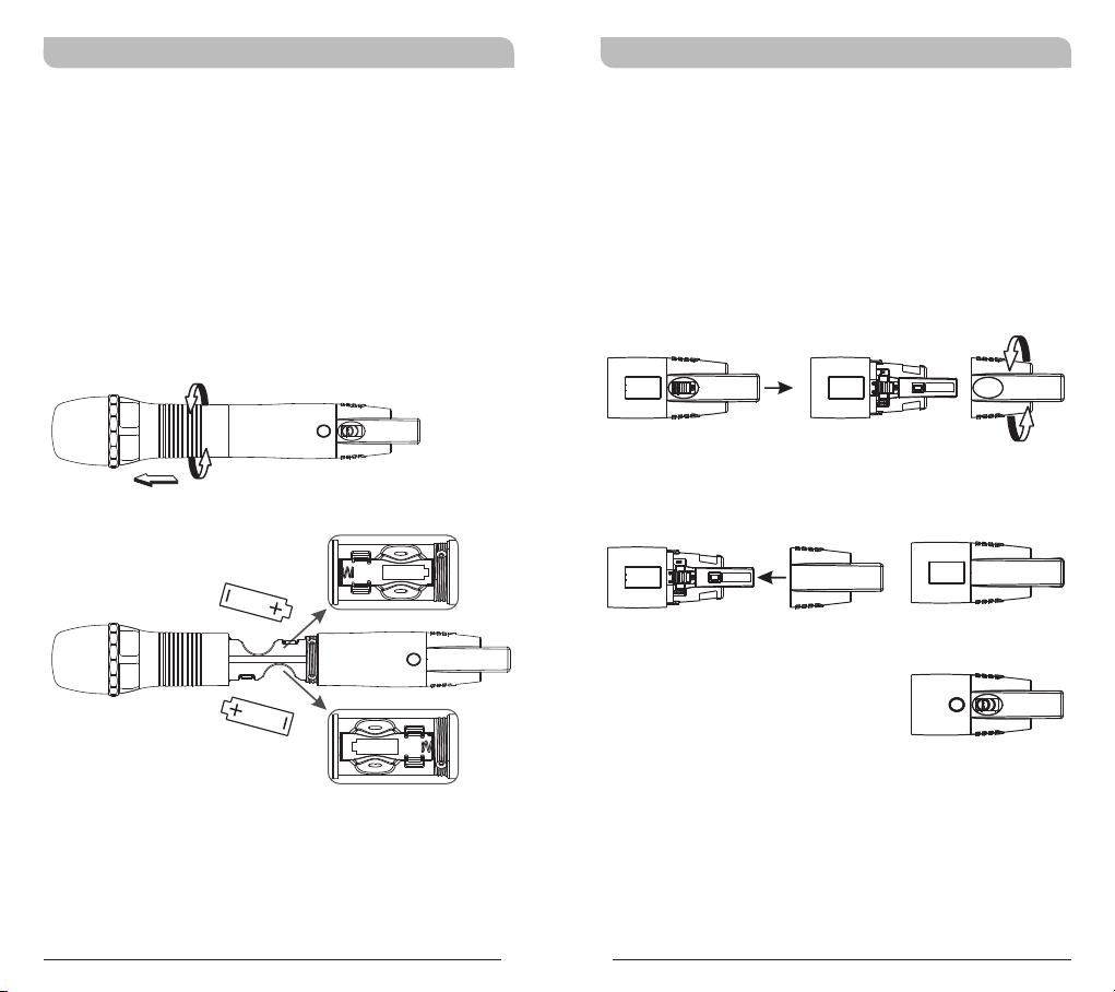
Operating Instructions for Insertion &
Removing Battery
!
Turn the microphone housing and pull it toward
capsule grille to expose battery compartment.
Insert two new AA alkaline batteries in the
!
battery compartment with correct polarity
orientation.
Turn power switch to ON position after battery
!
installation. If LCD does not lit, please check
battery polarity or change to fresh batteries.
Patented Protection Cover
Protection cover's patented design protects
accidental access to power switch and its rugged
material and snug fit offer protection to both power
switch and PCB during accidental drop.
Steps:
! Remove protection cover and turn it 180-degree.
! Install the protection cover after turning will
cover up power switch.
Mute function is open for easy acsess
Caution:
Remove the batteries if unused for a long period
of time to prevent battery leakage, corrosion and
causes damage to electronics.
! When power is off, reverse-installation of
protection cover will turn on the switch
automatically. To turn off the system, remove
the cover to turn off.
! Protection cover must be attached during
operation for full protection.
5
6
Page 6

Wideband Digital Handheld Transmitter Wideband Digital Handheld Transmitter
LCD Display Screen
! Channel identification clip can be attached to the
bottom of protection cover.
Fully Lit LCD Display
14
15
16
14
LCD Screen
15
Parameters Screen
16
AF (audio) MUTE
17
Transmitter Battery Meter
GRP CH
0 1 0 2
17
7
8
Page 7

Wideband Digital Handheld Transmitter Wideband Digital Handheld Transmitter
How to Setup Transmitter Parameters
! Remove protection cover to expose MODE
button and SET button.
! MODE Button:
Press “MODE” button to access one of the six
functions below.
! SET Button:
Press “SET” button and LCD wills start flashing.
During flashing, press SET button to change
parameters.
SET
FREQ UENCY
486.500MHz
MODE
A
GRP CH
0 1 0 2
F
ENC RYPTIO N
N O
G
RF P OWER
RF- L OW
A
Group and Channel
B
Frequency
C
Sensitivity Level
D
AF Low Cut
E
AF Limit
F
Encryption
G
RF Output Power
H
MUTE Mode
B
FRE QUENC Y
486.500MHz
E
AF L IMIT
Y E S
H
MUT E MODE
MAN U AL
C
AF G AIN
0 dB
D
AF L OW-CU T
LOW CUT
9
10
Page 8

Wideband Digital Handheld Transmitter Wideband Digital Handheld Transmitter
GRP CH: Displays Group and Channel Information
a. Press MODE and stop on the GRP CH function;
the display showing the current group and
channel will be flashing. After 5 seconds, the
display will stop flashing and the current group
and channel selection will be set.
b. The group and channel information is now
shown on the display. Changing the current
group and channel must be done on the
receiver.
GRP CH
0 1 0 2
**NOTE:
When programming a special frequency via
monitoring software, the LCD screen cannot
display the number. This is because this special
channel is not in the preset group and channel.
RF, the LCD panel will look like the illustration
below.
FREQUENCY: Displays Transmitter Frequency
Information
a. Press MODE and stop on the FREQUENCY
function; the display showing the current
frequency will be flashing. After 5 seconds, the
display will stop flashing.
b. The frequency information is now shown on the
display. Changing the current frequency must be
done on the receiver.
**NOTE:
To modify the transmitter's group, channel and
frequency, all three must be set at the receiver
and the new setting transmitted to the
transmitter via the ACT function.
FR EQU ENC Y
485.000MHz
GRP CH
11
12
Page 9

Wideband Digital Handheld Transmitter Wideband Digital Handheld Transmitter
AF GAIN: Setup and Change of Input Sensitivity
a. Press MODE and stop on the AF GAIN function;
the display showing the current status will be
flashing and is ready to be modified.
b. Every push of the SET button increases the dB
value by 3dB to a maximum of 6dB.
**NOTE:
1. The higher the gains are set, the lower the
dynamic range for signal input and the
greater the danger of unwanted noises and
feedback getting into the system.
2. When using electronic guitar, gain should set
at 0dB.
3. Please make sure input signal strength does
not exceed 2 Vrms (gain=6dB) as it is the
maximum input strength allowed for
transmitter without causing distortion.
AF G AIN
0 dB
AF G AIN
3 dB
AF G AIN
6 dB
AF LOW-CUT: Setup and Change of Low Frequency
Cut Off
a. Press MODE and stop on the AF LOW-CUT
function; the display showing the current status
will be flashing and is ready to be modified.
b. Press the SET button while the display is
flashing to change to LOW CUT or FLAT as
desired.
**NOTE:
When the AF LOW-CUT function is LOW CUT,
the frequency response below 100Hz will
decrease about 3dB with a slope of
-6dB/Octave.
AF LOW -CU T
LOW CUT
AF LOW -CU T
FLAT
13
14
Page 10

Wideband Digital Handheld Transmitter Wideband Digital Handheld Transmitter
AF LIMIT: Setup and Change of Input Limit
a. Press MODE and stop on the AF LIMIT
function; the display showing the current status
will be flashing and is ready to be modified.
b. Press SET while the display is flashing to change
the setting to ON or OFF.
**NOTE:
When the LIMIT is ON, the maximum output of
the receiver is limited to 1V.
AF LIM IT AF LIM IT
Y E S N O
ENCRYPTION: Displays Information of Encryption
a. Press MODE and stop on the ENCRYPTION
function; the display showing the current status
will be flashing.
**NOTE:
1. The ENCRYPTION function displays status
information only. Changing of the current
status must be done from the receiver via
the ACT function.
2. The ENCRYPTION function must be set at
receiver first then using ACT to program the
transmitter.
EN CRYP TI ON
N O
15
16
Page 11

Wideband Digital Handheld Transmitter Wideband Digital Handheld Transmitter
RF POWER: RF Power Selection
a. Press MODE button for selection of RF POWER.
Selection of RF-HI or RF-LOW can be selected
once the RF POWER LCD starts blinking.
b. Press SET button to select and set RF-HI or
RF-LOW.
**NOTE:
RF-HI has 50mW transmitting power. RF-LOW
has 10mW transmitting power. Set appropriate
power to meet region/country regulations.
RF POW ER
RF-H I
RF POW ER
RF-L O W
MUTE MODE: Mute model selection
a. Press MODE button for selection of MUTE
MODE. Selection of MANUAL or AUTO or
DISABLE can be selected once the MUTE
MODE LCD starts blinking.
b. Press SET button to select and set MANUAL or
AUTO or DISABLE.
c. LCD will stop blinking and change will not be
saved if setting is not done within 5 seconds.
d. MANUAL: Mute function is controlled by the
Mute button at “MANUAL” mode.
! Press Mute button to enter mute status. At
mute status, AF indicators will become “AF
MUTE” and blink continuously. Press Mute
button again to release mute status.
! AF MUTE status will be released automatically
when turning off.
e. AUTO: Mute button can not be activated at
the AUTO mode. Mute function will be activated
by the microphone itself automatically.
! Microphone will enter mute status when
positioning the capsule downward and the
mute status will be released automatically
when positioning the capsule upward.
! Idle the microphone for 4 seconds to enter
mute status automatically. Touch or use the
microphone again to release the mute status.
f. DISABLE: MUTE button is not operable.
17
18
Page 12

Wideband Digital Handheld Transmitter Wideband Digital Handheld Transmitter
Battery Status
MUT E MODEMUT E MODEMUT E MODE
DISABLEAUTOMANUAL
Indicates the power remaining in the transmitter
battery. When the battery has less than 10% power
remaining it must be replaced. If an under voltage
condition continues, the LCD will show “OFF...” and
the system will shut down to prevent being overly
discharged.
MU TE M ODE
MANU A L
MUTE
MU TE M ODE
MUTE
AF MUT E
AF MUTE
blinks continuously
10 0% 80 % 60 % 40 % 20 % 10 %
19
20
Page 13

Wideband Digital Handheld Transmitter Wideband Digital Handheld Transmitter
Power Button
! Turn the power switch to ON position where
transmitter will be activated and LCD will lit up.
! Turn the power switch to OFF position to shut
down the transmitter.
! When the power switch is turned off, the LCD
will show “OFF...” (for Power Off) first and then
the system will shut down and no further
messages will be displayed.
OFF...
ERR: Error Code
If the LCD displays “ERR” after turning on the
power, it indicates the operation is not correct. The
error codes are as follows:
ROM-ER →Transmitter does not have the initial
data so the microphone is completely
dead and cannot be programmed.
ERROR1 →Failure on RF circuitry, frequency
cannot be programmed.
NO----OR3 →Frequency to be programmed into the
transmitter exceeds the highest
frequency of the designated
frequency band of the transmitter.
NO----OR4 →Frequency to be programmed into the
transmitter exceeds the lowest
frequency of the designated
frequency band of the transmitter.
**NOTE:
NO----OR3 and NO----OR4 will not change the
transmitter's original frequency and the
transmitter will still operate normally with the
error message on display. To remove the error
message from the display panel, please switch
off the transmitter and switch it on again.
21
22
Page 14

Wideband Digital Handheld Transmitter Wideband Digital Handheld Transmitter
Setting MUTE
! Press MUTE button to enter mute status. At
mute status, AF indicators will become “AF
MUTE” and blink continuously. All the functions
can be operated and ACT can be activated at
the mute status. All the operations of functions
are the same with the ones at regular status.
! Press MUTE button again to release mute status
; AF MUTE status will be released automatically
when turning off.
! MUTE button can not be activated at “AUTO”
and “DISABLE” mode.
MUTE button
MUTE
A
GRP CH
0 1 0 2
AF M UTE
F
ENC RYPTIO N
N O
AF M UTE
G
RF P OWER
RF- L OW
AF M UTE
B
FRE QUENC Y
486.500MHz
AF M UTE
E
AF L IMIT
Y E S
AF M UTE
H
MUT E MODE
MAN U AL
AF M UTE
C
AF G AIN
0 dB
AF M UTE
D
AF L OW-CU T
LOW CUT
AF M UTE
GRP CH
M U T E
AF MUT E
FR EQU ENC Y
486.500MHz
AF MUT E
23
24
Page 15

Wideband Digital Handheld Transmitter Wideband Digital Handheld Transmitter
General Tips for Improving System
Performance
1. Performer should avoid holding the microphone over
or near the antenna section as this will deteriorate
transmission efficiency. Severe deterioration if
performer directly covers up the antenna section with
both hands.
2. Many performers tend to hold the microphone by the
top grille. Unfortunately, this position seriously
degrades both the sound quality and directionality of
a microphone. Even the most expensive microphones
will have its original sound quality compromised by
this method. Grabbing a microphone by the grille will
isolate the capsule's acoustic resonance circuit and or
change the capsule resonator's frequency. This
results in an inferior performance in both frequency
response and the separation of directionality. In
addition, a palm's sound-focusing effect will tend to
strengthen resonances in certain frequencies and can
cause unwanted echo.
3. A proper technique is required for using directional
microphones because the distance between the
microphone and your mouth has a significant impact
on sensitivity and performance. There is an inverse
relationship between microphone sensitivity and the
distance from the mouth to the microphone.
Consequently, performers with a ''weaker'' sound
level cannot expect to hold the microphone too far
away from their mouth and compensate by turning
up the amplifier volume to increase the sound level
as this can easily cause echo or feedback. In
contrast, performers with a ''louder'' sound level
should not hold the microphone too close as this can
easily result in distortion by causing the amplifier
system to be overloaded.
25
4. Furthermore, a large-diaphragm directional
microphone has a very distinct proximity effect.
When the microphone is close to the mouth, the
bass response is strengthened as the distance gets
closer. Therefore, if a performer's sound is
insufficient in bass, they can hold the microphone
closer and use the proximity effect to help
compensate for the lower bass level. Conversely, if a
performer's voice is too heavy in the bass register,
increasing the distance between the microphone and
their mouth will decrease the proximity effect and
reduce the bass response, thus making their voice
become clearer and brighter.
5. It is recommended to keep the grille and sponge
windscreen clean to avoid any substance blocking the
proximity effect of the microphone.
26
 Loading...