

Page 1
MIPRO Electronics Co., Ltd.
2CE40 1 B
Headquarters: 814 Pei-Kang Road, Chiayi, 60096, Taiwan.
Web: www.mipro.com.tw
E-mail: mipro@mipro.com.tw
Handheld Transmitter Microphone
User Guide
Design and specifications are subject to change without prior notice
AS110930
ACT-30Hr ACT-30H
Page 2

Handheld Transmitter Handheld Transmitter
Contents
1 Profile
2 Key Features
3 Handheld Controls and Indicators
perating Instructions for Insertion &
5 O
Removing Battery
6 Operating Instructions
7 LCD Screen
8 Battery Status
9 General Tips for Improving System
Performance
Profile
There are two types of antenna design for the
handheld transmitter microphones “built-in” and
“external”. The “built-in” design is normally
incorporate upper side of PCB in the housing and
the microphone capsule module as transmitting
antenna. The advantages are to avoid the antenna
breakage due to external design, inconvenience and
able to shorten the microphone housing design.
However, its drawbacks are poor transmission
efficiency especially when replacing microphone
capsules, unstable and deteriorated transmission
efficiency if it is gripped over the antenna area. The
“external” design enhances transmission efficiency
and stability, however, it causes inconvenience and
it may be damaged by accidental crashing.
MIPRO's patented design provides an ideal solution.
The antenna is integrated in the battery holder at
the bottom side of the housing, so it successfully
combines the advantages of both “built-in” and
“external” design.
The matched antenna and transmitter circuit
enhance transmission efficiency and stability
regardless capsules and battery replacement, or
change of grip positions and housing materials.
0 1
Microphone capsule, audio modulation, RF output
and antenna transmission constitute the perfect
straight-line layout of the transmitter PCB so that it
can achieve the best transmission quality and
efficiency. ACT-30H/ACT-30Hr are the most evolved
design model for built-in antenna transmitters
nowadays.
Page 3
Handheld Transmitter Handheld Transmitter
Key Features
! The microphone capsule is connected to the transmitter
PCB and then screwed onto the housing to prevent the
potential malfunction caused by improper contact.
! Modularized PCB and microphone capsule can be easily
detached and assembled. Optional premium microphone
capsule modules are available.
! ACT-30H is constructed of sturdy plastic housing to
enhance the transmission efficiency. Special coated
treatment prevents from handling noise and paint
stripping.
! ACT-30Hr is equipped with remote-control volume buttons.
! Proprietary lockable on/off switch to avoid accidental
power off.
! Durable construction of integrated housing and battery
compartment, allowing 2 AA type batteries easily to be
inserted and replaced.
! Battery housing design secures the battery installation to
prevent the malfunction when knocked. Multi-color rings
for easy channel identification.
! LCD on the housing displays working group, channel,
battery level and error codes.
! High-efficiency low spurious emissions UHF PLL
synthesized RF technology.
! An interference-free working channel can be synchronized
quickly and precisely by MIPRO's proprietary ACT function.
! MIPRO vocal condenser microphone capsule exhibits high
fidelity, wide dynamic range, fast transient responses, low
feedback howling, accurate sound image characteristics,
transparent sound quality and extremely low handling
noise.
! Proprietary high dynamic range modulation circuitry
sustains a maximum SPL of 140dB so performers can be
confident it won't distort when sing loudly.
! Optional MU-89b true condenser microphone capsule is
ideal for natural sound reproduction.
! Built-in volume buttons in ACT-30Hr handheld transmitter
enable volume loudness can be adjusted wirelessly for
MIPRO MA-708 & MA-808 portable PA systems.
2 3
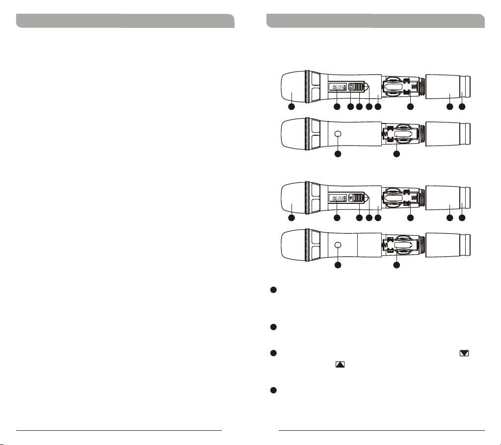
Handheld Controls and Indicators
ACT-30Hr
BAT
GROUP
CHANNEL
2 3 4 5 6 7 8 91
10 11
ACT-30H
BAT
GROUP
CHANNEL
2 4 5 6 7 8 91
10 11
1
Top Grille: Protects detachable microphone
capsule module and internal foam prevents
breathing, wind and POP noises.
2
LCD Screen: Displays group, channel, battery
status and error codes.
3
Remote Volume Control Buttons: Press to
decrease or to increase volume loudness
wirelessly.
4
Power On/Off Switch: Slide the power switch
to the “ON” position for use or to the “OFF”
position when not in use.
(Figure 1)
Page 4

Handheld Transmitter Handheld Transmitter
5
Lockable On/Off Switch: Slide the switch to
the “ON” position after power-on to avoid
accidental power off during performance. Slide
the switch to “OFF” position before power-off
and conserve battery power.
6
Housing: Upper portion connects to the
microphone capsule module. Internally it holds
the transmitter PCB and battery compartment.
7
11
Battery Compartment: Accommodates 2 AA
alkaline.
8
Battery Compartment Cover: Protects
battery compartment and holds batteries.
9
Color-Coded Ring: Available in different colors
for channel differentiation.
10
ACT Infrared (IR) Port: Receives signals from
receiver to synchronize frequencies.
Operating Instructions for Insertion &
Removing Battery
BAT
GROUP
CHANNEL
8
(Figure 2)
1. Gently twist the microphone housing in a
counter-clockwise direction
2. Remove the old batteries from the battery
compartment, if any are installed.
3. Insert two new AA alkaline batteries in the
battery compartment with correct polarity
orientation.
4 5
Page 5

Handheld Transmitter Handheld Transmitter
Operating Instructions
1. LCD screen on the transmitter and the RF
level/indicator shown on the receiver will be lit
when the microphone is turned-on, denoting
normal status. A blank LCD screen maybe due to
an incorrect battery polarity orientation.
2. The audio level or indicator show on the receiver
will be lit when there is audio line or microphone
input from the transmitter.
Caution
Remove the batteries if unused for a long period of
time to prevent battery leakage, corrosion and
causes damage to electronics.
LCD Screen
GR OUP
CH ANN EL
ER R
! ERR Message: When “ERR” appears in the
display it indicates that an operational error has
occurred. Please refer to the following codes to
diagnose which error you are experiencing.
ERR no01 EEPROM is not being programmed or
ERR no02 For testing only.
ERR no03 The frequency you want to program is
ERR no04 The frequency you want to program is
internal data error.
above the switching bandwidth of the
transmitter. Use a receiver with an
appropriate frequency group. (At this time
the microphone is still operating and the
frequency remains unchanged. To clear the
displayed "ERR" message, switch the
handheld transmitter off and on again.)
below the switching bandwidth of the
transmitter. Use a receiver with an
appropriate frequency group. (At this time
the microphone is still operating and the
frequency remains unchanged. To clear the
displayed “ERR” message, switch the
handheld transmitter off and on again.)
BAT
6 7
! “Group” & “Channel” : When both the group
and channel numbers are displayed, it means that
you are using the pre-programmed frequency of
the receiver.
! “Channel” Only : If “Channel” only is displayed,
it means that you are using a frequency which is
not pre-programmed.
Page 6

Handheld Transmitter Handheld Transmitter
Battery Status
10 0% 80% 40 % 10% 0%
Indicates the power remaining in the transmitter
battery. When the battery has less than 10% power
remaining it must be replaced or recharged. If an
under voltage condition continues, the LCD will show
“Poff” and the system will shut down to prevent
being overly discharged.
“Poff” - Power Off :
When the power switch is turned off, the LCD will
show “Poff” (for Power Off) first and then the
system will shut down and no further messages will
be displayed.
General Tips for Improving System
Performance
1. Performer should avoid holding the microphone over or
near the antenna section as this will deteriorate
transmission efficiency. Severe deterioration if performer
directly covers up the antenna section with both hands.
2. Many performers tend to hold the microphone by the
top grille. Unfortunately, this position seriously degrades
both the sound quality and directionality of a
microphone. Even the most expensive microphones will
have its original sound quality compromised by this
method. Grabbing a microphone by the grille will isolate
the capsule's acoustic resonance circuit and or change
the capsule resonator's frequency. This results in an
inferior performance in both frequency response and the
separation of directionality. In addition, a palm's soundfocusing effect will tend to strengthen resonances in
certain frequencies and can cause unwanted echo.
3. A proper technique is required for using directional
microphones because the distance between the
microphone and your mouth has a significant impact on
sensitivity and performance. There is an inverse
relationship between microphone sensitivity and the
distance from the mouth to the microphone.
Consequently, performers with a ''weaker'' sound level
cannot expect to hold the microphone too far away from
their mouth and compensate by turning up the amplifier
volume to increase the sound level as this can easily
cause echo or feedback. In contrast, performers with a
''louder'' sound level should not hold the microphone too
close as this can easily result in distortion by causing
the amplifier system to be overloaded.
8 9
Page 7

Handheld Transmitter Handheld Transmitter
4. Furthermore, a large-diaphragm directional microphone
has a very distinct proximity effect. When the
microphone is close to the mouth, the bass response is
strengthened as the distance gets closer. RF, if a
performer's sound is insufficient in bass, they can hold
the microphone closer and use the proximity effect to
help compensate for the lower bass level. Conversely, if
a performer's voice is too heavy in the bass register,
increasing the distance between the microphone and
their mouth will decrease the proximity effect and
reduce the bass response, thus making their voice
become clearer and brighter.
5. It is recommended to keep the grille and sponge
windscreen clean to avoid any substance blocking the
proximity effect of the microphone.
& IC - ID
THIS DEVICE COMPLIES WITH PART 74 OF THE FCC RULES
AND RSS-123 ISSUE2 OF CANADA. OPERATION IS
SUBJECT TO THE FOLLOWING TWO CONDITIONS:
(1) This device may not cause interference.
(2) This device must accept any interference, including
interference that may cause undesired operation of the
device. This equipment complies with FCC RF radiation
exposure limits set forth for an uncontrolled environment.
Disposal
2005 -08-1 32005 -08-1 3
Dispose of any unusable devices or batteries
responsibly and in accordance with any
applicable regulations.
Disposing of used batteries with domestic
waste is to be avoided!
Batteries/NiCad cells often contain heavy
metals such as cadmium(Cd), mercury(Hg)
and lead(Pb) that makes them unsuitable for
disposal with domestic waste. You may return
spent batteries/accumulators free of charge to
recycling centers or anywhere else
batteries/accumulators are sold.
By doing so, you contribute to the
conservation of our environment!
10 1 1
 Loading...