


USER MANUAL
AVL DITEST DPM 800
ID number:
AT7639E
Revision:
02
Issued:
03 / 2018
Data subject to alteration. All
data valid at time of printing.
FUTURE SOLUTIONS FOR TODAY

AVL DiTEST GmbH
Alte Poststrasse 156
A-8020 Graz / AUSTRIA
Tel: +43 316 787 - 0
Fax: +43 316 787 - 1460
ditest@avl.com
www.avlditest.com
Copyright © 2016 AVL DiTEST GMBH, all rights reserved.
The contents of this publication, as a whole or in part, may not be reproduced in any form
or passed on to third parties without the prior written consent of AVL DiTEST. This
publication was written exercising reasonable care. AVL DiTEST can therefore not accept
any liability whatsoever for any errors or omissions as well as for any possible damage.

AVL DiTEST DPM 800
Warnings and safety information
User manual
I
Warnings and safety information
This equipment manual contains important warnings and safety information
which must be observed by the user.
The product is only intended for a very specific application described in the
equipment manual. Furthermore, the most important prerequisites and safety
measures required for the us e a nd oper ati on o f the pro duct are ex plai ned to e nsu re
smooth operation.
We do not accept any warranty and liability for applications other than the
application described and without observing the required preconditions and safety
measures.
The product may only be used and operated by personnel that due to its professio nal
qualification is able to observe the required safety measures when using and
operating the equipment. It may only be operated with the accessories and
consumables supplied by DITEST or approved by DITEST. Since with this product
the measuring resul ts not only depend on proper f unctioning of the product , but also
on a number of further conditions, it is necessary to have the results generated by
the product checked (e.g. plausibility check) by an expert prior to implementing
further measures based on the generated measured value.
Adjustments and maintenance of live, opened devices may only be carried out by
qualified personnel trained for that purpose and that is aware of the risks involved.
The product may only be repaired at the supplying factory or by the qualified
personnel trained for that pur pose.
When using the produc t, a sp ecialist must ens ure th at neither the tes t object nor th e
test facility can operate in such a manner that it might damage property or put
personnel at risk.

Warnings and safety information
AVL DiTEST DPM 800
II
User manual

AVL DiTEST DPM 800
Summarized of safety information
User manual
III
Summarized safety instructions
Risk of fatal injury from electric current on vehicles with high-voltage systems.
Dangerous high voltages capable of delivering fatal electric shocks are present on the HV energy
store (HV battery) and the components connected to it.
Make sure that nobody comes into contact with the connections of the HV battery, the connecting
leads or any other components connected to the high-voltage power supply.
Danger of electric shock on the ignition system
The ignition system is under life-threatening hi gh volta ge!
Do not touch the ignition system while engine is running!
Danger of electric shock on vehicles with xenon headlight
The lighting system with xenon headlight is under life-threatening high voltage!
Do not touch any component while the xenon light is switched on!
Danger due to harmful or irritating substances
Tests with engine running in closed rooms (workshops, test halls, etc.), the exhaust emission has
to be vented to the outside and the space should be adequately ventilated!
Risk of burns due to hot components
Perform measurements at normal engine operating temperature or follow the respective test
specification!
Do not touch any hot components such as engine, engine mountings and the entire exhaust
system! If necessary, use cooling fans!
DANGER
WARNING
WARNING
WARNING
WARNING

Summarized of safety information
AVL DiTEST DPM 800
IV
User manual
Risk of injury due to rotating parts
Perform any work in the engine compartment while engine and ignition are turned off!
Do not touch any rotating parts, such as, assemblies of electric generator, radiator fan and their
drives (e.g. V belt)!
With running engine ensure a safe installation of the measuring cables!
Risk of injury due to unsecured vehicle
Apply the hand brake or place the selector lever to P (automatic transmission)!
Secure vehicle adequately against rolling!
Explosion hazard due to pyrotechnic installation and restraint system
Test and installation work should only be carried out by trained personnel!
Under no circumstances should the igniter be tested with the multimeter!
System verification only with approved testing device!
Disconnect the battery when working on the airbag system!
When disconnecting the battery the ignition has to be switched off and there should be nobody in
the passenger compartment!
Always store dismounted airbag unit with discharge area up or according to the storage
instructions!
Airbag unit should never be left unattended!
Protect airbag unit against flying sparks, open fire and temperatures above 100°C!
Do not transport airbag unit in the passenger compartment!
Do not bring airbag unit in contact with oil, grease and cleaning agents!
Airbag unit that dropped more than 0.5m has to be replaced!
Dispose of untriggered airbag units!
Do not open or repair airbag unit!
Observe the applicable manufacturer's specifications when holding the cutoff speed of diesel
engines!
Always switch off the ignition first before connecting and disconnecting the OBD plugs or the
different AVL vehicle adapters!
WARNING
NOTICE
WARNING
WARNING
NOTICE

AVL DiTEST DPM 800
Safety information
User manual
V
Safety information
AVL DiTEST DPM800 Piezo-electric pressure-sensing
sparkplug
Choice of piezo-electric pressure-sensing sparkplug:
Using the wrong piezo-electric pressure-sensing sparkplug can lead to electrical and mechanical
damage extending even to major engine damage.
Make sure that you choose the right piezo-electric pressure-sensing sparkplug to suit the engine
being tested.
(Physical dimensions, seal seat (tapered or flat), etc.)
Electrode gap:
The electrode gap is an important criterion for the production of a proper ignition spark. Please note
that the sparking section of the piezo-electric pressure-sensing sparkplug is a very slim design due
to the small amount of space available.
Because of that, the ignition voltages should not be as high as with normal sparkplugs in order to
prevent damage to the insulator. The correct choice of electrode gap substantially affects the
ignition voltage required.
Turbocharged/supercharged engines:
When turbocharged/supercharged engines are operating at very high boost pressures the required
ignition voltage is higher. This can be counteracted by reducing the electrode gap (approx. 0.5
mm).
(Due to the special construction of the piezo-electric pressure-sensing sparkplug, the insulation can
break down if the electrode gap is too large.)
AVL DiTEST DPM800 Piezo-electric glow plug pressure
sensor adaptor
Choice of piezo-electric glow plug pressure sensor adaptor:
Using the wrong piezo-electric glow plug pressure-sensor adaptor can lead to electrical and
mechanical damage extending even to major engine damage.
Make sure that you choose the right piezo-electric glow plug pressure sensor adaptor to suit the
engine being tested.
The glowplug adaptor is used only to hold the pressure sensor. Preheating the cylinder with the
piezo-electric glowplug pressure sensor adaptor when starting the engine is not possible.
NOTICE
NOTICE
NOTICE
NOTICE
NOTICE

Safety information
AVL DiTEST DPM 800
VI
User manual

AVL DiTEST DPM 800
Contents
User manual
VII
Contents
Warnings and safety information ................................................................ I
Summarized safety instructions ................................................................ III
Safety information ....................................................................................... V
1 General introduction ...................................................................... 1-1
1.1 General description ....................................................................................................... 1-1
1.2 Safety instructions ......................................................................................................... 1-2
1.3 Typographical conventions .......................................................................................... 1-2
1.4 Operation of PC programs ............................................................................................ 1-3
2 Initial use ........................................................................................ 2-1
2.1 Installing the software ................................................................................................... 2-1
2.2 Installing the AVL DiX 2.0 software .............................................................................. 2-1
2.3 Updating AVL DiX 1.0 to AVL DiX 2.0 .......................................................................... 2-2
2.4 Activating the AVL DiTEST DPM 800 with the AV L DiScope 802 present ............... 2-3
3 Measuring ....................................................................................... 3-1
3.1 Taking a reading ............................................................................................................ 3-1
3.1.1 Setting the pressure sensor sensitivity ....................................................... 3-7
3.1.2 Determining TDC ............................................................................................ 3-8
3.1.3 Signal representation ................................................................................... 3-11
3.1.4 Markings ........................................................................................................ 3-11
3.1.5 Setting DC offset in bar................................................................................ 3-11
3.2 Tips on testing ............................................................................................................. 3-12
3.3 Testing while the car is being driven ......................................................................... 3-12
3.4 AVL DiTEST DPM 800 Connection Box ..................................................................... 3-12
4 Care and maintenance ................................................................... 4-1
4.1 Visual check ................................................................................................................... 4-1
4.2 Cleaning .......................................................................................................................... 4-1
4.3 Replacing the battery .................................................................................................... 4-1
5 Product specifications ................................................................... 5-1
6 Warranty ......................................................................................... 6-1
6.1 New devices ................................................................................................................... 6-1
6.2 Exchange or loaned devices ........................................................................................ 6-1
6.3 Event of damage or loss ............................................................................................... 6-1
7 Technical data ................................................................................ 7-1

Contents
AVL DiTEST DPM 800
VIII
User manual

AVL DiTEST DPM 800
General introduction
User manual
1-1
1 General introduction
1.1 General description
The AVL DiTEST DPM 800 (DPM = dynamic pressure measurement) enables the progression of
the relative internal cylinder pressure to be measured using a sparkplug with an integral pressure
sensor (piezo-electric pr es sur e-sensing sparkplug) or, on diesel engines, using a glow pl ug ada ptor
with integral pressure sensor.
(Piezo-electric glow plug pressure sensor adaptor).
The AVL DiTEST DPM 800 includes a signal converter/amplifier which conditions the signal from the
piezo-electric pressure-sensing sparkplug (piezo-electric glow plug pressure sensor adaptor) for the
AVL DiScope 802.
The data readings are processed by the AVL DiScope 802.
When doing so, it tracks the pressure progression in relation to the crankshaft position with the aid
of the on-board TDC engine speed sensor.
Measurement of the internal cylinder pressure can provide the following relative readings:
• indicated mean pressure of the cylinder tested (pmi)
• maximum pressure of the cylinder tested (pmax)
• position relative to engine TDC at which maximum pressure is achieved in the cylinder
tested (pmax/TDC)
• engine speed at which readings were taken
The product specifications also include an adaptor socket for fitting the piezo-electric pressuresensing sparkplug/glow plug pressure sensor adaptor.
Please note that Version 2.0 of AVL DiX is required to operate the AVL DiTEST DPM 800.
For general guidance on using the AVL DiScope 802, please refer to the AVL DiScope 802 device
manual.
Fig. 1-1
AVL DiScope
802
AVL DiTEST
DPM 800 power
supply unit
Piezo-electric
pressure-
sensing
Piezo-electric
pressure
sensor adaptor
Adaptor
socket
AVL DiTEST
DPM 800
amplifier

General introduction
AVL DiTEST DPM 800
1-2
User manual
1.2 Safety instructions
This documentation contains important warnings and safety instructions which have to be observed
by the user. Only through compliance with these requirements and safety measures it is possible to
ensure correct and safe operation.
Please note the safety instructions on the screen.
1.3 Typographical conventions
Safety instructions:
Indicates an extremely dangerous risk which - if not prevented - leads to death.
Indicates an imminent danger - if not prevented - can result in death or serious injury.
Indicate a danger that may lead to moderate or light injuries.
Additional danger signal:
Danger due to electrical current.
Notice:
This text draws attention to situations or operating error that can lead to property damage or loss of
data.
Information:
This text indicates important information or instructions. Failure to comply with these instructions
prevents or significantly hampers a successful finalization of the operations described in this
documentation.
WARNING
CAUTION
DANGER
NOTICE
Information

AVL DiTEST DPM 800
General introduction
User manual
1-3
Standard text formats:
bold Important text/text passages, parameter
italic On screen dialogs and messages
CAPITAL LETTERS Device designation and operating conditions
MenuMenu item Selection of menu command through tapping on buttons
List formats:
1.
2.
Step-by-step instructions in a specified sequence
•
Instructions, consisting of only one step
Listings without a specific order
-
1.4 Operation of PC programs
This manual assumes basic knowledge of Microsoft Windows.
Please turn to your Windows manual for details.
If necessary, contact your PC support/system administrator.

General introduction
AVL DiTEST DPM 800
1-4
User manual

AVL DiTEST DPM 800
Initial use
User manual
2-1
2 Initial use
2.1 Installing the software
To install the software you must have administrator permissions.
You must have Version 2.0 of AVL DiX installed on your AVL DiX station.
If necessary, update AVL DiX to Version 2.0.
2.2 Installing the AVL DiX 2.0 software
1. All connected modules must be switched off
(set AVL DiLink 480 master switch on rear panel to "0") as the current drivers are not
available at the point of installation.
2. Insert the DVD "AVL DiX 2.X BO7340" in the DVD drive.
3. The screen "AVL DIX SETUP" appears.
(If the screen does not appear, start Windows Explorer, right-click on your DVD drive and
click Autoplay (WIN XP) or Install or run program (Win Vista/Win 7)).
4. Click English and then AVL DiX Installation.
5. If not previously installed, install Windows Installer 4.5 for your operating system (Vista or
XP).
6. Restart the AVL DiX PC.
7. Repeat steps 3 and 4.
8. If not previously installed, install .NET Framework 3.5.
9. Restart the AVL DiX PC.
10. Repeat steps 3 and 4.
11. Click English and then AVL DiX Installation.
12. Click DiX Installation.
13. Accept the licence agreement.
14. Select the version for your country.
15. Select Measuring and testing.
16. Confirm each step by pressing Next or OK.
17. Restart the AVL DiX PC.
18. After completing installation, switch on all AVL DiX modules.
(Set power switch on back of AVL DiLink 480 to "1".)
19. Plug the AVL DiX dongle (silver) into a USB socket.
20. The operating system will automatically detect the new hardware and install the appropriate
drivers.
Click OK when asked to confirm installation of unsigned drivers.
The summary of the system update is then displayed.
Press F8 Confirm to finish the system update.
Information

Initial use
AVL DiTEST DPM 800
2-2
User manual
2.3 Updating AVL DiX 1.0 to AVL DiX 2.0
1. All connected modules must be switched off
(set AVL DiLink 480 master switch on rear panel to "0") as the current drivers are not
available at the point of installation.
2. Insert the DVD "AVL DiX 2.X BO7340" in the DVD drive.
3. The screen "AVL DIX SETUP" appears.
(If the screen does not appear, start Windows Explorer, right-click on your DVD drive and
click Autoplay (WIN XP) or Install or run program (Win Vista/Win 7)).
4. Click English and then AVL DiX Installation.
5. If not previously installed, install Windows Installer 4.5 for your operating system (Vista or
XP).
6. Restart the AVL DiX PC.
7. Repeat steps 3 and 4.
8. If not previously installed, install .NET Framework 3.5.
9. Restart the AVL DiX PC.
10. Repeat steps 3 and 4.
11. Click DiX Installation.
12. Accept the licence agreement.
13. Select the version for your country.
14. Select Measuring and testing.
15. Confirm each step by pressing Next or OK.
16. Select Update.
17. Restart the AVL DiX PC.
18. After completing installation, switch on all AVL DiX modules.
(Set power switch on back of AVL DiLink 480 to "1".)
19. The operating system will automatically detect the new hardware and install the appropriate
drivers.
Click OK when asked to confirm installation of unsigned drivers.
The summary of the system update is then displayed.
Press F8 Confirm to finish the system update.

AVL DiTEST DPM 800
Initial use
User manual
2-3
2.4 Activating the AVL DiTEST DPM 800 with the
AVL DiScope 802 present
1. Restart the AVL DiX PC.
2. Start AVL DiX.
3. The screen “Licence Update” appears.
4. Click Extras I Update system I Licence.
5. Click F2 File.
6. Insert the disk/CD in the drive.
7. Select the licence file (.lic) for the dongle.
8. Click Open.
9. The screen "Licence Update" appears.
Click Transfer licence to dongle].
10. Clicking Shows the contents of the dongle shows the contents of the dongle, which should
include the following entries:
LIC SCOPE [XA7003]
LIC DIX SCOPE DPM [XA7038]
11. Finish activation of the AVL DiTEST DPM 800 by clicking Next.

Initial use
AVL DiTEST DPM 800
2-4
User manual

AVL DiTEST DPM 800
Measuring
User manual
3-1
3 Measuring
3.1 Taking a reading
1. Switch off the vehicle's engine.
2. Unscrew the sparkplug (glow plug).
3. Carefully feed the lead for the piezo-electric pressure-sensing sparkplug (glow plug pressure
sensor adaptor) through
the adaptor socket (A).
In the adaptor socket there is a slot (B) through which the lead can pass through the socket
without being damaged.
Fig. 3-1
4. Carefully screw the piezo-electric pressure-sensing sparkplug (glowplug pressure sensor
adaptor) carefully into the engine.
Take care not to damage the lead.
5. Carefully route the lead for the piezo-electric pressure-sensing sparkplug (glow plug
pressure sensor adaptor) through the engine compartment.
Route the leads so that they
- do not come into contact with any hot parts
- are not close to any hot parts (radiant heat)
- do not come into contact with any rotating parts
- are not kinked or damaged
(B)
(A)
NOTICE

Measuring
AVL DiTEST DPM 800
3-2
User manual
6. Carefully screw the lead (C) for the piezo-electric pressure-sensing sparkplug (glow plug
pressure sensor adaptor) to the AVL DiTEST DPM 800 amplifier (D), see Fig. 3-2.
Take care not to cross the thread when screwing on the lead.
Fig. 3-2
7. Screw the lead from the AVL DiTEST DPM 800 power supply unit SIGNAL OUT connection
(E) to the AVL DiTEST DPM 800 amplifier (D), see Fig. 3-3.
Take care not to cross the thread when screwing on the lead.
Fig. 3-3
(C)
(D)
(E)
(D)

AVL DiTEST DPM 800
Measuring
User manual
3-3
8. Connect the CH1 connection on the AVL DiSco pe 802 to the SIGNAL OUT socket on the
AVL DiTEST DPM 800 power supply unit using the connecting lead (F), see Fig. 3-4.
Fig. 3-4
9. Connect the on-board engine speed/TDC sensor to connection CH2 (I) on the
AVL DiScope 802.
Wire the on-board engine speed/TDC sensor connection parallel, i.e. without disconnecting
the wiring loom.
10. Switch on the AVL DiTEST DPM 800 power supply unit at the ON/OFF switch (G).
The PWR LED (H) should show blue.
(F)
(G)
(H)
(I)
Measuring
AVL DiTEST DPM 800
3-4
User manual
11. Start AVL DiX as described in the AVL DiScope 802 device manual.
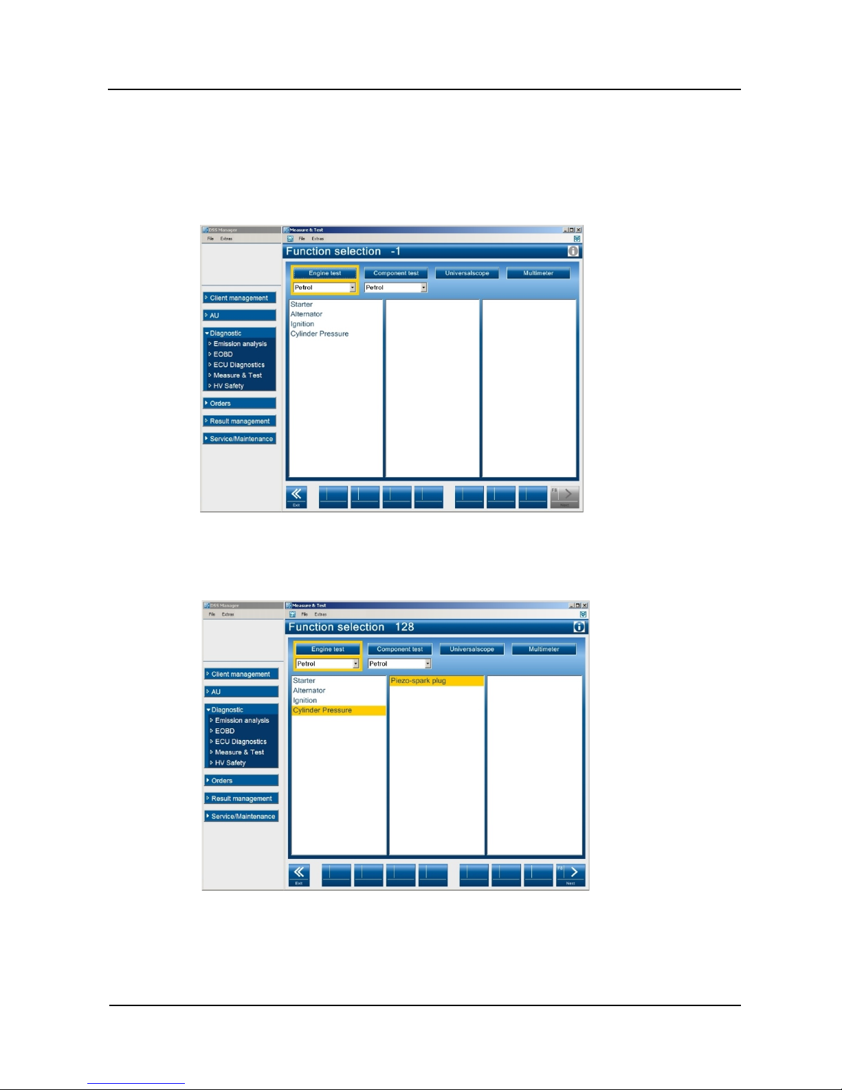
12. Select the mode Diagnostic I Measure & test I Enginetest I Petrol (if testing cylinder
pressure with the piezo-electric pressure-sensing sparkplug)
or Diesel (if testing cylinder pressure with the piezo-electric glow plug pressure sensor
adaptor), see Fig. 3-5.
Fig. 3-5
13. Select the mode Cylinder Pressure I Piezo-spark plug (Piezo- glow plug for diesel
engines), see Fig. 3-6.
Fig. 3-6
14. Click F8 Next.

AVL DiTEST DPM 800
Measuring
User manual
3-5
Enter the TDC offset, if known, and select the number of strokes per engine cycle,
see Fig. 3-7.
Only by entering the correct TDC offset can meaningful readings be obtained.
You can find out the TDC offset.
Proceed as described in Section 3.1.2 "Determining TDC".
Fig. 3-7
Information

Measuring
AVL DiTEST DPM 800
3-6
User manual
15. Click F8 Next. The results of the test are shown.
Fig. 3-8
As well as the internal cylinder pressure (red trace, channel 1)
and the on-board engine speed/TDC signal (blue trace, channel 2),
the following relative readings are shown in the area (A):
Mean pressure, imep:
This is the indicated mean pressure, i.e. essentially it is the averaged surplus pressure
prevailing between 0° and 180° of crankshaft rotation, see (B).
Max. pressure pmax:
The maximum pressure, in the example 7.5 bar, see (C).
pmax/TDC:
The crankshaft angle at which the maximum pressure occurs relative to the engine's TDC. in
the example -0.8° of crankshaft rotation, see (D).
RPM:
The engine speed while taking the pressure readings, in the example 860 rpm.
Ref/TDC:
The TDC offset entered or determined, in the example 20° of crankshaft rotation.
16. To go back, press << Cancel.
(A)
B C D
-

AVL DiTEST DPM 800
Measuring
User manual
3-7
3.1.1 Setting the pressure sensor sensitivity
To obtain optimum representation of the measured data, you have to set the sensitivity of the
piezo-electric pressure-sensing sparkplug (glow plug pressure sensor adaptor).
1. The figures are printed on the top of the
package containing the piezo-electric
pressure-sensing sparkplug (glow plug
pressure sensor adaptor), in the example
shown:
Sensitivity RT
0 – 140 BAR 16.24 pC/BAR
0 – 200 BAR 16.25 pC/BAR
see Fig. 3-9.
Fig. 3-9
2. On the results graph screen (display mode), see Fig. 3-8, click F8 Switching.
3. In the box "bar/mV" enter the rounded figure (see above), in the example shown 16mV
(16.24pC/BAR => 16mV).
Explanation:
The charge amplifier used has a signal voltage/charge ratio of
1mV per pC (pico coulomb).
If the pressure sensor produces a charge of 16.24 pC at 1 bar pressure and the change
amplifier connected generates a signal voltage of 1 mV/pC, then the signal voltage equates
to 16.24 mV per 1 bar of measured pressure.
Fig. 3-10
4. To return to the results graph screen (display mode), Fig. 3-8, click F8 Switching.

Measuring
AVL DiTEST DPM 800
3-8
User manual
3.1.2 Determining TDC
Only by entering the correct TDC offset can meaningful readings be obtained.
See also Fig. 3-7.
Starting from the results screen (display mode), see Fig. 3-8, proceed as follows:
1. Put the engine into non-firing overrunning mode.
- When stationary, that is done by revving the engine to a high speed and then releasing the
accelerator.
- On the road, it is done by driving downhill with your foot off the accelerator.
In addition, if possible, you can also shut off fuel injection into the cylinder being tested by
electrically disabling the fuel injector, e.g. by unplugging the lead.
2. Stop the test by clicking F2 Freeze.
3. Using the button, scroll back to when the cylinder was firing.
You can identify when the cylinder was firing by:
- a high cylinder pressure
- a high engine speed
see Fig. 3-11.
Fig. 3-11
Information

AVL DiTEST DPM 800
Measuring
User manual
3-9
4. Using the button, scroll forwards to when the cylinder was overrunning.
You can identify when the cylinder was overrunning by:
- a low maximum pressure
- a raised engine speed (>2000 rpm)
- a distinctly evident negative pressure following gas expansion after TDC
see Fig. 3-12.
Fig. 3-12
5. Activate TDC detection by clicking .
Green colour indicates: reference marker detected and related to TDC.
Red colour indicates: reference marker not detected,
reference marker could not be related to TDC
(TDC detection could not be completed).
If the reference marker is detected and related to TDC, the internal cylinder pressure is then shown
in correct relation to TDC.

Measuring
AVL DiTEST DPM 800
3-10
User manual
By selecting the option box you can display cursors marking the maximum
pressure and the detected reference marker position of the on-board engine speed/TDC sensor
signal.
Fig. 3-13

AVL DiTEST DPM 800
Measuring
User manual
3-11
3.1.3 Signal representation
The basic signal setting is chosen so that analysable signals are displayed at idling speed.
At higher speeds and loads, the pressure conditions change and the signals behave accordingly.
In order to obtain optimum signal representation for your particular application, proceed as follows:
1. On the results graph screen (display mode), Fig. 3-8, click F8 Switching.
2. Channel 1 (CH1):
Open the drop-down option box "Pressure/Div" and select a suitable pressure.
3. Channel 2:
Open the drop-down option box "Voltage/Div" and select a suitable vol tag e.
In this connection please also refer to the AVL DiScope 802 device manual.
3.1.4 Markings
By selecting the option box you can display cursors marking the maximum
pressure and the detected reference marker position of the on-board engine speed/TDC sensor
signal.
3.1.5 Setting DC offset in bar
Starting from the results screen (display mode), see Fig. 3-8, proceed as follows:
1. Click F8 Switching to change to settings mode.
The default setting is 31.8 bar (it is based on an amplifier offset voltage of 500 mV and an
average pressure sensor sensitivity).
If you take a reading under unpressurised conditions, e.g. with the pressure sensor removed
from the engine but connected, the reading trace should run along the zero line.
2. If that is not the case, you can re-read the offset by clicking .
3. Clicking F8 Switching again returns you to display mode.
Subsequently you can fine-tune the offset while a test is in progress by clicking inside the box
and entering a suitable figure until the neutral-pressure signal status (shortly
before induction pressure status) runs along the zero-bar line.
Information

Measuring
AVL DiTEST DPM 800
3-12
User manual
3.2 Tips on testing
During the starting sequence on petrol engines, the maximum cylinder pressure measured is
distinctly higher than in idling mode.
Due to the throttle being closed and the more dynamic conditions when the engine is running, the
throttle effect is greater, which in turn produces a low maximum pressure.
Example:
While the engine is being started, despite the throttle being closed, the intake air flow is not so
dynamic that it produces high throttle losses.
-> The maximum cylinder pressure is equal to the known final compression.
The throttle losses are different when the engine is idling as the intake air flow is much more
dynamic.
-> The maximum cylinder pressure drops to a substantial degree (e.g. 5 - 6 bar).
3.3 Testing while the car is being driven
Risk of injury
Never take readings when driving the car alone.
(Driver drives, passenger takes readings.)
Route the leads through the car so that they
- do not come into contact with any hot parts
- are not close to any hot parts (radiant heat)
- do not come into contact with any rotating parts
Secure the leads and the AVL DiTEST DPM 800 amplifier in the car.
3.4 AVL DiTEST DPM 800 Connection Box
The AVL DiTEST DPM 800 Connection Box is equipped with a 9V PP3 battery.
Switch off the AVL DiTEST DPM 800 Connection Box after completing the test.
(See also Fig. 3-4, item G.)
WARNING

AVL DiTEST DPM 800
Care and maintenance
User manual
4-1
4 Care and maintenance
4.1 Visual check
Regularly carry out a visual check of the AVL DiTEST DPM 800.
Examine all components for damage (e.g. breakages) and dirt contamination.
Regularly check the AVL DEM 800 amplifier, the piezo-electric pressure-sensing sparkplug, the
piezo-electric glow plug pressure sensor adaptor, the adaptor socket and all leads for damage and
dirt contamination.
4.2 Cleaning
Before cleaning the AVL DiTEST DPM 800, disconnect all leads and switch off the AVL DiTEST
DPM 800 amplifier.
Only clean the AVL DiTEST DPM 800 with a dry cloth.
Do not use any cleaning agents or solvents.
4.3 Replacing the battery
1. Switch off the AVL DiTEST DPM 800 Connection Box at the ON/OFF switch (K).
2. Unscrew the lead to the AVL DiScope 802 (L) from the AVL DiTEST DPM 800 Connection
Box SIGNAL OUT connection and the lead (M) from the AVL DiTEST DPM 800 amplifier.
Fig. 4-1
(M)
(L)
(K)

Care and maintenance
AVL DiTEST DPM 800
4-2
User manual
3. Carefully slide the battery cover (N) on the back of the AVL DiTEST DPM 800 Connection
Box downwards.
Fig. 4-2
4. Take out the battery (O) and disconnect the terminals (P).
Connect a new battery and insert it in the AVL DiTEST DPM 800 power supply unit.
Fig. 4-3
5. Carefully replace the cover, see Section 3, Fig. 4-2.
(N)
(P)
(O)

AVL DiTEST DPM 800
Product specifications
User manual
5-1
5 Product specifi cations
Component
Order number
System consists of:
Station AVL DiX 102 (if not already present)
VS8128
AVL DiTEST DPM 800
VS8755
Consisting of:
Connection Box not includin g 9V PP3 batt er y
BO7725
Battery, 9V, PP3 E
HI0001
AVL DiTEST DPM 800 amplifier
GG1407
Adaptor socket to fit piezo-electric pressure-sensing sparkplug or
glow plug pressure sensor adaptor ordered
E.g. GG7405 or
WG0140 or
WG0200 …
Piezo-electric pressure-sensing sparkplug or glow plug pressure
sensor adaptor ordered
Lead, BNC 0.5m black RG 58
EX7528
DiX software CD
BO7340
DiX manual CD
VM7777

Product specifications
AVL DiTEST DPM 800
5-2
User manual

AVL DiTEST DPM 800
Warranty
User manual
6-1
6 Warranty
6.1 New devices
New devices have a 12-month warranty period.
The batteries have a six-month warranty period.
The agreements with your supplier apply.
Principally wear parts and accessories are excluded from the warranty.
For the execution the date of the shipping note to the final customer does apply.
The warranty expires due to:
■ Mechanical damage (e.g. fall, etc.)
■ Pen etr at ion of moistur e (e. g. water , o il, acids, etc .)
■ External intervention (e.g. repairs carried out by non-authorized people)
■ Improper operation (e.g. control of touch screen with sharp or pointed
object, cleaning with compressed air)
■ Improper storage, care and maintenance (e.g. cleaning the device with solvent-based
cleaners)
6.2 Exchange or loaned devices
The agreements with your supplier apply.
For the execution the date of the shipping note to the final customer does apply.
6.3 Event of damage or loss
In the event of damage or loss, please contact the respective AVL DiTEST office / the respective
AVL DiTEST partner in your country.

Warranty
AVL DiTEST DPM 800
6-2
User manual

AVL DiTEST DPM 800
Technical data
User manual
7-1
7 Technical data
Piezo-electric pressure-sensing
sparkplug
Piezo-electric pressure-sensing
sparkplug:
Sparkplug with integral pressure sensor manufactured to
customer specifications
(Order form – AT7657D/E)
Piezo-electric glow plug pressure
sensor adaptor
Piezo-electric glow plug pressure
sensor adaptor:
Glow plug adaptor with integral pressure sensor
manufactured to customer specifications
(Order form – AT7656D/E)
Adaptor socket
Adaptor socket:
Adaptor socket for fitting the piezo-electric pressuresensing sparkplug with slot for the pressure sensor lead
AVL DiTEST DPM 800
Connection Box
Dimensions (WxHxD):
60x120x20mm
Weight:
Approx. 500g
Operating temperature:
+5 … +35 °C
Transportation temperature:
-25 … +60 °C
Power suppl y:
9V PP3 battery supplied
Connections:
Input:
- SIGNAL IN (piezo-electric pressure-sensing
sparkplug/glow plug pressure sensor adaptor)
Outputs:
- SIGNAL OUT (AVL DiScope 802)
Controls and displays:
Button:
- ON/OFF
LED:
- PWR (blue)

Technical data
AVL DiTEST DPM 800
7-2
User manual
AVL DiTEST DPM 800 amplifier
Input range
6000 pC
Signal ratio
1mV/pC
(1mV output voltage at 1pC coulomb input voltage)
Zero line
0.5 V
Signal variation
0.5 … 4.5V
Linearity
<0.1 %
Frequency response (-3dB)
10 kHz
Error at 20°C
0.25 %
Overall error over complete
temperature range
1 %
Temperature range
-10 … 120 °C
Signal noise
<2 mVpp
Output resistance
<100 Ω
Load resistance
≤500 Ω
Power suppl y voltage
8 … 32 V
Dimensions (length x dia.):
131x13.8mm
Plug
M12
Connections
Input:
- Piezo-electric pressure-sensing sparkplug/glow plug
pressure sensor adaptor
Outputs:
- AVL DiScope 802, CH1 or CH2
CE mark:
CE mark:
The manufacturer hereby declares that the AVL DiTEST
DPM 800 complies with the provisions of the EC Directives
cited below including all relevant am endments:
- EN 61010-1 (Safety Requirements)
- EN 61326-1 (EMC)
- 2006/95/EC Low-voltage Elec tr ic al Equipment Directive
Disposal:
Disposal
This AVL DiTEST product is a high-quality electrical and
electronic device which must not be disposed of as normal
household waste.
For disposal, it is essential to comply with local lega l
obligations!
 Loading...