

Page 1

A V L L O O M S
1
Quantity
Description
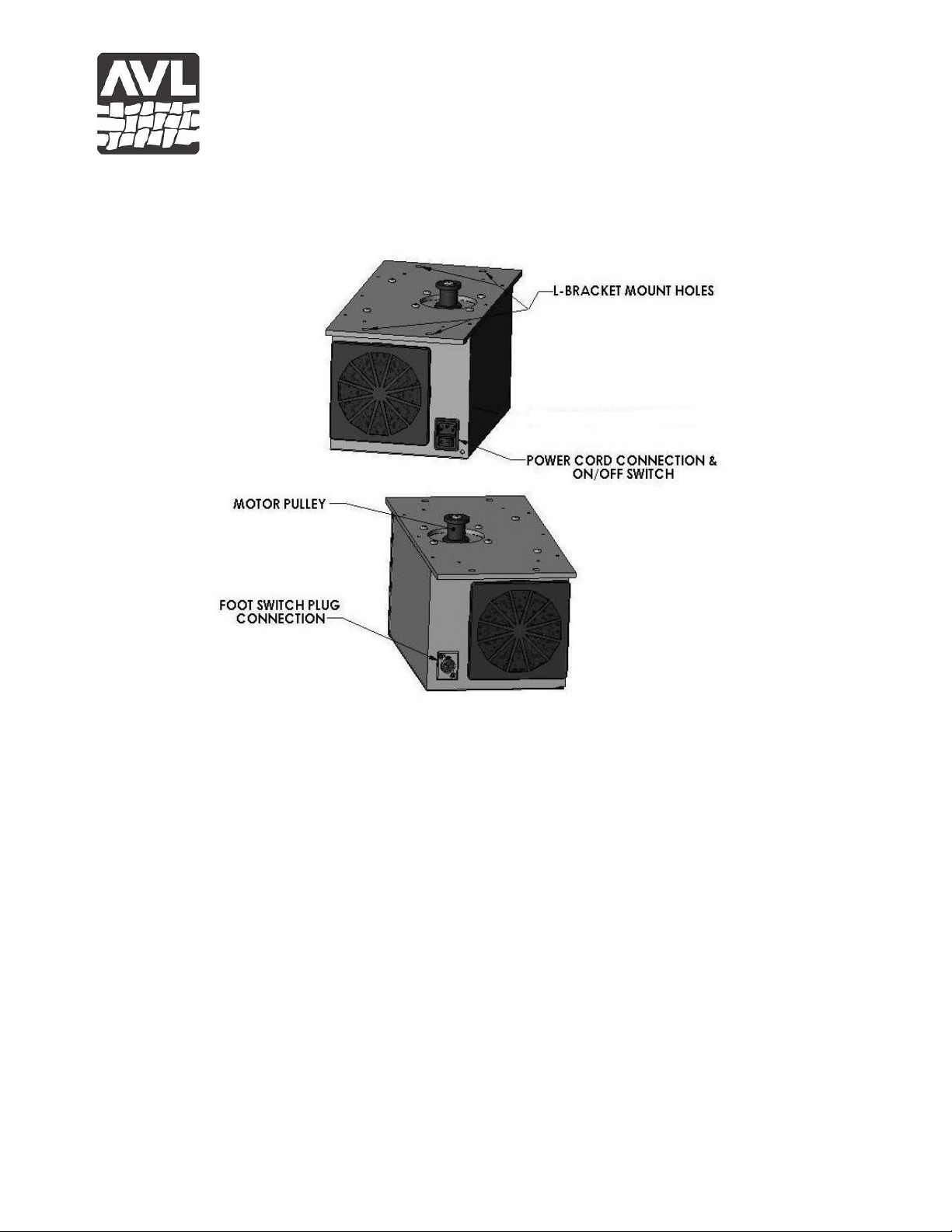
1 E-Lift II+ Motor/ Pulley Box – Fig. 1a, 1b
1 Spring Lever Assembly
1 Spring Lever Stand-off Bushing
1 1/2"OD x 5/16"ID x 3/8" L Bushing
1 # 8350 Spring
2 SDL E-Lift II+ Mount Block
1 Cam/Cylinder Assembly
1 Cord, Motor Pulley to Cam
1 Cord, Dobby Arm to Spring Lever
4 1/2" Stop Collar
1 1/4-20 x 2-5/8" Eye Bolt
1 1/4-20 Hex Nut
1 1/4-20 Nylock Nut
2 1/4 Flat Washers
4 5/16-18 x 2 3/4" Hex Bolt
1 5/16-18 x 3-1/2" Hex Bolt
5 5/16-18 Nylock Nut
12
5/16 Flat Washer
4 5/16-18 x 2 Hex Bolt
4 5/16-18 Square Nut
4 5/16 Split Lock Washer
1 Foot Switch and Attached Cord
1 Power Cord
AVL Looms, Incorporated
2360 Park Avenue, Chico, California 95928-8305
Phone: 530-893-4915 Fax: 530-893-1372 www.avlusa.com
E-LIFT II+ UPGRADE INSTALLATION
FOR STUDIO DOBBY LOOM (SDL)
SUPPORT AND WARRANTY
Congratulations on your purchase of an AVL E-Lift II+, for your Studio Dobby
Loom. Your new E-Lift II+ takes the work out of lifting your harnesses and is designed
to provide years of dependable service.
Your E-Lift II+ comes with a lifetime of phone and e-mail support and a standard AVL
One-Year Warranty for the original owner. For a complete warranty statement, to have
warranty service performed, or to get support, please contact AVL at 530-893-4915 or by
e-mail to [email protected].
INSTALLATION
Package Contents: Note: If, upon your inspection of the contents of your package, all
pieces listed here are not represented, please contact AVL Looms immediately, prior to
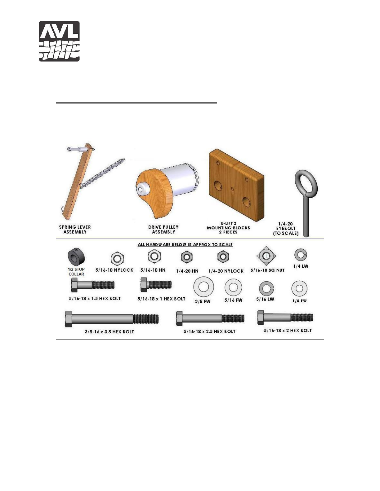
installation. See Figure 2 for help with identification of these components and hardware.
Revision 4/9/14
Page 2
A V L L O O M S
2
AVL Looms, Incorporated
2360 Park Avenue, Chico, California 95928-8305
Phone: 530-893-4915 Fax: 530-893-1372 www.avlusa.com
Figure 1 – E-Lift II+ Motor Box
Required Tools
7/16” and 1/2” Wrench or
Socket Wrench with 7/16” and 1/2” Sockets
5/32” Allen Wrench
Pliers
Drill with 21/64” Bit
Tape Measure
Masking or other type of Tape
Pencil
SDL IMAGES
The vast majority of SDLs made by AVL were configured with a 20” weaving width,
with a few produced with 30” weaving width. The images in this manual reflect the 20”
loom. For the 30” loom, the spring lever return and E-Lift position appear closer to the
center since the mounting of both is fixed from the right side of the loom.
Revision 4/9/14
Page 3
A V L L O O M S
3
AVL Looms, Incorporated
2360 Park Avenue, Chico, California 95928-8305
Phone: 530-893-4915 Fax: 530-893-1372 www.avlusa.com
ORIENTATION**: All directional references are relative the Weaver’s position for
loom operation. This is the Front of the Loom.
PREPARING THE LOOM FOR THE E-LIFT II+
1) Remove the Treadle Assemblies - Disconnect the Left Treadle Cable and remove it
from the Dobby Arm (Keep the black retainer collar for this installation). Disconnect the
Figure 2 – Assembly Components and Hardware Identification
Right Treadle/Cam Cable from the Treadle, but do not disconnect the Cylinder Cable
from the Dobby Arm. Remove your Left and Right Treadle Assembly.
2) Remove the Treadle Cable Axle from the Treadle Pulley Support Crossmembers. If
your axles are fitted with black plastic caps, use pliers to distort and remove them. If
your axles have stop collars at the ends, remove them with the Allen Wrench.
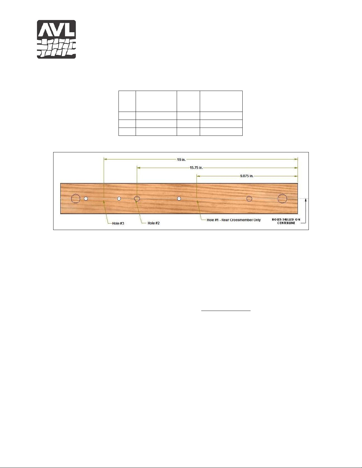
3) Drill Instructions/Hole Orientation (see Figure 3)
Revision 4/9/14
Page 4
A V L L O O M S
4
HOLE
No.
HOLE
ORIENTATION
HOLE
SIZE
DISTANCE
FROM
RIGHT** EDGE
1
Horizontal
21/64"
9-7/8“
2
Horizontal
21/64"
15-3/4"
3
Horizontal
21/64"
19"
AVL Looms, Incorporated
2360 Park Avenue, Chico, California 95928-8305
Phone: 530-893-4915 Fax: 530-893-1372 www.avlusa.com
Check to see if your front and rear Treadle Pulley Support Crossmembers have the
following mounting holes:
Figure 3 – Placement of Drilled Holes
If the three (3) holes are not already present, they will need to be drilled at this time. You
may wish to remove the Crossmembers in order to complete this task. If so, you can
remove the two (2) hex bolts holding each of the Treadle Pulley Support Crossmembers
to your loom. Be sure to mark the left and right sides and the inside and outside face of
both Crossmembers with tape and pencil prior to removing them and place on a suitable
work surface.
Locations for the three (3) holes are measured from the right-side end of the Treadle
Crossmember. Drill any holes that are not already in place (see Figure #3).
Revision 4/9/14
Page 5
A V L L O O M S
5
AVL Looms, Incorporated
2360 Park Avenue, Chico, California 95928-8305
Phone: 530-893-4915 Fax: 530-893-1372 www.avlusa.com
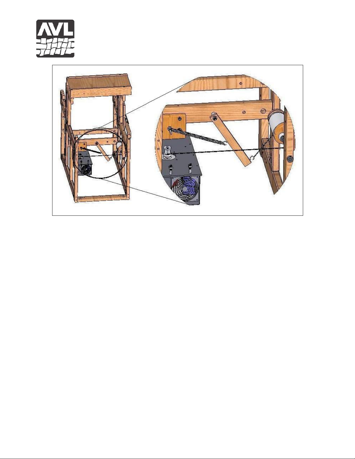
Figure 4 – Mounted Spring Lever Assembly
4) Mount the Spring Lever Assembly – (see Figure 4) Into Hole #1, insert one (1)
5/16–18 x 3-1/2” Hex Bolt with one (1) 5/16 Washer, from the outside of the rear
Crossmember and mount the Spring Lever Assembly onto it, on the inside of the
Crossmember as follows:
1 5/16 Washer
1 Spring Lever Stand-off Bushing
1 5/16 Washer
1 Spring Lever Assembly (bushing taped to Spring Lever;
install with eyehook at the tip facing to the right side of the loom)
1 5/16 Washer
1 5/16–18 Nylock
5) Re-install the Treadle Pulley Support Crossmembers to the loom. Take care to
place them in the same positions as they were previously installed.
6) Install Mounting Blocks – (see Figure 5) Mount the two Blocks onto the top of the E-
Lift Motor Box. Run one (1) 5/16-18 x 2” Hex Bolt, with one (1) 5/16 Split Lock
Washer, up through the flange on the top ends of the Box, into the pre-drilled holes
located at the narrow, bottom end of each Block. Tighten by holding one (1) 5/16 Square
Nut in place, with the flat side down, through the lateral hole provided for access. Note:
the angular corners of the Square Nut will need to bind down, into the wood.
Revision 4/9/14
Page 6
A V L L O O M S
6
AVL Looms, Incorporated
2360 Park Avenue, Chico, California 95928-8305
Phone: 530-893-4915 Fax: 530-893-1372 www.avlusa.com
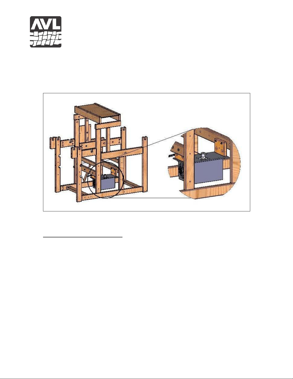
4 5/16-18 x 2” Hex Bolts
4 5/16 Split Lock Washers
4 5/16 Square Nuts
Figure 5 – Motor Box Installed
INSTALLING THE E-LIFT II+
1) Install the E-Lift II+ Motor Box - (see Figure 5) Position the Box underneath and
between the two Crossmembers. Insert the four (4) 5/16-18 x 2-3/4” Hex Bolts, with
washers, from the outside, into the previously drilled Holes #2 and #3, just far enough to
keep them from falling out, while not protruding into the central area. Position the Box
in the space between the Crossmembers, so that the Plug Connection for the Pedal faces
to the Front and the Motor Box Pulley is closest to the Left Side of the loom. Lift the
Box into place and push the Mounting Block Bolts all the way through the Blocks and
tighten in place with one (1) 5/16 Washer and one (1) 5/16 Nylock on each Bolt.
4 5/16-18 x 2-3/4” Hex Bolts
8 5/16 Washers
4 5/16 Nylock
2) Mount the Spring Assembly – (see Figure 4) On the inside of the loom, into the hole
located in the mid-section of the rear Mounting Block, insert the 1/4-20 x 2-5/8 Eye Bolt,
with one (1) 1/4-20 Hex Nut and one (1) 1/4" Washer. Secure it, on the outside of the
Revision 4/9/14
Page 7

A V L L O O M S
7
AVL Looms, Incorporated
2360 Park Avenue, Chico, California 95928-8305
Phone: 530-893-4915 Fax: 530-893-1372 www.avlusa.com
Mounting Block, with one (1) 1/4" Washer and one (1) 1/4" Nylock. Stretch the #8350
Spring from the Eye Bolt to the Eye Hook centered on the facing side of the Spring
Lever.
1 1/4-20 x 2-5/8 Eye Bolt
1 1/4-20 Hex Nut
2 1/4" Washers
1 1/4" Nylock
1 8350 Spring
3) Remove the Original Cam-Pulley Assembly – Loosen the right-hand stop collar
located on the Cam-Pulley Axle on your loom. Pulling to your left, withdraw the axle
and remove the Cam-Pulley Assembly and Left Treadle Pulley.
Disconnect the Dobby Arm/Cylinder Cable from the Cylinder, leaving it attached
to the Dobby Arm. Use a sley hook to reach into the side hole and pull out the retainer,
allowing the Cable to slip free of the Cylinder.
4) Replace Cam-Pulley Axle – (see Figure 6) Attach the Dobby Arm Cable to the new
Cylinder, using the retainer to hold the Nico tip in place on the new Cylinder. Starting
from your left, insert the Axle through Leg “A” so the end extends a few inches into the
middle space between Legs “A” and “B”. As seen in Figure 4 and in this order, slide the
following components onto the Axle:
a. 1 1/2" Stop Collar
b. 1 Cam/Cylinder Assembly
c. 2 1/2" Stop Collars
d. 1 Left Treadle Pulley
e. 1 1/2" Stop Collar
Then slide the Axle through Leg “B” and replace the right-hand Stop Collars on the end
of the Axle.
Revision 4/9/14
Page 8
A V L L O O M S
8
AVL Looms, Incorporated
2360 Park Avenue, Chico, California 95928-8305
Phone: 530-893-4915 Fax: 530-893-1372 www.avlusa.com
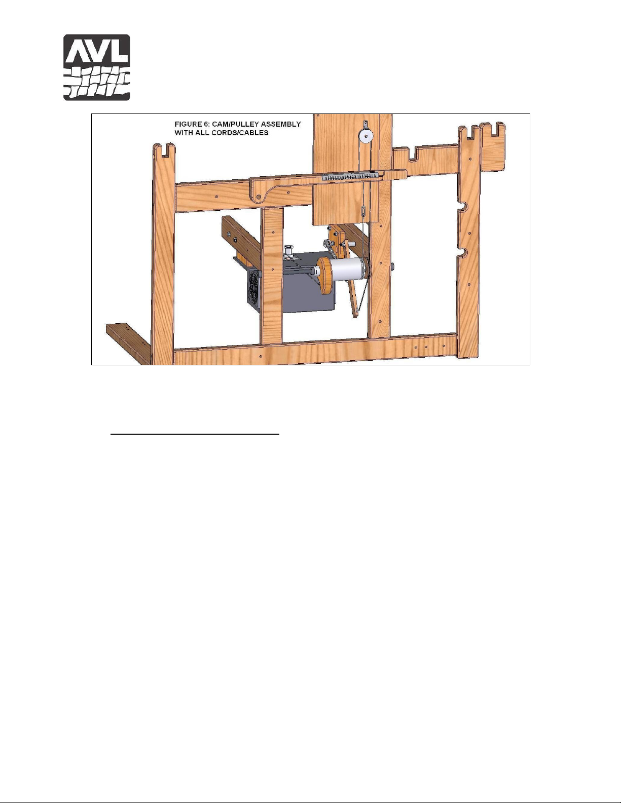
Figure 6 – Cables installed
5) Installing the Cables (see Figure 6)
5a) The Spring Lever Return Cable – In order to install this cable, it will be necessary
to remove the Compu-Dobby from the loom. Follow steps 1–8 below before proceeding
with the installation of the cable. Please refer to your Compu-Dobby Manual for further
information, as well as for reinstallation, and adjustment.
1. Turn off the Compu-Dobby.
2. Unplug the Sensor Box from the Compu-Dobby or detach it from the Mount Box, in
order to be able to extract the Compu-Dobby completely from the Mount Box.
3. Using a Phillips screwdriver remove the two (2) screws that hold each Plate in place.
Be aware that there is a small spring behind each Set Screw which will gently push the
box out as the Retainer Plates are removed.
4. Lift the Box free of the Mount and set it aside. Be sure to catch the two springs held
in place between the Pillow Blocks and the back of the Mounting Box. They are only
held in place by the positioning of the Compu-Dobby Box and will probably fall free
when it is removed.
5. Lift a few of the hanging Dobby Fingers now exposed and you will have clear access
to the Pulley and Retainer mounted in the upper right corner of the Mounting Box.
Revision 4/9/14
Page 9

A V L L O O M S
9
AVL Looms, Incorporated
2360 Park Avenue, Chico, California 95928-8305
Phone: 530-893-4915 Fax: 530-893-1372 www.avlusa.com
6. When the Spring Lever Return Cable is in place, refer to Pages 5 and 10 of your
Compu-Dobby Manual for re-installation, and Page 21 for Adjustment procedure.
Installation of the Spring Lever Return Cable (continued) - Note the opening in the
Dobby Arm through which the Left Treadle Cable is attached. Remove the old cable by
pushing down on the cable until the plastic cable retainer button falls from the bottom of
dobby arm. Save the plastic cable retainer button for later. Remove the old Cable from
the Dobby Arm by pulling it up through the dobby arm.
From the top side of the Dobby Arm, insert the new cable through the hole in the
Dobby Arm, previously used by the Left Treadle Cable and secure it with the plastic
cable retainer button saved from the old cable removal. Route the cable over the top of
the Dobby Box Pulley, from left to right, and under the cable retainer. Guide the cable
behind the Dobby Bar, down the outside of the loom, and around the bottom of the Lever
Pulley (formerly the Left Treadle Pulley). Connect the looped end of the cable to the
Spring Lever, using the Eyehook located at the tip of the Lever.
Check to see that the cable is running in a direct line from the right side of the
Dobby Box pulley straight down to the Lever Pulley and on over to the Lever. Loosen
the stop collars to either side of the Pulley and adjust the position as needed.
5b) The Cam-Motor Pulley Cable – Check to be sure the Dobby Arm is in the Up
Position before proceeding. Unwrap the cable from the 6 inch diameter wooden Cam.
Guide the cable down and around the bottom of the Cam, over to the Pulley located on
top of the Motor Box. Bring the cord around the left, front side of the Motor Pulley.
Insert its end into the hole you see at the base of the Pulley and lock the crimp in the hole
with the hitch pin. (Note: do not use the hole located at the top of the Pulley). Turn the
Pulley clockwise, while starting at the bottom, winding on and taking up all of the slack.
Do not allow the winding to overlap.
The two cables on the Cam/Cylinder Assembly need to align directly with their
respective anchor points. The Dobby Arm Cable must run vertically from the Dobby
Arm to the Cylinder and the Cam/Motor Pulley cable needs to run in a direct line from
the Cam to the Motor Pulley on the top of the E-Lift II+ Motor Box. In order to
accomplish this, with the respective stop collars loosened, slide the Cam and Pulley into
place along the Axle and tighten the Stop Collars.
6) Connect the Foot Switch Cord and the Power Cord – (See Figure #1a, 1b) Connect
the Foot Switch Cord to the front of the E-Lift II+. Connect the female end of the Power
Cord at the back of the housing (be sure it is completely, firmly inserted). Turn off the ELift Power Switch. Plug the male end of the Power Cord into a surge-protected power
strip or directly into a wall plug.
Revision 4/9/14
Page 10

A V L L O O M S
10
AVL Looms, Incorporated
2360 Park Avenue, Chico, California 95928-8305
Phone: 530-893-4915 Fax: 530-893-1372 www.avlusa.com
ADJUSTING TO THE “HOME” POSITION
The E-Lift II+ replicates the action of treadling. When you activate the Foot Switch, the
motor turns and selected harnesses rise or fall. The motion is smooth, quick, and precise
and does not jar the harnesses.
In order for the E-Lift to function properly, your last step is to set the “home” or
neutral position.
1) Turn off the E-Lift II+ power switch. Unwind the E-Lift II+ Motor Pulley cable to
allow the Dobby Arm to move to its uppermost position.
2) Rewind the E-Lift II+ Motor Pulley, bringing the Dobby Arm to a stop approximately
1/4" above the ball on the rear most Dobby Cable.
SELECTION OF WEAVING MODE (see Figure 1)
The E-Lift II+ is programmed with two shed lifting modes: double or single shed. At
power on, the E-Lift defaults to double shed mode. Switching between the two modes is
accomplished by pressing and holding the foot pedal for a slow count of ten.
The Double Shed Mode, with one pedal action on your part, will complete every lifting
cycle, beginning and ending with the open shed. For example, assume you have just
completed a shot and the shed is still open. You depress the foot switch and the shed
closes, the dobby advances to the next pick, and the shed opens – all as a single,
continuous movement. You will very quickly develop a rhythm and will find there is
ample time to beat while the shed is transitioning the Open-Close-Open Cycle.
The Single Shed Mode will require two pedal actions, on your part, to complete the
cycle: once to open the shed, and once to close the shed.
CONGRATULATIONS!
Turn on the E-Lift Power Switch. You are ready to weave!
MAINTENANCE AND REPLACEMENTS
1) With Each Startup Maintenance
Set home position as discussed in Adjusting to the “Home” Position section of the
manual.
2) Regularly Required Maintenance
You will need occasionally to clean the air filters, which are located on the front and back
of the E-Lift II+ housing. To clean, unsnap and remove the plastic baffle/covers.
Revision 4/9/14
Page 11

A V L L O O M S
11
AVL Looms, Incorporated
2360 Park Avenue, Chico, California 95928-8305
Phone: 530-893-4915 Fax: 530-893-1372 www.avlusa.com
Remove the foam elements and carefully wash them in warm soapy water. Be sure the
elements are completely dry before you replace them.
3) Suggested Monthly Maintenance
a) Inspect the cables for wear, especially where they move over a pulley. Do this on a
monthly basis if you weave regularly.
b) Check the supporting hardware and re-tighten if loose.
Your E-Lift II+ is designed to provide years of dependable service. When replacement
parts, such as the air filter or cables are needed, AVL is your source. AVL can also
rebuild your E-Lift II+ when it reaches the end of its wear cycle. Please contact us at
530-893-4915 or http://www.avlusa.com/contact-us/ to place your order, arrange service
or answer any questions you may have regarding this product.
Revision 4/9/14
 Loading...