

ENGINE DIAGNOSTICS
AVL LIST GMBH
Hans-List-Platz 1
A-8020 Graz / Austria
Phone: +43 316 787-0
Fax: +43 316 787-550
http://www.avl.com
Ident. number: AT0391E
Revision no.: 04
Edition: January 1999
Subject to alteration
Printed in Austria by
AVL LIST GMBH Graz
Service Manual
A VL DiGas 4000
AVL DiCom 4000
AVL DiSmoke 4000

Copyright 1999 AVL List GmbH, all rights reserved.
The contents of this document may not be reproduced in any form or communicated to
any third party without the prior written consent of AVL.
While every effort is made to ensure correctness, AVL assumes no liability for errors and
omissions.
Important Notice! – Important Notice!
This manual contains important warnings and safety instructions to be observed
by the user.
The product described is intended for only one certain area of application which is
prescribed in the instructions. Furthermore, the manual explains the critical
prerequisites for application and operation as well as the safety measures to ensure
smooth operation. No warranty is granted or liability accepted if the prerequisites and
safety measures are not met.
The product is to be operated and used only by qualified personnel capable of
observing the required safety precautions. Only accessories and expendables either
supplied or approved by AVL are to be used with the product.
Due to the operating principle of this product, the accuracy of the measurement
results it produces not only depends on its correct operation and function but also
upon a variety of peripheral conditions beyond the control of the manufacturer. The
results obtained from this product must therefore be subjected to careful examination
by an expert (e.g. for plausibility) before any action is taken that is based on the
results.
Adjustments to and maintenance of devices when open and under voltage are only
to be carried out by a professional technician who is aware of the dangers involved.
Repairs to the product are to be carried out by the manufacturer or qualified service
personnel only.
When the product is used, a technical expert must ensure that neither the test object
nor the testing equipment is operated under conditions that may lead to damage or
injury.
LIST GmbH
Important Notice! – Important Notice!

Safety Instructions for Handling O2 and NO Sensors
The O2 and NO sensors are supplied fully sealed and under norma l circumstances do not
represent any hazard to health.
The following instructions apply in the event of a sensor developing a leak.
• Before you remove a sensor from the gas-tight original packaging, check it for leaks.
• If you detect damage caused by a leak, always av oid contact with the skin.
• In this event, use rubber gloves and goggles.
The O
are hazardous to health (e.g. caustic potash solution and lead).
When replacing sensors, check both the old and the new one for
leaks.
and NO sensors contain caustic and other substances that
2
First Aid
• Contact with the eyes
− Rinse eyes with water for at least 15 minutes - consult a doctor immediately.
• Contact with the skin
− Remove contaminated clothing immediately.
− Wash the affected pa rt of the body thoroughly with water.
− If a burning sensation is felt on the skin, consult a doctor immediately.
• Swallowing
− Drink a lot of cold water.
− Consult a doctor immediately.


4000 Table of Contents
Table of Contents
1. Periodic Maintenance
1.1 General......................................................................................................................................................1-1
1.2 Maintenance Plan.................................................................................................................................... 1-2
1.3 Minor Maintenance.................................................................................................................................1-4
1.3.1 AVL DiGas 4000.............................................................................................................................1-4
1.3.2 AVL DiSmoke 4000........................................................................................................................1-5
1.3.3 AVL DiCom 4000...........................................................................................................................1-6
1.4 Major Maintenance.................................................................................................................................1-8
1.4.1 AVL DiGas 4000.............................................................................................................................1-8
1.4.2 AVL DiSmoke 4000........................................................................................................................1-9
1.4.3 AVL DiCom 4000...........................................................................................................................1-10
2. Error Messages and Troubleshooting
2.1 4-/5-Gas Measuring Instruments Unit.................................................................................................2-1
2.1.1 Gas Flow Insufficient....................................................................................................................2-1
2.1.2 System Needs Restarting.............................................................................................................. 2-2
2.1.3 Measuring Chamber Temperature Too High.............................................................................2-2
2.1.4 Measuring Chamber Pressure Wrong.........................................................................................2-3
2.1.5 Leak Test Failed .............................................................................................................................2-3
2.1.6 Replace O
2.1.7 Replacing the NO Sensor..............................................................................................................2-4
2.2 Opacity Measuring Chamber................................................................................................................2-5
2.2.1 Measuring Chamber Too Hot/Too Cold....................................................................................2-5
2.2.2 Changeover Valve Error...............................................................................................................2-5
2.3 Linearity / Opacity Error,......................................................................................................................2-6
2.3.1 Opacity Measuring Chamber, Type A........................................................................................2-6
2.3.2 Opacity Measuring Chamber, Type 4000...................................................................................2-6
Sensor..........................................................................................................................2-4
2
3. Software
3.1 General......................................................................................................................................................3-1
3.2 Installation of Operating Software (Software update)....................................................................... 3-4
4. Evaluation Unit
4.1 General Description................................................................................................................................4-1
4.1.1 Basic Design...................................................................................................................................4-2
4.1.2 Evaluation Unit..............................................................................................................................4-3
4.1.3 Pneumatics Rear Panel / 4-/5-Gas Measuring Instruments Unit (5-Gas Option)................4-4
4.2 Hardware Setup......................................................................................................................................4-5
4.2.1 Main Board.....................................................................................................................................4-5
4.2.1.1 Digital System............................................................................................................................4-5
4.2.1.2 Analogue Data Acquisition......................................................................................................4-5
4.2.1.3 Remote Control Receiver..........................................................................................................4-5
4.2.1.4 Interfaces.....................................................................................................................................4-6
4.2.1.5 Display Control and Softkey Connection...............................................................................4-7
4.2.1.6 Generation of Auxiliary Voltage..............................................................................................4-7
4.2.1.7 Board Control.............................................................................................................................4-7
Service Manual I

Table of Contents AVL 4000
4.2.1.8 Printer Board (Option)..............................................................................................................4-8
4.2.1.9 Speed / Angle Board with Diagnostics Cable Concept (Option/Installation) .................4-8
4.2.1.10 Memory Adapter.......................................................................................................................4-11
4.2.1.11 Chamber Adapter (AVL DiCom 4000)....................................................................................4-11
4.2.1.12 Extension Slot.............................................................................................................................4-11
4.2.1.13 Mains Switch Assembly............................................................................................................4-11
4.2.1.14 Converting 230 V to 115 V Device...........................................................................................4-11
4.2.1.15 Power Supply Unit....................................................................................................................4-11
4.2.1.16 Fan...............................................................................................................................................4-12
4.3 Dismantling the 4-/5-Gas Measuring Instruments Unit....................................................................4-12
4.4 Housing....................................................................................................................................................4-12
4.5 Printer.......................................................................................................................................................4-13
4.5.1 Internal Printer Unit (Option/Installation)................................................................................4-13
4.5.2 External A4 Printer (Option)........................................................................................................4-14
4.6 LCD...........................................................................................................................................................4-14
4.7 Membrane Keypad.................................................................................................................................4-14
4.8 Fan............................................................................................................................................................. 4-14
4.9 Main Board...............................................................................................................................................4-15
4.9.1 Components Location Diagram...................................................................................................4-15
4.9.2 Circuit Diagrams...........................................................................................................................4-16
4.10 Speed Angle Board .................................................................................................................................4-21
4.10.1 Components Location Diagram...................................................................................................4-21
4.10.2 Circuit Diagrams ...........................................................................................................................4-22
4.11 Pneumatics Board....................................................................................................................................4-26
4.11.1 Components Location Diagram...................................................................................................4-26
4.11.2 Circuit Diagram.............................................................................................................................4-27
4.12 Printer Adapter........................................................................................................................................4-28
4.12.1 Components Location Diagram...................................................................................................4-28
4.12.2 Circuit Diagram.............................................................................................................................4-29
4.13 Memory Adapter.....................................................................................................................................4-30
4.13.1 Components Location Diagram...................................................................................................4-30
4.13.2 Circuit Diagram.............................................................................................................................4-31
4.14 Connector Adapter.................................................................................................................................4-32
4.14.1 Components Location Diagram...................................................................................................4-32
4.14.2 Circuit Diagram.............................................................................................................................4-33
4.15 Chamber Adapter (opacity measuring chamber type A)..................................................................4-34
4.15.1 Components Location Diagram...................................................................................................4-34
4.15.2 Circuit Diagram.............................................................................................................................4-35
4.16 Receiver Board (opacity measuring chamber type A)........................................................................4-36
4.16.1 Components Location Diagram...................................................................................................4-36
4.16.2 Circuit Diagram.............................................................................................................................4-37
4.17 Selenium Board (opacity measuring chamber type A)......................................................................4-38
4.17.1 Components Location Diagram...................................................................................................4-38
4.17.2 Circuit Diagram.............................................................................................................................4-39
II Service Manual

4000 Table of Contents
4.18 Chamber Adapter (opacity measuring chamber 4000)......................................................................4-40
4.18.1 Components Location Diagram...................................................................................................4-40
4.18.2 Circuit Diagram.............................................................................................................................4-41
4.19 Transmitter Board (opacity measuring chamber 4000)......................................................................4-42
4.19.1 Components Location Diagram...................................................................................................4-42
4.19.2 Circuit Diagram.............................................................................................................................4-43
4.20 Receiver Board (opacity measuring chamber 4000) ...........................................................................4-44
4.20.1 Components Location Diagram...................................................................................................4-44
4.20.2 Circuit Diagram.............................................................................................................................4-45
4.21 Fan Board (opacity measuring chamber 4000).................................................................................... 4-46
4.21.1 Components Location Diagram...................................................................................................4-46
4.21.2 Circuit Diagram.............................................................................................................................4-47
4.22 Wiring Diagrams.....................................................................................................................................4-48
4.23 Internal Cabling.......................................................................................................................................4-51
4.24 4-/5-Gas Section......................................................................................................................................4-52
4.24.1 Pneumatics Board..........................................................................................................................4-52
4.24.2 Multi-gas Measuring System - General Requirements.............................................................4-52
4.25 Service Mode...........................................................................................................................................4-54
4.25.1 Changing O
and NO Sensor.......................................................................................................4-54
2
4.25.2 Gas Calibration..............................................................................................................................4-54
4.25.3 4-/5-Gas..........................................................................................................................................4-54
4.25.4 Diesel - Opacity Measuring Chamber Type A ...........................................................................4-60
4.25.5 Diesel - Opacity Measuring Chamber 4000...............................................................................4-62
5. 4-/5-Gas Measuring Instruments Unit
5.1 General......................................................................................................................................................5-1
5.2 Gas Analyzer...........................................................................................................................................5-2
5.2.1 Light Source...................................................................................................................................5-3
5.2.2 Motor Unit......................................................................................................................................5-3
5.2.3 Measuring Cell...............................................................................................................................5-4
5.2.4 Filter/Receiver...............................................................................................................................5-4
5.2.5 Pressure Sensor..............................................................................................................................5-4
5.2.6 Main Board and Lambda Piggyback ..........................................................................................5-5
5.2.7 Causes of Error..............................................................................................................................5-5
5.3 Layout of Pneumatics.............................................................................................................................5-5
5.3.1 Solenoid.......................................................................................................................................... 5-7
5.3.2 Valve Unit.......................................................................................................................................5-7
5.3.3 Particulate Filter ............................................................................................................................5-7
5.3.4 Pump...............................................................................................................................................5-8
5.3.5 Pressure Sensor..............................................................................................................................5-9
5.3.6 Pneumatics Board..........................................................................................................................5-9
5.4 Power Supply Unit for 4-/5-Gas Measuring Instruments Unit........................................................5-10
5.5 Power Supply Board...............................................................................................................................5-10
Service Manual III

Table of Contents AVL 4000
5.6 O2 Sensor and NO Sensor.......................................................................................................................5-10
5.6.1 Replacing the O
5.6.2 Replacing the NO Sensor..............................................................................................................5-11
5.7 Cleaning the Condensate Part of the 4/5-Gas Bench.........................................................................5-12
5.8 Error Symptom List - Remedies............................................................................................................5-14
Sensor................................................................................................................5-11
2
6. Opacity Measuring Chamber Type A
6.1 System Check with Filter........................................................................................................................6-1
6.2 Upgrading an AVL DiGas 4000 to an AVL DiCom 4000....................................................................6-3
6.3 General Configuration............................................................................................................................6-4
6.4 Dismantling the Opacity Measuring Chamber...................................................................................6-6
6.4.1 Housing Cover 1 (on Exhaust Gas Outlet Side)........................................................................6-6
6.4.2 Housing Cover 2 (on Exhaust Gas Inlet Side) ...........................................................................6-7
6.4.3 Half-shells 1 and 2.........................................................................................................................6-9
6.5 Fans...........................................................................................................................................................6-12
6.6 Heating Blocks and Orifice Plates.........................................................................................................6-13
6.7 Changeover Valve with Geared Motor.................................................................................................6-15
6.8 Temperature Sensor................................................................................................................................6-17
6.9 Lamp Module (BO1135) .........................................................................................................................6-19
6.10 Detector (BO1134)...................................................................................................................................6-21
6.11 Purging Air Panels (YM2691)................................................................................................................6-23
6.12 Electrical Wiring......................................................................................................................................6-24
6.13 Reassembly of the Opacity Measuring Chamber................................................................................6-32
7. Opacity Measuring Chamber 4000
7.1 System Check with Filter........................................................................................................................7-1
7.2 Upgrading an AVL 4000 DiGas to an AVL 4000 DiCom..................................................................7-2
7.3 Assembling and Disassembling the Opacity Measuring Chamber..................................................7-4
7.4 Design and Details of Assemblies.........................................................................................................7-5
7.4.1 Fan Unit (BO2189)......................................................................................................................... 7-5
7.4.2 Measurement Cell (BO2138)........................................................................................................7-6
7.4.2.1 Replacing the Temperature Sensor in the Heating System..................................................7-6
7.4.3 Valve Unit (BO2139)......................................................................................................................7-7
7.4.3.1 Replacing the Temperature Sensor..........................................................................................7-7
7.4.4 Transmitter and Detector Unit.....................................................................................................7-8
7.4.4.1 Checking the Light Sources (green LEDs) and the Receiver ...............................................7-8
7.4.4.2 Checking the Reference Receiver............................................................................................7-8
7.5 Assembling the Opacity Measuring Chamber....................................................................................7-10
8. Spare Parts Lists
8.1 General......................................................................................................................................................8-1
8.2 Standard List............................................................................................................................................8-2
8.3 AVL 4000 with Opacity Measuring Chamber Type A........................................................................8-6
8.4 AVL 4000 with Opacity Measuring Chamber Model A France.........................................................8-10
9. Tools for the Service Technician
IV Service Manual
4000 Periodic Maintenance
1. Periodic Maintenance
1.1 General
This Service Manual describes the following instruments:
− AVL DiGas 4000 (= AVL DiTest 5400)
− AVL DiSmoke 4000 (= AVL DiTest 5430)
− AVL DiCom 4000 (= AVL DiTest 5460)
Some areas are described in detail in the respective Operating Manual and therefore not
dealt with in this Service Manual.
We therefore advise always using the Service Manual
together with the respective Operating Manual.
Service Manual 1-1
Periodic Maintenance AVL 4000
1.2 Maintenance Plan
To ensure that the te ster always functions properly, maintenance must be carried out at
regular intervals.
Maintenance work
Leak test
Filter replacement
Pre-filter on probe
Particulate filter
Condensate filter
Activated carbon filter
Cleaning
Daily
Weekly
One a year
Six-monthly
(minor maintenance)
(major maintenance)
Comment
Automatically required
by tester every day
Replace in good time
when soiled by HC
vapour (e.g. petrol
vapour).
Entry in main-
tenance log book
Probe and hose
Condensate pump
(cleaning kit)
Calibration with calibrating
gas
Replacing O2 sensor
Replacing NO sensor Replacement is
Visual check of outside
Check using software
Software update (as required)
Open tester, visual inspection
of PCBs, clean, close housing,
seal with service seal
as per statutory requirements
see Operating Manual
see Operating Manual
Replacement is
requested by tester
requested by tester
Service engineer
Service engineer
Service engineer
1-2 Service Manual
4000 Periodic Maintenance
Maintenance work
Opacity measuring chamber
type A
Visual check
(silicon seal, leaks in
housing, housing
components, closure
fittings, snap mechanism
of the optical elements,
electrical connections,
probe connection plate
O-ring, electrical cables,
soiling of measuring
chamber and purging air
channel)
Daily
Weekly
Six-monthly
Comment
One a year
(major maintenance)
(minor maintenance)
Entry in main-
tenance log book
Function check (fans,
heating, changeover
valve)
Cleaning of optical
elements
Linear check
Change lamps
Opacity measuring chamber
type 4000
Visual check
(silicon seal, leaks in
housing, housing
components, closure
fittings, snap mechanism
of the optical elements,
electrical connections,
electrical cables)
Function check (fan,
heating, changeover
valve)
Cleaning of optical
elements
Linear check
Service Manual 1-3

Periodic Maintenance AVL 4000
1.3 Minor Maintenance
1.3.1 AVL DiGas 4000
•
Evaluation unit
Check using software
− Raw data from 4-/5-gas measuring instruments unit OK?
− O
sensor is OK?
2
− NO se nsor is OK?
Visual check of outside
Entry in maintenance log book
• Cleaning
Replace particulate filter
(see section 5.3.3 Particulate Filter)
Check O-ring paper filter
Visual inspection of probe and hose
Function check
− Leak test
(see Operating Manual)
− Gas calibration
(see Operating Manual)
1-4 Service Manual

4000 Periodic Maintenance
1.3.2 AVL DiSmoke 4000
•
Evaluation unit
Visual inspection
Enter in maintenance log book
• Opacity measuring chamber, type 4000
Visual check
− Silicon seal
− L eaks in housing
− Housing c ompone nts (cracks, faults)
− C losure f ittings, snap mechanism of optical elements
− E lectrical plug connections and cables
− Probe hose, probe clamp
Function check
(each test is described in the Operating Manual)
− Test function of fan
− Test function of heating
− Check cha ngeover va lve
− Clean the optical elements (by wiping)
− Linear check
Service Manual 1-5

Periodic Maintenance AVL 4000
1.3.3 AVL DiCom 4000
•
Evaluation unit
Check using software
− Raw data from 4-gas measuring instruments unit OK?
− O
sensor is OK?
2
− NO se nsor is OK?
Visual inspection
Enter in maintenance log book
• Cleaning
Replace particulate filter
(see section 5.3.3 Particulate Filter)
Check O-ring paper filter
Visual inspection of probe and hose
• Opacity measuring chamber type A
Visual check
− Silicon seal
− L eaks in housing
− Housing c ompone nts (cracks, faults)
− C losure f ittings, snap mechanism of optical elements
− E lectrical plug connections and cables
− Probe connection plate O-ring
− Probe hose, probe clamp
− S oiling of measuring chamber, purging air channel
Function check
(each test is described in the Operating Manual)
− Test function of fans
− Test function of heating
− Check cha ngeover va lve
("Calibration", "Test", "Deactivate" settings - visual check or diesel service mode)
− Clean the optical elements (by wiping)
− Linear check
1-6 Service Manual

4000 Periodic Maintenance
• Opacity measuring chamber type 4000
Visual check
− Silicon seal
− L eaks in housing
− Housing c ompone nts (cracks, faults)
− C losure f ittings, snap mechanism of optical elements
− E lectrical plug connections and cables
− Probe hose, probe clamp
Function check
(each test is described in the Operating Manual)
− Test function of fan
− Test function of heating
− Check cha ngeover va lve
− Clean the optical elements (by wiping)
− Linear check
Function test
− Leak test
(see Operating Manual)
− Gas calibration
(see Operating Manual)
Service Manual 1-7

Periodic Maintenance AVL 4000
1.4 Major Maintenance
1.4.1 AVL DiGas 4000
•
Evaluation Unit
Check using software
− Raw data from 4-gas measuring instruments unit OK?
− O
sensor is OK?
2
− NO sensor is OK?
Open evaluation unit (remove cover)
Visual inspection, clean pcb
If necessary update setpoint data and software
Close housing, seal with service seal
Enter in maintenance log book
• Cleaning
Replace particulate filter
(see section 5.3.3 Particulate Filter)
Check O-ring paper filter
Visual inspection probe and hose
Clean condensate pump
(using cleaning kit)
Function test
− Leak test
− Gas calibration
1-8 Service Manual

4000 Periodic Maintenance
1.4.2 AVL DiSmoke 4000
•
Evaluation unit
Open evaluation unit (remove cover)
Visual inspection, clean pcb
If necessary update setpoint data and software
Close housing, seal with service seal
Enter in maintenance log book
• Opacity measuring chamber
Visual check
− Silicon seal
− L eaks in housing
− Housing c ompone nts (cracks, faults)
− C losure f ittings, snap mechanism of optical elements
− E lectrical plug connections and cables
− Probe hose, probe clamp
− S oiling of measuring chamber, purging air channel
Function check
(each test is described in the Operating Manual)
− Test function of fan
− Test function of heating
− Check cha ngeover va lve
− Clean the optical elements (by wiping)
− Linear check
• Cleaning
Visual inspection probe and hose
Service Manual 1-9

Periodic Maintenance AVL 4000
1.4.3 AVL DiCom 4000
•
Evaluation unit
Check using software
− Raw data from 4-gas measuring instruments unit OK?
− O
sensor is OK?
2
− NO sensor is OK?
Open evaluation unit (remove cover)
Visual inspection, clean pcb
If necessary update setpoint data and software
Close housing, seal with service seal
Enter in maintenance log book
• Opacity measuring chamber type A
Visual check
− Silicon seal
− L eaks in housing
− Housing c ompone nts (cracks, faults)
− C losure f ittings, snap mechanism of optical elements
− E lectrical plug connections and cables
− Probe connection plate O-ring
− Probe hose, probe clamp
− S oiling of measuring chamber, purging air channel
Function check
(each test is described in the Operating Manual)
− Test function of fans
− Test function of heating
− Check cha ngeover va lve
("Calibration", "Test", "Deactivate" settings - visual check or diesel service mode)
− Clean the optical elements (by wiping)
− Cha nge la mps
− Linear check
1-10 Service Manual

4000 Periodic Maintenance
• Opacity measuring chamber type 4000
Visual check
− Silicon seal
− L eaks in housing
− Housing c ompone nts (cracks, faults)
− C losure f ittings, snap mechanism of optical elements
− E lectrical plug connections and cables
− Probe hose, probe clamp
− S oiling of measuring chamber, purging air channel
Function check
(each test is described in the Operating Manual)
− Test function of fans
− Test function of heating
− Check cha ngeover va lve
− Clean the optical elements (by wiping)
− Linear check
• Cleaning
Replace particulate filter
(see section 5.3.3 Particulate Filter)
Check O-ring paper filter
Visual inspection probe and hose
Clean condensate pump
(using cleaning kit)
Function test
− Leak test
− Gas calibration
Service Manual 1-11

Periodic Maintenance AVL 4000
1-12 Service Manual
4000 Error Messages and Troubleshooting
2. Error Messages and Troubleshooting
2.1 4-/5-Gas Measuring Instruments Unit
2.1.1 Gas Flow Insufficient
Check the following:
• Is the exhaust gas probe nozzle blocked?
− Clean the probe out with compressed air.
CAUTION - before doing so, always disconnect the probe from the tester!
• Is the measurement gas outlet blocked?
• Is the flexible probe hose kinked or is there a heavy object on the hose that is stopping
the gas flow?
• Check the paper filter in the filter housing
− If the filter is black, replace it.
− Always carry out a leak test after replacing a filter.
A soiled filter can cause soiling or even damage to the
measurement cell.
If the above measures do not solve the problem, the hose system must be blocked (in the
measuring instruments unit) or the pump is defective.
Remove the measuring instruments unit (see Dismantling the 4-/5-Gas Measuring
Instruments Unit) and check the hose system and pump (see 4-/5-Gas Measuring
Instruments Unit).
Service Manual 2-1

Error Messages and Troubleshooting AVL 4000
2.1.2 System Needs Restarting
If two consecutive attempts at restarting do not return the tester to normal operating
mode, the measuring instruments unit must be defective.
• Remove the unit (see Dismantling the 4-/5-Gas Measuring Instruments Unit) and
check the
− measuring cell
− receiver
− light source
• Check the cable between the main board and the measuring instruments unit
2.1.3 Measuring Chamber Temperature Too High
•
Remove the probe from the exhaust pipe (because when this error occurs, the tester
switches to zero calibration mode and needs to draw in fresh air).
• Do not switch the tester off!
• Wait at least 10 min
• Acknowledge the error by pressing >>,
− Select “Measurement” again.
• If the same error message appears again, there is a fault in the measuring instruments
unit.
• Remove the unit (see Dismantling the 4-/5-Gas Measuring Instruments Unit).
• Check the cable to the receiver / replace the unit if necessary (i.e. filter/receiver).
2-2 Service Manual

4000 Error Messages and Troubleshooting
2.1.4 Measuring Chamber Pressure Wrong
•
Check whether the measurement gas outlet is blocked.
• If it is, remove blockage and acknowledge by pressing >>.
• If you are unable to remedy the error, the measuring instruments unit must be
defective.
• Remove the unit (see Dismantling the 4-/5-Gas Measuring Instruments Unit).
• Check whether the hose system is blocked (with deposits or conde nsate; see Layout of
Pneumatics).
• Check or replace the pressure sensor (see Pressure Sensor).
2.1.5 Leak Test Failed
• If the tester fails its own leak test, check the entire sampling line for lea ks from the tip
of the probe to the inlet on the rear panel of the tester.
• If you find no leaks, disconnect the probe hose from the tester.
• Connect a 2 m hose that is guaranteed leakproof to the inlet port of the teste r, close it
off and carry out another le ak test.
− If the system passes the test, the leak must be in the probe/hose assembly.
− If the system fails the leak test, check the O-rings in the filter housing and
condensate trap and check whether the connections for the probe hose and
condensate drainage hose are leaking. Replace the tester’s filter, including the
probe pre-filter.
− If the system still fails the leak test, there must be a lea k inside the system or the
pump is too weak.
• Also check whether the tester has been stored with condensate in it at temperatures
below 0° C (leaks may be caused by ice).
Service Manual 2-3
Error Messages and Troubleshooting AVL 4000
2.1.6 Replace O2 Sensor
When the O2 sensor needs replacing, the appropriate message is output on the display.
• Switch the tester off and disconnect it from the mains.
• Remove the O
sensor (see section 5.6.1 Replacing the O2 Sensor).
2
Observe the safety instructions for handling O2 sensors at the
front of this manual.
Old sensors must be properly disposed of
(they are highly toxic special waste).
Every time the O
(i.e. entered in the maintenance book).
sensor is replaced, this must be recorded
2
Whenever the O2 sensor is replaced it must be reparametrised - see Operating Manual.
2.1.7 Replacing the NO Sensor
A message appears on the display when the NO sensor needs replacing.
• Switch the instrument off and disconnect the mains cable.
• Remove the NO sensor (see section 5.6.2 Replacing the NO Sensor).
Observe the safety instructions for ha ndling O2 sensors at the front
of this manual.
Old sensors must be properly disposed of
(they are highly toxic special waste).
Every time the O
(i.e. entered in the maintenance book).
sensor is replaced, this must be recorded
2
2-4 Service Manual
4000 Error Messages and Troubleshooting
2.2 Opacity Measuring Chamber
2.2.1 Measuring Chamber Too Hot/Too Cold
If the error message "Measuring chambe r too hot" occurs during operation, remove the
probe from the exhaust pipe and wait until the temperature returns to the permitted
range. Acknowledge the message by pressing >>.
If the error message "Measuring chamber too cold" is displayed, the chamber has been
cooled by cold exhaust gas. Wait until the measuring chamber has heated up again to at
least 80° C and acknowledge the message by pressing >>.
If the measuring chamber temperature does not return to the permitted range after
several attempts (2 to 3 times), there must be a fault.
• If the temperature is still too low, one of the heating blocks has probably fa iled (see
Operating Manual - Heating Function Test or section 6.6 Heating Blocks and Orifice
Plates) or a temperature sensor has failed (see section 6.8 Temperature Sensor).
• If the temperature is still too high, the feedback control system is malfunctioning (see
section. 4.2.1 Main Board). But check the temperature sensor as well, just in case.
2.2.2 Changeover Valve Error
This message suggests failure of the changeover valve in the opacity measuring chamber.
• Replace changeover valve.
Do not lubricate the changeover valve.
Service Manual 2-5

Error Messages and Troubleshooting AVL 4000
2.3 Linearity / Opacity Error,
2.3.1 Opacity Measuring Chamber, Type A
If either of these messages occur, proceed as follows.
• Fold the optical elements of the opacity measuring chamber to the side, out of the
way;
• Check that both lamps are working - they must both be on.
Replace lamps, if necessary (see section 6.9 Lamp Module).
• Clean the glass disc in front of the optical elements.(see Operating Manual, Cleaning
the Optical Elements of the Opacity Measuring Chamber).
• Fold the optical elements back into place and acknowledge the message by pressing
>> - you will then see the main opacimeter menu.
2.3.2 Opacity Measuring Chamber, Type 4000
Remove the lens protector from the opacity measuring chamber and check the windows –
clean if necessary.
• Press << to start an automatic calibration.
− If the instrument calibrates itself successfully, you will find yourself in the main
menu.
− If the calibra tion f ails, the error message is displayed again. Press >> to call up the
diesel service screen for further error diagnosis.
2-6 Service Manual
4000 Software
3. Software
3.1 General
The instrument carries out an automatic self-test when it is powe red up at the ON/OFF switch.
The following data is displayed during the self-test:
VERSION
MEMORY/OPTIONS:
CHECKSUM:
PRINTER INTERN:
KEYBOARD INTERN:
MEAS.CHAMB.4GAS:
MEAS.CHAMB.DIES:
DICOM A
HARDWARE:
SELF TEST
EXTERN:
EXTERN:
Fig. 3-1
1. Installed software version
2. Checksums (depending on the country-specific software, allows the calibrating
authorities to monitor)
The following checksums are displayed
− me mory (checksums for petrol and diesel)
Customer memory Checksum
Not available 0002
500 KB 0036
1 MB 00F6
Service Manual 3-1
Software AVL 4000
Petrol
Diesel
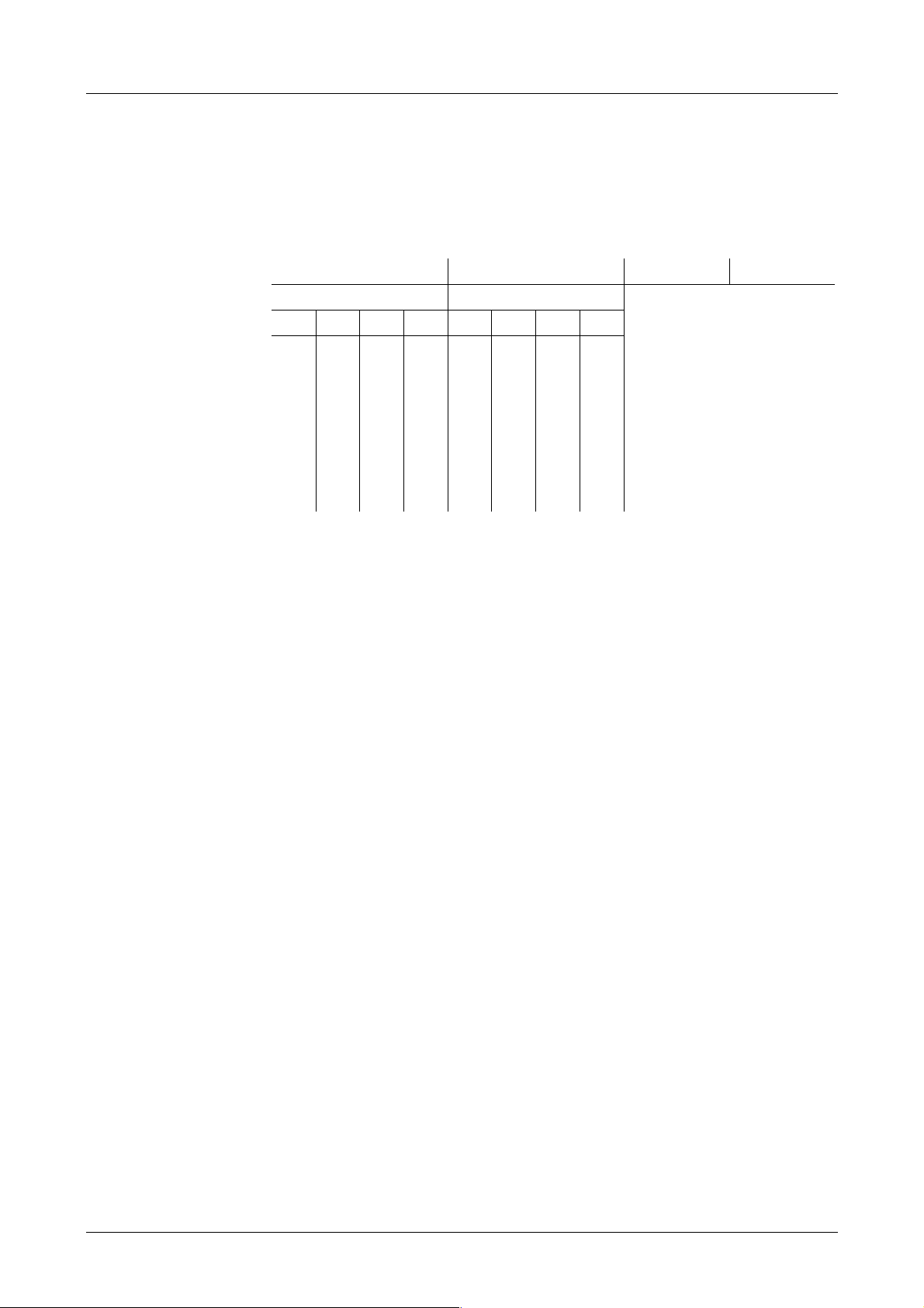
− Software options
The first two hexadecimal digits of the four-digit checksum indicate the software
options installed (i.e. available for use).
st
1
hex. digit 2nd hex. digit 3rd hex digit 4th hex digit
Bit
*)
Bit
*)
no significance
4 3 2 1 4 3 2 1
**)
Speed Angle Board
Diagnostics Plus
Diagnostics Plus
Diesel
Emission Expert Petrol
Emission Expert
—
—
BMW option
*)Bit = 0: Option not available
Bit = 1: Option available
Exception: BMW option
(bit = 0: option available, bit = 1 : option not available)
**)
The Speed Angle Board is absolutely necessary for the software options!
e.g. all options installed
01xx ....... no options installed
− The f ollowing checksums a re also displayed
checksum for sections of the petrol program that are relevant to the
measurement technology
checksum for sections of the diesel program that are relevant to the
measurement technology
checksum for official measurement
supplementary checksum
3. Printer (internal dot matrix or external A4 printer)
4. Keyboard
5. 4 or 5-gas measuring chamber
6. Measuring head for diesel (opacity measuring chamber)
7. Hardware self-test result
3-2 Service Manual

4000 Software
Troubleshooting when hardware self-test fails
The error or status code is represented by a special error code.
Code Problem
1Printer fault
2Keyboard fault
3 Opacity measuring chamber not connected
4 4-gas measuring chamber fault
5 rtc_bat_test
6 Voltage test
7 Fan control unit
8 Pneumatics valve
9 Serial silicon number - motherboard
10 Serial silicon number - opacity measuring chamber
11 Fan opacity measuring chamber 4000
12 Fan opacity measuring chamber 435
17 Communication
18
ü
ý Power supply
19
20
21 Breaker channel
22 TDC channel
23 TDCANA channel
24 Peak meter TDC
25 Peak meter
26 Integrator
27 TDCANA channel filtering
28 TDC sensor, current-fed
29 Stroboscope control
opacity measuring
ï chamber
ü
ï
ï
ï
ï
ï
ï
ï
ý speed angle board
ï
ï
ï
ï
ï
ï
ï
Service Manual 3-3
Software AVL 4000
3.2 Installation of Operating Software (Software update)
The AVL 4000 has an externally accessed slot for memory cards which is compatible with
the PCMCIA PC industry standard. The card has a memory of up to 56 MB.
AVL identification no. EN0339 (4 MB memory)
Basic functions:
− First-time progra mming during production
− Software update during production and service
− Backup medium for customer files
− Data exchange with PC
− Carrier for software options
Installation procedure
Note: Depending on the country specific legislation, this procedure is not supported by
every hardware (France ) or is not allowed (Switzerland).
• Switch the tester off.
• Connect the installation adapter to the 5-pin keyboard port (AVL identification no.
BV2150) an.
• Plug the memory card into the PCMCIA slot.
• Switch the tester on.
The software on the memory card is then installed automatically.
− During installation the installation adapter will output short beeps.
− On completion of the software installation, the tester will output a long beep.
− A continuous sound indicates that the software cannot be installed.
− If the installation fails, you will hear an intermittent signal.
A brief pause between the sounds indicates errored software installation. A long
pause indicates that the customer memory is missing (necessary in Germany and
for the customer memory option).
• Now switch the tester off again.
• Remove the memory card from the PCMCIA slot and disconnect the installation
adapter from the keyboard port.
The installation procedure is now completed. Switch the tester on and check that the new
software is properly installed (Self-test after power-on – software version, checksums).
Instruments destined for Germany must be equipped with
a memory extension!
(See Section 4.2.1.10 Memory Adapter)!
3-4 Service Manual
4000 Evaluation Unit
4. Evaluation Unit
4.1 General Description
Fig. 4-1
The 4000 Evaluation Unit basically consists of the following components:
− housing cover
− rear panel
− front panel
− frame
− LC display
− membra ne keypad
− printer unit
− power supply board
− main boa rd
− speed / angle board
− measuring instruments block
− 4-/5-gas measuring instruments unit
− O
sensor
2
− fan
− rating label
− rubber feet
− memory e x tension (memory adapter)
Service Manual 4-1

Evaluation Unit AVL 4000
4.1.1 Basic Design
The housing consists of a central metal f rame which is d rawn up at the front to the inside
front panel which contains the instruments. Inside the fra me are the power supply unit,
the main board, optional electronics pcbs, speed/angle board, printer adapter,
pneumatics board and chamber adapter.
The display is mounted on the front panel. The front of the housing consists of 2 plastic
cover sections, the display with integrated plexiglass and membrane keypad and the
printer cover. The printer itself is fitted to the inside front panel.
All of the evaluation unit’s connection sockets are on the right-hand side of the housing.
To cater for the various configurations that require different plugs, the side plate is a
cover plate with the relevant socket symbols printed on it.
If the evaluation unit is used as a four-gas (or five-gas) or combination gas tester, the fourgas analyzer with integral power supply unit and the pneumatics rear panel are also
integrated.
The pneumatics rear panel is designed so that the four-gas analyzer sits on a metal
bracket and all the pneumatics elements, such as the condensate trap, particulate filter,
measurement and condensate pump, various filters and non-return valve are
accommodated on the rear panel.
The cover closes the entire housing and has built-in finger grips to make it easier to carry.
The screws are situated in the cover in such a way as to permit the housing to be sealed
for official calibration and subse que nt se aling purposes.
The four-gas tester can be upgraded to a combination tester by connecting a diesel
measuring chamber, installing the necessary electronics pcb and replacing the back panel.
The display is mounted on the outside of the housing and has a plastic cover. The centre
section of the plastic front has the membra ne keypad and an anti-glare, tinted wind ow
through which the LCD display can be seen.
The front panel is suitable for mounting two alternative types of LCD display.
The printer (Epson 5F181) is located on the outside of the housing and (as a dot matrix
printer) sealed in an EMC-quality housing. The paper is fed from above and printed on
the back.
The pcbs are arranged one ab ove the other in the right-hand par t of the housing para llel
to the tester base in the following order:
− main boa rd
− speed/angle board
− option board (free slot)
− The chamber adapter board (for the AVL DiCom 4000) is located on the main
board at slots J4, J6, J10 and J14.
− The printer board is also on the main board at slots J27 and J28.
− The pneumatics board is fixed to the rear panel.
4-2 Service Manual

4000 Evaluation Unit
4.1.2 Evaluation Unit
The evaluation unit hardware consists of:
− the user interface with displays, softkeys, remote control (optional), memory card
connection, strip printer (optional)
− electronic circuits with main board and the option pcbs, printer board, opacity
board, speed/angle board including interfaces and sensor connections.
− free slot for future expansions and the
− power supply assembly with mains switch components, power supply unit, fan
and wiring.
Service Manual 4-3

Evaluation Unit AVL 4000
4.1.3 Pneumatics Rear Panel / 4-/5-Gas Measuring Instruments Unit (5-Gas Option)
The entire pneumatic unit is mounted on the rear wall. The 4-gas measuring instruments
unit is screwed to the rear panel.
probe
The condensate trap, particulate filter, O
mounted directly on the outside of the rear panel.
Condensate trap
Particulate filterConnection for
Control cable connect.
(to opacity measuring
chamber type A only)
Pump
(NO- 5-gas option) sensor and pump are
2
Zero gas
inlet
(pure air)
Activated carbon filter
O
sensor
2
NO sensor (option)
Condensate filter
Inlet for
calibration gas
Heating cable connection
(opacity measuring chamber type A)
or control cable connection
(opacity measuring chamber type 4000)
Fig. 4-2
4-4 Service Manual
Power supply
for pump
Non-return
valve
Analog output
(analog signal of exhaust opacity;
0…5 V
Mains connection
with ON/OFF switch
and fuse box
Condensate
outlet
0…100 % opacity)
=

4000 Evaluation Unit
4.2 Hardware Setup
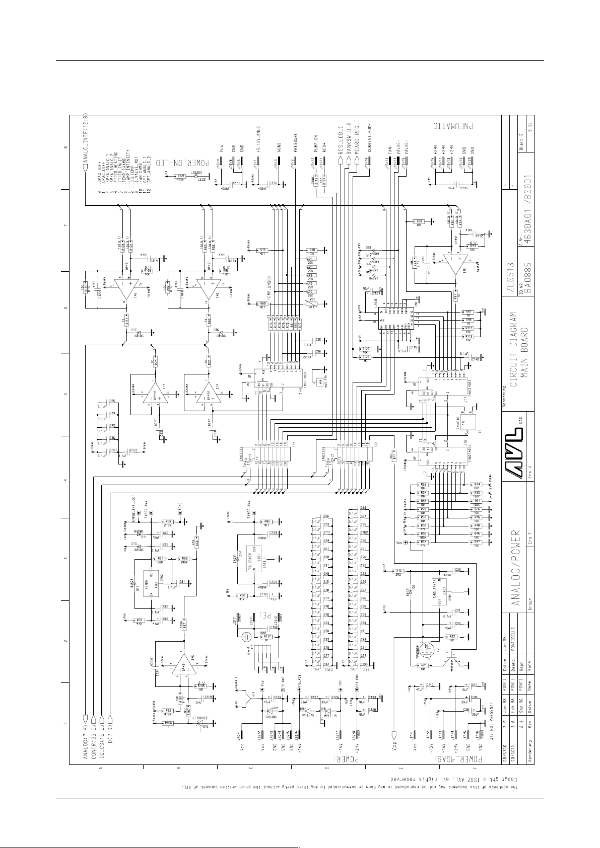
4.2.1 Main Board
The main board represents the heart of the electronics and uses predominantly SMD
technology. The most important function blocks are described below.
4.2.1.1 Digital System
The digital system is built around the highly integrated Intel I80C196NT controller with
20 MHz clock frequency.
The program memory is a flash eprom with 0.5 MB (16 bit bus, 0 wait states, several
independent program and parameter blocks) and can therefore be reprogrammed in the
field.
Two static RAMs are used to store data with a total of 256 KB (16 bit access, 0 wait states).
A further 256 K area of the address space is used as a page area for the internal expansion
memory (on a module receptacle) a nd the e xter nal me mory ca rd. The slot f or the memory
card is welded to the main board.
The address coding is by programmable logic.
The RTC (real-time clock) has a ten-year function guarantee on the lithium cell.
The main board (and therefore the evaluation unit) is unambiguously identified by a
silicone serial number which carries an individual 48-bit code. The internal temperature
of the instrument is monitored by an NTC.
4.2.1.2 Analogue Data Acquisition
The necessary analogue values are measured by the 10-bit ADC installed in the 196NT.
The values measured are the opacity signal, various temperatures, analogue channels
from the speed/angle board and from the free slot and various values for self-diagnostic
purposes (supply voltages, valve motor current). Where necessary, the data is reprocessed
digitally (in particular linearisation, demodulation, digital filtering). This allows, for
example, the filter parameters for the opacity signal to be adjusted to the various
directives.
4.2.1.3 Remote Control Receiver
An integrated receiver/pre-amplif ier is conne cted to the ma in boa rd by a short ca ble. The
output signals are conditioned by the 196NT via an EPA channel.
Service Manual 4-5

Evaluation Unit AVL 4000
4.2.1.4 Interfaces
All external interfaces a re c onne c t e d directly to the pcbs.
The connection for an external PC ke yboard is a standard five-pin plug and is processed
by the 196NT via the timer EPA channels.
An A4 printer can be connecte d by a 25-pin SU B-MIN-D socket as a standard Centronics
parallel interface.
A TRUART module serves the interna l serial interfa ce to the 4- gas measuring instruments
unit in the AVL DiGas and AVL DiCom.
The interface to a host computer (PC, SilverDat computer, Bilanmatik, test bed
computer,…) is also via a standard 9-pin SUB-MIN-D socket and implemented by the
asynchronous serial interface installed in the 196NT. This allows maximum flexibility for
various requirements (such as baud rate, parity check).
Interface socket 9-pin D-sub socket
Interface RS232 serial
Data transfer format 8 bit, 1 stop bit, no parity
Data transfer rate 9600 bit/s
Transfer code ASCII
Pin assignment 1
Provided the instrument has the requisite software installed, measurement data can be
transmitted via this interface to a computer (Isotec interface). The data is transferred a s
ASCII code.
The interface can be set in the service menu under User data/Configuration.
Parameters: 9600 baud, 8 data bits, 1 stop bit, no parity
3…no. of repeats on transfer (= max. 2 repeats)
2 sec. timeout for RS232 (applies to each repeat)
The following operating modes can be selected:
PRG
TxD
2
RxD
3
DTR
4
GND
5
6
DSR
7
RTS
8
CTS
9
RI
Connected to GND
Transmit data (output)
Receive data (input)
Not used
Ground
Not used
− MASTER
The instrument transmits a defined data block to the computer at the touch of a
button or after an event. The computer must be ready to receive the data.
4-6 Service Manual
4000 Evaluation Unit
− SLAVE (Isotec mode)
The computer periodically sends a query to the instrument. If the instrument is
not ready for data transfer, NAK is transmitted to the computer. If measurement
data is available, a data block is transmitted to the computer.
− NO (interface not activated)
Serial interface cable:
Pin assignment pin assignment
AVL 4000 PC
(9-pin SubD) (9-pin SubD)
TxD
2
3
5
2
RxD
3
GND
5
4
6
Bridge 4-6-8
8
Fig. 4-3
4.2.1.5 Display Control and Softkey Connection
The display is operated by means of the SED 1335 LCD Controller with 32 to 128 KB of
display RAM.
In addition, the contrast voltage and the supply voltage for the CCFL background
illumination is generated by an inverter module on the main board. The contrast voltage
can be fine-tuned via an EPA channel of the 196 NT and temperature-compensated by
display-dependent characteristic curves.
The connection cables of the various displays are coded for ease of identification.
The 8 keys (softkeys and permanent keys) are addressed by ESD-protected drivers.
4.2.1.6 Generation of Auxiliary Voltage
Various voltages are generated from the 4 power supply unit voltages (5 V, ±15 V, 24 V):
± 15 V analogue filtered voltages for powering the analogue circuits
Vpp (+12 V) switchable programming voltage for flash eproms
+ 5.12 V analogue precision reference voltage for ADC channels in the 196NT
- 5 V analogue negative supply for low-cast multiplexer and op amps
4.2.1.7 Board Control
The printer board (optional) and chamber adapter board (for AVL DiCom 4000) are
plugged straight into the main board, whereas the pneumatics board, speed/angle board
and free slot are connected via control or ribbon cables.
The speed/angle board and free slot are served by fast, synchronous, serial interfaces
(SSIO) of the 196NT which means that both intelligent pcbs with their own processors
and non-intelligent boards can be connected via parallel- serial converter I/O mod ules. In
addition, digital synchronisation signals, interruption inputs, analogue channels and
timer channels (EPA ports) are available for both boards.
The various equipment configurations are registered automatically which reduces the
time and cost of programming and set-up.
Service Manual 4-7

Evaluation Unit AVL 4000
4.2.1.8 Printer Board (Option)
If the printer option has been purchased, the printer board is inserted in the main board
at right angles to it (slots J27 and J28). It contains the control circuit for the integral strip
printer (dot matrix printer driver, motor, fast paper feed and evaluation of tachogenerator and home switch).
Because most of the pcb is taken up with power transistors, the boards are manufa ctured
using wired technology.
For installation, see section 4.5.1 Internal Printer Unit.
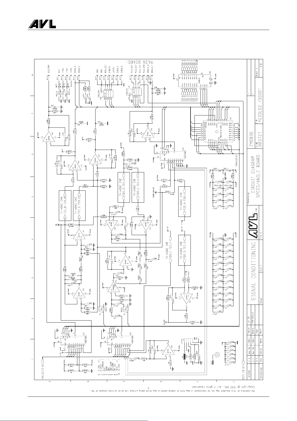
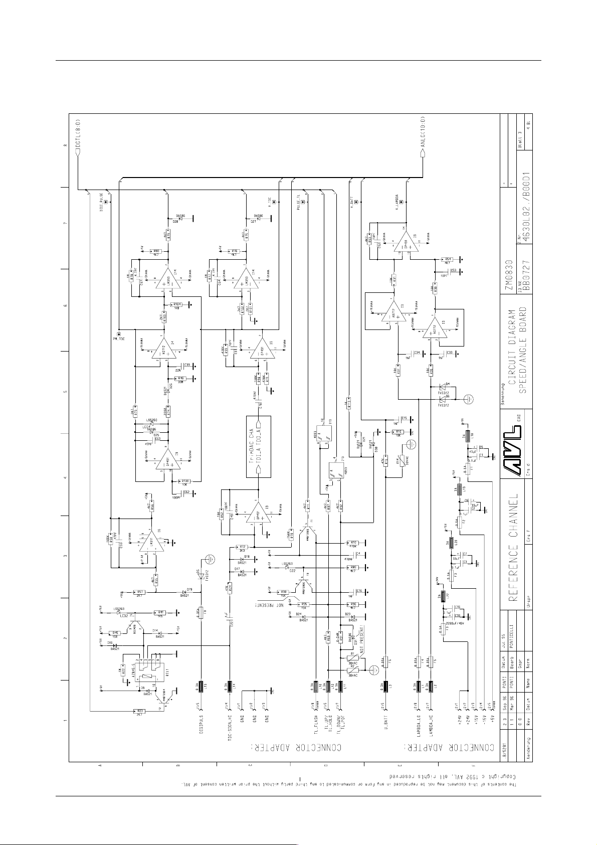
4.2.1.9 Speed / Angle Board with Diagnostics Cable Concept
(Option/Installation)
The speed/angle board is an option that can be used to record speed, angle, oil
temperature, the lambda probe voltage and the voltage of the vehicle electric system. The
speed/angle board is basically non-intelligent, i.e. does not have its own processor. All
speed and angle signals are converted via two processing channels to digital pulses which
are evaluated by the 196NT on the main board.
Measurements:
• RPM measurements
Supported sensors:
− inductive sensors (e.g. T DC sensors) with different timings
(incl. Motronic flywheel)
− optical sensor
− digital pulses from engine management system
− AVL clamp-on transducers (AVL DiGas 4000 and AVL DiCom 4000)
− RIV sensors (AVL DiGas 4000 and AVL DiCom 4000)
− needle movement sensors (AVL DiGas 4000 and AVL DiCom 4000)
− inductive trigger clamp (AVL DiGas 4000 and AVL DiCom 4000)
− AVL DiSpeed 490 (AVL DiGas 4000 and AVL DiCom 4000)
Measurement range 250…6000 rpm (diesel engines)
250…8000 min
Resolution: 10 rpm
Accuracy: ± 2 rpm (rounded to nearest 10 rpm)
• Angle measurement
The start of delivery, sta rt of injection and ignition a ngle are measured by processing
a cylinder 1 sensor signal in conjunction with a reference signal.
-1
(petrol engines)
Supported cylinder 1 sensors:
− AVL clamp-on transducers (AVL DiSmoke 4000 and AVL DiCom 4000)
− RIV sensors (AVL DiSmoke 4000 and AVL DiCom 4000)
− needle movement sensors (AVL DiSmoke 4000 and AVL DiCom 4000)
− inductive trigger clamps (AVL DiGas 4000 and AVL DiCom 4000)
(Customer-specific) special signals can be conditioned with an external black box as an
option.
4-8 Service Manual

4000 Evaluation Unit
Supported reference sensors:
− inductive sensors (TDC sensors) with var ious timings
(incl. Motronic flywheel)
− optical sensors
− digital pulses from engine management system
− strobe with engine marks
Measurement range: 0…59.9° CA (strobe mode)
-9.9…99.9° CA (other reference sensor)
Resolution: 0.1° CA
Accuracy: 1.0° CA (strobe mode)
0.5° CA (other reference sensor)
• Measurement of dwell angle in petrol engines
Interrupter signal (ignition primary) (AVL DiGas 4000 and AVL DiCom 4000)
Measurement range: 0.0…99.9%
Resolution: 0.1%
Accuracy: 1.0%
• Oil temperature measurement
The temperature is measured by inserting the AVL oil temperature sensor, available
in various lengths, into the sump (or more rarely, into the cooling water).
Measurement range: 0…120° C
Resolution: 1 °C
Accuracy: ± 4° C
• Lambda probe voltage and voltage of vehicle electric system:
A voltage can be measured (lambda probe voltage or the voltage of the vehicle
electric system).
Measurement range: 0.00...32.00 V DC
Resolution: 40 mV
Accuracy: 160 mV
Graphical representation (lambda probe voltage only)
Amplitude: 0…1.8 (5.0) V -40 (120) mV resolution
Representation time: 10 (20) sec -20 (40) msec resolution
Frequency evaluation: 0.1…10 Hz -0.01 Hz resolution, ±0.02 Hz
Service Manual 4-9

Evaluation Unit AVL 4000
• Diagnostics cable concept:
There are five plugs to connect the supported sensors:
− clamp-on transducer/RIV plug
− cyl1 plug for needle movement sensor, inductive trigger clamp and interrupter
connection (black box for special signals)
− reference plug for inductive sensors, optical sensor, digital pulses and strobe
(black box for special signals, e.g. universal rpm measurement)
− voltage plug for c onnecting lambda sensor and vehicle electric system
− oil temperature plug
There are short adapter cables for the connection to the engine, which can easily be
accommodated on the instrument trolley. Alter natively, a de dicated connection cable
can be used without an extension lead.
The speed angle board option (ident. number BO1721) consists of the following
components:
− speed angle board
− ribbon cable
Installation
• Switch the instrument off and disconnect from the mains.
• Open the instrument.
• Remove the side housing sections
(undo 4 Phillips screws on the outside; one hexagon nut on the inside).
• Remove the GND connector.
• Insert the speed angle board.
• Reconnect GND connector.
• Connect the speed angle board to the main board using the r ibbon c able / slot J16
(SPEED/ANGLE).
• Mount the speed angle board
(4 Phillips screws on the outside; one hexagon nut on the inside).
• Connect analogue OUT socket (on rear panel) (red lead to AN_OUT and lead to GND
of speed angle board).
• Enter the speed angle board option on the option sticker.
• Reassemble the instrument.
• Connect the mains cable and switch the instrument on.
4-10 Service Manual

4000 Evaluation Unit
4.2.1.10 Memory Adapter
The Memory Adapter (AVL identification no. BB0730) is installed on the main board.
• Insert the Memory Adapter at slots J8 and J9 on the main board
• Mark the memory adapter option on the options stic ke r.
4.2.1.11 Chamber Adapter (AVL DiCom 4000)
The Chamber Adapter is needed to operate the opacity measuring chamber.
4.2.1.12 Extension Slot
There is a free extension card slot for future upgrading as the result of product
development. An option installed in this slot is located above the Speed/Angle Board.
If an extension card is installed, the side panel of the housing has to be changed.
4.2.1.13 Mains Switch Assembly
The mains switch assembly consists of the mains ca ble connection as an inlet connector
for non-heating appliances, the power switch, externally accessed mains f use and a filter
required by the statutory provisions for mains pollution.
4.2.1.14 Converting 230 V to 115 V Device
• Replace 230 V pump (on the real panel) with 115 V pump
The hose lengths must not be changed!
• Both fuses in the mains switch group must be replaced by 3.15 A slow-blow fuses.
• The modification from 230 V to 115 V must be indicated clearly on the rating plate
(with a warning on a sticker)
The power supply unit can continue to be used without any modif ic ations.
4.2.1.15 Power Supply Unit
All members of the instrument family contain the same purchasable power supply unit.
Technical data
− Computer Products NFS80-7606
− long-range input 90…260V AC, 125…360V DC
− outputs (short-circuit-proof):
+5V / 8A (±2%, ripple 1%) for digital part
+15V / 2.5A (±3%, ripple 1%) mainly analogue supply
-15V /2.5A (±3%, ripple 1%) mainly analogue supply
+24V / 2A (+10/-5%, ripple 1%) power (heating, fan, solenoid valve,
strobe,…)
− Output: 80 W (110 W with forced cooling)
− UL, CSA, VDE, IEC1010, IEC 950 approved
− mains pollution under VDE limit B
Service Manual 4-11

Evaluation Unit AVL 4000
4.2.1.16 Fan
The machine is ventilated at the sides and also at the rear to keep the pneumatic pump
cool. The angle of the air flow near the display has been kept as small as possible to
prevent the screen from becoming dirty too quickly.
The fan speed depends on the temperature.
4.3 Dismantling the 4-/5-Gas Measuring Instruments Unit
• Disconnect the plug from the mains!
• Open the housing cover (3 screws on the sides of the evaluation unit). Push the cover
towards the back until it is released from the mounting clamps.
• Disconnect all cables from the main board, power supply unit and ignition board to
the rear panel.
• Remove the 4 fixing screws on the rear panel.
• Remove the 3 fixing screws on the base plate.
• Remove the solenoid valve from the rear panel.
• Disconnect the hoses to the pneumatics module.
• Remove the rear panel pulling towards the back. Remove the activated carbon filter
from the rear panel.
• Disconnect the mains wiring to the power supply unit of the measuring instruments
unit.
• Carefully lift the measuring instruments unit upwards.
• The measuring instruments unit can now be completely removed.
For a technical description of the measuring instruments unit, see section 5 4-/5-Gas
Measuring Instruments Unit.
4.4 Housing
Components
− Cover
− Lower shell
− Front panel, complete (including keypad and display)
− Front panel (without ele c tronic c ompone nts)
− Rear panel, complete
− Rear panel (with no devices)
− 4 rubber feet
4-12 Service Manual

4000 Evaluation Unit
4.5 Printer
A hardcopy can be printed out of all the measurement results displayed. The official
measurements end with an official results printout.
4.5.1 Internal Printer Unit (Option/Installation)
It takes about 30 seconds to printout a hardcopy. A results printout takes ½ to 1 minute
depending on how long it is. During this time, none of the instrument’s f unctions can be
activated.
Technical data:
− Seiko Epson, model M-181
− 6-nee dle miniature printer for normal paper
− max. 30 chars per line (5 × 7 matrix)
− average speed 1.3 lines/sec
− 180 pixels per pixel line in graphics mode
− carbon copy possible
− paper width approx. 57.5 mm
− typical service life > 1 million characters
− typical service life of long-life ribbon 1 million characters (violet), 600 000
characters (black)
The printer option (ident. number BO1720) consists of the following components:
− printer adapter BB0279
− printer cable (for printers with connection cable) BV1983
− paper shaft YM3388
− paper roll for dot matrix printer HP0057
− 3 metal screws DS1101
Instructions for conversion
• Switch off the instrument and disconnect the mains plug.
• Open the instrument completely.
• Insert the printer adapter onto the main board (slots J27 and J28).
• Remove the plastic cover at the front of the instrument
• Pull the fixing shaft out of the printer‘s plastic cover.
• Connect the connection cable to the printer adapter.
• Fasten printer in position with the 3 metal screws.
• Enter the printer option on the options sticker.
• Reassemble the instrument.
• Plug the mains cable back in and switch on again.
• Insert the paper roll and push the paper through.
Service Manual 4-13

Evaluation Unit AVL 4000
4.5.2 External A4 Printer (Option)
An external A4 printer can be connected via a sta ndard Centronics interface. When an
external printer is on-line, all outputs (hardcopy, results printout) are diverted to that
printer. The time required for printing depends very much on the printer’s buffer.
A standard Centronics cable is used for the printer (AVL identification no. EX0308).
4.6 LCD
The 320 × 240 display is controlled by a separate controller.
The display contrast can be adjusted in the Service menu.
4.7 Membrane Keypad
The integral membrane keypad contains the 6 softkeys and 2 permanent keys. The
softkeys are used by the operator to control the progra m run or me nu selections.
Rarely needed data (e.g. garage address, vehicle data etc.) can be input using the editor
which is also implemented by the softkeys. If more frequent input is required (e.g. data
input for country-specific variants), the external PC keyboard option should be used.
The software supports an external PC keyboard (connected to the 5-pin standard PC
keyboard interface). Function keys F1 to F6 have a parallel function with the softkeys.
When the instrument is powered up, the external keyboard is initialised during the selftest.
In the Service menu (User data/Languages) it is possible (depending on the software
version) to select the keyboard layout after selecting the language for the menu
prompting.
If a different keyboard layout is selected, the instrument is re-started and the keyboard reinitialised during the self-test. After the re-start, the instrument is immediately ready for
measurements – you do not have to wait for the 4-/5-gas measuring instruments unit to
warm up.
4.8 Fan
The axial fan is screwed onto the rea r panel with 4 M4×25 cheese-head screws.
The instrument is ventilated at the bottom and also at the rear to keep the pneumatic
pump cool. The angle of the air flow near the display has been kept as small as possible to
prevent the screen from becoming dirty too quickly.
The fan speed depends on the temperature.
4-14 Service Manual

4000 Evaluation Unit
4.9 Main Board
4.9.1 Components Location Diagram
Service Manual 4-15

Evaluation Unit AVL 4000
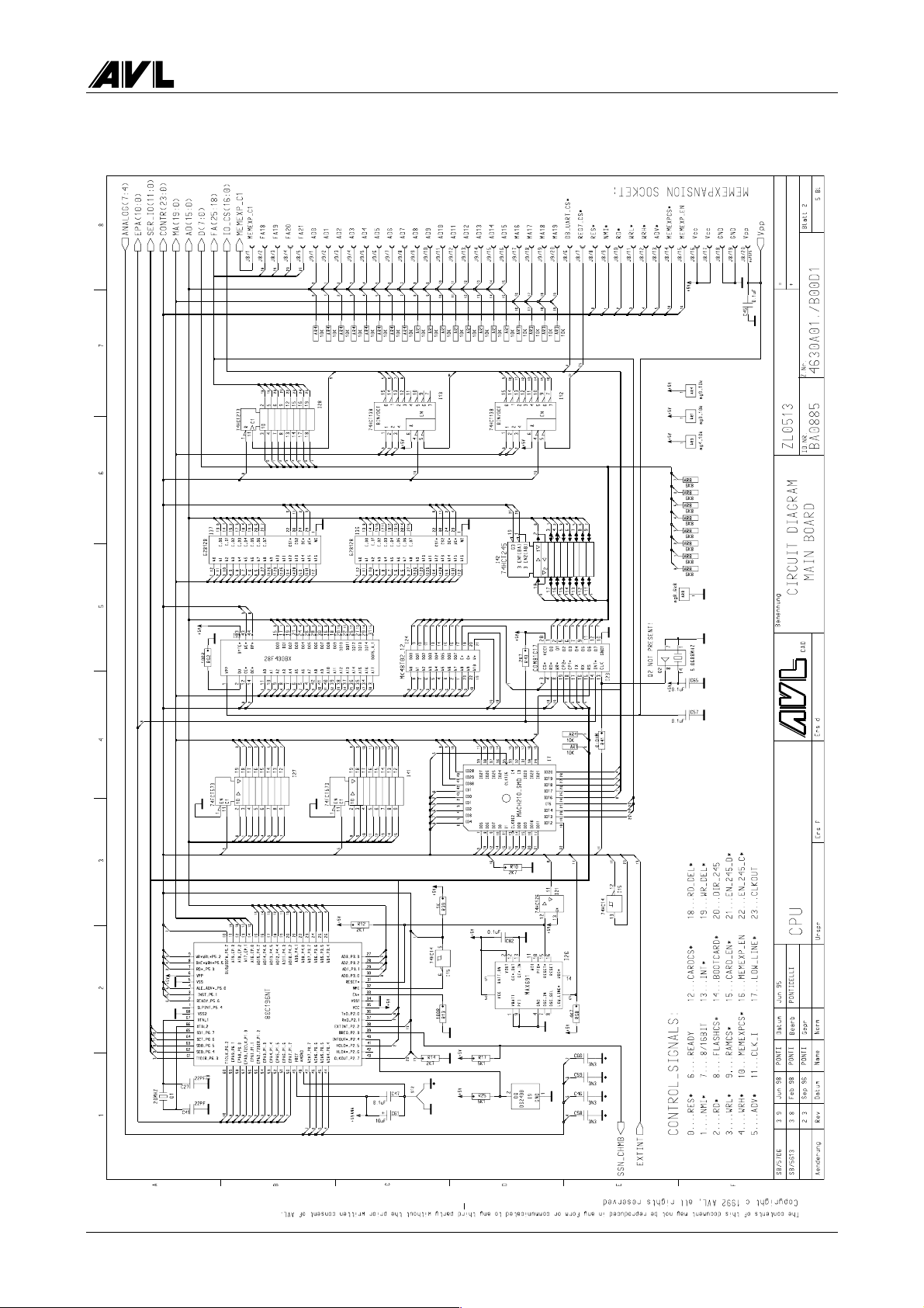
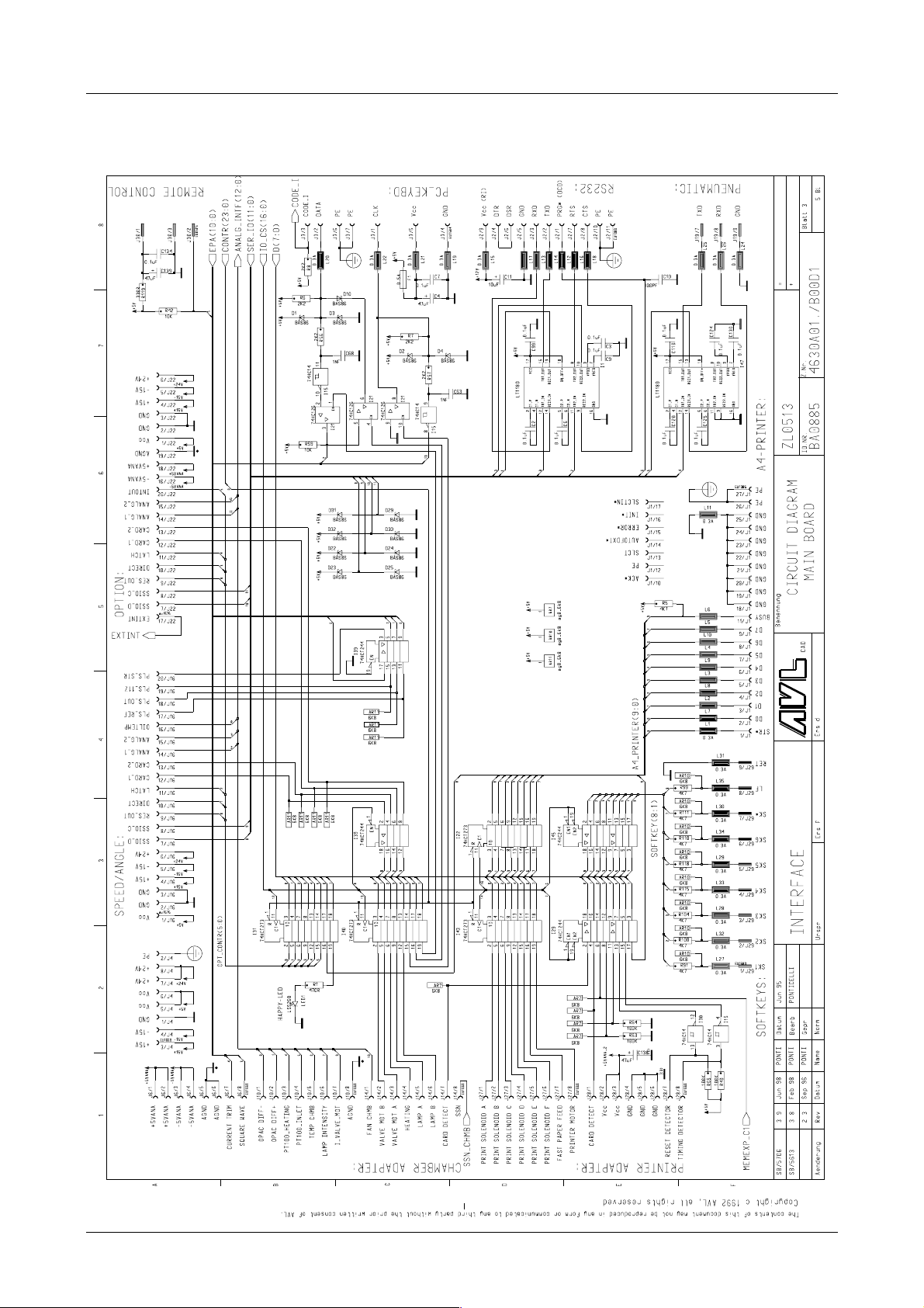
4.9.2 Circuit Diagrams
4-16 Service Manual
4000 Evaluation Unit
Service Manual 4-17
Evaluation Unit AVL 4000
4-18 Service Manual

4000 Evaluation Unit
Service Manual 4-19
Evaluation Unit AVL 4000
4-20 Service Manual

4000 Evaluation Unit
4.10 Speed Angle Board
4.10.1 Components Location Diagram
Service Manual 4-21

Evaluation Unit AVL 4000
4.10.2 Circuit Diagrams
4-22 Service Manual
4000 Evaluation Unit
Service Manual 4-23
Evaluation Unit AVL 4000
4-24 Service Manual

4000 Evaluation Unit
Service Manual 4-25

Evaluation Unit AVL 4000
4.11 Pneumatics Board
4.11.1 Components Location Diagram
4-26 Service Manual

4000 Evaluation Unit
4.11.2 Circuit Diagram
Service Manual 4-27

Evaluation Unit AVL 4000
4.12 Printer Adapter
4.12.1 Components Location Diagram
4-28 Service Manual

4000 Evaluation Unit
4.12.2 Circuit Diagram
Service Manual 4-29

Evaluation Unit AVL 4000
4.13 Memory Adapter
4.13.1 Components Location Diagram
4-30 Service Manual

4000 Evaluation Unit
4.13.2 Circuit Diagram
Service Manual 4-31
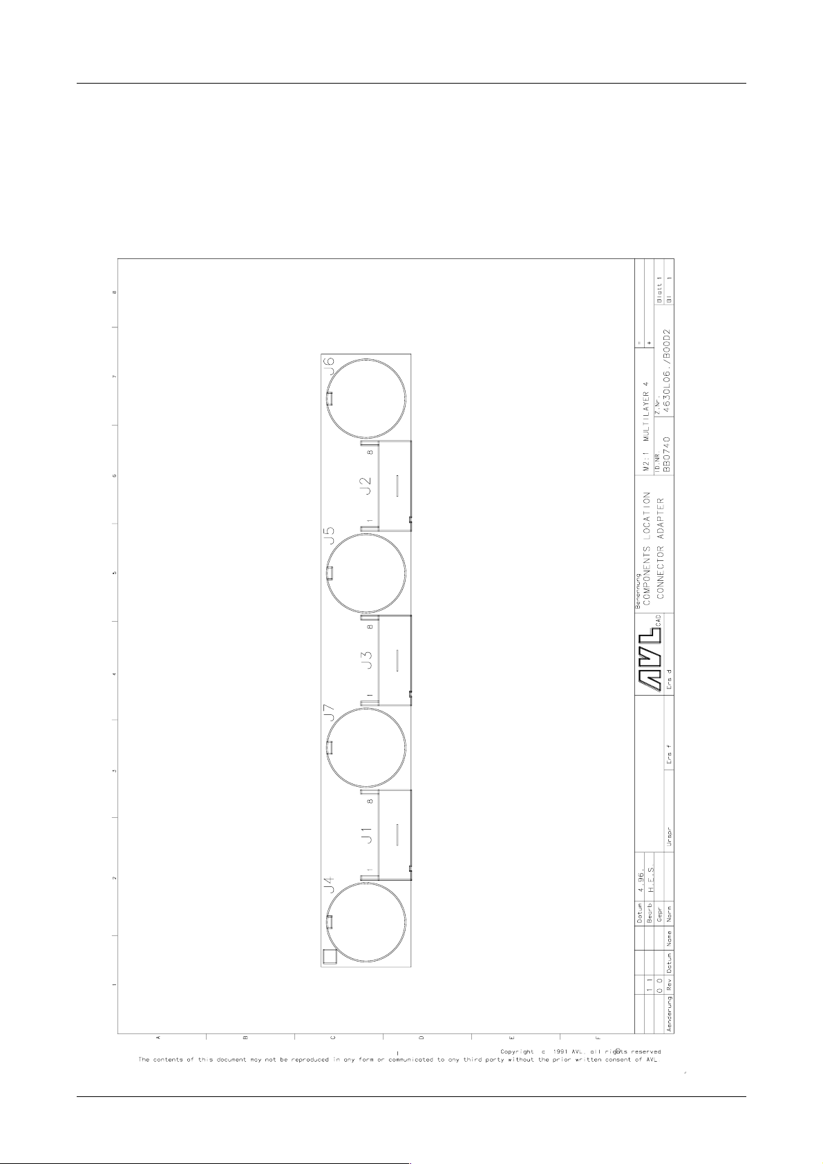
Evaluation Unit AVL 4000
4.14 Connector Adapter
4.14.1 Components Location Diagram
4-32 Service Manual

4000 Evaluation Unit
4.14.2 Circuit Diagram
Service Manual 4-33
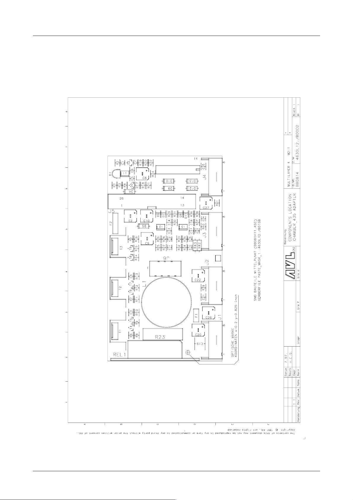
Evaluation Unit AVL 4000
4.15 Chamber Adapter (opacity measuring chamber type A)
4.15.1 Components Location Diagram
4-34 Service Manual
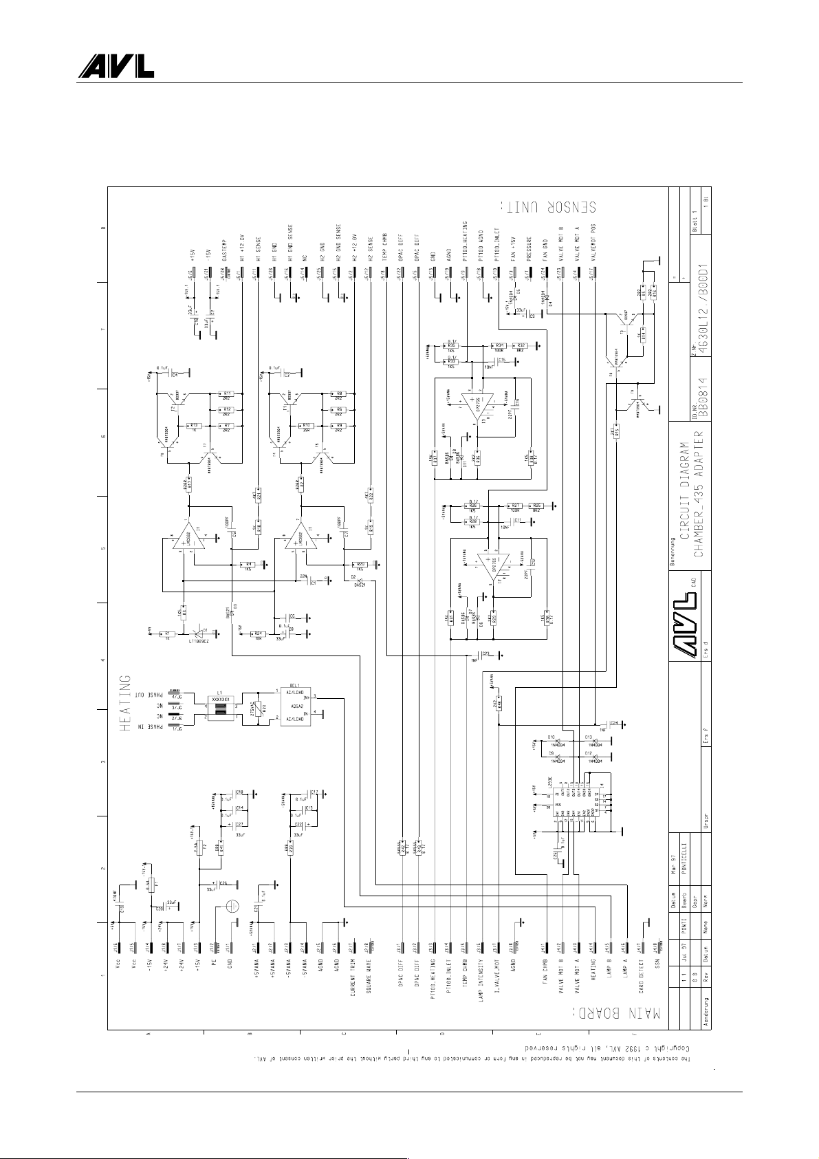
4000 Evaluation Unit
4.15.2 Circuit Diagram
Service Manual 4-35
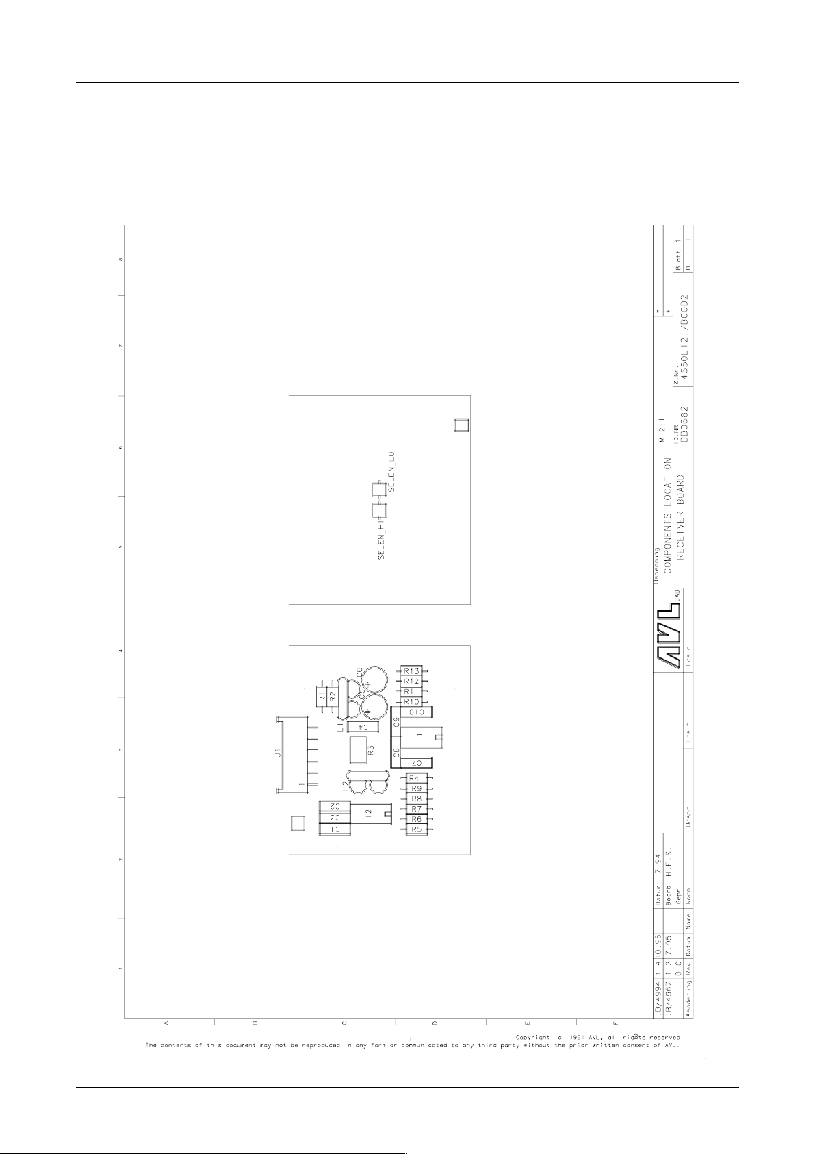
Evaluation Unit AVL 4000
4.16 Receiver Board (opacity measuring chamber type A)
4.16.1 Components Location Diagram
4-36 Service Manual

4000 Evaluation Unit
4.16.2 Circuit Diagram
Service Manual 4-37
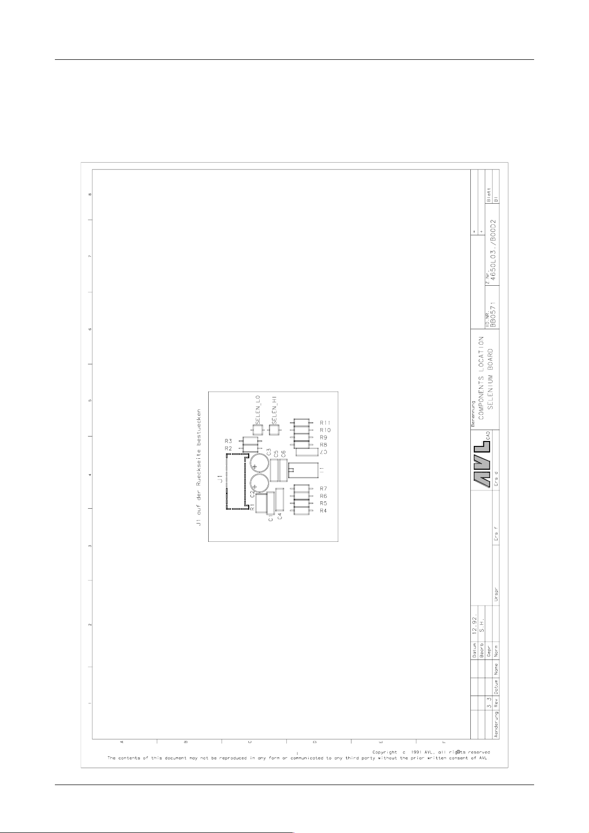
Evaluation Unit AVL 4000
4.17 Selenium Board (opacity measuring chamber type A)
4.17.1 Components Location Diagram
4-38 Service Manual
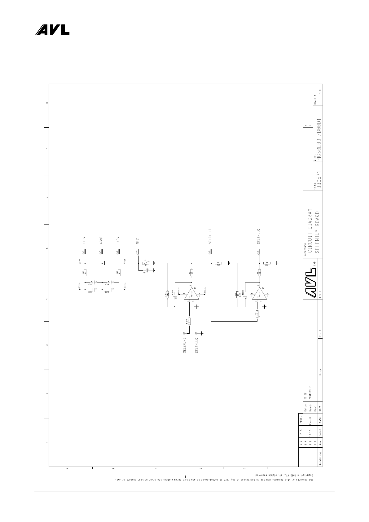
4000 Evaluation Unit
4.17.2 Circuit Diagram
Service Manual 4-39

Evaluation Unit AVL 4000
4.18 Chamber Adapter (opacity measuring chamber 4000)
4.18.1 Components Location Diagram
4-40 Service Manual

4000 Evaluation Unit
4.18.2 Circuit Diagram
Service Manual 4-41

Evaluation Unit AVL 4000
4.19 Transmitter Board (opacity measuring chamber 4000)
4.19.1 Components Location Diagram
4-42 Service Manual

4000 Evaluation Unit
4.19.2 Circuit Diagram
Service Manual 4-43

Evaluation Unit AVL 4000
4.20 Receiver Board (opacity measuring chamber 4000)
4.20.1 Components Location Diagram
4-44 Service Manual

4000 Evaluation Unit
4.20.2 Circuit Diagram
Service Manual 4-45

Evaluation Unit AVL 4000
4.21 Fan Board (opacity measuring chamber 4000)
4.21.1 Components Location Diagram
4-46 Service Manual

4000 Evaluation Unit
4.21.2 Circuit Diagram
Service Manual 4-47

Evaluation Unit AVL 4000
4.22 Wiring Diagrams
A
B
C
D
E
F
G
Bl.
1
2
Blatt
J2
123456789
POWER SUPPLY
+5V
+5V
+5V
GND
GND
GND
VCC(+5V)
VCC(+5V)
1
2345678
J26
MAIN BOARD
HOSIDEN
DISPLAY
78910 11
FRONT PANEL
101112
JD
123
4
13
5
FAN
CAL
VALVE
BACK
VALVE
123456789
P3
123
(ID-NR)
(Ers.d.)(Ers.f.)(Urspr.)
REAR PANEL
ANDROS MEAS. INSTR.
TXD
RXD
GND
N.C.
TXD
RXD
123
N.C.
=BV1989=
N.C.
GND
4
=BV1987=
=EX0470=
3PE1
J7
PE
VALVE-
VALVE+(+24V)
VALVE+(+24V)
2
4
3
FAN-
FAN+(+24V)
1
J5
VALVE-
VALVE+(+24V)
1
2
2
J6
GND
GND
GND
+15V
+15V
-15V RETURN
-15V
N.C.
+24V
=BV1981=
-15V
GND
+15V
+24V
J4
PNEUMATIK BOARD
DISPLAY
TOSHIBA
CFFL
REMOTE
123
ANDROS PIGGYBACK
GND
O2 OUT
O2 OUT
1
O2 SENSOR
DIG GND
+5V
GND SENSE
+15 SENSE
+15V
+15V ANLG
GND ANLG
-15V ANLGJAGND
=BV1994=
PE
VALVE-
5
6
+5V
+15V
DIG GND
+15 SENSE
GND SENSE
GND ANLG
+15V ANLG
123456789
-15V ANLG
P2
ANDROS POWER SUPPLY
J1
3456789
1
2
101112
13141516171819
WIRING - SIGNAL
GND ANLG
GND ANLG
=BV2009=
N.C.
4530.00./B00C2
BEARBEITUNG
(Teil)
(Z.Nr.)
(Ben.)
08.98 GUTSCHI
Datum Name
Gepr
Norm
Bearb
GND ANLG
2
3
.B 02
Änderung REV Datum Name
Anz
Buchst
20
PNEUMATIC BOARD
FAN-
VALVE-
VALVE-
+24V
+24V
+24V
GND
GND
+5.12V ANLG
PRESSURE
AGND
VCC
GND
GND
TXD
RXD
GND
CURRENT PUMP
RES*
+5V
REMOTE OUT
PUMP ON
=BV1988=
GND
LP
PE
YD
WF
XD0
XD1
XD2
XD3
XD0
XD1
XD2
GND
XSCL
VCC(+5V)
DISPL OFF*
12345678910111213
Vadj
Vee(-24V)
14
J18
J1
MAIN BOARD 4630A01
123456789
STR*D0D1D2D3D4D5D6D7
23456
SIDE PANEL
1
101112131415161718192021222324
ACK*
BUSYPESLCT
AUTOFDXT*
ERROR*
XD3
DISPL OFF*
12345678910111213
J15
INIT*
SLCTIN*
GND
GND
GND
GND
PRINTER A4
A
B
C
LP
YD
N.C.
GND
GND
GND
XSCL
VCC(+5V)
252627
GNDPEPE
GND
PE
Vadj
Vee(-24V)
14
J11
J2
123456789
PRG
TXD
RXD
RS232
D
VAC N
1
DTR
VAC PH
4
GND
DSR
+5V
GND
REMOTE IN
1
2
J30
RTS
CTS
VCC(+12V)PEPE
+5.12V ANLG
3
1
J19
J3
12345
10
11
CLK
DATA
PC KEYBOARD
E
AGND
PRESSURE
2
3
CODE I
GND
F
GND
VCC(+5V)
4
6
VCC(+5V)PEPE
GND
675
TXD
7
RXD
8
GND
CURRENT PUMP
9
101112
J29
FRONT PANEL
SOFTKEYS
FAN-
+24V
RES*
VALVE-
VALVE-
PUMP ON
13141516171819
5
1234678
SK1
SK2
SK3
SK4
SK5
SK6
G
+24V
+24V
SK*LFRETURN
GND
GND
20
9
1 234567
OTHER PURPOSE WITHOUT THE PRIOR WRITTEN PERMISSION OF AVL LIST GMBH.
AVAILABLE TO AN Y THIRD PARTY OR USED FOR MAN UFACTURING O R ANY
REPRODUCED IN ANY FORM, EITHER IN WHOLE OR IN PART, OR MADE
THIS DRAWING IS THE PROPERTY OF AVL LIST GMBH AND MAY NOT BE
COPYRIGHT 199 4 AVL LIST GMBH, ALL RIGHTS RE SE RVED
c
H
4-48 Service Manual
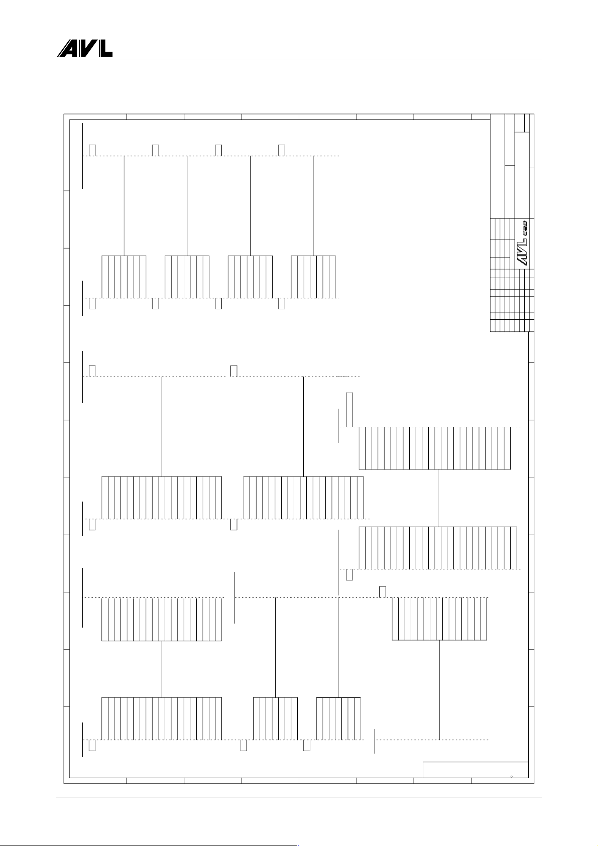
4000 Evaluation Unit
A
PE
GND
+15V
123
J4 J1
MAIN BOARD CHAMBER 435 ADAPTE R
J2
78910 11
MEMORY ADAPTER
-15V
Vcc(+5V)
456
B
C
J3
D
E
J4
F
G
Bl.
1
1
Blatt
(ID-NR)
(Ers.d.)(Ers.f.)(Ursp r.)
WIRING - OPTIONS
4530.00./B00C2
BEARBEITUNG
(Teil)
(Ben.)
(Z.Nr.)
GUTSCHI
01.98
Datum Name
Gepr
+24V
+24V
Vcc(+5V)
8
7
J6 J2
AGND
+5VANA
+5VANA
+5VANA
+5VANA
1234567
AGND
OPAC DIFF-
OPAC DIFF+
SQUARE WAVE
CURRENT TRIM
8
PT100 HEAT
1234567
J10
AGND
I VALVE MOT
8
FAN CHMB
VALVE MOT B
VALVE MOT A
1234567
TEMP CHMB
LAMP INTEN
PT100 INLET
J14
SSN
LAMP A
LAMP B
HEATING
CARD DETECT
8
J1
Norm
Bearb
.B/ 02
Änderung REV Datum Name
Anz
Buchst
7
FA18
MEMEXP C1
123
FA19
FA20
FA21
456
RD*
NMI*
RES*
REG7 CS*
DB UART CS*
8910
7
ADV*
WRL*
WRH*
MEMEXP EN
MEMEXPCS*
111213141516171819
VCC
VCC
VPP
GND
GND
20
J8
MAIN BOARD
123456789
VCC
GND
GND
+15V
-15V
23456
VCC
-15V
GND
GND
+15V
1
123456789
J16
1011121314151617181920
+24V
SSIO D
SSIO C
RES OUT
DIRECT
LATCH
=BV1984=
+24V
SSIO D
SSIO C
DIRECT
RES OUT
10
LATCH
111213141516171819
CARD 1
CARD 2
ANALG 2
ANALG 1
OILTEMP
PLS REF
PLS OUT
PLS 11%
PLS STR
CARD 1
CARD 2
PLS REF
PLS 11%
ANALG 1
ANALG 2
PLS STR
PLS OUT
OILTEMP
20
MAIN BOARD SPEED ANGLE BO AR D
A
B
C
AD0
123
J9
PRINTER ADAPTE R
J27
AD3
AD4
AD5
AD1
AD2
456
SOLENID A
SOLENID B
SOLENID C
SOLENID D
1234567
D
SOLENID E
AD6
7
AD7
8910
SOLENID F
PAPER FEED
AD8
MOTOR
8
BACK PANEL
AD9
AD10
AD11
AD12
AD13
AD14
AD15
111213141516171819
CHAMBER 435 ADAPT ER
VCC
VCC
GND
CARD DETECT
1234567
J28
E
MA16
GND
GND
CONTROL UNIT
2345678
H1 +12V1H2 SENSE
MA17
MA18
MA19
20
H1 +12V
H2 +12V
123
J5
RESET
TIMING
8
FAN 12V
VALVEMOT A
SELEN HI
+12V
+15V
FAN +15V
OPAC DIFF
VALVE MOT A
456
J3
123456789
TIMING
PRINTER
F
9
10111213141516171819202122
PRESSURE
NTC CHMB
PT100 CHMB
PT100 INLET
H1 SENSE
H2 SENSE
SHIELD
H1 GND
H2 GND
=BV2122=
NC
GND
PT 100 IN
H1 SENSE
PRESSURE
7
H2 DENSE
TEMP CHMB
PT 100 HEAT
111213141516171819
8910
H2 GND SENS
10111213141516
TIMING
SOLNID A
COMMON
SOLENID F
SOLENID E
SOLENID D
SOLENID C
SOLENID B
MOTOR-
=BV1983=
G
FAN GND
H1 GND SENS
MOTOR+
VALVEMOT B
VALVEMO POS
RESET
SELEN LO
PT 100 AGND
RESET
-12V
GASTEMP
AGND
AGND
20
FPF TRIGGER
FPF TRIGGER
23
24
AGND
PT100 AGND
VALVEMOT PO
H1 GND SENS
+15V
FAN GND
OPAC DIFF
VALVE MOT B
2122232425
N.C.
H
25
H2 GND SENS
H2 GND
H1 GND
26
1 23456
OTHER PURPOSE WITHOUT THE PRIOR WRITTEN PERMISSION OF AV L LIST GMBH.
AVAILABLE TO ANY THIRD PARTY OR USED FOR MANUFACTURING OR ANY
REPRODUCED IN ANY FORM, EITHER IN WHOLE OR IN PART, OR MADE
THIS DRAWING IS THE PROPERTY OF AVL LIST GMBH AND MAY N OT BE
COPYRIGHT 1994 AVL LIST GMBH, ALL RIGHTS RESERVED
c
Service Manual 4-49

Evaluation Unit AVL 4000
A
8
MEAS. INSTR. SUPPORT
COVER
REAR PANEL
SIDE PANEL
DISPLAY SUPPORT
7
L=300MM
L=600MM
L=300MM
L=300MM
L=600MM
56
B
NOx COVER
L=600MM
CENTRAL GROUND
C
Buchse
123
3P UNML
J6
CHAMBER 435 ADAPTER
123
D
Bl.
1
1
Blatt
(ID-NR)
(Ers.d.)(Ers.f.)(Urspr.)
4
VERDRAHTUNG NETZ
4530.00./B00D3
BEARBEITUNG
PHASE IN
N.C.
N.C.
braun
HEATING
GND
NULL
PE21
PHASE OUT
(Ben.)
(Teil)
Datum Name
(Z.Nr.)
01.98 GUTSCHI
Gepr
Norm
Bearb
PHASE
.C/ 02
Änderung REV Datum Name
Anz
Buchst
ERDE
NULL
PHASE
=BV2123=
GND
NULL
PHASE
123
3P UNML
Option Sensor Unit 4350
PLUG
BACK PANEL
4
J1
12345
POWER SUPPLY
GND
N.C.
NULL
N.C.
PHASE
SOCKET
123
3P UNMNL
GND
=BV1979=
GND
NULL
PHASE
PNE
BACK PANEL
MAINS
123
A
PLUG
123
NULL
PHASE
GND
NULL
PHASE
=BV1985=
N.C.
N.C.
NULL
GND
PHASE
12345
P1
ANDROS POWER SUPPLY
B
PNEUMATIC BO ARD
C
GND
12345
J2
PUMPE
PE
N.C.
GND
BACK PANEL
PUMPE-OUT
123
PHASE-IN
PHASE-OUT
PUMPE-IN
123
PE
PHASE-IN
N.C.
GND
PHASE-OUT
=BV1990=
N.C.
N.C.
NULL
PHASE
N.C.
N.C.
GND
N.C.
PHASE-OUT
12345
6PHASE-IN
J3
1234
OTHER PURPOSE WITHOUT THE PRIOR WRITTEN PERMISSION OF AVL LIST GMBH.
AVAILABLE TO ANY THIRD PARTY OR USE D FOR MANUFACTURING OR ANY
REPRODUCED IN ANY FORM, EITHER IN WHOLE OR IN PART, OR MADE
THIS DRAWING IS THE PROPERTY OF AVL LIST GMBH AND MAY NOT BE
COPYRIGHT 1994 AVL LIS T GMBH, ALL RIGHTS RESERVE D
c
D
E
4-50 Service Manual

4000 Evaluation Unit
4.23 Internal Cabling
The internal cabling has been minimised by using connectors that are directly soldered
into the pcbs.
Most of the remaining cables in the evaluation unit therefore are the mains cables with
protective earth wiring, the connection cables to the peripheral devices (power supply
unit, display, sof tkeys, printer, fan) , the ribbon cables connecting the main board to the
optional pcbs and the connection lines to the 4-/5-gas section.
The figure below shows the wiring of the 4-gas section, i.e. how the 4-gas measuring
instruments unit, pneumatics modules, O
each other and to the evaluation unit.
sensor and pneumatics board are conne cted to
2
Fan
24V
two-speed
Earth contact
plug
Control Board
Pump
230 V / 50 Hz
Solenoid valve
24 V
O2 sensor
X5
X6
X8
X3
Control board
Analogue board
Mains 230V/50 Hz
pressure
RS232
direct voltage
Meas. chamber
NO sensor
(optional)
Fig. 4-4
Service Manual 4-51

Evaluation Unit AVL 4000
4.24 4-/5-Gas Section
4.24.1 Pneumatics Board
The pneumatics board located on the pneumatics frame is responsible for supplying
mains voltage to the double exhaust gas pump and for monitoring the pneumatic
functions. The cable connections have plugs that cannot be mistaken.
The pneumatics system which supplies the 4-/5-gas measuring instruments unit with
fresh air, exhaust gas or calibrating gas is controlled by the main board.
The valve and the pump are addressed by the relevant commands. The fan is switched
from the main board and the pressure sensor that monitors the pneumatics systems is
handled by the main pcb.
4.24.2 Multi-gas Measuring System - General Requirements
The main components of the multi-gas measuring system are the mea suring instruments
unit, the pneumatics and a ventilation system to cool the measuring instruments, power
supply unit and pump.
The multi-gas measuring system records the exhaust gas components CO
n-hexane and O
Connection of an electro-chemical oxygen sensor to the measuring instruments unit and
evaluation of the signal at the multi-gas measuring system.
Power supply to multi-gas measuring system: overall approx. 30 W output
Power is supplied via the Andros power supply unit
± 15 V
± 12 V
± 5 V
Power supply to the pneumatic components:
Pump 220/230 Volt, 50/60 Hz controlled by AVL board
NO sensor supplied via measuring system, shielded infeed lines
Solenoid valve driven by AVL main board (24 or 12 V)
Fan driven by AVL main board (24 V)
Pressure sensor 5 V from AVL power supply unit, integrated on pneumatics
O
sensor Connected to measuring system, shield ed line
2
Backflush option, 2 solenoid valves, c ontrolled via AVL main board
in petrol engine-driven motor vehicles (NO option available).
2
board, evaluation by AVL processor
(12 or 24 V)
, CO, HC as
2
The measuring system, leak test, low flow check, oxygen sensor test, control by protective
multiple earthing, the calibration, data evaluation a nd display of measurement data are
all controlled by the software on the AVL board. Also to be borne in mine are the
automatic measuring system control routines for the pump and solenoid valve (e.g.
protective multiple earthing, calibration).
The measuring system is a closed system. The control circuit, data transfer and status
message functions are linked to the AVL board via an RS 232 interface.
4-52 Service Manual

4000 Evaluation Unit
Wiring of the 4-/5-gas measuring instrument
10
AVL main board
9
11
Pneumatics
Pump
control
13
8
board
3
7
11
1
2
1
Measuring system
6
12
Power A VL
Power Andros
45
Zero
solenoid
Fan
NM
valve
Rear panel
Fig. 4-5
1 Mains connection 230 V / 50 Hz
2 Supply to Andros measuring system
3 RS232 Andros/ AVL control
4O
5NO/O
sensor cable (shielded, 2-pin)
2
sensor cable for NO board (12-pin or 6-pin + cable item 4)
2
Supply to NO + signal
6 Supply to pneumatics module
7 Supply to AVL board
8 Pressure sensor signal 0…5 V
9 Pump control signal (TTL)
10 Supply to/control of fan 24 V DC
11 Control signal 24 V DC, zero solenoid valve
12 Supply to pump 230 V AC, control
13 Control signal 24 V DC, backflush
NOPump
Sensor
O
2
Service Manual 4-53
Evaluation Unit AVL 4000
4.25 Service Mode
4.25.1 Changing O2 and NO Sensor
see Section 5.6 or Operating Manual
4.25.2 Gas Calibration
see Operating Manual
Remember that the instrument must be switched on for at
least 30 minutes before the calibration.
4.25.3 4-/5-Gas
Menu for status assessment and error diagnosis of the 4-/5-gas measuring instrument
unit
Remember that access to this measurement screen may be protected depending on the
software version.
General notes
− Compare the current raw data with tha t f rom the last service (service printout) .
− Er ror messages in field s 3 and 4 suggest a fault in the hardware.
Check the pneumatic components unit, cables etc. before sending the measuring
instrument unit back to the works.
− Observe the initial response of the gain factors (field 9).
If the target values are not reached, this suggests a fault in the hardware.
If the measuring instrument unit develops a fault and has to
be returned to the works, always include a "service printout"
to assist the error diagnosis.
4-54 Service Manual

4000 Evaluation Unit
12345
67 89
Fig. 4-6
Field 1 Display data
The following values are displayed:
CO [% vol]
CO
HC
O2 [% vol]
P [Torr]
T[°C]
NO [ppm vol]
DSM Data Status Mask (07 means: "ZERO necessary")
*)
The PEF can be found in field 9 or on the rear panel of the evaluation unit.
e.g. PEF = 0.503
[% vol]
2
*)
[ppm vol]
measured exhaust gas HC values are always hexane
If a propane mixture is used as the calibration gas, this figure must be multiplied
by the PEF to determine the hexane concentration.
HC concentration (hexane) = concentration (propane) × 0.503
P M easuring chamber pressure
P should correspond approximately to the ambient air pressure.
If there is significant deviation (> 50 Torr) there is something wrong with the
measuring instrument unit..
T Measurement chamber temperature typical value ~45° C
System temperature typical value ~30° C
Service Manual 4-55

Evaluation Unit AVL 4000
Field 2 Raw data for the measuring instrument unit
CO
CO
HC
NO
2
19 bit ADC values
These values are recorded during calibration at the works (see "Service" printout in the
Appendix to the Operating Manual).
• Enter the values in the maintenance manual at every service.
− If any value falls below 50 % of the original value, this suggests that the measuring
cell is contaminated replace the measuring cell (see section 5.2.3 Measuring
Cell).
− After replacing the measuring cell, always carry out a gas calibration (see
Operating Manual).
− After replacing the measuring cell, also record the raw data (in the maintenance
manual) and enclose a new "Service" printout.
O2
This value is recorded during calibration at the works (see "Service" printout in the
Appendix to the Operating Manual).
• Enter the value in the maintenance manual at every service. Check the drop in voltage
from one service to the next.
• If the O
service, the O
P
sensor looks likely to show a voltage of less than 5 mV by the next routine
2
sensor needs replacing (see Operating Manual).
2
Raw values for pressure and temperature
T
Field 3 Description of channels
• If all values are 00, the measuring instrument unit is functioning properly.
• If all values are not 00, switch the tester off and on again at the main power switch up
to three times. If after this, the values have not reset to 00, the measuring instrument
unit needs replacing (see section 4.3 Dismantling the 4-/5-Gas Measuring Instrument
Unit).
• Exception: 5-gas measuring instrument (under SCCS)
The 02 value indicates that the sensor must be replaced in the near future.
4-56 Service Manual

4000 Evaluation Unit
Field 4 Measuring instrument unit status and errors
SS System status
Message 08 Processor in warmup phase
other messages are irrelevant
ZS Zero status
This tells you which warmup phase the tester is in.
Message 0 wait f or obliga tory zero calibration
1 1 minute mode
5 5 minute mode
E 15 minute mode
1E 30 minute mode
OS Output status
irrelevant
ES Error status
When the tester is switched on, the last two statuses usually display messages 30, 20 or
10. These indicate the warm-up phase. After approx.7min, the display should read 00.
Field 5
(Depending on the software version not all of the following values may be displayed.)
st
1
line date
nd
2
line time
rd
3
and 4th line software version
th
5
and 6th line silicon serial no. of mainboard
th
7
line serial no. of measuring instrument unit
(not including pneumatic components module)
Field 6
Software version installed in the measuring instrument unit
Version "CC 31" (or "D841" with the NO option) must always be displayed.
Field 7 Pneumatic components status field
Pump pump status (0 = off, 1 = on)
Operating hours counter
digital pressure value during the leak test
SOL 1 and 2: valve settings (0 = valve off, 1 = valve on)
on off
valve 1
ZERO
Sample
valve 2 Backf lush valve Sample
below: voltage input signal
Service Manual 4-57

Evaluation Unit AVL 4000
Field 8 Pneumatic components no /yes
LF Low flow 0 1
ZF Zero failure 0 1
LKF Leak failure 0 1
SF1 Pneumatic failure
Message 80 error in pneumatic components module
40 error in measuring instrument unit
20 low flow in pneumatic components module
10 communication error
SF6 Irrelevant
Z/L Displays whether zero (= zero calibration) or leak test is in progress
(0 = no, 1 = yes)
Field 9 Display field for gain factors
Setpoint values
SE 128
FE 128
OE 0 (or NO sensor temperature)
SZ 128
O2 239
PEF 490…540
The factors fluctuate violently when the tester is switched on, but should settle down to
the following values once the measuring instrument unit has stabilised (approx. 15min):
SE, FE, SZ 128 ± 10
OE 0
O2 239 ± 10
PEF must be stable and lie in the range specified above
If the values continue to fluctuate (15 min after switching on), there must be a failure in
the measuring instrument unit replace the measuring instrument unit (see section. 4.3
Dismantling the 4-/5-Gas Measuring Instrument Unit).
4-58 Service Manual
4000 Evaluation Unit
Function keys
PUMP Switches pump on/off (the pump status is displayed in field 7)
ZERO Used to start automatic zero calibration.
LEAK To carry out a leak test: Close off the probe! (see Operating Manual)
Any leak error is displayed in field 8.
Current "service values" are printed out.
SOL Operates the valves
The two valves are selected in sequence.
SOL 1 ON
SOL 2 ON
SOL 1 OFF
SOL 2 OFF
(The valve status is displayed in field 7)
If the measuring instrument unit develops a fault and
has to be returned to the works, always include a
"service printout" to assist the error diagnosis.
<< Quit the 4-gas menu and return to service menu.
Service Manual 4-59

Evaluation Unit AVL 4000
4.25.4 Diesel - Opacity Measuring Chamber Type A
Error diagnostics menu for opacity measuring chamber
Opacity signal
(depending on lamps,
selenium cell and
gain setting)
SIGNAL OPACITY GAIN LAMP
Change the set gain
with AMPL
2.685 V LOW A
VALVE VOLTAGE POSITION
1.86 V CALIBRATION
TEMPERATURE
MEAS. CHAMB ER INLET MEAS. HEAD SYSTEM
101° C 85° C 20° C 25° C
LINEARITY DATE TIME
0.5 % 30/01/99 16:30
Linearity
Fig. 4-7
Start linearity check with LIN
Lamp status
change with LAMP
(lamp A, B, A/B, off)
Valve position
change with VALVE
Measured temperatures
System time
Silicon Serial Number
(Mainboard)
Amplification (selenium cell)
• With the AMPL button, select the required amplification factor (HIGH or LOW).
Lamp status
Here you can switch the lamps on and off individually.
Opacity signal
− If the sum voltage (of lamps A, B) > 5 V, the selenium cell is already saturated -
lamps are too bright.
− If the selenium voltage (lamps OFF) > 0.2 V, there must either be a fault in the
selenium cell (or selenium board) or the photo-element is not closing properly
(causing incidence of ambient light).
4-60 Service Manual

4000 Evaluation Unit
Valve voltage, setting
The various valve positions can be set with the VALVE button (calibra tion, measurement,
closed) – the corresponding valve voltage is displayed.
• Check the valve positions. The offset of the valve vane from the inlet or outlet
aperture should not be more than ±2 mm.
− When adjusting the valve, make sure that it runs quietly and smoothly.
− Any irregular noises ( such as noticeably getting louder and quieter) suggests a
fault or heavy soiling of the valve.
Temperature
Measuring chamber temperature
The measuring chamber temperature is displayed.
− You can observe the heating process and control behaviour.
− If 100° C is not reached, the heating element may be defective.
− Once the heating system has stabilised (after approx. 15 min), the measuring
chamber temperature should be 100 ± 10° C.
Inlet temperature
Displays the exhaust gas temperature (PT 100 at exhaust inlet to opacity measuring
chamber)
Measuring head
Displays the selenium board temperature.
The temperature should be the same as the ambient temperature or slightly higher.
System
Inside temperature of instrument
Linearity
• Carry out a linearity test by pressing LIN.
Service Manual 4-61

Evaluation Unit AVL 4000
4.25.5 Diesel - Opacity Measuring Chamber 4000
Error diagnostics menu for opacity measuring chamber
Opacity signal
(depending on LEDs,
photoelectric cell and
gain setting)
OPACITY SIGNAL SYSTEM VOLTAGE LAMP
Gain
factor
System voltage
(4 values)
2.685 V 1.2 A
VALVE SWITCH TIME POSITION
1.7 s CALIBRATION
TEMPERATURE
MEAS. CHAMB. INLET MEAS.HEAD SYSTEM
101° C 85° C 20° C 25° C
LINEARITY DATE TIME SW version
0.5 % 30/01/99 16:30
Linearity display
Start linearity test by pressing LIN
Fig. 4-8
Re-initialisation of measuring system
Change lamp status
by pressing LAMP
(Lamp A, B, A/B, OFF)
Change valve setting
by pressing VALVE
Measured temperatures
System info:
date, time,
software version
silicon serial number
(main board and
chamber adapter)
Opacity signal
The opacity signal is the displayed value calculated from system voltages RC and RF:
displayed value = (RC HIGH - RC LOW) × f(RF) f(RF)…correction factor
Please use the system voltage values to assess the function.
Gain factor
This factor depends on the optical conditions in the opacity measuring chamber and
dictates the LED intensity gain (0.5…1.8).
4-62 Service Manual

4000 Evaluation Unit
System voltage
System voltages RC and RF are clocked voltages (i.e. square-wave signals). The system
voltages are represented as RC HIGH / RC LOW and RF HIGH / RF LOW and are
somewhere between 0 and 5 V.
5 V
RC LOW
0 V
RF LOW
RC HIGH
RF HIGH
Fig. 4-9
The RC voltage (receiver voltage) is caused by the light of the LEDs that is radiated into
the smoke channel of the opacity measuring chamber and received at the end by the
photoelectric cell.
The RF voltage (reference voltage) is caused by the light radiated from the back of the
LEDs, i.e. unaffected by the smoke channel, and received by the reference signal
photocell. Since the light radiated from the back of the LEDs is proportional to the light
radiated to the front and since the light sources (i.e. LEDs) are clocked (i.e. switched on
and off), it is possible to correct a measurement signal (RC) that is affected by external
influences (e.g. temperature, outside light) even during a measurement.
The measurement accuracy of a system is no longer assured when the system is outside
tolerance:
RC HIGH > 5 V
RF HIGH > 5 V
RC LOW > 0.8 V
RF LOW > 0.8 V
RC HIGH - RC LOW < 1.75 V
Lamp status
The lamps can be switched on and off separately by pressing the LAMP key.
Valve voltage
This displays the valve switching time (1…2.5 s) when it changes to another position
(CALIBRATION, MEASUREMENT).
Setting
The valve position (CALIBRATION, MEASUREMENT) can be cha nged by pressing the
VALVE key.
Service Manual 4-63

Evaluation Unit AVL 4000
Temperature
Measuring chamber temperature
Measuring chamber temperature display
− Here you can observe the heating process and control behaviour.
− If the temperature does not reach 100° C, a heating element may be faulty.
− Once the heating process is complete (after approx. 15 min), the measuring
chamber temperature is 100 ± 20° C.
Inlet temperature
Displays the temperature of the exhaust gas (PT 100 at the exhaust gas inlet to the
opacity measuring chamber)
Measuring head
Displays the receiver board temperature
The temperature should be the same as the ambient temperature or slightly above it.
System
Temperature inside the instrument
Linearity
You can carry out a linearity check by pressing the LIN key.
The tolerance limits are prescribed by law (normally 1 or 2
%).
System info
Date
Time
Software version
SSN_M: silicon serial number – main board
SSN_C: silicon serial number - opacity measuring chamber
Re-initialisation of the opacity measuring system
The opacity measuring system is re-initialised when you press the Init key. In other
words, the LED brightness is readjusted and a white level calibration is carried out (i.e.
the value for zero opacity in the measuring chamber).
The limit values below should not be exceeded:
Gain factor (second, smaller value displayed in the
0.5…1.8
opacity signal field):
RC HIGH 2.2…4.5 V
RC LOW 0.0…0.2 V
RF HIGH 1.5…4.5 V
RF LOW 0.0…0.1 V
4-64 Service Manual

4000 4-/5-Gas Measuring Instruments Unit
5. 4-/5-Gas Measuring Instruments Unit
5.1 General
4-/5-gas subsystem
Fig. 5-1
Gas
analyzer
HC, CO, CO
Gas analyzer
subsystem
Pneumatics
Apart from the activities described below, the measuring
instruments unit may only be opened by the manufacturer
otherwise the P.E.F. (propane gas equivalent factor) may be
affected and that automatically necessitates official
recalibration.
unit
, O2, NO
2
Power supply
unit
The following components may be replaced in the field:
− Measurement cell
− Hoses
− Pressure sensors
− Pump
− Valve units
− Power supply unit
− Cable (repair or replacement)
Service Manual 5-1

4-/5-Gas Measuring Instruments Unit AVL 4000
5.2 Gas Analyzer
Pressure
sensor
Light source
Fig. 5-2
pcb
Analyzer boardLambda
Measuring
cell
2 Litz wires
temperture sensor
measuring cell
Filter/receiverRetaining bracketsStepping motor
All work on and modifications to the Gas Analyzer and its
periphery may only be carried out by trained and qualified
technicians.
Technicians must be able to provide proof of training by AVL
or Andros.
5-2 Service Manual
4000 4-/5-Gas Measuring Instruments Unit
5.2.1 Light Source
To carry out repair work:
• Disconnect the inlet and outlet hose from the measuring cell.
• Remove the complete gas analyzer from the base plate (see Dismantling the 4-/5-Gas
Measuring Instruments Unit).
• Undo the 4 screws on the IR unit.
• Unsolder the two red cables to the IR unit from P3.
• Then pull the IR unit out of the housing.
• Mount the new IR unit.
• Lay the litz wires underneath the main board and solder them into P3/1,2.
• Turn the analyzer back to its proper position and screw it to the base plate.
• Connect the inlet hose to the IR side of the measuring cell.
• Connect the outlet hose to the detector sid e of the measuring cell.
5.2.2 Motor Unit
• Disconnect the inlet and outlet hoses from the measuring cell.
• Remove the complete gas analyzer from the base plate (see Dismantling the 4-/5-Gas
Measuring Instruments Unit)
• Disconnect the 4-pin plug (P5) from the ma in board.
• Remove the motor unit by undoing 2 screws.
Never touch the ceramic and aluminium parts with your
fingers!
Never clean quartz glass with a lcohol. Only clean the quartz
glass plates when you change the measuring cell.
• Mount the new unit (reassemble in reverse order).
Service Manual 5-3
4-/5-Gas Measuring Instruments Unit AVL 4000
5.2.3 Measuring Cell
• Disconnect the inlet and outlet hoses from the measuring ce ll.
• Undo the 6 Phillips screws to release the retaining brackets.
• Mount the new measuring cell.
Never touch the glass tube of the measuring cell, light cell or
receiver with your bare fingers.
Always use gloves.
5.2.4 Filter/Receiver
• Disconnect 10-pin plug J1 from the detector pcb.
• Remove the complete gas analyzer from the base plate (see Dismantling the 4-/5-Gas
Measuring Instruments Unit)
• Undo the 4 screws.
• Replace the components.
The preamplifier board may only be replaced together with
the EPROM on the lambda pcb because the two components
are finely tuned to each other.
Replacing the board is only allowed with permission by
AVL List GmbH!
5.2.5 Pressure Sensor
• Unsolder the sensor.
• Disconnect the hose.
• Attach the hose to the new pressure sensor.
• Solder the new sensor into position.
• The sensor’s zero point is set by means of potentiometer R124 (adjustment
instructions required).
5-4 Service Manual
 Loading...