

Workshop Dobby Loom
User’s Manual
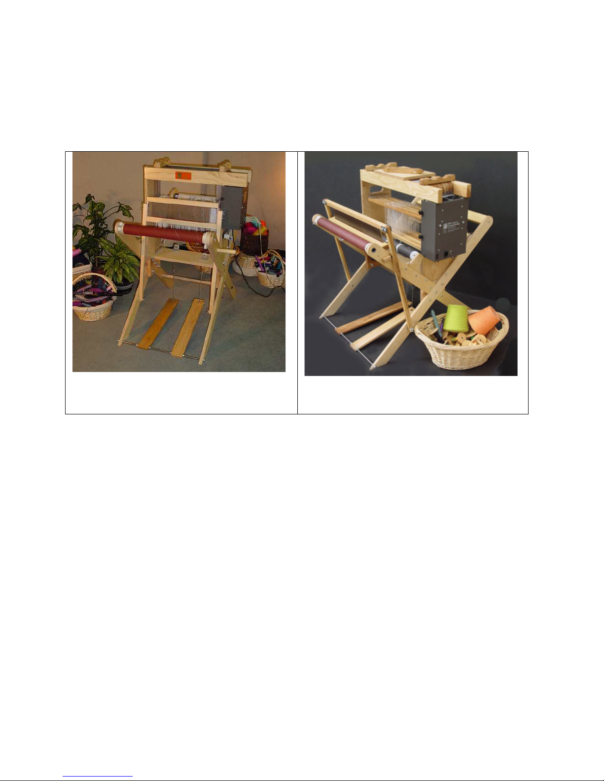
Figure 1 - 16" Workshop Dobby
Loom
AVL Looms
2360 Park Avenue
Chico, CA 95928-6785
800 626-9615
530 893-4915
530 893-1372 (fax)
Figure 2 - 24" Workshop Dobby
Loom
All Rights Reserved Worldwide
http:\\www.avlusa.com
e-mail: sales@avlusa.com
May 2018
Revision 1 Instructions
© Copyright 2018


Workshop Dobby Loom User’s Manual Introductory Information
Introductory Information ................................................................................................................ 1
Safety .......................................................................................................................................... 2
Introduction ................................................................................................................................. 4
WDL Specifications .................................................................................................................... 4
Parts............................................................................................................................................. 5
Tools You Will Need .................................................................................................................. 5
WDL Assembly ............................................................................................................................ 11
Assembly................................................................................................................................... 12
Interchangeable Design Unit (IDU) .......................................................................................... 15
Beater ........................................................................................................................................ 18
Treadles ..................................................................................................................................... 21
Beams ........................................................................................................................................ 23
Compu-Dobby® ....................................................................................................................... 28
Traveling with the WDL ............................................................................................................... 31
Traveling With Your Workshop Dobby Loom ......................................................................... 32
Using the WDL ............................................................................................................................. 37
Warping Section........................................................................................................................ 38
Threading, Sleying, and Tying On ............................................................................................ 50
Weaving Procedures ................................................................................................................. 53
Additional Loom Information ....................................................................................................... 55
Loom Maintenance ................................................................................................................... 56
Troubleshooting ........................................................................................................................ 57
The Fine Print ............................................................................................................................... 63
AVL Customer Service ............................................................................................................. 64
AVL Warranties ........................................................................................................................ 64
Notice to Users in the European Union .................................................................................... 65
ABLE OF CONTENTS
T
Table of Contents Page | i


Workshop Dobby Loom User’s Manual Introductory Information
INTRODUCTORY
INFORMATION
NTRODUCTORY INFORMATION
I
Introductory Information Page | 1
Introductory Information Workshop Dobby Loom User’s Manual
AFETY
S
Before Getting Started:
Please read the entire manual before using the loom.
Warnings:
WARNING:
EQUIPMENT SHOULD ONLY BE USED FOR TEXTILE MANUFACTURING. IF
THE EQUIPMENT IS USED IN A MANNER NOT SPECIFIED BY THE
MANUFACTURER, THE PROTECTION PROVIDED BY THE EQUIPMENT MAY
BE IMPAIRED.
WARNING:
ELECTRICAL SHOCK HAZARD. DO NOT TAMPER WITH ELECTRICAL WIRES
OR OPERATE THE LOOM WITH SAFETY PANELS OPENED OR REMOVED.
WARNING:
PINCH, CRUSH, AND FINGER CUT-OFF HAZARDS. DO NOT OPERATE THE
LOOM WITH SAFETY PANELS OPENED OR REMOVED. DO NOT PLACE
HANDS IN MOVING MECHANISMS OR SCISSORS.
Page | 2 Safety

Workshop Dobby Loom User’s Manual Introductory Information
WARNING:
EQUIPMENT PANELS ARE AWKWARD AND HEAVY. TO AVOID MUSCLE
STRAIN OR INJURY, USE PROPER LIFTING TECHNIQUES AND A HELPER.
WARNING:
DO NOT POSITION EQUIPMENT IN A WAY TO BLOCK OR IMPEDE ACCESS
TO DISCONNECTING DEVICES, EMERGENCY STOPS, OR ON/OFF BREAKER
SWITCHES
WARNING:
USE OF CONDUCTIVE FIBER OR YARN ON OR AROUND THIS EQUIPMENT
WILL VOID WARRANTY AND MAY DAMAGE EQUIPMENT.
WARNING:
THIS EQUIPMENT IS CLASSIFIED FOR LIGHT INDUSTRIAL ENVIRONMENT
ONLY. OPERATION OF HIGH-CURRENT DRAW EQUIPMENT (EX. MIG
WELDER) ON THE SAME ELECTRICAL CIRCUITS MAY CAUSE EQUIPMENT
FAILURE.
Safety Features:
Covers and shielding separate weaver from moving components where pinch
hazards exist. Do not reach under covers and shielding while the loom is
operating.
Safety Page | 3

Introductory Information Workshop Dobby Loom User’s Manual
NTRODUCTION
I
Congratulations on your purchase and welcome to the AVL family. Your
Workshop Dobby Loom (WDL) is designed to provide you with years of
enjoyable service. And, with your purchase, you are entitled to AVL’s world
class loom support. Please contact us with any questions at info@avlusa.com
or 1-530-893-4915.
This manual provides setup and use information for all current WDL loom
configurations, including:
16” weaving width (16” WDL)
24” weaving width (24” WDL)
8, 16, or 24 harness configurations
Single or double Warp Beam configurations
Please read the entire manual before starting the assembly process. Also,
please note which diagrams and sections are applicable to your loom.
WDL S
Weaving
Width
No. of Warp
Beams
Height 43-1/2”
Width 30-1/2”
Depth 39” (99.1
Weight 47 lbs. (22
PECIFICATIONS
16” (40.6
cm)
1 2 1 2
(110.5 cm)
(77.5 cm)
cm)
KG)
16” (40.6
cm)
43-1/2”
(110.5 cm)
30-1/2”
(77.5 cm)
46” (116.8
cm)
53 lbs. (24.1
KG)
24” (61
cm)
43-1/2”
(110.5 cm)
35-1/2”
(90.2 cm)
39” (99.1
cm)
77 lbs. (35
KG)
24” (61 cm)
43-1/2”
(110.5 cm)
35-1/2”
(90.2 cm)
46” (116.8
cm)
83 lbs. (37.7
KG)
Page | 4 Introduction
Workshop Dobby Loom User’s Manual Introductory Information
OOLS YOU WILL NEED
T
1. Allen wrench (provided)
2. Socket wrench, with 7/16” socket
3. Wrench (7/16”)
4. Philips screwdriver
5. Hammer (optional)
ARTS
P
Note:
Items marked with an asterisk (*) indicate that there will be an additional,
identical item if you ordered a two-beam system.
(1) Hardware Bag
(2) Beater Legs
(1) Travel Straps with Handle
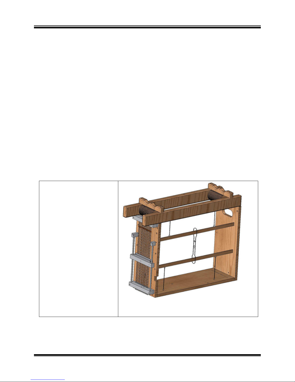
(1) Interchangeable
Design Unit (IDU):
harness pulley support,
harnesses, and dobby
Figure 3 - IDU
Tools You Will Need Page | 5

Introductory Information Workshop Dobby Loom User’s Manual
(4) X-frame legs (left
and right sets)
(2) Center Braces
Figure 4 - X-Frame Legs (4)
Note:
The X-Frame Legs are marked A, B, C, and
D. The holes for assembly are in different
places on each one. If you ordered a twobeam system, you will have legs E and F in
place of C and D. These legs are longer.
Figure 5 - Center Brace
(1) Cross Brace, Birch
hardwood plywood
(1) Reed Assembly includes Reed, Beater
Top and Beater Race
(2) Treadles (left and
right)
Figure 6 - Cross Brace
Figure 7 - Reed Assembly
Figure 8 - Left (longer)
Figure 9 – Right
Page | 6 Parts
Workshop Dobby Loom User’s Manual Introductory Information
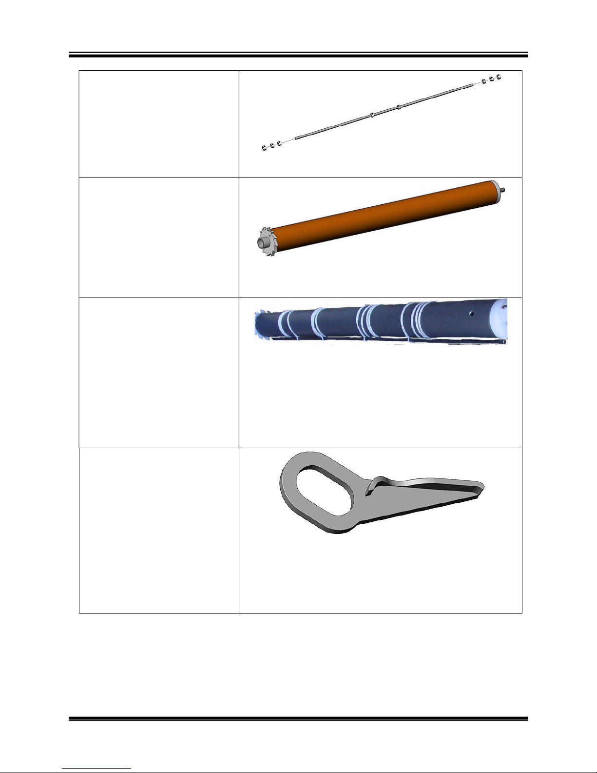
(1) Treadle Rod and Stop
Collars (8)
Figure 10 - Treadle Rod and Stop Collars
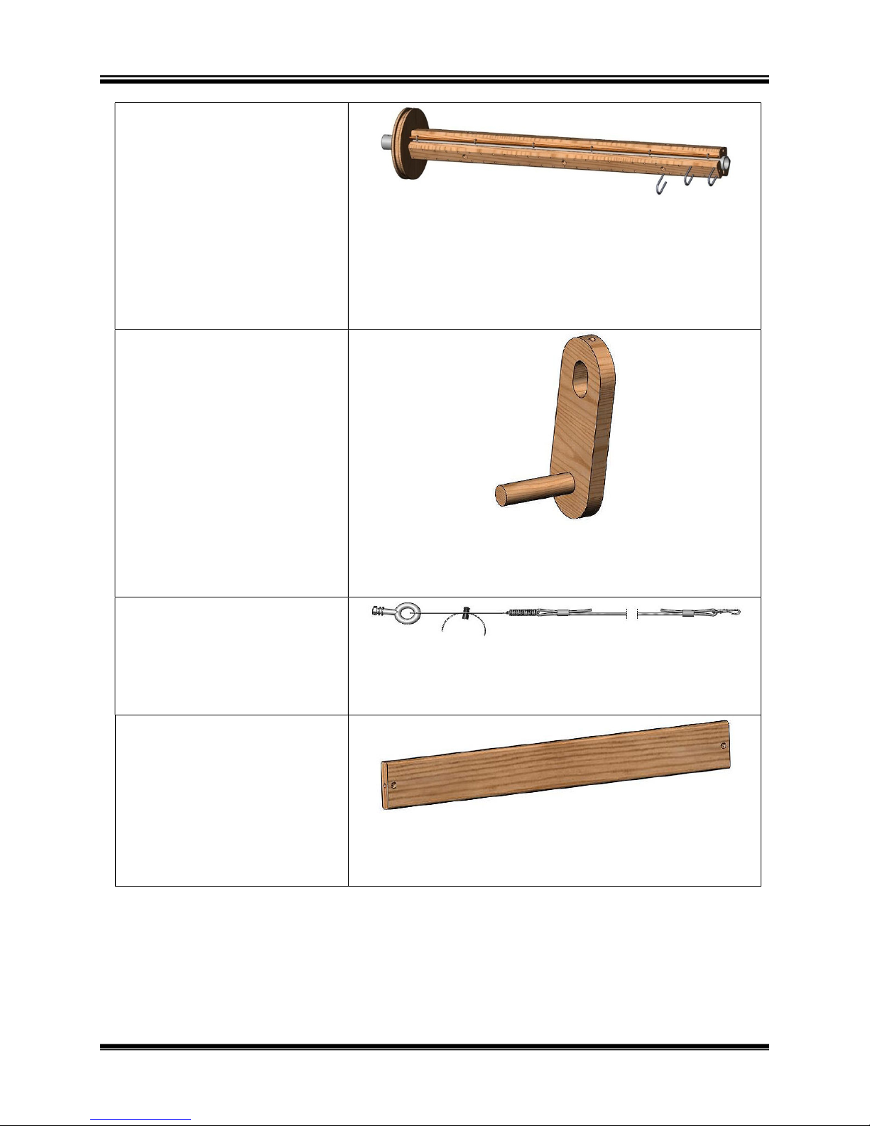
(1) Cloth Beam with
Ratchet
(1) Cloth Storage Beam
with Tie-On Rod and
Attaching Cords
(1) Cloth Beam Ratchet
Handle, aluminum
(1) Cloth Storage Beam
Ratchet Handle,
aluminum
Figure 11 - Cloth Beam with spacer on
right
Figure 12 - Cloth Storage Beam
Note:
The Cloth Storage Beam comes standard
only with the 24” WDL. If you ordered a 16”
WDL, you will not receive a Cloth Storage
Beam unless it was ordered as an option.
Parts Page | 7
Figure 13 - Ratchet Handle
Note:
You will only receive a Cloth Storage Beam
handle if you received a Cloth Storage Beam.
Introductory Information Workshop Dobby Loom User’s Manual
(1) Warp Beam with
Brake Drum*
(1) Warp Beam Handle,
wood*
(1) Tension Tie-Up
Assembly for Warp
Beam*
Figure 14 - Sectional / Plain Beam
Note:
To use as a sectional warp beam, insert
metal hoops. To use as a plain beam, remove
the metal hoops.
Figure 15 - Warp Beam Handle
Figure 16 - Tension Tie-Up Assembly
(1) Separation Beam,
solid Ash hardwood*
Figure 17 - Separation Beam
Page | 8 Parts
Workshop Dobby Loom User’s Manual Introductory Information
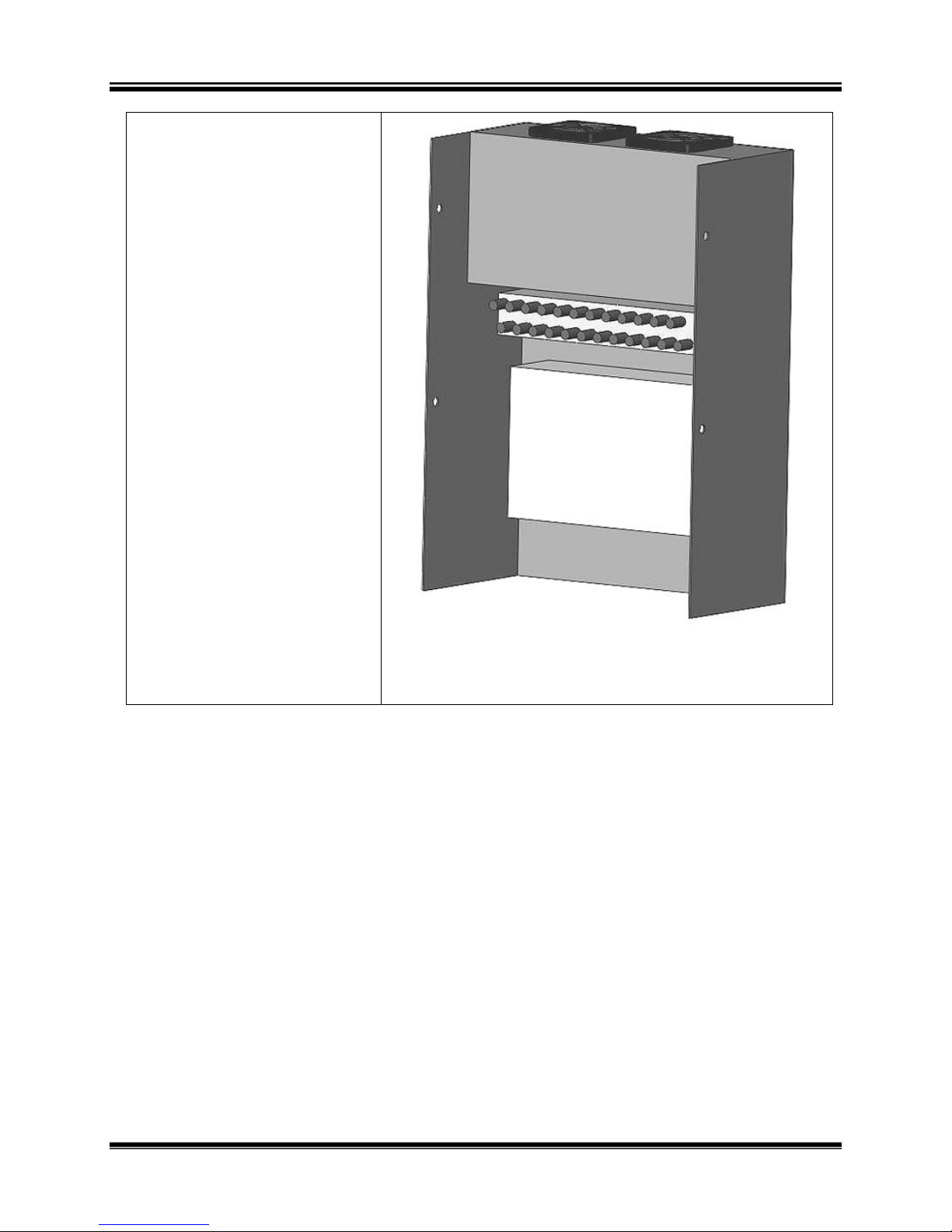
(1) Compu-Dobby® with
Cables
Figure 18 - Compu-Dobby
Parts Page | 9


Workshop Dobby Loom User’s Manual WDL Assembly
WDL ASSEMBLY
WDL A
SSEMBLY
WDL Assembly Page | 11
WDL Assembly Workshop Dobby Loom User’s Manual
SSEMBLE THE
A
X-F
RAME
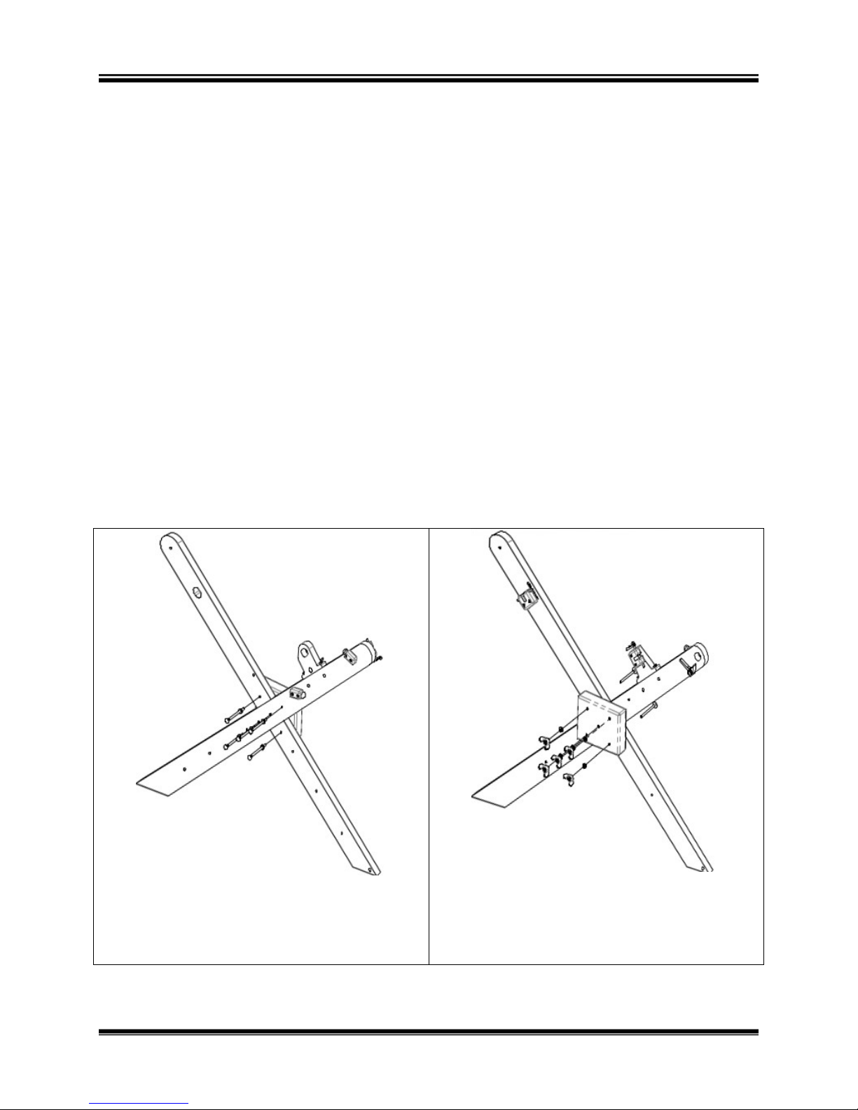
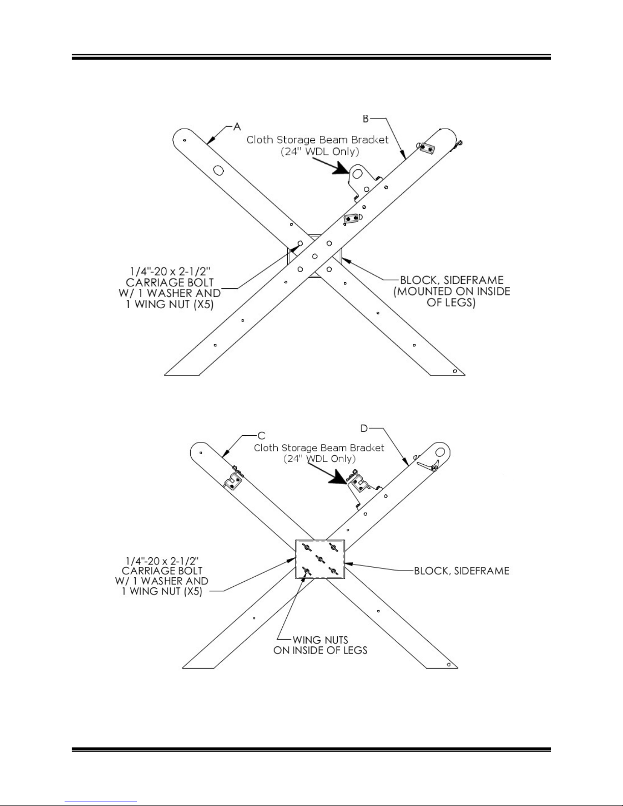
X-Frame sides:
1)
2)
Note:
The Cloth Beam Bracket is on the inside of the frame.
3)
4)
For the left side you will need legs A and B. If you are assembling
the frame for the two-beam version, use legs B and E. Fit the legs
together at the notch in the center
Slide a 2-1/2” carriage bolt from the outside through the center
hole at the crossing of the legs.
Slide a Center Brace onto the bolt. Install a washer and wing nut,
and tighten to ‘finger tight’ condition.
Repeat this process for the remaining four holes using the 2 1/2”
carriage bolts, washers and wing nuts to fully secure the Center
Brace to the legs.
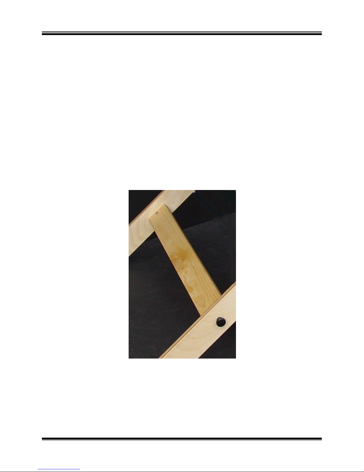
Figure 19 - X-Frame Bolts from
Outside
5)
Page | 12 Assemble the X-Frame
Tap carriage bolt heads with a hammer until flush to the legs.
Figure 20 - X-Frame Bolts from
Inside
Workshop Dobby Loom User’s Manual WDL Assembly
6)
Repeat these steps for the right side using legs C and D. Use legs D
and F for the two-beam frame.
Figure 21 - X-Frame Outside (Left)
Figure 22 - X-Frame Inside (Right)
Assemble the X-Frame Page | 13
WDL Assembly Workshop Dobby Loom User’s Manual
Cross Brace Installation
IMPORTANT:
The Cross Brace is plywood and should not be confused with the solid wood
Separation Beam.
1)
2)
3)
The X-Frame should now stand without support.
Attach the Cross Brace to the inside of the Right Side and secure
with black thumbscrew (long) from the outside of the leg.
Stand the Left and Right Sides approximately 17” apart (for the 16”
WDL) or 25” apart (for the 24” WDL) with Center Braces facing
each other.
Secure the Cross Brace to the Left Side with a black thumbscrew
(long) from the outside of the leg.
Figure 23 – X-Frame Cross Brace
Page | 14 Assemble the X-Frame
Workshop Dobby Loom User’s Manual WDL Assembly
NTERCHANGEABLE DESIGN UNIT
I
(IDU)
Install the IDU
1)
Set the IDU onto the Center Braces inside the X-Frame so that the
Dobby is on the right side of the loom.
Figure 24 - WDL with IDU
2)
Note:
As before, the bolts are inserted from the outside through the X-Frame and
through the IDU.
Secure the IDU to the X-Frame using the (4) 2” carriage bolts,
washers and wing nuts.
3)
NOTE:
A light tap with a hammer on the end of the bolt may be used to help seat the
bolt.
Interchangeable Design Unit (IDU) Page | 15
Tighten all the wing nuts so that the square part of the carriage bolt
head sinks into the outside of the X-Frame.
WDL Assembly Workshop Dobby Loom User’s Manual
HANGING THE HARNESSES ON THE IDU
Review the lay of the harness cables to make sure that they are arranged on
their proper pulleys. Cable ends should hang freely over the pulleys and
down inside the IDU.
Heddles:
You have been supplied with 25 heddles per harness plus 200 extra. You can
purchase additional heddles from AVL. Heddles are shipped in bundles of
100.
You can divide the bundle of 100 heddles into smaller bundles to place on the
harness. Without removing the original twist-ties, count out the number of
heddles you want on the harness. Place a new twist-tie around each smaller
bundle. Remove the original twist tie and cut the smaller bundles apart.
1)
Insert an Eye Hook Retainer Tube over each harness cable loop and
up above the crimped Nico. You will slide the eye hook retainer
back down over the loop once it has been hooked onto the harness
stick.
2)
Figure 25 - Eyehook cover on Harness
Lay two harness sticks flat on a table or floor with the screw eyes
facing away from each other.
Page | 16 Interchangeable Design Unit (IDU)
Workshop Dobby Loom User’s Manual WDL Assembly
Figure 26 - Parallel Harness Sticks
3)
Slide the top harness stick through the loop at one end of a heddle
bunch, then slide the bottom harness stick through the opposite
loop of the heddle bundle.
Figure 27 - Place heddle bundle on heddle sticks
4)
5)
Remove the ties on the bundles.
Now clip the loops of your heddles -- it is easier to cut the loops
when your harnesses are off the loom. You now have one harness.
Figure 28 - Cut heddle loops
Interchangeable Design Unit (IDU) Page | 17

WDL Assembly Workshop Dobby Loom User’s Manual
Hang the Harnesses
When hanging the harnesses, start at the rear most harness position and
work forward.
1)
2)
3)
EATER ASSEMBLY
B
The Reed Assembly (as typically delivered from the factory) is the Beater
Top, Reed, and Race, pre-assembled and secured with strapping tape. The
strapping tape should be removed before the Reed Assembly is attached to
the Beater Legs. The WDL Beater Race faces the front of the loom. You will
put together the Beater Assembly first, and then put it on the loom.
Holding the top harness stick, lift the Harness and hook the left and
right harness cables to the eyehooks on the top harness stick. The
harness will hang from the IDU.
Attach the correct harness springs to the eyehooks on the bottom
harness stick.
Repeat these steps for the remaining harnesses.
1)
Locate the Beater Legs and Reed Assembly.
Figure 29 - WDL Beater
Page | 18 Beater Assembly

Workshop Dobby Loom User’s Manual WDL Assembly
2)
Each leg has a straight side and a tapered side. Place the legs so
that the tapered side is to the outside.
3)
4)
Separate the Beater Top and Reed from the Race.
Place the Beater Race so that the cut-out sides lock around each leg
and the holes are aligned.
5)
6)
Slide a carriage bolt through each of these holes from the front.
Insert a washer and secure with a nut. Do not tighten the nuts yet.
Repeat for each hole on both sides.
7)
Use a small square to make sure the Beater Race is square to the
Beater legs. Adjust as needed before securing the bolts.
8)
Set the Beater Top and Reed onto the Race with the cut-outs on the
sides facing the legs.
9)
Slide a bolt from the back of the beater through the slot in the leg,
continuing through the hole in the Beater top.
10) Insert a washer and secure with a wing nut. Repeat for the other
side.
Beater Assembly Page | 19

WDL Assembly Workshop Dobby Loom User’s Manual
To install or change the Reed:
1)
Remove the wing nuts from the bolts holding the Beater Top to the
Beater Legs.
2)
3)
4)
5)
Lift off the Beater Top.
Insert and seat the Reed into the Beater Bottom
Slide the Beater Top down and seat it on the Reed.
Re-install the hardware to secure the Reed.
NOTE:
If you have room, it is generally easier to transport the beater as a unit, rather
than disassemble it.
To place the Beater Assembly on the loom:
1)
Place a carriage bolt through the hole at the front bottom of the Xframe on each side.
2)
3)
Place a washer on each bolt.
Position the Beater Assembly on the loom so that the slot at the
bottom of the legs is over the bolt on each side.
4)
Place another washer and a nut on each bolt to hold the Beater
Assembly to the loom.
5)
When the beater is pushed back and pulled forward, both sides
should hit the bumpers at the same time. If they do not, check that
the beater is square. You may also need to adjust the tightness of
the bolts holding the beater to the loom.
Page | 20 Beater Assembly

Workshop Dobby Loom User’s Manual WDL Assembly
READLES
T
The metal Treadle Rod comes with eight stop collars. The inner-most two
stop collars are pre-located for your convenience. They are not
symmetrically placed on the Treadle Rod.
1)
2)
3)
Remove the outer three stop collars on each side with the 1/8”
Allen Wrench. The two inner stop collars are locked in the correct
position for your loom.
Slide the Right Treadle (shorter treadle) onto the shorter end of the
Treadle Rod with the Treadle Cable up.
Slide the Left Treadle (longer treadle) onto the longer end of the
Treadle Rod with the Treadle Cable up.
Figure 30 - Left and Right Treadles
4)
5)
Slide a stop collar onto each end of the rod and loosely position
them next to the treadles.
Tighten the stop collar into place using an Allen Wrench. You now
have the Treadle Assembly.
Treadles Page | 21

WDL Assembly Workshop Dobby Loom User’s Manual
NOTE:
There should be enough space left between the stop collar and the treadle to
avoid binding the treadle movement.
6)
Place the Treadle Assembly under the front of the loom with Treadle
Cables facing up and directly beneath the IDU.
7)
8)
Figure 31 - WDL treadle positioning
Slide another stop collar on each side of the Treadle Assembly, and
leave it loose for later adjustment.
Slide the left end of the rod into the hole on the lower front left XFrame leg; slide the right end of the rod into the hole on the lower
front right X-Frame leg.
9)
Slide a stop collar onto each end of the rod. The X-Frame legs
should be sandwiched by stop collars.
Page | 22 Treadles

Workshop Dobby Loom User’s Manual WDL Assembly
10) Adjust the four stop collars until they are snug against the X-Frame
and tighten.
11) Unclip the cables from under the IDU.
12) Clip the left hanging cable from IDU to the left Treadle Cable and
the right hanging cable from IDU to the right Treadle Cable.
13) These cables connect the treadles to the dobby.
Depressing the right Treadle raises the Harnesses. Depressing the left
Treadle signals the Compu-Dobby® to advance to the next pick.
NOTE:
While rare, it has been noted that the Treadle Cable pulleys located inside the
bottom shelf of the IDU can loosen during travel and/or very heavy weaving. It
is a good practice to routinely check the pulley bracket screws for tightness
and verify that the cable retainer brackets are seated flush on the pulley and
the retaining bolts are also tight.
EAMS
B
The Cloth Beam
The Cloth Beam (or sandpaper beam) with Ratchet is inserted in the front of
the loom. For the 24” WDL, the upper position is used.
1)
2)
3)
4)
5)
Place the Ratchet handle on the ratchet end of the beam.
Hold the Ratchet handle so it is horizontal while placing the beam
on the loom. The long straight side of the handle should go to the
front of the loom.
Slide the beam end with the ratchet into the hole on the right front
frame leg.
Slide the other end of the beam into the Cloth Beam Retainer
Bracket on the other leg.
Insert the retainer pin into the Cloth Beam Retainer Bracket and
secure with a small pin.
Beams Page | 23

WDL Assembly Workshop Dobby Loom User’s Manual
Figure 32 -WDL Beams
The Warp Beam
The Warp Beam goes on the back of the loom.
1)
2)
3)
4)
Slide the beam end with the brake drum into the hole on the back
frame leg
Slide the other end of the beam into the Beam Retainer Bracket on
the other leg.
Insert the retainer pin into the Beam Retainer Bracket and secure
with a small pin.
Place a washer on the Tension Tie-Up Assembly eye-bolt.
Page | 24 Beams

Workshop Dobby Loom User’s Manual WDL Assembly
5)
6)
7)
8)
NOTE:
The cord should not overlap itself on the drum.
From the inside of the X-Frame, insert the eye-bolt of the Tension
Tie-Up Assembly into the hole near the IDU on the lower left leg of
the X-Frame and secure with another washer and nut.
Wrap the Tension Tie-Up cord over and down the rear side of Warp
Beam Brake Drum.
Wrap the cord around the drum twice working towards the center of
the loom. The cord wraps counter-clockwise if you are looking at
the drum from the left side of the loom.
Extend the cord back down to the eye-bolt and clip it on.
The Separation Beam
The Separation Beam is located at the upper rear of the X-Frame and is
secured with Phillips-head screws.
IMPORTANT:
The Separation Beam is solid wood and should not be confused with the
plywood Cross Brace.
1)
2)
Insert the Separation Beam between the upper rear members of
the X-Frame
Secure with Phillips-head screws from the outside of the leg.
The Cloth Storage Beam (24” WDL Only)
The Cloth Storage Beam is inserted in the front, lower position on the XFrame, just in front of the IDU. The Cloth Storage Beam is included with the
24” WDL only. It is available as an option for the 16” WDL.
1)
2)
3)
Place the Ratchet handle on the ratchet end of the beam.
Hold the Ratchet handle so it is horizontal while placing the beam
on the loom. The long straight side of the handle should go to the
back of the loom.
Slide the beam end with the ratchet into the hole on the left front
frame leg.
Beams Page | 25

WDL Assembly Workshop Dobby Loom User’s Manual
4)
Slide the other end of the beam into the Beam Retainer Bracket on
the other leg.
5)
Insert the retainer pin into the Beam Retainer Bracket and secure
with a small hair pin.
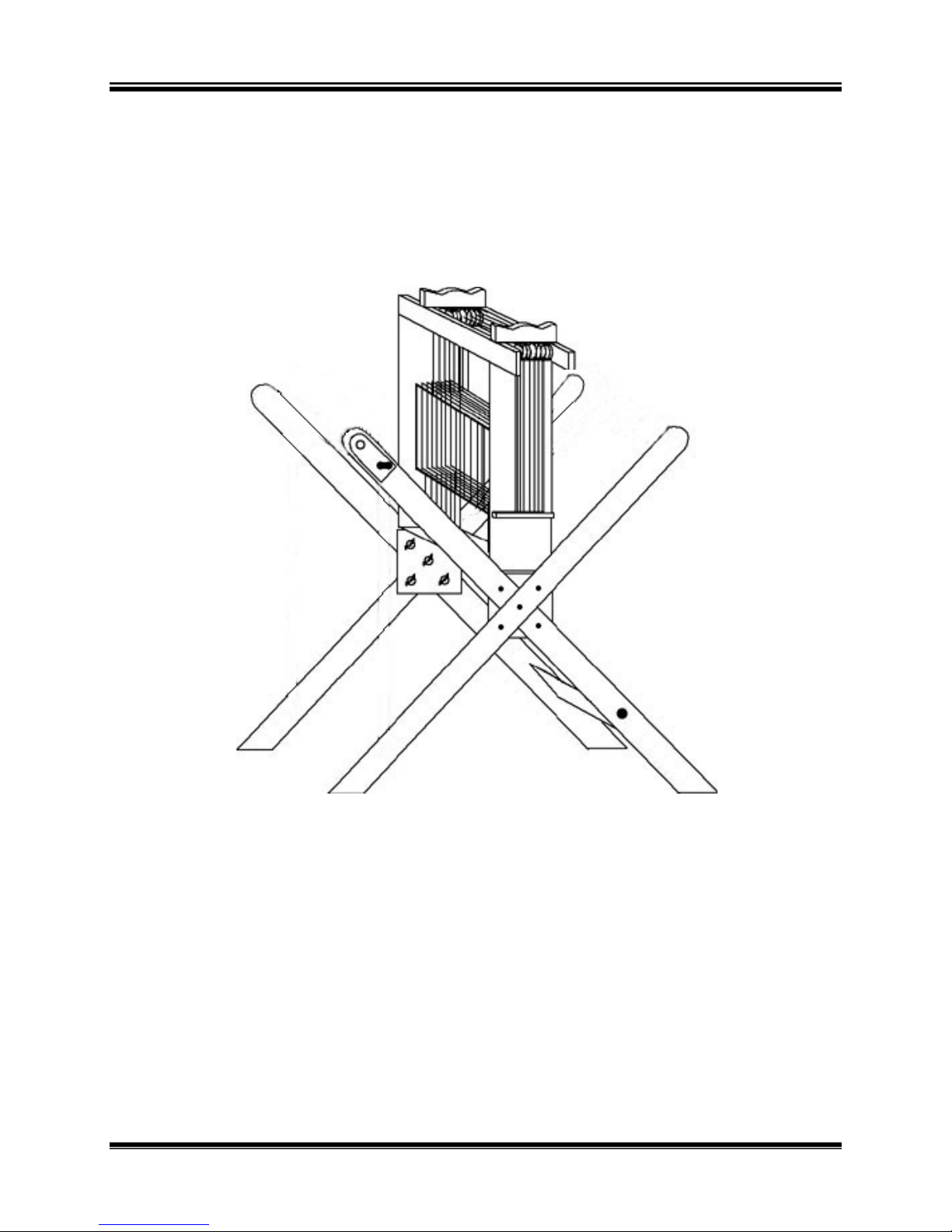
Two-Beam
The Two-Beam system has longer left and right legs that allow room for the
additional beam. To switch to the two-beam system, disassemble the Xframe and reassemble it using the longer legs (E and F).
Figure 33 - WDL with two beams
1)
2)
Place the top warp beam into position as described earlier.
Place the lower warp beam into position.
Page | 26 Beams

Workshop Dobby Loom User’s Manual WDL Assembly
3)
Attach the tension tie-up assembly for the upper beam using the
lower eye-bolt.
4)
Attach the tension tie-up assembly for the lower beam using the
upper eye-bolt.
Figure 34 - WDL with two beams
5)
Insert a separation beam for each warp beam. The upper
Separation Beam is used for the upper beam and the lower
Separation Beam is used for the lower beam.
Beams Page | 27

WDL Assembly Workshop Dobby Loom User’s Manual
OMPU
C
The Compu-Dobby® is packed with a wood backing plate. This plate also
serves as a tool tray when set upon the IDU. The Compu-Dobby is installed
on the right side of the IDU.
1)
On the loom, find the strap holding the dobby slide plate in place.
OBBY®
-D
2)
Note:
When traveling with, or shipping, your loom, please strap the Dobby Slide
Plate in place so that it cannot move.
3)
4)
NOTE:
Always travel or ship the Compu-Dobby with the wood backing plate in place
to provide the best possible protection. Take care to save the barrel nuts
inserted in the backing plate as these are used with the thumbscrews to hold
the board to the Compu-Dobby.
Cut the strap and remove it so that the Dobby Slide Plate moves
freely.
Remove the wood backing plate from the Compu-Dobby by
removing the 4 black thumbscrews (short).
Place the wood backing plate on the top of the IDU with the metal
dowels facing down and inserted in the matching holes on the IDU.
Page | 28 Compu-Dobby®

Workshop Dobby Loom User’s Manual WDL Assembly
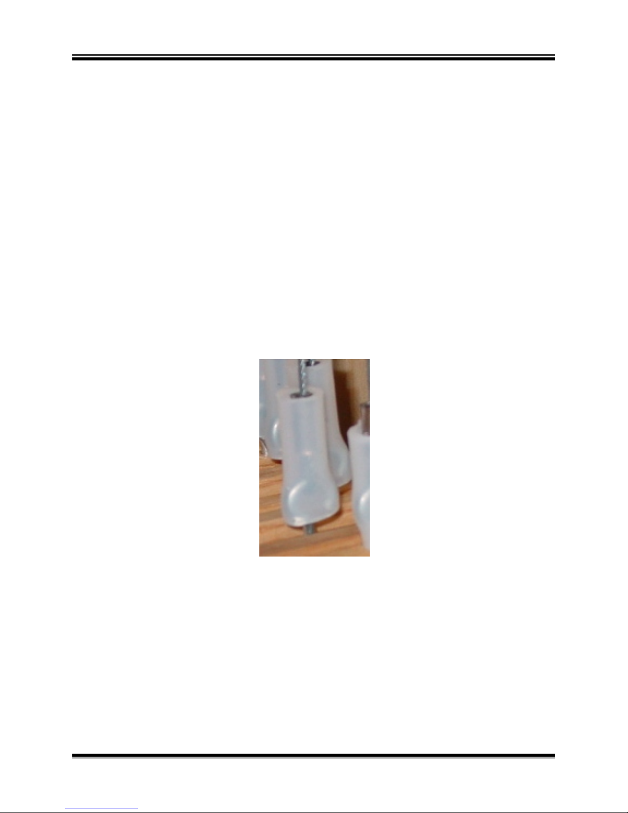
5)
Align each plastic solenoid tip in the Compu-Dobby such that the
“U” or concave indentures of the tips aligns in a vertical orientation.
Figure 35 - Compu-Dobby Solenoids
NOTE:
In this orientation, the solenoid tips will cradle the Dobby Wires and ensure
that the solenoids properly capture and engage the Dobby Wires.
6)
While carefully avoiding jostling the solenoid tips from their
orientation, place the Compu-Dobby onto the IDU, aligning the
holes on the Compu-Dobby and the IDU, and secure with the 4
black thumbscrews (short).
Figure 36 - WDL with Compu-Dobby
Compu-Dobby® Page | 29

WDL Assembly Workshop Dobby Loom User’s Manual
Connecting Your Compu-Dobby® To Your Computer
1)
2)
NOTE:
AVL strongly recommends that you use a surge protector with your CompuDobby.
3)
Plug the female end of the Compu-Dobby power cord into the
Compu-Dobby.
Plug the male end of the Compu-Dobby power cord into your power
source (wall outlet).
Attach the USB cable between the Compu-Dobby and your
computer.
Loom Software
Many software providers have developed drivers for the AVL Compu-Dobby.
Make sure the software you choose will correctly run your Compu-Dobby
version and number of harnesses.
AVL offers a feature rich design and loom control program for Windows
computers: WeavePoint. It comes with the exact loom driver needed to run
the Compu-Dobby with your number of harnesses. You can download a
demo of WeavePoint at http://www.weavepoint.com/.
You will need to setup the software to communicate with your CompuDobby. Please refer to the manual for the software you’ve chosen for help
with this.
Page | 30 Compu-Dobby®

Workshop Dobby Loom User’s Manual Traveling with the WDL
TRAVELING WITH
THE WDL
RAVELING WITH THE
T
WDL
Traveling with the WDL Page | 31

Traveling with the WDL Workshop Dobby Loom User’s Manual
RAVELING
T
When traveling with your WDL, it is a good idea to replace loose hardware
on the loom or to put it in a sealable plastic bag and pack it with your tools.
ITH YOUR
W
ORKSHOP DOBBY LOOM
W
24” WDL Disassembly
Remove the Compu-Dobby
1)
2)
3)
4)
Turn off the Compu-Dobby, unplug the power cord from your outlet
and the Compu-Dobby and coil up the power cord for travel.
Disconnect the cable from the Compu-Dobby and your PC and coil it
up for travel.
Remove the Compu-Dobby from the IDU and set it down.
Remove the shuttle tray/wood backing plate from the top of the
IDU (the one that originally came attached to the back of the
Compu-Dobby).
5)
6)
Remove the beater
1)
2)
Attach the wood backing plate to the back of the Compu-Dobby.
Strap the Dobby Slide Plate in place on the loom.
Remove the bolts securing the Beater Top to the Beater Legs and
remove it from on top of the Reed.
Lift the Reed out of the Race and secure it inside the IDU. Make
sure the Reed Assembly is positioned vertically.
Page | 32 Traveling With Your Workshop Dobby Loom

Workshop Dobby Loom User’s Manual Traveling with the WDL
Figure 37 - 16" WDL with Compu-Dobby removed
Remove the beams
1)
2)
Disengage the Cloth Beam ratchet.
For the 16” WDL:
a. Roll any loose fabric onto the Cloth Beam and place it on top
of the IDU in the front beam rest cradle.
3)
For the 24” WDL with the Cloth Storage Beam:
a. Roll any loose fabric onto the Cloth Storage Beam.
b. Disengage the Cloth Storage Beam ratchet.
c. Remove the Cloth Storage Beam and place it on top of the
IDU in the front beam rest cradle.
d. Set the Cloth Beam aside for packing.
Traveling With Your Workshop Dobby Loom Page | 33

Traveling with the WDL Workshop Dobby Loom User’s Manual
Note:
If you have a 2-beam setup, complete steps 7-10 for the upper separation
beam and warp beam, then repeat them for the lower separation beam and
warp beam. Place the additional warp beam on top of the two beams on the
IDU to create a pyramid.
4)
Unclip the Tension Tie-Up from the screw eye on the back right leg
and unwrap it from the Warp Beam Drum.
5)
6)
Remove the Separation Beam from its mounting.
Remove the Warp Beam, carefully wrapping any loose warp around
it, and place it on top of the IDU in the rear beam rest cradle.
Figure 38 - 16" WDL with beams removed
7)
To hold the beams in place, loop the two straps under the IDU and
around the beams. Then feed the loose end of the straps into each
of their buckles.
Page | 34 Traveling With Your Workshop Dobby Loom

Workshop Dobby Loom User’s Manual Traveling with the WDL
Remove the IDU and disassemble the frame
1)
2)
3)
Unclip the left and right Treadle Cables from the IDU.
Unscrew the four wing nuts holding the IDU to the X-Frame.
Lift the IDU out of the X-Frame and place on the ground on its
rollers. It is now ready to roll.
Figure 39 - 16" WDL with beams tied in place
4)
Loosen the two outside stop collars on the Treadle Rod. Remove the
Treadle Assembly from the X-Frame.
5)
If you need to break down the Treadle Assembly further for travel,
remove the next two sets of stop collars and remove the Treadles.
Note:
Always leave the inner stop collars on the Treadle Rod to avoid having to
adjust these at re-assembly.
Traveling With Your Workshop Dobby Loom Page | 35

Traveling with the WDL Workshop Dobby Loom User’s Manual
6)
For packing, replace the stop collars back onto the rod and tighten
the outside stop collars to retain them.
7)
Remove the Beater Assembly as a whole if you can transport it. If
needed, unbolt the Race from the Beater Legs and remove them
separately.
8)
9)
Remove the Cross Brace and Separation Beam from the X-Frame.
Disassemble the X-Frame.
NOTE:
The X-Frame can be completely disassembled and re-packed into the box it
was shipped in.
Now, you are ready to pack up your WDL for travel.
Reassembly (For 16” or 24” WDL)
When re-assembling your beams, keeping tension is important.
1)
2)
3)
Reassemble the X-Frame and replace the IDU.
Attach the treadles to the treadle cables.
Install the Warp Beam first. If you are using the two-beam system,
replace the lower warp beam first, then the upper warp beam. The
beams should be on the pyramid on top of the IDU in this order.
4)
Install the Cloth Beam. For the 24” WDL, install the Cloth Storage
Beam next. Carefully unroll the warp as you bring the beam from
its IDU cradle to its mounting location.
5)
6)
Replace the reed assembly on the beater.
Replace the Compu-Dobby on the IDU.
NOTE:
During this process, keep the warp square and with some tension to create
as little disturbance to your warp as possible.
Page | 36 Traveling With Your Workshop Dobby Loom

Workshop Dobby Loom User’s Manual Using the WDL
USING THE WDL
SING THE
U
Note:
Unless otherwise noted, the instructions in this section are basic, general
instructions for weaving and are applicable to many AVL and non-AVL looms.
They should not be regarded as a substitute for training or experience.
WDL
Using the WDL Page | 37

Using the WDL Workshop Dobby Loom User’s Manual
ARPING SECTION
W
AVL advocates warping from back to front. We believe that this system
works best with our looms and our warping tools are designed around this
philosophy. If you prefer other warping methods, you will be able to adapt
them to work on your new loom. However, we suggest you study the
following warping techniques and try them out to get the most out of the
Workshop Dobby Loom.
To learn more about your AVL loom and to learn how to get the most out of
it, you may want to take a class at the AVL Weaving School. Complete
information and a current class schedule can be obtained by phoning the
AVL office (1 800 626-9615 or 530 893-4915) or on-line at
http://www.avlusa.com/workshops.
Tying onto the Warp Beam
The WDL comes with a sectional beam that can be used as a plain beam
when the metal hoops are removed. You might want to make a permanent
set of Extension Cords to use when warping the Beam. Extension Cords are
also called “apron cords” and serve the same function as the apron on other
Plain Beams. They give you “reach” from the Warp Beam and allow you to
weave every possible inch until the end of the warp touches the last Harness
you are using. Make them out of a strong non-stretchable linen or cotton
cord. You will need to make one Extension Cord for each section of your
warp. When using the beam as a sectional beam, this will be one cord per
section. Using the same number for the sectional beam and the plain beam
will work well. For each Extension Cord:
1)
2)
Measure a piece of cord long enough to reach from the axle of the
Warp Beam, at least one and a half revolutions around the Beam
and then reach to the back most Harness.
When measuring the length of the cords, take into account that,
when the warp is attached to the Extension Cord the knot between
the cord and the warp needs to fall between the Crosspieces of the
Sectional Beam, not on them. This will keep the warp smooth on
the Beam so it doesn’t go over the knots created when attaching
the warp to the cords.
3)
Page | 38 Warping Section
Now double that length and cut it. All Extension Cords should be
exactly the same length, so cut them all at the same time.

Workshop Dobby Loom User’s Manual Using the WDL
4)
5)
6)
Take the two ends of the cord and knot them together, using an
overhand knot.
Wrap the cord around the center bar of the sectional beam with a
larks head knot. You will also use a larks head knot to secure the
warp threads to the extension cord.
Route the extension cords in a “Z” shape, from under the Warp
Beam up and over the Separation Beam to the rear of the loom and
under the Warp Beam, when looking from the left side of the loom.
Adjusting the Tension Device on the WDL
Before winding on the warp, check the tension device to make sure the rope
is wrapped twice around the tension drum and that the rope end is clipped
to the eyebolt. This will prevent the warp beam from slipping backwards
during winding and threading.
Warping the Plain Beam
To warp a plain beam we recommend the following method in which the
warp is wound on with the use of a Raddle. We have found that this method
aids in getting a uniform warp tension, especially when dealing with long
warps.
Creating Two Crosses
To begin, wind the warp on a warping board or reel. Make sure you put in
two crosses, one at each end of your warp:
1)
2)
The Threading Cross (each thread crosses the next thread in
opposite directions; all are secured in a single loop).
The Raddle Cross (warp threads are tied in groups, depending on
how many ends will be put in each section of the raddle).
Warping Section Page | 39

Using the WDL Workshop Dobby Loom User’s Manual
Figure 40 - Warping Board with Two Crosses
Securing the Crosses
Before removing the warp from the board or the reel, secure the crosses.
Use four ties to secure each cross. These ties go on each side of both pegs
holding the cross.
It is usually a good idea to use different color threads for the ties on the tops
of the pegs and another color to tie the bows underneath the pegs. By color
coding your ties, you are less likely to twist the warp later.
Removing the Warp for the Warping Boards
Remove the warp from the warping board by chaining or by winding on the
kitestick. Start from the threading cross and proceed to the raddle cross.
Since the capacity of the warping board is limited, for wide warps you will
end up making a number of mini-warps and taking them off individually.
Page | 40 Warping Section

Workshop Dobby Loom User’s Manual Using the WDL
Attaching the Raddle
Now secure the raddle to the back of the loom.
Sticks in the Raddle Cross
Place two lease sticks in the raddle cross and secure together with string
through the holes in the ends of the sticks. Now remove the ties from the
raddle cross and spread the warp out on the sticks.
Measure the center of your raddle to use it as a center of your warp. The
warp threads should go through the middle of the raddle.
Feeding the Raddle
To feed the raddle, distribute yarns through the raddle by dropping each
raddle cross group into a dent in the raddle.
Figure 41 - Raddle
Warping Section Page | 41

Using the WDL Workshop Dobby Loom User’s Manual
If you are using an AVL raddle with a sliding cover, slide it on after the
raddle is threaded and secure it with two or three cord ties so it can’t come
off. Remove the raddle cross sticks when this is completed.
Preparing the Paper
Prepare the paper for winding between the warp layers. Again, for the most
professional results, and fewer tension problems, we suggest that the warp
be as smooth, tight, and compact as possible. This would mean not using
corrugated paper or sticks as they will make the warp too fat and/or lumpy.
Corrugated paper is just too soft and the warp can never be wound tight
enough with it. Heavy wrapping paper works well; seventy pound craft paper
is good. If you are going to be using smooth, slippery warp yarns like fine
linens or perle cottons, the edge yarns are going to need extra help in order
not to slip off.
Figure 42 - Prepared Paper with Folded Edge
To do this, cut your paper 4” wider than the warp width and then fold over
the edges an inch on each side. Be sure the warp is wound between the two
folded edges not overlapping them.
Winding the Warp On
NOTE:
From the left side of the loom, the warp is wound onto the beam by turning in
the counter-clockwise direction.
Before you start winding the warp onto the warp beam, attach the section of
the warp to an extension cord. To do so, tie an overhead knot in the warp
threads from one section and slip that knot into the opening of the larkshead
knot you created in the extension cord. Pull it tight.
Page | 42 Warping Section

Workshop Dobby Loom User’s Manual Using the WDL
When winding the warp on from the back, i.e., with the warp spread out in
back of the loom, turn the crank in a counterclockwise direction so that the
warp comes in from the bottom.
Remember; wind the warp on tightly under a lot of tension. This will vary
with each warp material, but a good rule to remember is that the tension of
the wound on warp must be greater than the tension during the weaving
operation. You will need one person to hold a warp under tension on the
back and one person to wind the warp on the beam using a handle. The
person winding the warp can also insert the paper.
If you have to do it yourself, you can use the jerking method. Make one turn
around with your beam crank and then go to the back of the loom and jerk
one section at a time to make the warp that is already on the beam tight.
The idea of this method is that the warp does not need to be under tension
all the time, but the part that is on the beam has to be tight. Make another
turn, go to the back of the loom and jerk all the sections again and so on. If
you have a wide warp, you might need to do up to ten jerking motions after
each turn.
Threading Cross
When you come to the end of your warp, insert lease sticks in your
threading cross.
Remove the Raddle
Now remove the ties from each individual threading cross and spread the
warp out on the sticks.
When the warping is completed, free the warp from the raddle. If you have
an AVL raddle, first untie the security strings, lift the raddle top off, and
remove the warp from the raddle. Afterwards, replace the top on the raddle
and leave it in its place on the back of the loom if so desired as it will not
interfere with the weaving process. Then be sure to bring the end of the
warp around the separation beam so that it now travels into the loom.
Warping Section Page | 43

Using the WDL Workshop Dobby Loom User’s Manual
Warping the sectional beam
The WDL Sectional Beam can be warped in sections using a Warping Wheel.
Throughout the warping process, the Warping Wheel automatically keeps a
constant and uniform tension on the warp.
Using the Warping Wheel
The Setup
1)
2)
Adjust height so position of mini-raddle is just below eye level.
Adjust the wind-off tension with toggle and cord. Tie cord to
prevent slipping.
Figure 43 - Adjust Wind-off Tension
3)
4)
5)
Adjust the warp length by moving the spools on the arms.
Reset the Revolution Counter to Zero
Setup Cones with the Cone Caddy
Making the First Section
6)
Open and secure the raddle top using the removable pin.
Page | 44 Warping Section

Workshop Dobby Loom User’s Manual Using the WDL
7)
Slide the thread(s) under the metal catch clip, tails facing to the
left. Tails should be about 5 inches long.
Figure 44 - Catch Thread Ends
8)
Bring the thread(s) up and over the left side of the top spool so that
you are ready to wind the Warping Wheel in a counter clockwise
motion.
9)
Continue in this manner until you have the number of threads you
need for the section.
Figure 45 - Wind Counter Clockwise
10) After you have wound one length bring the thread(s) around the
back of the raddle and through a dent (working from right to left).
Warping Section Page | 45

Using the WDL Workshop Dobby Loom User’s Manual
Figure 46 - Bring Thread through Raddle
11) Bring thread(s) down over the end you just wound and secure in
the silver clip (swooping under from left to right).
Tying Off
12) Put the raddle top back on. Cut the bout threads just to the left of
the clip and under the threads going over the wheel.
13) Hold onto the threads securely at the raddle (so they don’t slip
through. Below, wrap the cut threads around the clip.
Figure 47 - Hold Threads at Raddle
14) With the raddle top secure, remove the pin from the raddle holder
while holding onto the threads.
Page | 46 Warping Section

Workshop Dobby Loom User’s Manual Using the WDL
Figure 48 - Remove Raddle from Top Position
15) Bring the raddle down to the winding-on position and secure with
the pin. Tie a knot in the thread past the raddle so it won’t slip
through.
Figure 49 - Place Raddle in Lower Position
16) Take the extension cord from your beam. Create a larks head loop
at its end and loop it around the knotted end of your warp section.
Figure 50 - Place Extension Cord around Thread Bundle
17) Before the last part of the threads pass through the raddle, tape the
threads on the loom-side of the raddle in their sequence using
masking tape. This will help you keep the threads in order when
you thread the harness.
Warping Section Page | 47

Using the WDL Workshop Dobby Loom User’s Manual
18) As you wind on, pivot the raddle to adjust the width of the section
to fit exactly in-between the pegs on your sectional beam.
Figure 51 - Pivot Raddle
Winding the Warp On
NOTE:
From the left side of the loom, the warp is wound onto the beam by turning in
the counter-clockwise direction.
Before you start winding the warp onto the warp beam, attach the section of
the warp to an extension cord, tie an overhead knot in the warp threads
from one section and slip that knot into the opening of the larkshead knot
you created in the extension cord. Pull it tight.
When winding the warp on from the back, i.e., with the warp spread out in
back of the loom, turn the crank in a counterclockwise direction so that the
warp comes in from the bottom. Warp tension will be set by the Warping
Wheel. When you reach the end of the warp section, remove the threads
from the Warping Wheel catch being careful not to drop any. Stroke the
threads to achieve uniform tension on the threads, and then continue
winding while maintaining tension on the thread ends with your hand. When
you reach the Warping Wheel Reed, grab the threads on the other side of
the Warping Wheel reed with your other hand without losing tension on the
Warp Beam and release the threads from the other side of the reed. Switch
hands and pull the warp through the Sectional Beam Reed. Tie the warp
ends into a slip knot and continue winding onto the beam.
Routing the Warp
Routing the warp for threading is different than for winding on. The warp
goes rearward under the bottom of the warp beam, then up over the
Separation Beam toward the heddles forming a clockwise arc when viewed
from the left side.
Page | 48 Warping Section

Workshop Dobby Loom User’s Manual Using the WDL
Figure 52 - Single Beam Warp Path
Two-Beam
For those who ordered the Two-Beam, it is wound on in exactly the same
manner as the first warp beam except when winding on the warp to the
upper beam, the warp goes under Separation Beam and up to the top warp
beam. To route the thread for the upper beam, he warp goes over the top of
the warp beam, then down under the upper Separation Beam toward the
heddles.
Figure 53 - 2-Beam Warp Path
Warping Section Page | 49

Using the WDL Workshop Dobby Loom User’s Manual
HREADING, SLEYING, AND TYING ON
T
To make it easier to reach the heddles, you may want to remove the cloth
beam and the beater and place a stool (or exercise ball) in front.
Unused Heddles
The heddles are part of the harness structure and you should have at least
one near the end of each harness stick to help hold the harness together.
Groups of empty heddles can interfere with the movement of the shafts if
they are left near the threaded heddles. After threading is complete, make
sure that the unused heddles are pushed to the far sides of the harness
sticks. Before threading the loom, you may want to determine which heddle
to start with so that you will have approximately the same number on both
sides.
For balance, there should be approximately equal numbered groups of
unused heddles on both sides of each harness. In some cases, such as a
very wide warp with a lot of unused heddles on the ends of the harnesses,
you may need to tie each group of unused heddles into a tight bundle to
keep them from falling off the ends of the harness sticks or you may wish to
take heddles off the loom altogether.
Note:
In the first six months of using a new loom with polyester heddles, the
heddles may stretch out slightly to adjust to the harnesses.
Threading the Harnesses
Now we’re ready to thread the loom. If you are right-handed, it is
recommended to start at the right side of the warp. Grasp one group of ends
in your left hand and your sley hook in your right hand. Direct the “hook
end” of the sley hook through the “eye” of the first heddle you need to
thread. Pull the thread through (for example, if you had a straight draft on
eight harnesses, your first thread would go through the eye of a heddle on
the 8th harness. The second thread would be threaded through the eye of
the heddle on the 7th harness, the third thread through the 6th harness, and
so on).
Threading the Reed
Now sley the warp ends through the reed. Some weavers start from the
right side; some from the left; some in the middle. But, in all cases, be sure
to measure accurately before starting so that the warp will be centered in
Page | 50 Threading, Sleying, and Tying On

Workshop Dobby Loom User’s Manual Using the WDL
the reed. Position the reed for sleying in whatever manner works best for
you.
Combing onto the Cloth Beam/Sandpaper Beam (16” or 24” WDL)
Note:
If you are using the Cloth Storage Beam on the 24” WDL, move on to the next
section.
Take a group of ends about 3” wide with one hand and use the other hand to
comb them “flat”. This can be done using a common hair comb. Starting at
the reed, gently comb the yarn toward the ends until the yarn is flat and
spread out. Now gently pull with the other hand to give it a little tension and
lay it over the abrasive surface of the cloth beam with the ends hanging
down. Repeat this procedure all the way across the warp. Now that you have
nice even tension, you can wrap the ends around the bottom of the cloth
beam.
Figure 54 - Wrapping Warp around the Cloth Beam
If you find that you are having trouble with this method, a thin stick, an
aluminum blind slat or something similar can be used as an aid. Place the
stick across the top of the beam and slide it around the in the direction of
the loose warp ends, clockwise if viewed from the left side of the loom, until
the stick has reached the underside of the warp where the warp first touches
the Cloth Beam. Check that this action has not distorted your even warp
tension. If it has, repeat the step. While continuing to hold the stick, rotate
the Cloth Beam to wind on the warp and trap the stick under the warp.
Threading, Sleying, and Tying On Page | 51

Using the WDL Workshop Dobby Loom User’s Manual
Tying onto the Cloth Storage Beam (24” WDL Only)
Note:
When using the Cloth Storage Beam, you will need to advance the warp from
the Cloth Storage Beam instead of the Cloth Beam for the first several inches
until the apron has passed completely over the Cloth Beam. Once the apron
has been advanced so that your cloth is laying on the Cloth Beam, you will be
able to advance the warp from the Cloth Beam.
Unwind the Tie-On Cord and Rod from the Cloth Storage Beam and route
around the Cloth Beam towards the reed. This appears as a counterclockwise arc when viewed from the left side of the loom.
Now tie the ends to the metal rod. Starting from the middle, bring a first
bundle toward you over the apron rod, then around and under it. Divide it in
half and bring one half up on each side of the bundle. Use the ends to tie a
surgeon’s knot. It is the same as the first tie you make tying a shoelace,
except you loop the end through twice. This kind of knot is very good for
readjusting the tension.
Figure 55 - Tying On
Start with one section in the middle, then the far right and the far left
outside ones. Work your way in.
By now, the sections that were tied first are quite a bit looser than the ones
tied last. To correct this, you do not need to untie the knots, simply grasp
the ends and pull them away from you, then re-tighten the knots. Repeat
this until all of the sections are at approximately the same tension.
Setting the Warp Tension
Ensure that the Cloth Beam and Cloth Storage Beam (24” WDL ONLY) pawls
are set in the ratchets. To establish tension, wind the warp forward slowly
Page | 52 Threading, Sleying, and Tying On

Workshop Dobby Loom User’s Manual Using the WDL
and just a small amount using the Cloth Beam or Cloth Storage Beam
handle. Now feel the warp for tension. If the warp is too loose, pull the two
loose Tension Tie-Up Cord ends to tighten. Wind the warp forward a little
and check it again. If the tension becomes too tight, squeeze the button
holding the Tension Tie-Up Cord to release it.
NOTE:
Avoid using too much tension as over-tensioning the warp will stress the
fabric and potentially cause warp end breakage.
EAVING PROCEDURES
W
Bobbins
AVL shuttles use stationary, open end bobbins. The advantage of using this
type of bobbin over the conventional spinning bobbin is that as soon as the
shuttle is caught, thread stops coming off the bobbin, whereas the spinning
bobbin tends to keep spinning and unwinding thread even after the shuttle is
caught. The stationary bobbin allows the weaver to more easily obtain a
clean selvage edge. To purchase Shuttles or additional bobbins from AVL,
please call us at 530-893-4915 or go to our website:
http://www.avlusa.com. Instructions on winding bobbins and using our
shuttles are included with the shuttles. If you are using shuttles from
another source, please refer to their instructions.
Starting Your Weaving
When beginning your project, first weave in 1” of a strong, medium weight
weft with a tabby weave. Check the tabby weave for errors. Any errors in
the threading or sleying will show up here and it is an excellent time to
make corrections.
Advancing the Cloth
To advance the cloth, you simply wind it forward by using the ratchet handle
while the beater is in its forward position. Make sure the fell of the cloth
does not go beyond the front of the beater in order not to have to wind it
backwards. This easy, rapid method of advancing the cloth makes it practical
to advance the cloth about every 2” of weaving. By maintaining this 2”
weaving space, the swing of the beater and the shed angle are kept more
nearly constant and this makes it much easier to weave a uniform fabric.
Weaving Procedures Page | 53


Workshop Dobby Loom User’s Manual Additional Loom Information
ADDITIONAL
LOOM
INFORMATION
DDITIONAL LOOM INFORMATION
A
Additional Loom Information Page | 55

Additional Loom Information Workshop Dobby Loom User’s Manual
OOM MAINTENANCE
L
Tightening the Bolts
The Workshop Dobby Loom frame is designed to be disassembled for easy
traveling. When reassembling it, make sure to tighten the bolts snugly and
check the tightness of any bolts that were not removed. If you leave your
loom assembled for long periods, check the bolts for tightness periodically.
Lubrication and Cleaning
There are several mechanisms on your loom which will benefit from the
occasional light application of an appropriate lubricant. Not all lubricants are
suitable in the weaving environment. Machine oils and greases, for example,
may provide plenty of slick, but they also capture yarn dust and will, over
time, actually impede the action of your loom.
Loom Parts Lubrication and Cleaning
Shuttles, Shuttle Race Paste Wax
Axles (pulleys) Silicon Spray
Warp Beam Metal Rods (where metal works
against the wood frame)
Warp Beam Brake Drum Sandpaper
Paraffin
Checking Cords and Cables
Check the cords and cables on your loom periodically. All machines wear and
cords are usually the first things that fatigue on a loom.
Tool Kit and Spare Parts
Here’s a list of the basics, nice-to-have-around items:
[ ] socket wrench with
[ ] 7/16” socket
[ ] 6” or 8” crescent wrench
[ ] 4-1 screwdriver or medium Phillips and standard
Screwdrivers
Page | 56 Loom Maintenance

Workshop Dobby Loom User’s Manual Additional Loom Information
[ ] paste wax
[ ] 0000 steel wool pad
[ ] 220# sandpaper
[ ] paraffin wax
ROUBLESHOOTING
T
Harnesses
Your WDL has polyester heddles. The polyester heddles are carried on
transverse harness sticks, top and bottom, and stabilized at the bottom by a
series of springs. These hold the harnesses down and prevent your heddles
from floating.
On occasion you will find that one or more of your harnesses will misbehave.
There are a finite number of things that can cause these problems.
Symptom Possible Cause How to Fix It
A) The top harness
stick collapses; it
assumes a diagonal
angle and one leg of
the harness cable
from which it is
suspended goes slack.
1) Your heddles are
bunched together
towards the center of
the harness or on one
side only. This is a
problem because the
heddles are part of
the harness structure.
Move a few heddles to each
end of your harness sticks;
just to the inside of the
eyehooks. That way your
harnesses will be balanced.
Troubleshooting Page | 57

Additional Loom Information Workshop Dobby Loom User’s Manual
Rearrange the cables according
2) The harness cable
supporting the shaft
has come out of its
pulleys at the top of
the loom.
B) The heddles float;
they are lifted
upwards by the warp
thread when you
tension the warp and
1) The tension in your
warp is greater than
the tension in the
springs that hold the
harnesses down.
your shed is not even
or not large enough.
Trace the cable back through
its pulleys in the Harness
Pulley Support and make sure
that the cable is properly
seated. Check the action of the
Dobby Cable as well. Make
sure that it moves easily up
and down. If the Dobby Cable
seems to bind, check for debris
n the hole where it comes
through the Dobby Top. You
may need to use a very thin
piece of wire to dislodge
accumulated yarn dust or
other debris.
Reduce the warp tension at the
Tension Tie-Up or add
additional springs to the
harnesses.
C) One or more
harnesses that are
supposed to be raised
1) Left treadle isn’t
being pressed all the
way down.
don’t.
2) Dobby Cables out
of solenoid tip slots.
D) Harnesses don’t
rise properly.
1) Harness cables
have been hooked to
the wrong harness.
2) Springs have been
hooked to the wrong
harnesses.
E) Harnesses jam up
on each other.
1) Heddles are not
distributed evenly
over the harness
sticks.
Concentrate on getting both
treadles all the way through
their travel.
to the assembly instructions.
Rearrange the cables.
Rearrange the springs.
Redistribute the heddles
evenly on both sides from the
center of the harness sticks.
Page | 58 Troubleshooting

Workshop Dobby Loom User’s Manual Additional Loom Information
is different in different
Tension
Symptom Possible Cause How to Fix It
A) Your Warp Beam
won’t hold tension.
1) Your Tension TieUp has loosened.
2) You have misrouted your brake
cable. If you have
just installed the
system, disconnected
your Brake Cable, to
move the loom, or
warp the beam, you
may very well have
incorrectly replaced it.
3) You may have
warped your beam
backwards. Consult
the Weaving Section
on page 37 which
illustrates how your
warp should be
routed.
Readjust the tie-up and either
tie a bow in the cord ends or
bind it tightly with a double
wrap of cord.
Review the cable routing as
shown in the Assembly Section
(Page 11 and following).
If you did warp your beam
backwards, you will need to
reverse your tension cable.
Unclip the cord, loosen the
cable, and wind it in the
opposite direction. This is not a
permanent fix. Use it only to
weave off the warp you wound
backwards.
4) The sandpaper on
5) The surface of the
B) Your warp tension
Troubleshooting Page | 59
your Cloth Beam is
not grabbing the warp
and pulling it around
as it should
Brake Drum has
become polished and
no longer offers
sufficient friction to
grab and hold the
Brake Cable
1) It is not indicative
of a tensioning
You’ll very likely need to add
SoftGrip or another kind of
beam cover in order to get
satisfactory warp tension,
Disconnect and unwind the
Brake Cable. Lightly sand the
surface of the groove in the
Brake Drum with your #220
sandpaper. Replace the cable
(but be sure about its
routing!).
You should have used a
Warping Wheel for sectional

Additional Loom Information Workshop Dobby Loom User’s Manual
places over the width
of the warp.
C) Excessive tension
on the warp.
2) The tension rope
problem. It is a
matter of not having
maintained even
tension when warping
the beam and there’s
no redress from the
Tension System. It’s
just too late for this
warp to be well
tensioned.
1) Tension Tie-Up too
tight.
has gotten crossed
over itself on the
warp beam brake
drum.
warping or craft paper for plain
beam warping. If you do not
want to waste this warp, place
something (folded paper or
cloth) in the areas on the
beam where your tension is
looser. You will have to move
your paper every time you
advance the warp and also
keep adding more since it will
probably become looser and
looser.
Adjust the Tension Tie-Up
Cord.
Straighten out the rope.
The Shed
AVLs are designed with a shed which exactly meets the need; not too wide,
not too narrow. And there is, of course, a reason for this precision. Raising
harnesses higher than you need may give you a larger shed, but it’s also a
waste of time and effort. You only need enough warp separation for the
shuttle to pass freely. However, because the shed on AVLs is so precisely
calibrated, you do need to be sure that you’re getting all that the loom can
deliver.
Symptom Possible Cause How to Fix It
A) Restricted Sheds. 1) Treadle cables fell
off the pulleys.
Replace the treadle cables so
they go over the pulleys.
Beaters
Symptom Possible Cause How to Fix It
A) Shuttle flying off
the track.
1) Tensioner in your
shuttle is not
adjusted.
The advantage of an end-feed
shuttle is that it allows you to
tension the feed of your yarn.
Most shuttles of this design
have adjustable tensioners. Be
Page | 60 Troubleshooting

Workshop Dobby Loom User’s Manual Additional Loom Information
sure yours is set to match the
characteristics of the yarn
used.
2) Bobbins not wound
consistently.
B) One side of your
fabric is beaten more
tightly than the other,
even if you are
holding your beater in
the middle. You have
a diagonal beat line
rather than
horizontal.
1) Your beater is out
of alignment.
If it’s soft on the end and the
wraps collapse and pull into
one another, you will have to
wind it again. Use an AVL
Bobbin-Winding Guide.
To check, push your beater all
the way back against the
Beater Bumper Blocks, it
should strike both sides at
exactly the same time. If it
doesn’t, you’ll need to adjust
the bolts holding the beater to
the loom.
Dobby
Symptom Possible Cause How to Fix It
A) Dobby skips. 1) Pressing too hard
or too quickly on the
treadles.
Press the treadles with a
smooth, rhythmical motion.
B) Dobby slide plate
jams.
1) Left treadle out of
adjustment.
Check routing of left treadle
cable. Make sure it is still in
the pulley with keeper inside
the Compu-Dobby box.
Left Treadle Issues
If you do not fully depress the left treadle each time you lift, you will
experience problems with your harnesses. Because the left treadle is
unweighted, it’s easy to forget that you need to do this. However, this
treadle does something very important — it releases the harnesses that
were engaged for the previous pick, but only in the last fraction of its stroke.
So, if you seem to be experiencing harness lifting problems, your use of the
left treadle is the first thing to suspect.
Troubleshooting Page | 61


Workshop Dobby Loom User’s Manual The Fine Print
THE FINE PRINT
HE FINE PRINT
T
The Fine Print Page | 63

The Fine Print Workshop Dobby Loom User’s Manual
AVL C
AVL offers free technical support to the original owner of all our looms. This
means if you ever have a problem, you can call, fax, or e-mail us and we’ll
help you find a solution. Please take advantage of this service; your
satisfaction is extremely important to us.
AVL W
Your loom carries a full warranty on parts and labor for two years from the
date we ship it to you. Your Compu-Dobby is fully warranted for two years.
If a part wears or breaks during this period, we will replace or repair it at our
discretion, but at no charge to you.
USTOMER SERVICE
Customer Service Phone: (530 893-4915)
Fax: (530) 893-1372
E-Mail: sales@avlusa.com
ARRANTIES
AVL Returns Policy
All goods, excepting software, may be returned for refund within thirty (30)
days of the shipping date.
A 15% restocking fee will be assessed for all but defective items.
AVL will pay all shipping costs for defective items within the continental
United States for the entire warranty period. Special provisions apply for the
return of looms (please contact your sales person for more information).
AVL will generally return repair or replacement items via UPS Ground
service. Additional charges for expedited shipping are the responsibility of
the customer.
Page | 64 AVL Customer Service

Workshop Dobby Loom User’s Manual The Fine Print
OTICE TO USERS IN THE EUROPEAN UNION
N
Products bearing the CE mark are in conformity with the protection
requirements of EC Council directives 2004/108/EC, 2006/95/EC,
1999/5/EC, and 2009/125/EC on the approximation and harmonization of
the laws of the Member States relating to electromagnetic compatibility,
safety of electrical equipment designed for use within certain voltage limits,
radio equipment and telecommunications terminal equipment and on the
ecodesign of energy-related products.
Compliance is indicated by the CE marking.
The manufacturer of this product is: AVL Looms, Inc., 2360 Park Avenue,
Chico, CA 95928 USA. A declaration of conformity to the requirements of the
Directives is available upon request from the Authorized Representative. This
product satisfies the Class B limits of EN 55022 and safety requirements of
EN 60950.
Notice to Users in the European Union Page | 65

The Fine Print Workshop Dobby Loom User’s Manual
Page | 66 Notice to Users in the European Union
 Loading...