

Page 1
1
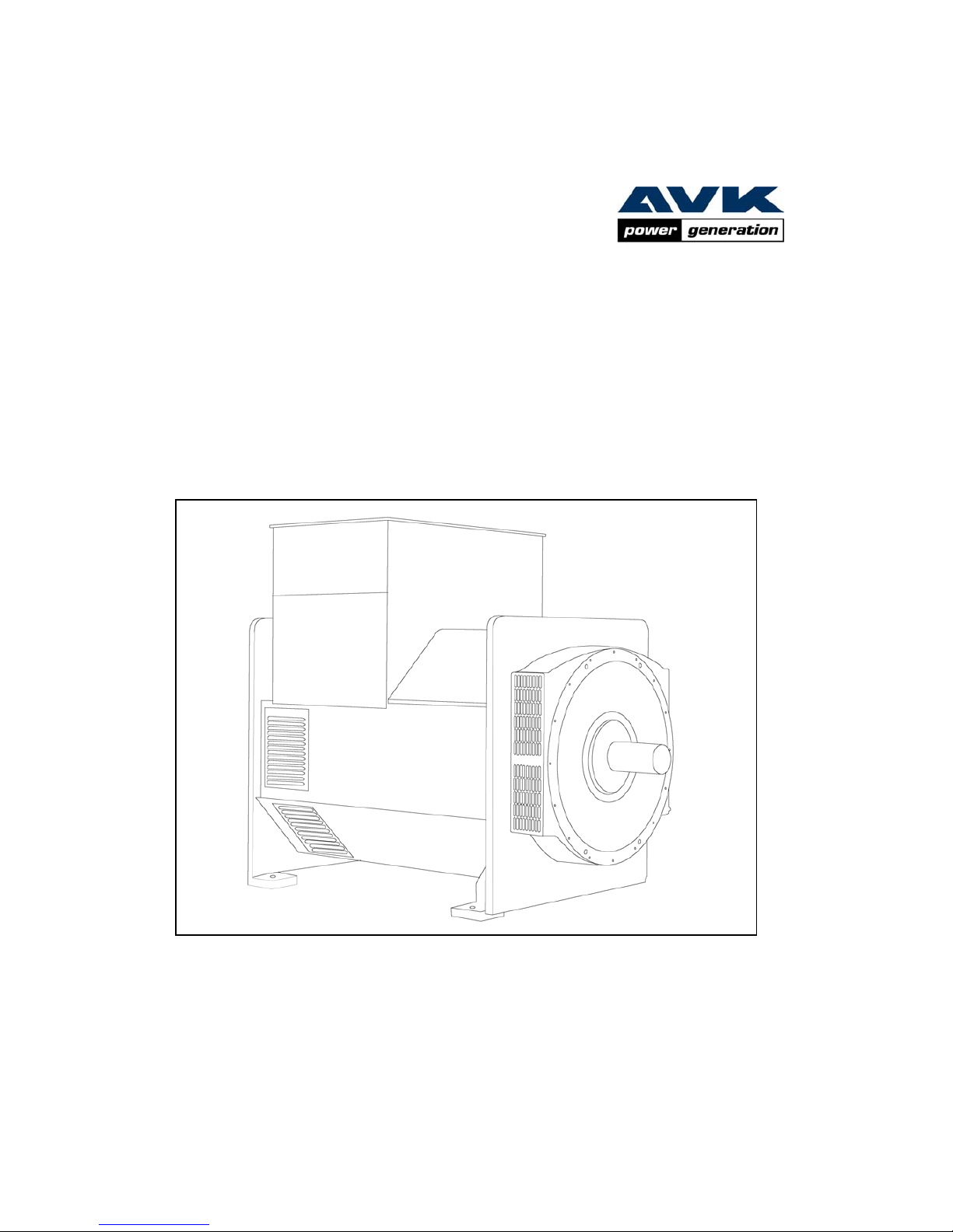
LVSI824, MVSI824, HVSI824, LVSM824 – Installation Manual
Page 2

0
SAFETY PRECAUTIONS
Before operating the generating set, read the generating set
operation manual and this generator manual and become
familiar with it and the equipment.
SAFE AND EFFICIENT OPERATION CAN ONLY BE
ACHIEVED IF THE EQUIPMENT IS CORRECTLY
OPERATED AND MAINTAINED.
Many accidents occur because of failure to follow
fundamental rules and precautions.
ELECTRICAL SHOCK CAN CAUSE SEVERE PERSONAL
INJURY OR DEATH.
Observe all WARNING/CAUTION notices.
• Ensure installation meets all applicable safety and local
electrical codes. Have all installations performed by a
qualified electrician.
• Do not operate the generator with protective covers,
access covers or terminal box covers removed.
• Disable engine starting circuits before carrying out
maintenance.
• Disable closing circuits and/or place warning notices on
any circuit breakers normally used for connection to the
mains or other generators, to avoid accidental closure.
Observe all IMPORTANT, CAUTION, WARNING, and
DANGER notices, defined as:
Important ! Important refers to hazard or unsafe
method or practice which can result in
product damage or related equipment
damage.
Caution!
Caution, refers to hazard or unsafe
method or practice which can result in
product damage or injury to personnel.
Warning!
Warning, refers to a hazard or unsafe
method or practice that can result
severe injury to personnel, possibly
death.
Danger !
Danger, refers to immediate hazards
which will result in severe injury or
death to personnel.
Due to our policy of continuous improvement, details in this manual which were
correct at time of printing, may now be due for amendment. Information
included must therefore not be regarded as binding.
Page 3

1
FOREWORD
The function of this book is to provide the user of the Stamford
generator with an understanding of the principles of operation,
the criteria for which the generator has been designed, and the
installation and maintenance procedures. Specific areas where
the lack of care or use of incorrect procedures could lead to
equipment damage and/or personal injury are highlighted, with
WARNING and/or CAUTION notes. It is important that the
contents of this book are read and understood before
proceeding to fit or use the generator.
The Service, Sales and technical staff of Newage International
are always ready to assist. Reference to the company for
advice is welcomed.
Warning!
Incorrect installation, operation,
servicing or replacement of parts
can result in severe personal injury
or death, and/or equipment damage.
Service personnel must be qualified
to perform electrical and mechanical
service.
EC DECLARATION OF INCORPORATION
All Stamford generators are supplied with a declaration of
incorporation for the relevant EC legislation, typically in the
form of a label as below.
Fig.1
Under the EC Machinery Directive section 1.7.4. It is the
responsibility of the generator set builder to ensure the
generator serial and identity numbers are clearly displayed in
the white box provided on the front cover of this book.
ELECTROMAGNETIC COMPATIBILITY
Additional Information
European Union
Council Directive 89/336/EEC
For installations within the European Union, electrical
products must meet the requirements of the above
directive, and Newage ac generators are supplied on the
basis that:
• They are to be used for power-generation or related
function.
• They are to be applied in one of the following
environments:
Portable (enclosed - temporary site supply)
Containerised (temporary or permanent site supply)
Ship-borne below decks (marine auxiliary power)
Commercial vehicle (road transport / refrigeration
etc) Rail transport (auxiliary power)
Industrial vehicle (earthmoving, cranes etc)
Fixed installation (industrial - factory / process plant)
Fixed installation (residential, commercial and light
industrial - home / office / health)
Energy management (Combined heat and power
and/or peak lopping)
Alternative energy schemes.
• The standard generators are designed to meet the
‘industrial’ emissions and immunity standards. Where
the generator is required to meet the residential,
commercial and light industrial emissions and immunity
standards reference should be made to Newage
document reference N4/X/011, as additional equipment
may be required.
• The installation earth scheme involves connection of
the generator frame to the site protective earth
conductor using a minimum practical lead length.
• Maintenance and servicing with anything other than
factory supplied or authorised parts will invalidate any
Newage liability for EMC compliance.
• Installation, maintenance and servicing is carried out by
adequately trained personnel fully aware of the
requirements of the relevant EC directives
EC DECLARATION OF INCORPORATION
IN ACCORDANCE WITH THE SUPPLY OF MACHINERY (SAFETY) REGULATIONS 1992
AND THE SUPPLY OF MACHINERY (SAFETY) (AMENDMENT) REGULATIONS 1994
IMPLEMENTING THE EC MACHINERY DIRECTIVE 89/392/EEC AS AMENDED BY 91/368/EEC.
THIS WAS
MANUFACTURED BY OR ON BEHALF OF
BARNACK ROAD STAMFORD LINCOLNSHIRE ENGLAND.
THIS COMPONENT MACHINERY MUST NOT BE PUT INTO SERVICE UNTIL THE
MACHINERY INTO WHICH IT IS TO BE INCORPORATED HAS BEEN DECLARED IN
CONFORMITY WITH THE PROVISIONS OF THE SUPPLY OF MACHINERY (SAFETY)
REGULATIONS 1995/MACHINERY DIRECTIVE.
STAMFORD A.C. GENERATOR
NEWAGE INTERNATIONAL LTD
FOR AND ON BEHALF OF NEWAGE INTERNATIONAL LIMITED
POSITION: TECHNICAL
SIGNATURE:
The EMC Directive 89/336/EEC
This Component Machinery shall not be used in the Residential, Commercial and
Light Industrial environment unless it also conforms to the relevant standard
(EN 50081 - 1) REFER TO FACTORY FOR DETAILS
ii) The Low Voltage Directive 73/23/EEC as amended by 93/68/EEC
WARNING!
THIS COMPONENT MACHINERY CARRIES THE CE MARK FOR COMPLIANCE W ITH THE STATUTORY
REQUIREMENTS FOR THE IMPLEMENTATION OF THE FOLLOWING DIRECTIVES
DIRECTOR
Page 4

2
CONTENTS
SAFETY PRECAUTIONS IFC
FOREWORD 1
CONTENTS 2
SECTION 1 INTRODUCTION 3
1.1 LV INTRODUCTION 3
1.1 MV INTRODUCTION 3
1.1 HV INTRODUCTION 3
1.2 DESIGNATION 3
1.3 SERIAL NUMBER LOCATION 3
1.4 RATING PLATE 3
1.5 BEARING GREASE INFORMATION 3
SECTION 2 PRINCIPLE OF OPERATION 4
SECTION 3 APPLICATION OF THE GENERATOR 5
SECTION 4 INSTALLATION PART 1 7
4.1 LIFTING 7
4.2 ASSEMBLY TO ENGINE 7
4.2.2 TWO BEARING MACHINES 7
4.3 EARTHING 8
4.4 PRE-RUNNING CHECKS 8
4.4.1 INSULATION CHECKS 8
4.4.1.1 LV GENERATORS 8
4.4.1.2 MV GENERATORS 8
4.4.1.3 HV GENERATORS 8
4.4.2 DIRECTION OF ROTATION 8
4.4.3 VOLTAGE FREQUENCY 8
4.4.4 AVR SETTINGS 8
4.5 GENERATOR SET TESTING 9
4.5.1 TEST METERING/CABLING 9
4.6 INITIAL START-UP 9
4.7 LOAD TESTING 10
4.7.1 AVR ADJUSTMENTS 10
4.7.2 UFRO (Under Frequency Roll Off) 10
4.7.3 OVER/V (Over Voltage) 10
4.7.4 EXC TRIP (Excitation Trip) 11
4.7.5 TRANSIENT LOAD SWITCHING ADJUSTMENTS 11
4.7.5.1 DIP 11
4.7.5.2 DWELL 11
4.8 ACCESSORIES 11
SECTION 5 INSTALLATION – PART 2 12
5.1 GENERAL 12
5.2 GLANDING 12
5.2.1 CONNECTIONS ON MV & HV GENERATORS 12
5.3 EARTHING 12
5.4 PROTECTION 13
5.5 COMMISSIONING 13
SECTION 6 ACCESSORIES 14
6.1 GENERAL 14
6.2 DROOP 14
6.2.1 SETTING PROCEDURE 15
6.3 OVER VOLTAGE DE-EXCITATION BREAKER 15
6.3.1 RESETTING THE BREAKER 15
6.4 FAULT LEVEL CURRENT LIMIT – TRANSFORMERS 15
6.4.1 SETTING PROCEDURE 15
6.5 POWER FACTOR CONTROLLER (PFC3) 16
Page 5

3
SECTION 1
INTRODUCTION
1.1 LV INTRODUCTION
The LV range of generators is of brushless rotating field
design, available up to 690V/50Hz (1500 rpm, 4 pole) and
600V/60Hz (1800 rpm, 4 pole) and built to meet BSEN
60034, BS5000 Part 3 and other appropriate international
standards.
All LV generators use a permanent magnet generator (PMG)
excitation system incorporating the MA325/7 AVR. Detailed
specification sheets are available on request.
1.1 MV INTRODUCTION
The MV range of generators is of brushless rotating field
design, available up to 3.3kV/50 Hz (1500 rpm, 4 pole) and
4.16kV/60Hz (1800 rpm, 4 pole) and built to meet BSEN
60034, BS5000 Part 3 and other appropriate international
standards.
All MV generators use a permanent magnet generator
(PMG) excitation system incorporating the MA325/7 AVR.
Detailed specification sheets are available on request.
1.1 HV INTRODUCTION
The HV range of generators is of brushless rotating field
design, available up to 11kV/50 Hz (1500 rpm, 4 pole) and
13.8kV/60Hz (1800 rpm, 4 pole) and built to meet BSEN
60034, BS5000 Part 3 and other appropriate international
standards.
All HV generators use a permanent magnet generator (PMG)
excitation system incorporating the MA325/7 AVR. Detailed
specification sheets are available on request.
1.2 DESIGNATION
The generator frame size is designated by a code as follows:
1.3 SERIAL NUMBER LOCATION
Each generator has its own unique serial number stamped
into the upper section of the frames drive-end end-plate.
Inside the terminal box two adhesive labels have been fixed,
each carrying the generators unique identity numbers.
One label has been fixed to the inside of the terminal box
sheet metal work, and the second label fixed to the saddle,
supporting the terminal box.
1.4 RATING PLATE
The generator has been supplied with a self adhesive Rating
Plate label to enable fitting after final assembly and painting.
It is intended that this label will be stuck to the outside of the
N.D.E. of the terminal box.
The surface in the area where a label is to be stuck must be
flat, clean and any paint finish be fully dry before attempting
to attach the label. Recommended method for attaching the
label is to peel and fold back sufficient of the backing paper
to expose some 20mm of label adhesive along the top edge.
Once this first section of the label has been carefully located
and stuck into position, the backing paper can be
progressively removed, as the label is pressed into position.
The adhesive will achieve a permanent bond in 24 hours.
1.5 BEARING GREASE INFORMATION
A self adhesive label will have been fixed to the end plate
above the bearing giving information about the bearing
grease type, re-lubrication frequency and quantities.
LVS I 82 4C
MVS I 8 2 4D
HVS I 8 2 4 E
GENERATOR TYPE
RANGE
STANDARD
INDUSTRIAL/MARINE
FRAME SIZE
MAJOR MOD STATUS
NUMBER OF POLES
CORE LENGTH
Page 6

4
SECTION 2
PRINCIPLE OF OPERATION
The permanent magnet generator provides power for
excitation of the exciter field via the AVR which is the
controlling device governing the level of excitation provided
to the exciter field. The AVR responds to a voltage sensing
signal derived, via the isolating transformer, from the main
stator winding. By controlling the low power of the exciter
field, control of the high power requirement of the main field
is achieved through the rectified output of the exciter
armature.
The simple control principle described above hides the
complexity of the electronic AVR which drives it. The AVR
senses true rms voltage on three phases ensuring close
regulation even with a generator output distorted by nonlinear load e.g. thyristor controlled DC drive. In addition it
detects engine speed and provides variable levels of voltage
fall off with speed, below a pre-selected speed (Hz) setting,
preventing over-excitation at low engine speeds and
softening the effect of load switching to relieve the burden on
the engine.
It also provides over-excitation protection during fault
conditions, and over-voltage protection, with provision for
operating an external circuit breaker, and additional
adjustable elements are incorporated to shape and optimise
the heavy load switching capability of the generating set, by
varying the generator performance during load switching to
match the engine performance.
The detailed function of the AVR circuits and their
adjustment are covered in the load testing section 4.7.
In addition the AVR incorporates circuits which, when used
in conjunction with accessories, can provide for parallel
operation either with 'droop' or 'astatic' control, short circuit
current limit, and VAr/PF control, during parallel operation.
Function and adjustment of the accessories which can be
fitted inside the generator terminal box are covered in the
accessories section of this book.
Separate instructions are provided with other accessories
available for control panel mounting.
Page 7
5
SECTION 3
APPLICATION OF THE GENERATOR
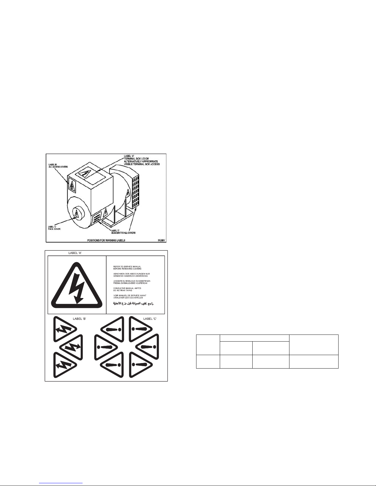
The generator is supplied as a component part for
installation in a generating set. It is not, therefore, practicable
to fit all the necessary warning/hazard labels during
generator manufacture. The additional labels required are
packaged with this Manual, together with a drawing
identifying their locations. (See below).
Information labels regarding bearing type, bearing grease,
and re-lubrication information have been fitted to each end
plate adjacent to bearing.
It is the responsibility of the generating set manufacturer to
ensure that the correct labels are fitted, and are clearly
visible.
The ambient conditions in which a generator is operated or
stored should be fully understood, to ensure the generator is
maintained in a fully serviceable condition. Areas for
consideration include temperature, humidity and even
vibration levels.
Temperatures should be stable, but if combined with high
humidity levels, anti-condensation heaters should be
connected to a suitable single phase mains supply. Within
the generator's storage or installed area, thermostatic control
of space heaters will be of considerable assistance.
If the generator is subjected to conditions which result in
condensation forming within the generator, steps must be
taken to ventilate and heat the generator. The winding
insulation resistance must be measured and be above the
minimum values stated in section 4.4.1.1 of this book before
the generator is put into service.
Subjecting stationary generators to vibration will cause
damage to the generator ball bearings, the process termed
brinelling.
The generators have been designed for use in a maximum
ambient temperature of 40°C. in accordance with B.S. 5000.
Ambients in excess of 40°C. can be tolerated with reduced
ratings - refer to the generator nameplate for rating and
ambient. In the event that the generator is required to
operate in an ambient in excess of the nameplate value or at
altitudes in excess of 1000 metres above sea level, refer to
the factory.
The generators are of air-ventilated screen protected dripproof design and are not suitable for mounting outdoors
unless adequately protected by the use of canopies. Anticondensation heaters are recommended during storage and
for standby duty to ensure winding insulation is maintained in
good condition.
When installed in a closed canopy it must be ensured that
the ambient temperature of the cooling air to the generator
does not exceed that for which the generator has been rated.
The canopy should be designed such that the engine air
intake to the canopy is separated from the generator intake,
particularly where the radiator cooling fan is required to draw
air into the canopy. In addition the generator air intake to the
canopy should be designed such that the ingress of moisture
is prohibited, preferably by use of a two stage filter.
The air intake/outlet must be suitable for the air flow given in
the following table with additional pressure drops less than or
equal to those given below:
Air Flow
Frame
50Hz 60Hz
Additional
(intake/outlet)
Pressure Drop
8
4.1m3/sec
(8680cfm)
4.8m3/sec
(10170cfm)
6mm water gauge
Important ! Reduction in cooling air flow or
inadequate protection to the
generator can result in damage
and/or failure of windings.
Dynamic balancing of the generator rotor assembly has been
carried out during manufacture in accordance with BS 6861
Part 1 Grade 2.5 to ensure vibration limits of the generator
are in accordance with BS 4999 Part 142.
Page 8

6
The main vibration frequencies produced by the generator
are as follows:-
4 pole 1500 rpm 25 Hz
4 pole 1800 rpm 30 Hz
However, vibrations induced by the engine are complex and
contain frequencies of 1.5, 3, 5 or more times the
fundamental frequency of vibration. These induced vibrations
can result in generator vibration levels higher than those
derived from the generator itself. It is the responsibility of the
generating set designer to ensure that the alignment and
stiffness of the bedplate and mountings are such that the
vibration limits of B.S. 5000 Part 3 are not exceeded.
In standby applications where the running time is limited and
reduced life expectancy is accepted, higher levels than
specified in BS5000 can be tolerated, up to a maximum of
18mm/sec.
Two bearing generators require a substantial bedplate with
engine/generator mounting pads to ensure a good base for
accurate alignment. Close coupling of engine to generator
can increase the overall rigidity of the set. For the purposes
of establishing set design the bending moment at the engine
flywheel housing to generator adaptor interface should not
exceed 275 kgm (2000 ft lbs) . A flexible coupling, designed
to suit the specific engine/generator combination, is
recommended to minimise torsional effects.
Alignment of single bearing generators is critical and
vibration can occur due to the flexing of the flanges between
the engine and generator. As far as the generator is
concerned the maximum bending moment at this
point must not exceed 275 kgm
(2000 ft lbs).
Single bearing generators require a substantial bedplate with
engine/generator mounting pads to ensure a good base for
accurate alignment.
The maximum bending moment of the engine flange must be
checked with the engine manufacturer.
Torsional vibrations occur in all engine-driven shaft systems
and may be of a magnitude to cause damage at certain
critical speeds. It is therefore necessary to consider the
torsional vibration effect on the generator shaft and
couplings.
It is the responsibility of the generator set manufacturer to
ensure compatibility, and for this purpose drawings showing
the shaft dimensions and rotor inertias are available for
customers to forward to the engine supplier. In the case of
single bearing generators coupling details are included.
Important ! Torsional incompatibility and/or
excessive vibration levels can cause
damage or failure of generator and/or
engine components.
The standard build terminal box arrangement is for cable
entry into the right hand side of the terminal box when
viewed from generator N. D. E.
Cable entry from the left hand side is possible if specified at
time of order.
The terminal box is constructed with a removable panel for
easy adaptation to suit specific glanding requirements.
Within the terminal box there are insulated terminals for line
and neutral connections and provision for earthing.
The neutral is NOT connected to the frame.
Caution! No earth connections are made on
the generator and reference to site
regulations for earthing must be
made. Incorrect earthing or
protection arrangements can result
in personal injury or death.
The main stator winding has six leads brought out to
terminals in the terminal box. The three leads brought to the
neutral terminal have been arranged to allow for the
provision of differential protection with the option of clamps
and mounting plates for specific current transformers
supplied by Newage International.
If it becomes necessary for customers to use current
transformers not of Newage supply, these should be fitted
by competent technicians with particular care being taken to
ensure the cables are positioned centrally within the current
transformer opening.
The generator AVR incorporates protection circuits which
operate on overload or fault conditions.
If a detected abnormal condition still exists after 8 seconds
the AVR de-excites the generator causing a collapse in
output voltage. This de-excitation may be as a result of an
electronic solid state protection circuit, or the AVR tripping
the excitation circuit breaker, if fitted, which would be
located adjacent to the AVR.
To reset the AVR trip circuits it is necessary to stop the
engine - generator. The AVR solid state trip circuits will
automatically reset after the generator has been stationary
for 3 seconds. The excitation trip circuit breaker needs to be
manually reset if fitted.
The system designer should ensure that these AVR
functions are compatible with the overall system protection.
Fault current curves (decrement curves), together with
generator reactance data, are available on request to assist
the system designer to select circuit breakers, calculate fault
currents and ensure discrimination within the load network.
This instruction book must be read before incorporation of
the generator into a generating set. Maintenance must be
carried out with the generating set out of service and
precautions taken to avoid accidental starting of the
generator set.
Warning !
Incorrect installation, service or
replacement of parts can result in
severe personal injury or death,
and/orequipment damage. Service
personnel must be qualified to
perform electrical and mechanical
service.
Page 9
7
SECTION 4
INSTALLATION - PART 1
4.1 LIFTING
Warning!
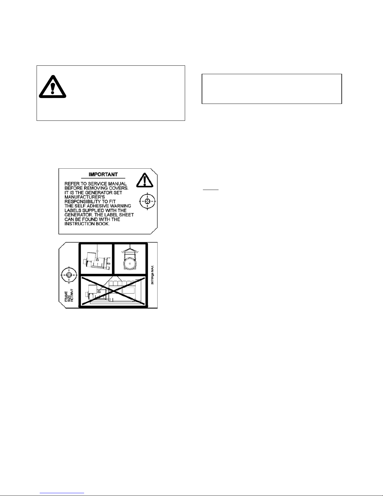
Four lifting lugs are provided for use with a shackle and pin
type lifting aid in conjunction with a spreader bar. Chains of
suitable length and lifting capacity must be used. Care is
therefore needed to avoid personal injury or equipment
damage. Correct lifting arrangement is shown on the label
attached to a lifting eye. A typical label is shown below.
Single bearing generators are supplied with the rotor
clamped to the stator frame with a transit strap to prevent
axial movement of the rotor and two shaft support brackets
have been fitted which support the rotor through the fan.
Once this strap is removed and the support bracket, to
couple the rotor to the engine, the rotor is free to move in the
frame, and care is needed during coupling and alignment to
ensure the frame is kept in the horizontal plane.
4.2 ASSEMBLY TO ENGINE
4.2.1 TWO BEARING MACHINES
A flexible coupling should be fitted and aligned in
accordance with the coupling manufacturer's instruction.
If a close coupling adaptor is used the alignment of
machined faces must be checked by offering the generator
up to the engine. Shim the generator feet if necessary.
Ensure adaptor guards are fitted after generator/engine
assembly is complete.
Open coupled sets require a suitable guard, to be provided
by the set builder.
Caution ! Incorrect guarding and/or generator
alignment can result in personal
Injury and/or equipment damage.
4.2.2 SINGLE BEARING MACHINES
4.2.2.1 INSTALLATION
All generators are transported from the factory with a shaftlocking strap fitted across the outside of the fan housing.
Premature removal of this strap will result in damage to the
rotor field excitor, fitted inboard of the non-drive end bearing.
So that the locking strap can be safely removed, two shaft
support brackets have been fitted which support the rotor
through the fan. It is inessential that that the support strip is
removed before the machine is run.
Before removing the strap and support brackets the
following steps must be followed:
1.
Once the Alternator is on site and positioned closely to
its final position, remove the shaft locking strap fitted
across the front of the shaft.
2. Couple the alternator to the engine. Note - the rotor
support brackets have not been designed so that the
alternator can not be barred over. The engine should be
bared over instead.
3. It is only safe to remove the support brackets when all
the engine/alternator-coupling bolts have been fully
tightened. This done by removing the bolt in each
support bracket and pulling it forward to clear the fan.
Finally withdraw it through the side opening.
4.2.2.2 ALIGNMENT
Alignment of single bearing generators is critical. If
necessary shim the generator feet to ensure alignment of the
machined surfaces.
The sequence of assembly to the engine should generally be
as follows:
1. On the engine check the distance from the coupling
mating face on the flywheel to the flywheel housing
mating face. This should be within 0.5mm of nominal
dimension. This is necessary to ensure that a thrust is
not applied to the AC generator bearing or engine
bearing.
2. Check that the bolts securing the flexible plates
to the Coupling hub are tight and locked into position.
For tightening torque refer to section 7 table H.
3. Remove covers from the drive end of the generator to
gain access to coupling and adaptor bolts.
4. Check that coupling discs are concentric with adaptor
spigot. This can be adjusted by the use of tapered
wedges between the fan and adaptor.
Alternatively the rotor can be suspended by means of
a rope sling through the adaptor opening.
Incorrect lifting of inadequate lifting
capacity can result in severe personal
injury of equipment damage. Lifting
capacity required for complete generator
is 7 tonnes. See data sheets for weights
of individual lifts. Generator lifting lugs
should not be used for lifting the complete
generating set.
Page 10

8
5. Offer the AC generator to engine and engage both
coupling discs and housing spigots at the same time,
finally pulling home by using the housing and
coupling bolts. Use heavy gauge washers between
bolt and head and discs on disc to flywheel bolts.
6. Tighten coupling disc to flywheel bolts. Refer to
engine manual for torque setting of disc to flywheel
bolts.
7. Remove wooden wedges.
8. Replace covers. Check for excessive vibration at the
time of initial run-up.
Important! Incorrect guarding and/or generator
alignment can result in personal injury
and/or equipment damage.
4.3 EARTHING
The generator frame should be solidly bonded to the
generating set bedplate. If antivibration mounts are fitted
between the generator frame and its bedplate a suitably
rated earth conductor (normally one half of the cross
sectional area of the main line cables) should bridge across
the antivibration mount.
4.4 PRE-RUNNING CHECKS
Caution! Refer to local regulations to ensure that
the correct earthing procedure has been
followed.
4.4.1 INSULATION CHECKS
Before starting the generating set after completing assembly,
test the insulation resistance of the main stator windings.
It should be noted that as winding temperature increases
values of insulation resistance will significantly reduce.
Therefore true values of insulation resistance should be
established with windings at ambient temperatures.
Caution! The AVR should be disconnected, and
the resistance temperature detector.
(RTD) leads grounded, during the test.
4.4.1.1 LV GENERATORS
A 500V Megger or similar instrument should be used.
Disconnect any earthing conductor connected between
neutral and earth and megger an output lead terminal U,V or
W to earth. The insulation resistance reading should be in
excess of 5MΩ to earth. Should the insulation resistance be
less than 5MΩ the winding must be dried out as detailed in
the Service and Maintenance Section of this Manual.
4.4.1.2 MV GENERATORS
A 2500V motorised Megger or similar instrument should be
used. Separate the three neutral leads, ground V and W
leads and megger U to ground. Repeat for V phase with U
and W grounded and W phase with U and V grounded.
The insulation resistance should not be less than 50MΩ and
the polarisation index should be in the order of 2 or greater
at 20°C.
If these values cannot be achieved the winding should be
dried out as detailed in the Service and Maintenance section
of this manual.
Danger!
4.4.1.3 HV GENERATORS
A 5000 V motorised Megger or similar instrument should be
used. Separate the three neutral leads, ground V and W
leads and megger U to ground. Repeat for V phase with U
and W grounded and W phase with U and V grounded.
The insulation resistance should not be less than 200 MΩ
and the polarisation index should be in the order of 2 or
greater at 20°C.
If these values cannot be achieved the winding should be
dried out as detailed in the Service and Maintenance section
of this manual.
Danger!
4.4.2 DIRECTION OF ROTATION
Standard machines are fitted with a backward inclined radial
bladed fan and therefore only suitable for running in one
direction of rotation. The generator is supplied to give a
phase sequence of U V W with the generator running
clockwise looking at the drive end (unless otherwise
specified at the time of ordering). If the generator phase
rotation has to be reversed after the generator has been
despatched apply to factory for appropriate wiring diagrams.
4.4.3 VOLTAGE AND FREQUENCY
Check that the voltage and frequency levels required for the
generating set application are within the range indicated on
the generator nameplate.
4.4.4 AVR SETTINGS
To adjust AVR settings remove the housing cover, and refer
to the label inside cover for guidance of adjustment
potentiometers and selection link location. The adjacent fig
1 also shows AVR layout.
Most of the AVR adjustments are factory set in positions
which will give satisfactory performance during initial running
tests. Subsequent adjustment may be required to achieve
optimum performance of the set under operating conditions.
Refer to section 4.7 for details.
Short stator terminals to earth
with an earthing rod after HV
testing, for at least 30 seconds
to discharge windings.
Short stator terminals to earth
with an earthing rod after HV
testing, for at least 30 seconds
to discharge windings.
Page 11

9
The following 'jumper' connections on the AVR should be
checked to ensure they are correctly selected for the
generating set application:
1) Frequency selection
Ufro switch position selected to suit operating frequency.
Initial Switch
Postion
4P/50Hz corresponds to1500 r.p.m. 4
4P/60Hz corresponds to1800 r.p.m. 5
Switch position to be optimised during commissioning.
2) Stability selection
Stability selection switch - select position 6.
4.5 GENERATOR SET TESTING
Fig. 1
4.5.1 TEST METERING/CABLING
Warning!
During testing it may be necessary to
remove covers to adjust controls
exposing 'live' terminals or components.
Only personnel qualified to perform
electrical service should carry out
testing and/or adjustments.
Connect any instrument wiring and cabling required for initial
test purposes with permanent or spring-clip type connectors.
Minimum instrumentation for testing should be line to line or
line to neutral voltmeter, Hz meter, load current metering and
kW meter. If reactive load is used a power factor meter is
desirable.
Important! When fitting power cables for load testing
purposes, ensure cable voltage rating is at
least equal to the generator rated voltage.
Support the cables to prevent side load
on the terminal.
The load cable termination should be placed on top of the
winding lead termination and clamped between the two nuts
provided, as shown below.
Caution!
MV/HV LOAD CABLE TERMINATION
Extending the load terminals by
means of an extension bar may
cause excessive side loads on the
ceramic terminal insulators and should
be avoided.
Caution!
Check that all wiring terminations
for internal or external wiring are
secure, and fit all terminal box
covers and guards. Failure to secure
wiring and/or covers may result in
personal injury and/or equipment failure.
4.6 INITIAL START-UP
Warning!
During testing it may be necessary to
remove covers to adjust controls
exposing 'LIVE' terminals or
components. Only personnel
qualified to perform electrical service
should carry out testing and/or
adjustments.
Refit all access covers after
adjustments are completed.
On completion of generating set assembly and before
starting the generating set ensure that all engine
manufacturer's pre-running procedures have been
completed, and that adjustment of the engine governor is
such that the generator will not be subjected to speeds in
excess of 125% of the rated speed.
Important! Overspeeding of the generator
during initial setting of the speed
governor can result in damage to
the generator rotating components.
A
2
A
utomatic Voltage Regulator
Dwell
NEWAGE
INTERNATIONAL
6S187S2 0v21A1
Volts UFROStab
Part No. E000-13270
E4E3
Ramp
UFRO Select 50/60Hz
Stability Select
Droop
Trim
Dip
Mode
Exc PWLO/V Hand
Page 12

10
In addition remove the AVR housing cover and turn "VOLTS"
control fully anti-clockwise.
Start the generating set and run on no-load at nominal
frequency. Slowly turn "VOLTS" control potentiometer
clockwise until rated voltage is reached. Refer to Fig. 1 for
potentiometer location.
Important! Do not increase the voltage above the
rated generator voltage shown on the
generator nameplate.
The "STABILITY" control potentiometer will have been preset and should normally not require adjustment, but should
this be required, usually identified by oscillation of the
voltmeter, refer to Fig. 1 for potentiometer location and
proceed as follows:-
1. Run the generating set on no-load and check that
speed is correct and stable.
2. Turn the "STABILITY" control potentiometer
clockwise,
then turn slowly anti-clockwise until the generator
voltage starts to become unstable.
The correct setting is slightly clockwise from this position (i.e.
where the machine volts are stable but close to the unstable
region).
4.7 LOAD TESTING
Warning!
During testing it may be necessary to
remove covers to adjust controls
exposing 'LIVE' terminals or
components. Only personnel qualified
to perform electrical service should
carry out testing and/or adjustments.
Refit all access covers after adjustments
are completed.
4.7.1 AVR ADJUSTMENTS
Refer to Fig. 1 for control potentiometer locations.
Having adjusted "VOLTS" and "STABILITY" during the initial
start-up procedure, the AVR control functions "UFRO", "OVER/V" a n d
"EXC. TRIP" should not normally need adjustment.
If however, poor voltage regulation on-load, or voltage
collapse is experienced, refer to the following paragraphs on
each function to a) check that the symptoms observed do
indicate adjustment is necessary, and b) to make the
adjustment correctly.
4.7.2 UFRO (Under Frequency Roll Off)
The AVR incorporates an underspeed protection circuit
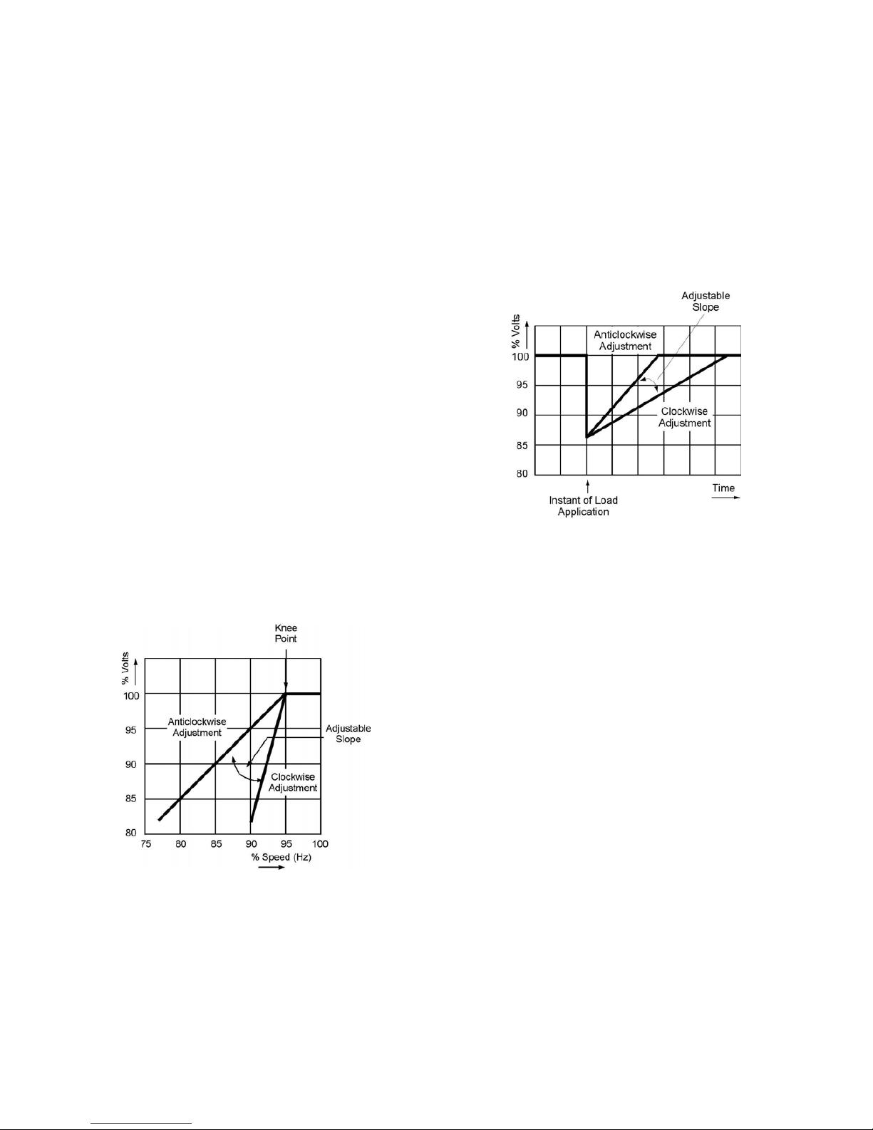
which gives a voltage/speed (Hz) characteristic as shown in
Fig. 2.
Fig. 2
The UFRO control potentiometer sets the "knee point".
Symptoms of incorrect setting are a) the light emitting diode
(LED) indicator, adjacent to the "UFRO" control
potentiometer, being permanently lit when the generator is
on load, and b) poor voltage regulation on load, i.e. operation
on the sloping part of the characteristic.
Important! If the LED is illuminated and no output
voltage is present, refer to EXC TRIP
and/or OVER/V sections below.
Clockwise adjustment lowers the frequency (speed) setting
of the "knee point" and extinguishes the LED. For optimum
setting the LED should illuminate as the frequency falls just
below nominal frequency, i.e. 47Hz on a 50Hz generator or
57Hz on a 60Hz generator.
4.7.3 OVER/V (Over Voltage)
Over voltage protection circuitry is included in the AVR to
remove generator excitation in the event of loss of AVR
sensing input or a short circuit of AVR power device. AVR
terminals E1, E0 are connected to the generator windings
independently of the AVR serving terminals.
A shunt trip circuit breaker is connected across AVR
terminals K1, K2 these connections under normal operation
being connected together.
If an over voltage condition is detected the AVR generates
an output pulse via terminals B0, B1 which activates the
shunt trip mechanism within the shunt trip circuit breaker.
This in turn opens circuits AVR terminals K1., K2., and deexcites the generator.
The generator must be stopped to reset an overvoltage trip.
Incorrect setting would cause the generator output voltage to
collapse at no-load or on removal of load, and the LED to be
illuminated,
The correct setting is 300V +/-5% across terminals E1, E0.
Clockwise adjustment of the “OVER/V” control potentiometer
will increase the voltage at which the circuit operates.
Page 13
11
4.7.4 EXC TRIP (Excitation Trip)
An AVR supplied from a permanent magnet generator
inherently delivers maximum excitation power on a line to
line or line to neutral short circuit. In order to protect the
generator windings the AVR incorporates an over excitation
circuit which detects high excitation and removes it after a
pre-determined time, i.e. 8-10 seconds.
Symptoms of incorrect setting are the generator output
collapses on load or small overload, and the LED is
permanently illuminated.
The correct setting is 70 volts +/-5% between terminals X
and XX.
4.7.5 TRANSIENT LOAD SWITCHING
ADJUSTMENTS
The additional function controls of "DIP" and "DWELL" are
provided to enable the load acceptance capability of the
generating set to be optimised. The overall generating set
performance depends upon the engine capability and
governor response, in conjunction with the generator
characteristics.
It is not possible to adjust the level of voltage dip or recovery
independently from the engine performance, and there will
always be a 'trade off' between frequency dip and voltage
dip.
4.7.5.1 DIP
The dip function control potentiometer adjusts the slope of
the voltage/speed (Hz) characteristic below the knee point as
shown in Fig.3.
Fig. 3
4.7.5.2 DWELL
The dwell function introduces a time delay between the
recovery of voltage and recovery of speed.
The purpose of the time delay is to reduce the generator kW
below the available engine kW during the recovery period,
thus allowing an improved speed recovery.
Again this control is only functional below the "knee point",
i.e. if the speed stays above the knee point during load
switching there is no effect from the "DWELL" function
setting.
Clockwise adjustment gives increased recovery time.
Fig. 4 shown below, is a representation only, since it is
impossible to show the combined effects of voltage regulator
and engine governor performance.
Fig. 4
4.8 ACCESSORIES
Refer to the "ACCESSORIES" Section of this Manual for
setting up procedures related to generator mounted
accessories.
If there are accessories for control panel mounting supplied
with the generator refer to the specific accessory fitting
procedures inserted inside the back cover of this book.
Replace AVR access cover after all adjustments are
completed.
Page 14

12
SECTION 5
INSTALLATION - PART 2
5.1 GENERAL
The extent of site installation will depend upon the generating set
build, e.g. if the generator is installed in a canopied set with integral
switchboards and circuit breaker, on site installation will be limited
to connecting up the site load to the generating set output
terminals. In this case reference should be made to the generating
set manufacturer's instruction book and any pertinent local
regulations.
If the generator has been installed on a set without switchboard or
circuit breaker the following points relating to connecting up the
generator should be noted.
5.2 GLANDING
The standard build terminal box arrangement is for cable entry into
the right hand side of the terminal box when viewed from generator
N.D.E. with removable panel for easy adaptation to suit specific
glanding requirements.
Incoming cables should be supported from either below or above
the box level and at a sufficient distance from the centre line of the
generating set so as to avoid a tight radius at the point of entry into
the terminal box panel, and allow movement of the generator set
on its anti-vibration mountings without excessive stress on the
cable.
In addition the cable should be clamped at the gland so that forces
on the cable due to set movement cannot be transmitted to the
insulated terminals in the terminal box.
Before making final connections, test the insulation resistance of
the windings. The AVR should be disconnected during this test and
RTD leads grounded.
For the MAIN STATOR WINDINGS the following type of megger or
similar instrument should be used.
LV Generators: 500V Motorised Instrument.
MV Generators: 2500V Motorised Instrument.
HV Generators: 5000V Motorised Instrument.
The measured Insulation Resistance should be above the value
stated in the table below.
GENERATOR TYPE
LV MV HV
5 Meg Ohms 50 Meg Ohms 200 Meg Ohms
If these values cannot be achieved the windings should be dried
out as detailed in the Service and Maintenance Section of this
manual.
A 1000V instrument is suitable for all other windings and a
minimum insulation resistance value of 1Meg Ohms should be
recorded.
5.2.1. CONNECTIONS ON MV & HV
GENERATORS
When making connections to the insulated terminals
the incoming cable termination should be placed on top
of the winding lead termination(s) and clamped
between the two nuts provided as shown in Fig. 5
Fig. 5
Caution! The load cables must not be
connected via any rigid right-angled
extension bar to the main terminals.
This will cause excessive side
loads on the ceramic insulations.
Important ! To avoid the possibility of swarf
entering any electrical components
in the terminal box, panels must be
removed for drilling.
5.3 EARTHING
The neutral of the generator is not bonded to the
generator frame as supplied from the factory. An earth
terminal is provided inside the terminal box adjacent to
the main terminals. Should it be required to operate
with the neutral earthed a substantial earth conductor
(normally equivalent to one half of the section of the
line conductors) must be connected between the
neutral and the earth terminal inside the terminal box.
The generator feet should be already bonded to the
generating set bedplate by the generating set builder,
and will normally be required to be connected to the
site earth system.
Caution! Reference to local electricity
regulations or safety rules should
be made to ensure correct
earthing procedures have been
followed.
Page 15
13
5.4 PROTECTION
Although the AVR incorporates certain protective elements
as already described, it is the responsibility of the end user
and his contractors/sub-contractors to ensure that the overall
system protection meets the needs of any inspectorate, local
electricity authority or safety rules, pertaining to the site
location.
High voltage transient surges generated by a switching
device or lightning strikes on overhead cables must be
prevented from reaching the generator terminals by the
fitting of correctly designed surge suppression devices.
These must be connected as close to the generator
terminals as practicable, and ideally consist of surge
arresters and surge capacitors.
A separate Newage publication, entitled Applications
Guidelines, covers this topic more fully and is available upon
request.
Where generators are connected to overhead transmission
lines either directly or via transformers, the overhead lines
should be fitted with surge arresters to reduce surge levels
on the more immediate generator protection. Overhead line
arresters should ideally be at a distance of 350m from the
generator.
To enable the system designer to achieve the necessary
protection and/or discrimination, fault current curves are
available on request from the factory, together with generator
reactance values to enable fault current calculations to be
made.
On LV generators the star point busbars arrangement allows
for the fitting of differential protection current transformers.
Provision has been made for an earth leakage detection
current transformer which is positioned between the star
point and neutral terminal.
On MV and HV generators the main stator winding has six
leads brought out to terminals in the terminal box. The three
leads brought to the neutral terminal have been arranged to
allow for the provision of differential protection with the
option of clamps and mounting plates for specific current
transformers supplied by Newage International.
If it becomes necessary for customers to use current
transformers not of Newage supply, these should be fitted in
an engineered manner with particular care being taken to
ensure the cables are positioned centrally within the current
transformer opening.
Generator output terminals can be offered in an arrangement
to suit the fitting of specific DIFFERENTIAL PROTECTION
current transformers supplied by Newage International. This
requirement should be specified at time of order.
Warning!
Incorrect installation and/or protective
Systems can result in personal injury
and/or equipment damage.
Installers must be qualified to perform
electrical installation work.
5.5 COMMISSIONING
Ensure that all external cabling is correct and that all the
generating set manufacturer's pre-running checks have been
carried out before starting the set.
The generator AVR controls will have been adjusted during
the generating set manufacturer's tests and should normally
not require further adjustment.
Should malfunction occur during commissioning refer to
Service and Maintenance section 'Fault Finding' procedure.
Page 16

14
SECTION 6
ACCESSORIES
6.1 GENERAL
Generator control accessories may be fitted, as an option. If
fitted at the time of supply, the wiring diagram(s) in the back
of this book shows the connections. When the options are
supplied separately, fitting instructions are provided with the
accessory.
Available accessories for generator mounting are as follows:
Quadrature droop current transformer;
VAr/PF controller and associate current transformers;
Fault level limiting current transformers.
There are two terminal box mounted accessories, which
relate to parallel operation i.e. DROOP and VAr/PF
controller. (See Paragraph 6.2 and 6.5 respectively).
Understanding of the following notes on parallel operation is
essential before attempting the fitting or setting of either
accessory.
When operating in parallel with other generators or the
mains, it is essential that the phase sequence of the
incoming generator matches that of the busbar and also that
all of the following conditions are met before the circuit
breaker of the incoming generator is closed on to the busbar
(or operational generator).
1. Frequency must match within close limits.
2. Voltages must match within close limits.
3. Phase angle of voltages must match within close
limits.
A variety of techniques, varying from simple synchronising
lamps to fully automatic synchronisers, can be used to
ensure these conditions are met.
Important ! Failure to meet conditions 1, 2, and 3
when closing the circuit breaker, will
generate excessive mechanical and
electrical stresses, resulting in
equipment damage.
Once connected in parallel a minimum instrumentation level
per generator of voltmeter, ammeter, wattmeter (measuring
total power per generator), and frequency meter is required
in order to adjust the engine and generator controls to share
kW in relation to engine ratings and kVAr in relation to
generator ratings.
It is important to recognise that:
1. True kW are derived from the engine, and speed
governor characteristics determine the kW sharing
between sets
and
2. kVAr are derived from the generator, and excitation
control characteristics determine the kVAr sharing.
Reference should be made to the generating set
manufacturer's instructions for setting the governor controls.
6.2 DROOP
The most commonly used method of kVAr sharing is to
create a generator voltage characteristic which falls with
decreasing power factor (increasing kVAr). This is achieved
with a current transformer (CT) which provides a signal
dependent on current phase angle (i.e. power factor) to the
AVR.
Note:if 'current limit' transformers are fitted the "W' phase CT
provides both droop and current limit.
The current transformer has a burden resistor on the AVR
board, and a percentage of the burden resistor voltage is
summed into the AVR circuit. Increasing droop is obtained
by turning the "DROOP" control potentiometer clockwise.
Fig. 6 indicates the effect of droop in a simple two generator
system.
Generally 5% droop at full load current zero pf is sufficient to
ensure kVAr sharing.
Fig. 6
Page 17
15
If the droop accessory has been supplied with the generator
it will have been tested to ensure correct polarity and set to a
nominal level of droop. The final level of droop will be set
during generating set commissioning.
6.2.1 SETTING PROCEDURE
Depending upon available load the following settings should
be used - all are based on rated current level.
0.8pf LOAD (at full load current) SET DROOP TO 3%
Zero pf LOAD (at full load current) SET DROOP TO 5%
Setting the droop with low power factor load is the most
accurate.
Run each generator as a single unit at rated frequency or
rated frequency + 4% depending upon type of governor and
nominal voltage. Apply available load to rated current of the
generator. Adjust 'DROOP' control to give droop in line with
above table. Clockwise rotation increases amount of droop.
Note 1
Reverse polarity of the CT will raise the generator voltage
with load. The polarities S1-S2 shown on the wiring
diagrams are correct for clockwise rotation of the generator
looking at the drive end. Reversed rotation requires S1-S2 to
be reversed.
Note 2
The most important aspect is to set all generators equal. The
precise level of droop is less critical.
Note 3
A generator fitted with droop circuit, operated as a single unit
at rated load 0.8pf, is unable to maintain the usual +/-
½%
regulation.
A shorting switch can be connected across S1-S2 to restore
regulation for single running.
Important ! LOSS OF FUEL to an engine can cause
its generator to motor with consequent
damage to the generator windings.
Reverse power relays should be fitted to
trip main circuit breaker.
LOSS OF EXCITATION to the generator
can result in large current oscillations
with consequent damage to generator
windings. Excitation loss detection
equipment should be fitted to trip main
circuit breaker.
6.3 OVERVOLTAGE DE-EXCITATION BREAKER
This provides positive interruption of the excitation power in
the event of overvoltage due to loss of sensing or internal
AVR faults including the output power device.
Important ! When the circuit breaker is supplied
loose the AVR is fitted with a link on
terminals K1-K2 to enable operation of
AVR. When connecting the circuit
breaker this link must be removed.
6.3.1 RESETTING THE BREAKER
In the event of operation of the circuit breaker, indicated by
loss of generator output voltage, manual resetting is
required. When in the "tripped" state the circuit breaker
switch lever shows "OFF". To reset move the switch lever to
the position showing "ON".
Danger !
Terminals which are 'LIVE' with the
generating set running are exposed
when the AVR access cover is
removed. Resetting of the circuit
breaker must be carried out with he
generating set stationary, and engine
starting circuits disabled.
When fitted in the generator, access to the breaker is gained
by removal of the AVR access cover.
The circuit breaker is mounted on the AVR mounting bracket
either to the left or to the right of the AVR depending upon
AVR position. After resetting the circuit breaker replace the
AVR access cover before restarting the generating set.
Should resetting of the circuit breaker not restore the
generator to normal operation, refer to section 7, following
Fault Finding Procedure.
6.4 FAULT LEVEL CURRENT LIMIT - TRANSFORMERS
These accessories work in conjunction with the AVR circuits
to provide an adjustment to the level of current delivered into
a fault. One current transformer (CT) per phase is fitted to
provide current limiting on any line to line or line to neutral
fault.
Note: The W phase CT can also provide "DROOP". Refer to
6.2.1. for setting droop independent of current limit.
Adjustment means is provided with the "I/LIMIT" control
potentiometer on the AVR. Refer to Fig. 1 in section 4.5 for
location. If current limit transformers are supplied with the
generator the limit will be set in accordance with the level
specified at the time of order, and no further adjustment will
be necessary. However, should the level need to be
adjusted, refer to the setting procedure given in 6.4.1.
6.4.1 SETTING PROCEDURE
Run the generating set on no-load and check that engine
governor is set to control nominal speed.
Stop the generating set. Remove the wires to terminals K1,K2, and insulate the 'BARE ENDS' to make safe. Connect
a 5 amp 240V AC switch across the terminals K1-K2.
Turn the "I/LIMIT" control potentiometer fully anticlockwise.
Short circuit the stator winding with a bolted 3 phase short at
the main terminals. An AC current clip-on ammeter is
required to measure the winding lead current.
Page 18

16
Danger !
Danger, refers to immediate hazards
which will result in severe injury or
death to personnel.
With the switch across K1-K2 open start the generating set.
Close the switch across K1-K2 and turn the "I/LIMIT" control
potentiometer clockwise until required current level is
observed on the clip-on ammeter. As soon as correct setting
is achieved open the K1-K2 switch.
Should the current collapse during the setting procedure, the
internal protective circuits of the AVR will have operated. In
this event shut down the set and open the K1-K2 switch.
Restart the set and run for 10 minutes with K1-K2 switch
open, to cool the generator windings, before attempting to
resume the setting procedure.
Important ! Failure to carry out the correct COOLING
procedure may cause overheating and
consequent damage to the generator
windings.
6.5 POWER FACTOR CONTROLLER (PFC3)
This accessory is primarily designed for those generator
applications where operation in parallel with the mains
supply is required.
Protection against loss of mains voltage or generator
excitation is not included in the unit and the system designer
must incorporate suitable protection.
The electronic control unit requires both droop and kVAr
current transformers. When supplied with the generator,
wiring diagrams inside the back cover of this manual show
the connections and the additional instruction leaflet
provided gives details of setting procedures for the power
factor controller (PFC3).
The unit monitors the power factor of the generator current
and adjusts excitation to maintain the power factor constant.
This mode can also be used to control the power factor of
the mains if the point of current monitoring is moved to the
mains cables. Refer to the factory for appropriate details.
It is also possible to operate the unit to control kVAr of the
generator if required. Refer to the factory for appropriate
details.
Page 19

17
A.C. GENERATOR WARRANTY
WARRANTY PERIOD
A.C. Generators
In respect of a.c. generators the Warranty Period is eighteen months from
the date when the goods have been notified as ready for despatch by N.I.
or twelve months from the date of first commissioning (whichever is the
shorter period).
DEFECTS AFTER DELIVERY
We will make good by repair or, at our option, by the supply of a
replacement, any fault which under proper use appears in the goods within
the period specified on Clause 12, and is found on examination by us to be
solely due to defective material and workmanship; provided that the
defective part is promptly returned, carriage paid, with all identification
numbers and marks intact, or our works or, if appropriate to the Dealer who
supplied the goods.
Any part repaired or replaced, under warranty, will be returned by N.I. free
of harge (via sea freight if outside the UK).
We shall not be liable for any expenses which may be incurred in removing
or replacing any part sent to us for inspection or in fitting any replacement
supplied by us. We shall be under no liability for defects in any goods
which have not been properly installed in accordance with N.I.
recommended installation practices as detailed in the publications 'N.I.
Installation, Service and Maintenance Manual' and 'N.I. Application
Guidelines', or which have been improperly stored or which have been
repaired, adjusted or altered by any person except ourselves or our
authorised agents, or in any second-hand goods, proprietary articles or
goods not of our own manufacture although supplied by us, such articles
and goods being covered by the warranty (if any) given by the separate
manufacturers.
Any claim under this clause must contain fully particulars of the alleged
defect, the description of the goods, the date of purchase, and the name
and address of the Vendor, the Serial Number (as shown on the
manufacturers identification plate) or for Spares the order reference under
which the goods were supplied.
Our judgement in all cases of claims shall be final and conclusive and the
claimant shall accept our decision on all questions as to defects and the
exchange of a part or parts.
Our liability shall be fully discharged by either repair or replacement as
above, and in any event shall not exceed the current list price of the
defective goods.
Our liability under this clause shall be in lieu of any warranty or condition
implied by law as to the quality or fitness for any particular purpose of the
goods, and save as expressly provided in this clause we shall not be under
any liability, whether in contract, tort or otherwise, in respect of defects in
goods delivered or for any injury, damages or loss resulting from such
defects or from any work undone in connection therewith.
MACHINE SERIAL NUMBER
Page 20

18
2
2
3
4
5
6
7
8
9
10
REGISTERED OFFICE AND ADDRESS
NEWAGE INTERNATIONAL LIMITED, PO BOX 17, BARNACK ROAD, STAMFORD
LINCOLNSHIRE, PE9 2NB ENGLAND
Tel: +44 (0) 1780 484 000
Fax:+44 (0) 1780 484 100
Website: www.newage-avkseg.com
STAMFORD POWER GENERATION WORLDWIDE
1
AUSTRALIA
NEWAGE ENGINEERS PTY. LIMITED
PO Box 6027,
Baulkham Hills Business Centre,
Baulkham Hills NSW 2153
Tel: (61) 2 9680 2299
Fax: (61) 2 9680 1545
6
JAPAN
NEWAGE INTERNATIONAL JAPAN
8-5- 302 Kashima
Hachioji-shi
Tokyo, 192-03
Telefon: (81) 426 77 2881
Fax (81) 426 77 2884
2
CHINA
WUXI NEWAGE ALTERNATORS
LIMITED
Plot 49-A, Xiang Jiang Road
Wuxi High – Technical Industrial
Dev.Zone
Wuxi, Jiangsu 214028
PR of China
Tel.: (86) 51 027 63313
Fax: (86) 51 052 17673
7
MEXICO
NEWAGE Mexico
Stamford Mexico S de RL de CV
Av. Circuito Mexico No. 185
Parque Industrial 3 Naciones
San Luis Potosi, SLP
C.P. 78395
Tel: (00) 48 26 84 00
Fax: (00) 48 26 84 05
3
GERMANY
AvK DEUTSCHLAND GmbH & Co. KG
Niederlassung Dreieich
Benzstrasse 47-49
63303 Dreieich
Tel: (49) 61 03 50 39 0
Fax: (49) 61 03 50 39 40
8
NORWAY
NEWAGE NORGE A/S
∅
kern Naeringspark, Kabeigt 5
Postboks 28,
∅
kern, 0508 Oslo
Tel: Oslo (47) 22 97 44 44
Fax: (47) 22 97 44 45
4
INDIA
C.G. NEWAGE ELECTRICAL LIMITED
C33 Midc,
Ahmednagar 414111,
Maharashtra
Tel: (91) 241 778 224
Fax: (91) 241 777 494
9
SINGAPORE
NEWAGE ASIA PACIFIC PTE LIMITED
10 Toh Guan Road #05-03
TT International Tradepark
Singapore 608838
Tel: (65) 794 3730
Fax: (65) 898 9065
5
ITALY
NEWAGE ITALIA SrI
Via Triboniano,
20156 Milan
Tel: (39) 02 380 00714
Fax: (39) 02 380 03664
'STAMFORD' is a registered trademark
of Newage International Ltd.
10
SPAIN
STAMFORD IBERICA SA
Poligono Industrial ''Los Linares“
Avda.de Fuenlabrada, 38
E-28970 HUMANES DE MADRID
Tel: (34) 91 498 2000
Fax : (34) 91 498 2124
© 2002 Newage International Ltd
Printed in England
TD_INSF8GB_02.06_02.GB
Page 21

Filename: english frame8installation.doc
Directory: F:\MARKETING LITERATURE\Manuals\Frame 8
manuals\Installation & Service & Maintenance Manuals\English\F8 manuals in WORD
Template: C:\Program Files\Microsoft Office\Templates\Normal.dot
Title: SAFETY PRECAUTIONS
Subject:
Author: Jane Lilley
Keywords:
Comments:
Creation Date: 27/06/02 11:37
Change Number: 14
Last Saved On: 01/07/02 10:03
Last Saved By: Anita Fountain
Total Editing Time: 28 Minutes
Last Printed On: 01/07/02 10:04
As of Last Complete Printing
Number of Pages: 20
Number of Words: 8,494 (approx.)
Number of Characters: 48,420 (approx.)
 Loading...