

Page 1
DSG/DIGDSG/DIG AlternatorsAlternators
Installation, Service and Maintenance
English
Original Instructions
03-2019 ING-WI-0395/A046V044 (Issue
7)
Page 2

Page 3

Table of Contents
1. FOREWORD............................................................................................................................. 1
1.1 General.............................................................................................................................. 1
1.2 The Manual........................................................................................................................ 1
1.3 Legal.................................................................................................................................. 1
2. SAFETY PRECAUTIONS ......................................................................................................... 3
2.1 Safety Information and Notices used in this Manual......................................................... 3
2.2 Skill Requirements of Personnel ....................................................................................... 3
2.3 Risk Assessment............................................................................................................... 3
2.4 Personal Protective Equipment (PPE) .............................................................................. 3
2.5 Grounding.......................................................................................................................... 4
2.6 Noise ................................................................................................................................. 4
2.7 Electrical Equipment.......................................................................................................... 4
2.7.1 Work on Electrical Equipment ................................................................................ 4
2.8 Lock Out/Tag Out .............................................................................................................. 5
2.9 Lifting ................................................................................................................................. 5
2.10 Safety Zones: Alternator Operating Areas (Alternators with Open-Circuit
Cooling).............................................................................................................................. 5
2.11 Safety Zones: Alternator Operating Areas (Alternators with Closed-Circuit
Cooling).............................................................................................................................. 6
2.12 Safety Information Signs ................................................................................................. 7
2.12.1 Hazard Warning Labels ........................................................................................ 7
2.13 Oils and Grease .............................................................................................................. 8
2.13.1 Solvents and Substances Containing Solvents.................................................... 8
2.14 General Guidance ........................................................................................................... 8
2.14.1 General Safety Instructions .................................................................................. 9
2.14.2 General Guidance for Use.................................................................................. 10
3. SAFETY DIRECTIVES AND STANDARDS ........................................................................... 13
3.1 Low Voltage Directive: Declaration of Conformity Drawing............................................. 13
3.2 Machinery Directive: Declaration of Incorporation........................................................... 15
4. INTRODUCTION .................................................................................................................... 19
4.1 Serial Number.................................................................................................................. 19
4.2 Rating Plate..................................................................................................................... 19
4.3 Important Remarks.......................................................................................................... 19
4.4 Liability, Warranty and Guarantee................................................................................... 20
4.5 Intended Use ................................................................................................................... 21
4.5.1 Operating Conditions............................................................................................ 21
4.6 Documentation ................................................................................................................ 22
4.6.1 Additional Information........................................................................................... 22
4.6.2 Information not included in the Documentation.................................................... 22
5. TRANSPORTATION, STORAGE AND CORROSION PROTECTION .................................. 23
5.1 Transportation and Packaging ........................................................................................ 23
5.1.1 General ................................................................................................................. 23
5.1.2 General Information for Anti-Friction Bearings ..................................................... 23
iING-WI-0395/A046V044 (Issue 7)
Page 4

Table of Contents 03-2019
5.1.3 General Information for Sleeve Bearings ............................................................. 23
5.1.4 General Information for Air-Water Coolers ........................................................... 23
5.1.5 Packaging ............................................................................................................. 23
5.1.6 During Transport (DSG 125, DSG 144, DIG 140/150/156/163/167).................... 23
5.1.7 During Transport (DIG 142).................................................................................. 25
5.1.8 During Transport (All DSG and DIG 110/120/130)............................................... 26
5.1.9 Unpacking Checks/Items supplied ....................................................................... 28
5.1.10 Inspection on Arrival ........................................................................................... 28
5.1.11 Inspection on Unpacking .................................................................................... 28
5.2 Storage ............................................................................................................................ 29
5.2.1 Storage in a Suitable Room (less than 6 Months)................................................ 29
5.2.2 Storage in a Suitable Room (longer than 6 Months) ............................................ 29
5.2.3 Storage in Unsuitable Conditions (less than 2 Months) ....................................... 30
5.2.4 Storage in Unsuitable Conditions (longer than 2 Months).................................... 30
5.3 Protect Against Corrosion ............................................................................................... 30
5.3.1 Bare Surfaces....................................................................................................... 30
5.3.2 Sleeve Bearings ................................................................................................... 31
5.3.3 Anti-Friction Bearings ........................................................................................... 31
5.3.4 Air-Air Cooler ........................................................................................................ 32
5.3.5 Air-Water Cooler................................................................................................... 32
5.3.6 Customer Connection Openings .......................................................................... 32
5.4 Remove Corrosion Protection ......................................................................................... 32
5.4.1 Anti-Friction Bearings ........................................................................................... 32
5.4.2 Sleeve Bearings ................................................................................................... 32
5.4.3 Cooler ................................................................................................................... 33
5.4.4 Condensed Water Drain ....................................................................................... 33
5.5 Oil Drain Points ............................................................................................................... 34
6. INSTALLATION AND ALIGNMENT........................................................................................ 35
6.1 General............................................................................................................................ 35
6.2 Preparation of the Alternator ........................................................................................... 35
6.2.1 Alternators with Anti-Friction Bearings ................................................................. 35
6.2.2 Alternators with Sleeve Bearings.......................................................................... 35
6.2.3 Recommendations for Coupling Assembly........................................................... 36
6.3 Mounting Design.............................................................................................................. 36
6.3.1 General ................................................................................................................. 36
6.3.2 Mounting Forces................................................................................................... 37
6.3.3 Mounting on Marine Applications ......................................................................... 37
6.3.4 Installation on Concrete Foundations................................................................... 38
6.3.5 Installation on Steel Foundation ........................................................................... 39
6.4 Align the Prime Mover and Alternator ............................................................................. 40
6.4.1 General ................................................................................................................. 40
6.4.2 Theory of Alignment ............................................................................................. 40
6.4.3 Compensate for Thermal Expansion.................................................................... 41
6.4.4 Assemble the Coupling Halves............................................................................. 42
6.4.5 Coarse Alignment ................................................................................................. 43
6.4.6 Final Alignment..................................................................................................... 43
6.5 Fit the Dowel Pins ........................................................................................................... 45
6.6 Measures for Delayed Commissioning............................................................................ 45
ii ING-WI-0395/A046V044 (Issue 7)
Page 5

Table of Contents03-2019
7. MECHANICAL AND ELECTRICAL CONNECTIONS............................................................. 47
7.1 General............................................................................................................................ 47
7.2 Mechanical Connections ................................................................................................. 47
7.2.1 Cooling Air Connections ....................................................................................... 47
7.2.2 Connect Cooling Water ........................................................................................ 48
7.2.3 Oil Supply for the Sleeve Bearings....................................................................... 48
7.3 Connect Vibration Sensors.............................................................................................. 49
7.3.1 Anti-Friction Bearings ........................................................................................... 49
7.3.2 Sleeve Bearings ................................................................................................... 49
7.4 Electrical Installation........................................................................................................ 49
7.4.1 General Information.............................................................................................. 49
7.4.2 Safety.................................................................................................................... 49
7.4.3 Moisture ................................................................................................................ 50
7.4.4 Insulation Resistance ........................................................................................... 50
7.4.5 Main Terminal Box................................................................................................ 51
7.4.6 Auxiliary Terminal Boxes ...................................................................................... 51
7.4.7 Isolation Distances for the Primary Line Connections.......................................... 51
7.4.8 Primary Line Cables ............................................................................................. 51
7.5 Criteria that Affect the Output Power .............................................................................. 54
7.5.1 Design Criteria...................................................................................................... 54
7.5.2 Effect of Coolant Temperature ............................................................................. 54
7.5.3 Effect of Installation Altitude ................................................................................. 55
7.5.4 Effect of Power Factor Cos Phi ............................................................................ 55
7.6 Electrical Behavior........................................................................................................... 56
7.6.1 Principle of Operation ........................................................................................... 56
7.6.2 Voltage Regulator................................................................................................. 56
7.6.3 Self-excitation, De-excitation ................................................................................ 57
7.6.4 Voltage and Frequency ........................................................................................ 57
7.6.5 Currents ................................................................................................................ 59
7.7 Parallel Operation............................................................................................................ 61
7.7.1 General ................................................................................................................. 61
7.7.2 Parallel Switching Conditions ............................................................................... 61
7.7.3 Island Parallel Operation ...................................................................................... 61
7.7.4 Operation in Parallel with the Line System .......................................................... 62
8. COMMISSIONING AND STARTING ...................................................................................... 63
8.1 General............................................................................................................................ 63
8.2 Check the Mechanical Installation................................................................................... 63
8.3 Check the Electrical Installation ...................................................................................... 63
8.4 Controller and Protective Equipment............................................................................... 63
8.4.1 General ................................................................................................................. 63
8.4.2 Stator Winding Temperature ................................................................................ 64
8.4.3 Maximum Temperature Setting ............................................................................ 64
8.4.4 Maximum Settings for the Stator Temperature .................................................... 64
8.4.5 Monitoring the Bearing Temperature.................................................................... 64
8.5 First Run.......................................................................................................................... 65
8.5.1 General ................................................................................................................. 65
8.5.2 Before Starting...................................................................................................... 66
8.5.3 Starting ................................................................................................................. 66
8.5.4 Direction of Rotation of the Alternator and External Motors................................. 66
iiiING-WI-0395/A046V044 (Issue 7)
Page 6

Table of Contents 03-2019
8.5.5 Ground Fault Monitoring....................................................................................... 66
8.6 Operate the Alternator for the First Time ........................................................................ 67
8.6.1 Monitoring during Operation ................................................................................. 67
8.7 Check the Alternator in Operation ................................................................................... 67
8.7.1 Bearings................................................................................................................ 68
8.7.2 Vibration................................................................................................................ 68
8.7.3 Temperature Level ............................................................................................... 68
8.7.4 Heat Exchanger.................................................................................................... 69
8.8 Shut Down the Alternator ................................................................................................ 69
9. OPERATION........................................................................................................................... 71
9.1 General............................................................................................................................ 71
9.2 Normal Operating Conditions .......................................................................................... 71
9.3 Number of Starts ............................................................................................................. 71
9.4 Monitoring........................................................................................................................ 71
9.4.1 Bearings................................................................................................................ 72
9.4.2 Vibration................................................................................................................ 72
9.4.3 Stator Temperatures............................................................................................. 72
9.4.4 Heat Exchangers .................................................................................................. 72
9.4.5 Slip Ring Units ...................................................................................................... 72
9.4.6 Documentation of Operation................................................................................. 72
9.5 Shutting Down ................................................................................................................. 72
9.6 Anti-Condensation Heaters ............................................................................................. 72
9.7 Flashover Pressure Protection ........................................................................................ 73
9.8 Firefighting and Extinguishing Agents............................................................................. 74
9.8.1 General ................................................................................................................. 74
9.8.2 Extinguishing Agents ............................................................................................ 74
9.8.3 Cleaning After Fire-fighting................................................................................... 75
10. SERVICE AND MAINTENANCE........................................................................................... 77
10.1 Preventive Servicing...................................................................................................... 77
10.2 Safety Precautions ........................................................................................................ 77
10.3 Recommended Servicing Schedule .............................................................................. 78
10.3.1 Alternator ............................................................................................................ 79
10.3.2 Main Electrical Connections ............................................................................... 80
10.3.3 Stator and Rotor ................................................................................................. 81
10.3.4 Accessories ........................................................................................................ 82
10.3.5 Slip Ring Units .................................................................................................... 83
10.3.6 Lubrication System and Anti-friction Bearings.................................................... 84
10.3.7 Lubrication System and Sleeve Bearings........................................................... 85
10.3.8 Cooling System .................................................................................................. 86
10.3.9 Safety.................................................................................................................. 86
10.4 Servicing - General Structure........................................................................................ 86
10.4.1 Strength of Screw Fasteners.............................................................................. 87
10.5 Vibration ........................................................................................................................ 89
10.5.1 Measuring Methods and Operating Conditions .................................................. 89
10.5.2 Definition in Accordance with ISO 10816-3........................................................ 90
10.5.3 Definition in Accordance with ISO 8528-9.......................................................... 91
10.5.4 Warning Values and Shutdown Values .............................................................. 91
10.6 Servicing the Bearings and the Lubrication System...................................................... 92
iv ING-WI-0395/A046V044 (Issue 7)
Page 7

Table of Contents03-2019
10.6.1 Sleeve Bearings ................................................................................................. 92
10.6.2 Anti-Friction Bearings ......................................................................................... 94
10.7 Alternators with Bearing Insulation................................................................................ 99
10.7.1 Bearing Insulation on Sleeve Bearings .............................................................. 99
10.7.2 Bearing Insulation on Anti-Friction Bearings ...................................................... 99
10.8 Service Windings........................................................................................................... 99
10.8.1 Safety Instructions for Servicing Windings ......................................................... 99
10.8.2 Scheduling the Servicing .................................................................................. 100
10.8.3 Correct Operating Temperature of Windings ................................................... 100
10.8.4 Insulation Resistance Test ............................................................................... 100
10.8.5 Insulation Resistance Measurement for Ancillary Equipment .......................... 102
10.8.6 The Polarization Index...................................................................................... 102
10.8.7 Servicing the Grounding Brushes..................................................................... 102
10.9 Servicing the Alternator Cooling.................................................................................. 104
10.9.1 Servicing Instructions for Alternators with Open-circuit Ventilation .................. 104
10.9.2 Service Instructions for Alternators with Air Filters........................................... 104
10.9.3 Servicing Instructions for Alternators with Heat Exchangers ........................... 105
10.10 Rectifier System ........................................................................................................ 106
10.10.1 Rectifier System for Alternators without Grid Code Compliance.................... 106
10.10.2 Rectifier System - Grid Code Compliance...................................................... 109
10.11 Repairs, Dismantling and Re-assembly .................................................................... 112
11. FAULT FINDING ................................................................................................................. 113
11.1 General Alternator ....................................................................................................... 114
11.2 Lubrication System and Anti-friction Bearings............................................................. 115
11.3 Lubrication System and Sleeve Bearings.................................................................... 116
11.4 Open Cooling System ................................................................................................. 117
11.5 Air-Air Cooling System ................................................................................................ 118
11.6 Air-Water Cooling System ........................................................................................... 119
11.7 Faults on the Brushes ................................................................................................ 120
11.8 Fault Finding Sleeve Bearings .................................................................................... 120
11.8.1 Oil Leaks on Sleeve Bearings .......................................................................... 120
11.8.2 Oil ..................................................................................................................... 121
11.8.3 Checking the Bearings ..................................................................................... 121
11.8.4 Check on the Oil Tank and the Oil Lines.......................................................... 121
11.8.5 Vibration and Oil ............................................................................................... 122
11.8.6 Check on Vibration ........................................................................................... 122
11.8.7 Hydrostatic System........................................................................................... 122
11.8.8 Air Pressure in the Bearing .............................................................................. 122
11.8.9 Air Pressure Outside the Bearing..................................................................... 122
11.9 Electrical Power, Excitation, Control and Protection ................................................... 124
11.9.1 Triggering the Protective System ..................................................................... 124
11.9.2 PT100/PT1000 Resistive Temperature Sensors.............................................. 124
11.10 Thermal Performance and Cooling System .............................................................. 125
12. SERVICE PARTS AND AFTER SALES SERVICE ............................................................ 127
12.1 Service Parts for Alternators ....................................................................................... 127
12.1.1 General Information on the Service Parts ........................................................ 127
12.2 Customer Service........................................................................................................ 127
12.2.1 Customer Service and Warranty ...................................................................... 128
vING-WI-0395/A046V044 (Issue 7)
Page 8

Table of Contents 03-2019
13. END OF LIFE DISPOSAL ................................................................................................... 129
13.1 Disposal....................................................................................................................... 129
13.2 Introduction.................................................................................................................. 129
13.3 Average Material Content............................................................................................ 129
13.4 Recycling Packaging Material ..................................................................................... 130
13.5 Dismantling the Alternator ........................................................................................... 130
13.6 Separation of the Different Materials........................................................................... 130
13.6.1 Stator, Bearing Housing, Covers and Fans...................................................... 130
13.6.2 Components with Electrical Insulation.............................................................. 131
13.6.3 Hazardous Waste ............................................................................................. 131
13.6.4 Residual Waste ................................................................................................ 131
vi ING-WI-0395/A046V044 (Issue 7)
Page 9

1 Foreword
1.1 General
This manual forms part of the items supplied and is an important technical guide to the intended use
of the alternator. It represents an essential source of information for the user and also for managers
for the prevention of injuries and damage to the alternator.
The alternator was manufactured by:
Cummins Generator Technologies
Bvd. Decebal 116A
Craiova, Dolj
200746 Romania
Tel: +40 351 443200
Fax: +40 351 443201
On the pages that follow the complete name of the company is replaced with the term
"manufacturer".
NOTICE
The alternator is the intellectual property of Cummins Generator Technologies. The general safety
regulations, the specific regulations for the place of use and the precautions described in this
document must be followed at all times.
1.2 The Manual
This manual contains guidance and instructions for the installation, servicing and maintenance of the
alternator.
Before operating the alternator, read this manual and make sure that all personnel who work on the
equipment have access to the manual and all additional documentation supplied with it. Misuse and
failure to follow the instructions, and the use of non-approved parts, may invalidate the product
warranty and lead to potential accidents.
This manual is an essential part of the alternator. Make sure that the manual is available to all users
throughout the life of the alternator.
The manual is written for skilled electrical and mechanical technicians and engineers, who have prior
knowledge and experience of generating equipment of this type. If in doubt, please seek expert advice
or contact your local Cummins Generator Technologies subsidiary.
Information in this manual was correct when published. It may be superseded due to our
policy of continuous improvement. Please visit www.stamford-avk.com for latest
documentation.
NOTICE
1.3 Legal
All rights to the alternator, the principle of the machine, the related drawings etc. lie with Cummins
Generator Technologies® and are subject to copyright law. Copying is only permitted with prior written
approval. © 2018, Cummins Inc. All Rights reserved.
1ING-WI-0395/A046V044 (Issue 7)
Page 10

1. Foreword 03-2019
This page is intentionally blank.
2 ING-WI-0395/A046V044 (Issue 7)
Page 11

2 Safety Precautions
2.1 Safety Information and Notices used in this Manual
Danger, Warning and Caution panels are used in this manual to describe the sources of hazards, their
consequences and how to avoid injury. Notice panels emphasize important or critical instructions.
DANGER
Danger indicates a hazardous situation which, if not avoided, WILL result in death or serious
injury.
WARNING
Warning indicates a hazardous situation which, if not avoided, COULD result in death or
serious injury.
CAUTION
Caution indicates a hazardous situation which, if not avoided, COULD result in minor or
moderate injury.
NOTICE
Notice refers to a method or practice which can result in product damage, or to draw
attention to additional information or explanations.
2.2 Skill Requirements of Personnel
Service and maintenance procedures must only be carried out by experienced and qualified
engineers, who are familiar with the procedures and the equipment.
2.3 Risk Assessment
A risk assessment has been performed on this product by Cummins, however a separate risk
assessment must be performed by the user/operating company to establish all personnel-related risks.
All affected users must be trained on the identified risks. Access to the Power Plant/Generator Set
during operation must be restricted to persons who have been trained on these risks.
2.4 Personal Protective Equipment (PPE)
All persons operating, servicing, maintaining or working in or with a power plant or a generator set
must wear appropriate Personal Protective Equipment (PPE)
Recommended PPE includes:
• Ear and Eye Protection
• Head and face protection
• Safety footwear
• Overalls that protect the lower arms and legs
3ING-WI-0395/A046V044 (Issue 7)
Page 12

2. Safety Precautions 03-2019
Ensure that all persons are fully aware of the emergency procedures in case of accidents.
2.5 Grounding
WARNING
High Voltage
Will shock, burn or can cause death.
Work on electrical systems must be done by an electrician or instructed persons under the
management and supervision of an electrician wearing suitable PPE.
Parts of the machine and system on which inspections, servicing and repair work are done must, if so
stipulated, be electrically isolated.
1. Test the electrically isolated parts for electrical isolation using a suitable voltage tester, then ground
and short-circuit and also isolate neighboring live parts.
2. In case of work on high-voltage assemblies, after electrically isolating connect the line cable to
ground and short-circuit the components, e.g. capacitors, using a grounding bar.
The alternator is permanently grounded.
2.6 Noise
CAUTION
Alternators in operation emit noise. Exposure to noise can cause hearing damage. Wear
appropriate ear protection at all times. Maximum A-weighted noise emissions may reach 110
dB(A). Contact the supplier for application-specific details.
2.7 Electrical Equipment
DANGER
Hazardous Voltage
Will shock, burn or cause death
All electrical equipment can be dangerous if not operated correctly. Always install, service
and maintain the alternator in accordance with this manual.
Work that requires access to electrical conductors must comply with all applicable local and national
electrical safety procedures for the voltages involved and any site specific rules. Always use genuine
branded replacement parts.
2.7.1 Work on Electrical Equipment
DANGER
Hazardous voltage.
Will shock burn or cause death.
The colors of electrical cables and connections comply with the applicable regulations (VDI).
If the operating organization has agreed different colors with the manufacturer, these colors
apply.
Before working on electrical equipment, the entire system must be electrically isolated and
grounded.
4 ING-WI-0395/A046V044 (Issue 7)
Page 13
2. Safety Precautions03-2019
DANGER
Hazardous voltage.
Will shock burn or cause death.
Faulty electrical components can be live and as a result life-threatening. Any defects found in
electrical systems, assemblies, equipment must be rectified without delay. If there is an acute
risk until rectified, the system or the assembly must not be used in the defective state.
WARNING
Magnetic field.
Alternator has a powerful magnetic field that can interfere with implanted medical devices
such as heart pacemakers.
Do not approach the alternator if you have an implanted medical device.
Work on electrical cables is to be done in accordance with local or national electrical safety
regulations applicable for the voltage as well as the safety regulations applicable on the site.
Each alternator is built in accordance with the applicable regulations. The electrical control system is
compliant with the VDE regulations, VBG 4 and EN 60204.
• Only use approved protective equipment
• In case of malfunctions in the supply of electrical power, immediately shut down the unit
(exception: if used as an emergency power alternator).
2.8 Lock Out/Tag Out
Risk of serious injury or death
Alternators can retain mechanical and electrical energy
Isolate the alternator from all sources of mechanical and electrical energy before starting
service or maintenance work. Adopt a suitable lock-out/tag out process.
2.9 Lifting
Improper lifting can cause serious injuries to persons or can cause death.
Do not use the alternator lifting points to lift the complete generator set (alternator coupled to
motive power source)
The lifting points provided are designed for lifting the alternator only.
Do not remove the lifting label attached to one of the lifting points.
WARNING
WARNING
2.10 Safety Zones: Alternator Operating Areas (Alternators with Open-Circuit Cooling)
Personnel, required to work in the alternator operating areas must be informed about the potential
risks and wear appropriate PPE.
In event of system malfunction, close proximity to areas of the alternator may present an elevated risk
of hazard exposure.
Make sure this consideration is captured in your risk assessment.
5ING-WI-0395/A046V044 (Issue 7)
Page 14

2. Safety Precautions 03-2019
DANGER
Flying debris
Exposure to mechanically driven release of particles from alternator in the area of air outlet in
horizontal direction +/- 90° in elevation and +/- 75° in axial direction. This also applies to all
directions on the open shaft end, commonly known as drive end. Avoid these areas while the
alternator is operating.
DANGER
Flying particles and fumes
Exposure to electrically driven release of particles and fumes from alternator:
This may be released from all ventilation openings, air intake and air outlet. This can be
released in all directions (360°) from any ventilation openings.
Avoid these areas while the alternator is operating.
DANGER
Electrical particles and fumes from terminal boxes
Exposure to electrical driven release of particles and fumes from alternator terminal boxes:
All main terminal box cable entrance ducts are equipped with an overpressure release flap to
discharge energy from the main terminal boxes in case of internal combustion.
Depending on the machine design, the pressure release flap can be located at different
positions and directions, according to the ordered cable entry direction.
It is important to identify the position of the pressure release flap and avoid it during
operation.
2.11 Safety Zones: Alternator Operating Areas (Alternators with Closed-Circuit Cooling)
Personnel, required to work in the alternator operating areas must be informed about the potential
risks and wear appropriate PPE.
In event of system malfunction, close proximity to areas of the alternator may present an elevated risk
of hazard exposure.
Make sure this consideration is captured in your risk assessment.
DANGER
Flying debris
Exposure to mechanical driven release of particles from alternator in the area of pressure
release flap in horizontal direction +/- 90° in elevation and +/- 75° in axial direction. This also
applies to all directions on the open shaft end, commonly known as the drive end. Avoid
these areas while the alternator is operating.
DANGER
Electrical particles and fumes from terminal boxes
Exposure to electrical driven release of particles and fumes from alternator terminal boxes:
All main terminal box cable entrance ducts are equipped with an overpressure release flap to
discharge energy from the main terminal boxes in case of internal combustion.
Depending on the machine design, the pressure release flap can be located at different
positions and directions, according to the ordered cable entry direction.
It is important to identify the position of the pressure release flap and avoid it during
operation.
6 ING-WI-0395/A046V044 (Issue 7)
Page 15
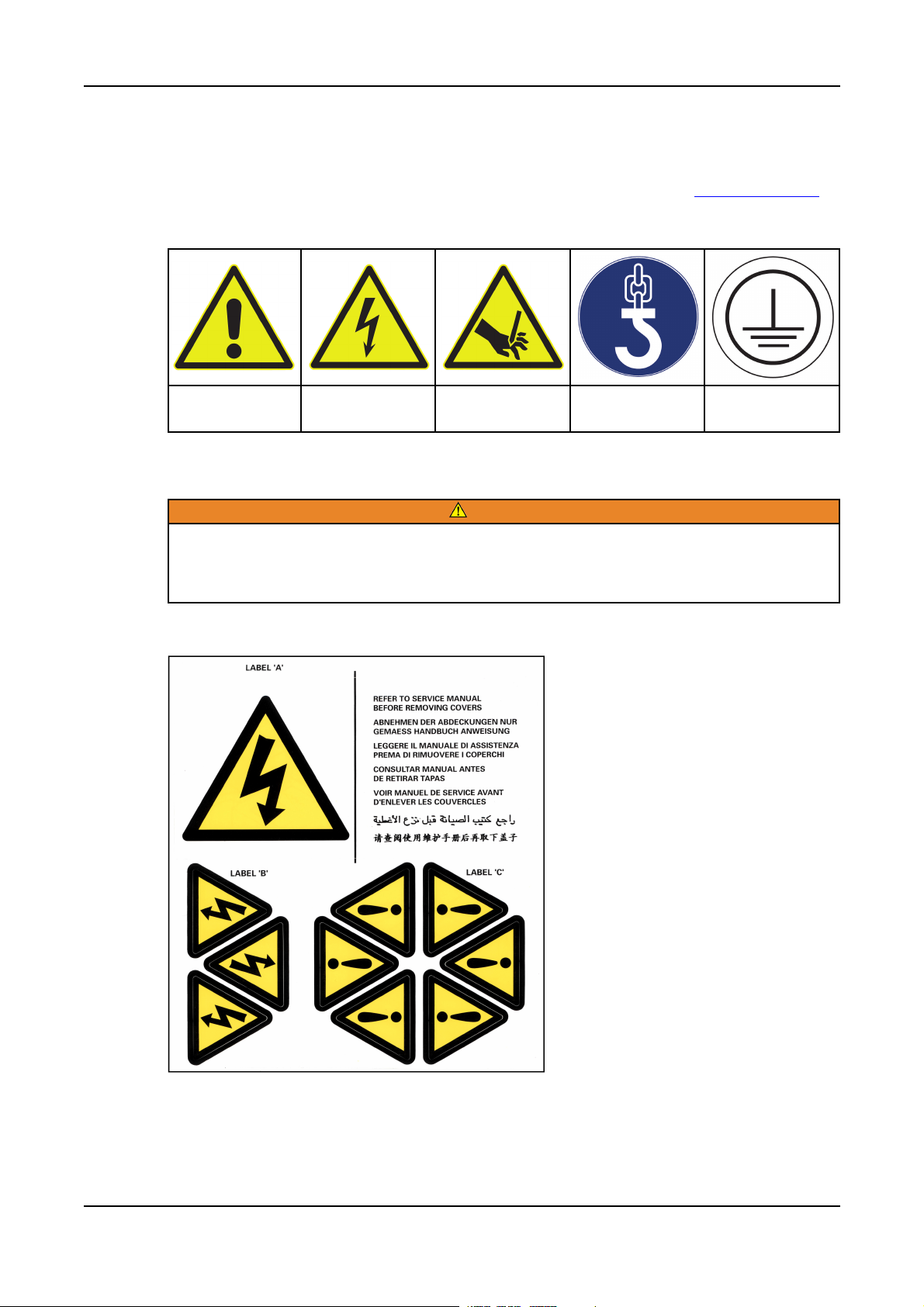
2.12 Safety Information Signs
Safety information signs are provided on the equipment to indicate hazards and emphasize
instructions. Become familiar with the signs and the meaning before operating the equipment. To
avoid injury, always take the necessary precautions. Sample signs are shown in Table 1 on page 7.
TABLE 1. SAFETY SIGN EXAMPLES
2. Safety Precautions03-2019
Warning Electrical Hazard Rotating Parts
2.12.1 Hazard Warning Labels
Hazard warning labels show the type and source of potential hazards. Observe the safety
labels to avoid risk of injury. The generator set manufacturer is responsible for fitting the
self-adhesive hazard warning labels supplied with the alternator. Labels must be fitted at the
locations shown on the back of the label sheet supplied with the alternator manual.
Replace labels that are missing, damaged or painted over.
WARNING
Mandatory
(Example: Lifting)
Protective
Conducter
7ING-WI-0395/A046V044 (Issue 7)
Page 16

2. Safety Precautions 03-2019
2.13 Oils and Grease
CAUTION
Hazardous Substances
Misuse of oils, grease or other chemical substances can lead to serious injury
When handling oils, greases and other chemical substances pay attention to the safety
regulations, appropriate PPE and environmental regulations that apply.
2.13.1 Solvents and Substances Containing Solvents
NOTICE
Pay attention to the safety regulations on handling solvents. Ask the manufacturer of the
solvent for safety data sheets and first aid measures in case of emergency! The safety data
sheets must be available before using the solvent.
On handling solvents or substances containing solvents always wear protective equipment such as
safety glasses, safety shoes, hard hat, protective gloves and suitable protective clothing to protect the
skin. Always use barrier cream.
Only use solvents in well-ventilated areas. To keep the exposure and hazards as low as possible, you
should:
1. Seal solvent containers immediately after use
2. Ensure that solvent and its vapors are not inhaled.
Solvents are combustible and flammable! A flame is not necessarily required for ignition, ignition
can also be triggered by hot objects at temperatures above the ignition temperature of the
solvent, or by electrical sparks (pay attention to electrostatic charging).
3. Do not bring organic solvents into contact with oxidizing agents (risk of explosion).
4. Ensure adequate ventilation!
Solvent vapors are heavier than air and can collect on the ground or in hollows. There is a risk of
asphyxiation and explosion!
First aid:
After inhaling larger quantities: copious fresh air, seek medical attention.
After contact with the skin: rinse thoroughly with water.
In case of contact with the eyes: rinse using eye bath and seek medical attention from an
ophthalmologist.
After swallowing: Seek medical attention
2.14 General Guidance
NOTICE
These safety precautions are for general guidance and supplement your own safety
procedures and all applicable laws and standards.
8 ING-WI-0395/A046V044 (Issue 7)
Page 17

2.14.1 General Safety Instructions
• Only use the alternator in correct working condition as well as in the manner intended, with due
consideration for safety and hazards while following the documentation and the local health and
safety regulations.
• Correct any malfunctions without delay that may affect safety or have them rectified by our
service organization.
• Always store this documentation with the alternator.
• Regularly check that personal work with due consideration for safety and hazards and follow the
documentation.
• Use appropriate personal protective equipment at all times
• Follow all information on safety and hazards on the alternator and maintain in legible condition.
• On the occurrence of safety-related changes on the alternator or in its operating behavior,
immediately shut down the alternator and correct malfunction without delay.
• Do not make any changes, additions or modifications to the alternator. This statement also
applies to installation and the settings for safety features.
• Do not circumvent or bypass any safety features. Before opening doors or covers for which the
use of a tool is required, the alternator must be shut down, electrically isolated and grounded.
2. Safety Precautions03-2019
• Service parts must comply with the technical requirements defined by the manufacturer. This
aspect is only ensured with genuine branded service parts. On the use of other service parts,
liability by the manufacturer is excluded.
• Do not make any changes to the program (software) in the programmable control system.
Changes to the program must only be made by appropriately trained personnel.
• Comply with stipulated intervals or intervals defined in the documentation for regular inspections
and servicing work.
• Use only appropriate tools for undertaking maintenance measures.
• Pay attention to fire alarm and firefighting procedures; pay attention to location and operation of
fire extinguishing systems (see Section 9.8 on page 74).
• Only allow trainees, apprentices or personnel under instruction or personnel undergoing general
training to work on the alternator under the constant supervision of an experienced person.
• Only task trained, experienced persons with the attachment of loads and signaling to crane
drivers. The person providing the signals must be visible for the operator.
• During installation work above head height, climbing aids and working platforms intended for this
purpose with appropriate safety features must be used. Do not use alternator components and
attachments as climbing aids! During servicing work at heights, wear fall arresting equipment.
• Keep all grips, steps, railing, pedestals, platforms, ladders free of debris and dirt.
• The alternator electrical equipment is to be checked regularly; loose connections or burnt,
damaged cables must be rectified immediately.
• If work is necessary on electrically live parts, involve a second person who can provide
immediate assistance in case of an emergency. Cordon off working area with a red-white safety
chain and a warning sign. Only use electrically insulated tools. Follow the local safety
regulations, e.g. VDE 0105
2.14.1.1 Safety Instructions for Normal Operation
• Refrain from all unsafe forms of working.
• Only operate the alternator if all protective devices and safety-related devices, e.g. detachable
protective devices, emergency stop devices, are fitted and functional.
• Inspect daily the alternator for externally visible damage and defects. Immediately report any
changes that have occurred (including changes in operating behavior) and immediately shut
down and secure the alternator.
9ING-WI-0395/A046V044 (Issue 7)
Page 18

2. Safety Precautions 03-2019
• In case of malfunctions, immediately shut down and secure alternator. Correct malfunction
without delay.
• Follow the documented procedures for switching on and switching off.
• Before switching on/placing in operation the unit, make sure no-one will be placed at risk by the
starting machine.
2.14.1.2 Safety Instructions for Special Tasks
Observe adjustment, servicing and inspection activities and intervals stipulated in the documentation
including information on the replacement of parts/assemblies. Service and maintenance procedures
and tasks should only be carried out by experienced and qualified engineers, who are familiar with the
procedures and equipment.
• Before starting special tasks and maintenance work, inform the operators. Nominate supervisor.
• During all work related to the operation, the adjustment for production, the conversion or the
adjustment of the alternator and its safety-related features as well as inspection, servicing and
repair, pay attention to switching on and switching off procedures as per the documentation and
instructions on maintenance work.
• Mark and cordon off maintenance area as far as necessary.
• When the alternator is completely switched off for servicing and repair work, it must be secured
against unintended switching back on using Lock out / Tag out:
◦ Cordon off switch panel and attach a lock and tag to the main switch.
• Make sure individual parts, as well as larger assemblies, are fastened to lifting equipment and
secured on replacement so that they can cause no harm. Only use suitable lifting equipment in
correct working order with adequate load bearing capacity. Do not stand or work under
suspended loads.
• At the start of servicing / repair, clean alternator of dirt and residue of anti-corrosion agents. Do
not use aggressive cleaning agents. Use fluff-free cloths for cleaning.
• After cleaning, check all oil, compressed air lines for leaks, loose connections, chafing and
damage. Correct any defects found immediately.
• If it is necessary to remove safety features during set-up, servicing and repair, the safety
features must be re-fitted and checked immediately on completion of the servicing and repair
work.
• Ensure any materials used are disposed of safely with due consideration for the environment.
2.14.2 General Guidance for Use
Incorrect handling, hazardous voltages, rotating parts and hot surfaces will shock, burn or
cause loss of limbs or death.
Adhere to all safety instructions.
DANGER
Alternators have dangerous, live and rotating parts and hot surfaces. All work in relation to transport,
storage, installation, connection, commissioning, operation and servicing must be done by authorized,
trained specialist staff. National standards, e.g. EN 50 110-1 / DIN VDE 0105 / IEC 60364 are to be
followed in the specific case.
It is forbidden to place the unit in operation until the end product is compliant with local regulations
(follow in particular local safety and installation regulations, e.g. EN 60204).
These machines comply with the IEC EN 60034 series of standards. It is forbidden to use them in
potentially explosive atmospheres.
10 ING-WI-0395/A046V044 (Issue 7)
Page 19

2. Safety Precautions03-2019
Under no circumstances use a degree of protection ≤ IP23 outdoors or in dusty environments.
Standard Air-cooled models are suitable for ambient temperatures from -15 °C to +40 °C and altitudes
of ≤ 1000 m above sea level. The ambient temperature for air/water-cooled models must not be less
than +5 °C without additional precautions. For alternators with sleeve bearings, the ambient
temperature must not be lower than 0° C. The oil temperature must be at least 15 °C for the start. (For
alternators with sleeve bearings also see the documentation from the bearing manufacturer). Pay
attention to any differing information on the rating plate. The conditions in the place of operation must
match all agreed information on the rating plate and in the specification.
In cases where there is a contradiction between the content of this manual and the machine supplied,
contact the manufacturer.
11ING-WI-0395/A046V044 (Issue 7)
Page 20

2. Safety Precautions 03-2019
This page is intentionally blank.
12 ING-WI-0395/A046V044 (Issue 7)
Page 21

3 Safety Directives and Standards
AvK alternators comply with European safety regulations as well as national and international
regulations on alternators issued in the EC. The alternator must be used in accordance with the
standards and intended use within the limits stated on the rating plate.
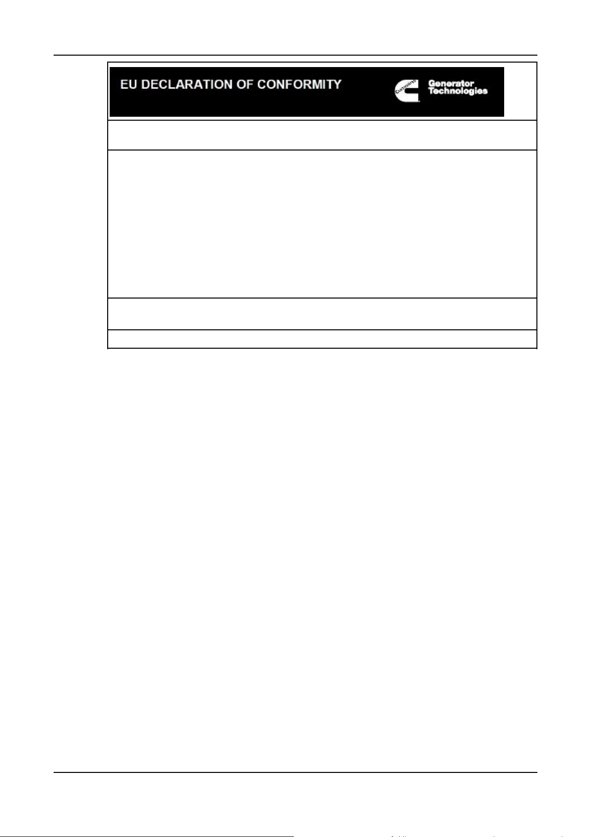
3.1 Low Voltage Directive: Declaration of Conformity Drawing
DSG alternators are supplied with an EC Declaration of Conformity. It is the responsibility of the
generator set manufacturer to ensure that the complete generator set complies with EC Directives and
Standards.
13ING-WI-0395/A046V044 (Issue 7)
Page 22

3. Safety Directives and Standards 03-2019
TABLE 2. LOW VOLTAGE DIRECTIVE: DECLARATION OF CONFORMITY
This synchronous A.C. generator is designed for incorporation into an electricity generatingset and fulfils all the relevant provisions of the following EC Directive(s) when installed in
accordance with the installation instructions contained in the product documentation:
2014/35/EU
2014/30/EU
2011/65/EU
2015/863
Low Voltage Directive
The Electromagnetic Compatibility (EMC) Directive
Restrictions on Hazardous Substances in Electrical and Electronic
Equipment (RoHS) Directive
Delegated Directive amending Anex II of 2011/65/EU
and that the standards and/or technical specifications referenced below have been applied:
EN 61000-6-2:2005
EN 61000-6-
4:2007+A1:2011
EN ISO 12100:2010
EN 60034-1:2010
BS ISO 8528-3:2005
BS 5000-3:2006
EN 50581:2012
Electromagnetic compatibility (EMC). Generic standards – Part 6-2:
Immunity for industrial environments
Electromagnetic compatibility (EMC). Generic standards – Part 6-4:
Emission standard for industrial environments
Safety of machinery – General principles for design – Risk
assessment and risk reduction
Rotating electrical machines - Part 1: Rating and performance
Reciprocating internal combustion engine driven alternating current
generating sets - Part 3: Alternating current generators for generating
sets
Rotating electrical machines of particular types or for particular
applications - Part 3: Generators to be driven by reciprocating internal
combustion engines - Requirements for resistance to vibration
Technical documentation for the assessment of electrical and
electronic products with respect to the restriction of hazardous
substances
This declaration has been issued under the sole responsibility of the manufacturer. The
object of this Declaration is in conformity with the relevant Union harmonization Legislation.
The name and address of authorised representative, authorised to compile the relevant
technical documentation, is the Company Secretary, Cummins Generator Technologies
Romania, B-dul Decebal Nr. 116A 200746 Craiova Dolj, Romania.
Date: 06thMarch 2019
Name, Title and Address:
Kevan J Simon
Global Technical Director
Cummins Generator Technologies Romania
B-dul Decebal Nr.116A
200746, Craiova
Signed:
Dolj, ROMANIA
Description Serial Number
Cummins Generator Technologies Ltd. Registered Office: Fountain Court, Lynch Wood, Peterborough, UK, PE2 6FZ
Registered in England under Registration No. 441273.
DRAWING REF 450-16383-G
14 ING-WI-0395/A046V044 (Issue 7)
Page 23
3. Safety Directives and Standards03-2019
The A.C. generator utilizes hazardous material exemptions as detailed in Annex III of EU Directive
2011/65/EU
Products carrying the following descriptions are considered to be out of scope of RoHS Directive
2011/65/EU, intended to be installed in Large Scale Fixed Installations and for installation into a predefined and dedicated location, installed and de-installed by professionals:
LVI80*
LVSI80*
DSG 99*
DSG 114*
DSG 125*
DSG 144*
Where * represents any combination of letters and characters completing the specific description of
the product.
Cummins Generator Technologies Ltd. Registered Office: Fountain Court, Lynch Wood, Peterborough, UK, PE2 6FZ
Registered in England under Registration No. 441273.
DRAWING REF 450-16383-G
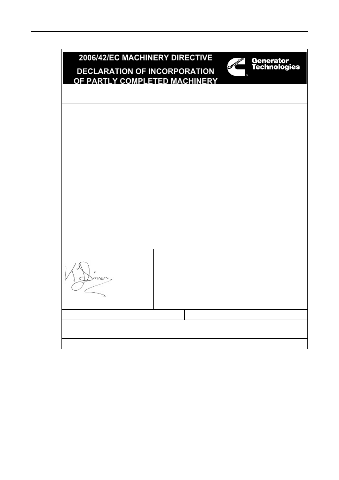
3.2 Machinery Directive: Declaration of Incorporation
DIG alternators are supplied with a "Declaration of Incorporation of Partly completed Machinery" for
incorporation into an electricity generating set. It is the responsibility of the generator set manufacturer
to ensure that the complete generator set complies with EC Directives and Standards.
15ING-WI-0395/A046V044 (Issue 7)
Page 24
3. Safety Directives and Standards 03-2019
TABLE 3. MACHINERY DIRECTIVE: DECLARATION OF INCORPORATION - SHEET 1
Function: Synchronous A.C. generator designed for incorporation into an electricity
generating-set.
The partly completed machinery supplied with this declaration:
• Is designed and constructed solely as a non-functional component to be incorporated
into a machine requiring completion.
• Is designed to comply with the provisions of the following EU Directives so far as their
level of build will allow:
2014/30/EU The Electromagnetic Compatibility (EMC) Directive
• Must not be put into service within the European Community ("EC") until the final
machinery into which it is to be incorporated has been declared in conformity with the
Machinery Directive and all other applicable EC Directives.
• Is designed and constructed to comply with the essential health and safety
requirements of the Machinery Directive 2006/42/EC listed on sheet 2 of this Declaration.
The relevant technical documentation is compiled in accordance with the provisions of part B
of Annex VII of the Machinery Directive. All relevant information about the partly completed
machinery will be provided, in writing, on a reasoned request by the appropriate national
authority to its authorised representative. The name and address of authorised
representative, authorised to compile the relevant technical documentation, is the Company
Secretary, Cummins Generator Technologies Romania, B-dul Decebal Nr. 116 A 200746
Craiova Dolj, Romania.
The undersigned representing the manufacturer:
Date: 06thMarch 2019
Name, Title and Address:
Kevan J Simon
Global Technical Director
Cummins Generator Technologies Romania
B-dul Decebal Nr.116A
200746, Craiova
Signed:
Dolj, ROMANIA
Description Serial Number
Registered in England under Registration No. 441273.
Cummins Generator Technologies Ltd. Registered Office: Fountain Court, Lynch Wood, Peterborough, PE2 6FZ, England.
A048T564-D
16 ING-WI-0395/A046V044 (Issue 7)
Page 25

3. Safety Directives and Standards03-2019
TABLE 4. MACHINERY DIRECTIVE: DECLARATION OF INCORPORATION - SHEET 2
ESSENTIAL HEALTH AND SAFETY REQUIREMENTS RELATING TO THE DESIGN AND
CONSTRUCTION OF PARTLY COMPLETED MACHINERY
1.1 General Remarks
• 1.1.2 : Principles of safety integration
• 1.1.3 : Materials and products
• 1.1.5 : Design of machinery to facilitate its handling
1.3 Protection Against Mechanical Hazards
• 1.3.1 : Risk of loss of stability
• 1.3.2 : Risk of break-up during operation
• 1.3.3 : Risks due to falling or ejected objects
• 1.3.4 : Risks due to surfaces, edges or angles
• 1.3.7 : Risks related to moving parts
• 1.3.8.1 : Moving transmission parts
1.4 Guarding
• 1.4.1 : Guards – General requirements
• 1.4.2.1 : Fixed guards
1.5 Other Hazards
• 1.5.2 : Static electricity
• 1.5.3 : Energy supply other than electric
• 1.5.4 : Errors of fitting
LEGEND
1. Essential Health and Safety
Requirements not shown are
not considered applicable for
this Partly Completed
Machinery or must be
fulfilled by the assembler of
the Machinery.
2. Essential Health and Safety
Requirements shown are
considered applicable for
this Partly Completed
Machinery and have been
fulfilled by the manufacturer
to the extent possible,
subject to the build
requirements of the
Machinery assembler, the
information contained in the
assembly instructions and
Cummins bulletins.
• 1.5.6 : Fire
• 1.5.13 : Emissions of hazardous materials and
substances
1.7 Information
• 1.7.1 : Information and warnings on the machinery
• 1.7.4 : Instructions
Registered in England under Registration No. 441273.
Cummins Generator Technologies Ltd. Registered Office: Fountain Court, Lynch Wood, Peterborough PE2 6FZ, England.
A048T564-D
17ING-WI-0395/A046V044 (Issue 7)
Page 26

3. Safety Directives and Standards 03-2019
This page is intentionally blank.
18 ING-WI-0395/A046V044 (Issue 7)
Page 27

4 Introduction
4.1 Serial Number
Each alternator is marked with a unique serial number. The serial number of this alternator is 81
34660 A001. It is marked on the rating plate on the alternator. (See Section 4.2 on page 19)
The serial number is to be stated in any future correspondence related to the alternator, as it is the
only information that is used to identify the specific alternator.
4.2 Rating Plate
Overheating
Can cause catastrophic failure and serious injury from ejected debris.
Always operate the alternator within the rated parameters specified on the rating plate .
A rating plate is permanently attached to the alternator and must not be removed. The rating plate
provides information on manufacture, identification, electrical and mechanical aspects.
WARNING
FIGURE 1. RATING PLATE
4.3 Important Remarks
In any areas of contradiction, the specific order-related documents take presidence.
In cases where there is a contradiction between the content of this manual and the alternator supplied,
contact Cummins Generator Technologies.
• The safety measures that are listed in the safety instructions in the manual must be observed at
all times.
NOTICE
19ING-WI-0395/A046V044 (Issue 7)
Page 28

4. Introduction 03-2019
Safety in the workplace is dependent on the alertness, care and common sense of all persons who
operate and service the machines. Along with the safety precautions recommended here, caution is
always required in the vicinity of machines: Pay attention to your safety!
NOTICE
The installation must comply with the instructions and regulations for health and safety. This
statement applies for general safety regulations in the related country, specific agreements
made for the related works, safety instructions included in this manual, and separate safety
instructions supplied with the alternator.
4.4 Liability, Warranty and Guarantee
All data and information in this documentation is provided based on our past experience and
knowledge.
The technical information and data described in this documentation relate to the situation at the date
of publication. We reserve the right to make changes in the context of technical further development
without changing this documentation. It is therefore not possible to derive any claims from the data
and descriptions in this documentation.
We accept no liability for damage or interruptions to operation due to operating errors, failure to follow
the instructions, improper servicing or repair. The manufacturer is not liable under any circumstances
for direct, indirect, specific, accidental or consequential damage, irrespective of its nature, that results
from the application of this document; the manufacturer is also not liable for accidental or
consequential damage that results from the use of the alternator.
We specifically highlight that service parts and accessories not supplied by us must be approved by
the manufacturer of the alternator.
Any additional liability for damage resulting from the use of service parts and accessories that have
not been approved by the manufacturer is excluded by the manufacturer.
Liability covers manufacturing and material defects.
Liability for damage caused by improper storage, incorrect installation or incorrect operation of the
alternator is excluded, as are the resulting injuries to the personnel or third party damage.
The installation and the use of third-party products will degrade the design features of the electrical
machine and impair the safety of people, the system or other property.
Any unauthorized modifications or changes to the alternator are not allowed for safety reasons and
exclude liability on the part of the manufacturer for resulting damage. If attachments/parts provided by
the customer are to be installed in or on the alternator, this action must be done in consultation with
the manufacturer.
Warranty and liability conditions in the manufacturer's general terms and conditions are not expanded
by the above statements.
NOTICE
Claims cannot be made under the warranty if the operating conditions of the alternator have
been changed, changes have been made to the design of the alternator or repair work has
been done on the alternator without prior written agreement from the manufacturer.
20 ING-WI-0395/A046V044 (Issue 7)
Page 29

4.5 Intended Use
4.5.1 Operating Conditions
4.5.1.1 Vibration Analysis
Serious damage (for example, destruction of the bearings, or cracks in the structure) may be
caused if the vibration allowed in the standard ISO 8528-9 or ISO 10816-3 is exceeded.
Serious damage (for example, destruction of the crankshaft, or destruction of the shaft) may
be caused if the torsional vibration is exceeded (e.g. ABS, LRS|). Ensure that the limits of the
Standards are adhered to.
It is the responsibility of the generating set builder to undertake the calculation, measurement and
evaluation of mechanical vibration in the power generating set (refer to standards ISO 8528-9 and ISO
10816-3).
It is imperative the rotational vibration calculation is made and checked.
4.5.1.2 Usage
4. Introduction03-2019
NOTICE
WARNING
Improper use.
Can cause hazards that could result in death or serious injury.
Always a operate in an accordance with the operation instructions.
NOTICE
Consult the manufacturer if you want to use the alternator in a different manner to that
described in the order documents.
The alternator is designed for onshore or maritime applications as per the order documentation.
4.5.1.3 Impermissible Forms of Operation
Do not operate the alternator:
• With operating data different to the data stated on the rating plate.
• With machine features modified by the operating organization.
• Outside the agreed specification
4.5.1.4 Permissible Forms of Operation
NOTICE
The alternator must only be used for the purpose stated in the order documentation. It must
be operated in accordance with the information in the documentation.
It is only allowed to operate the alternator
• In accordance with the procedures described in this documentation and
• If this documentation has been read and understood.
Any other use, as well as use involving hazardous or harmful substances is considered incorrect use.
21ING-WI-0395/A046V044 (Issue 7)
Page 30

4. Introduction 03-2019
NOTICE
Damage caused by operation otherwise than as intended or by incorrect operation is not
covered by the manufacturer's warranty and guarantee obligations. The risk is borne solely
by the user.
We recommend that operating hours, malfunctions, inspections, servicing and repairs are documented
in a log.
If malfunctions or damage cannot be rectified by the operating organization's specialist personnel,
please contact our customer service department.
For details of your nearest service outlet visit www.stamford-avk.com.
4.6 Documentation
4.6.1 Additional Information
NOTICE
Some customer-specific elements can be found in the Appendices. If the information in this
manual does not match the information in the Appendices, the data in the supplementary
documentation in the Appendices applies.
In addition to this manual, each set of documentation is supplied with a dimension drawing and rotor
drawing, an electrical circuit diagram as well as data sheets that state, among others, the following
order-specific information:
1. External dimensions of the alternator
2. Alternator weight
3. Moment of inertia of the rotor
4. Position of the lifting eyes on the alternator
5. Instrumentation and position of additional equipment
6. Requirements on bearing oil and lubricants
7. Main and ancillary connections.
4.6.2 Information not included in the Documentation
This user manual does not contain any information on starting, protection or rotational speed control
features as this is not part of our delivery scope.
22 ING-WI-0395/A046V044 (Issue 7)
Page 31

5 Transportation, Storage and
Corrosion Protection
5.1 Transportation and Packaging
5.1.1 General
The alternator is supplied on a transport frame with a transport lock.
The following protective measures are taken in the factory before the delivery of the alternator. If the
alternator is moved subsequently, the same protective measures are to be taken:
1. Protect machined surfaces
e.g. the seat for the drive coupling, are protected against corrosion using an anti-corrosion
coating.
5.1.2 General Information for Anti-Friction Bearings
Ball bearings and roller bearings are lubricated using a lubricant in the factory. The lubricant is stated
on the rating plate.
The first filling of the bearings with lubricant is adequate until the first re-lubrication interval, provided
the alternator is not stored.
5.1.3 General Information for Sleeve Bearings
The sleeve bearings are drained after the alternator test run; they are therefore delivered wet with oil.
All oil inlets and oil outlets as well as oil pipes are sealed. This method provides adequate protection
against corrosion. Sleeve bearings must be filled with oil during commissioning before operating the
alternator. The sleeve bearings must always be transported wet with oil but not filled with oil.
5.1.4 General Information for Air-Water Coolers
Air-water coolers are drained and the inlets and outlets on the cooler are sealed using protective caps.
5.1.5 Packaging
Packaging depends on the mode of transport (truck, ship, air freight).
The alternator is packed using environmentally-friendly materials (blocks of wood, wooden crates,
plastic sheet) that comply with the IPPC regulations.
• For transport by ship, the alternator must be packed for a maritime environment to protect
against splashes of salt water, moisture and vibration damage during loading, transport and
unloading
• For long transport routes, on customer request the alternator will be sealed with air- and dusttight plastic sheet with desiccant.
5.1.6 During Transport (DSG 125, DSG 144, DIG 140/150/156/163/167)
To avoid damage to the bearings:
• The alternator must be transported and moved using a suitable transport frame.
23ING-WI-0395/A046V044 (Issue 7)
Page 32

5. Transportation, Storage and Corrosion Protection 03-2019
The alternator must be transported and unloaded by persons who are familiar with the lifting
equipment and related ancillary equipment. All lifting equipment and tackle must be suitable for the
weight of the alternator and must comply with local safety regulations. Secure transport routes. Lifting
fixtures (for example, lifting eyes) must only be used to lift the item to which they are attached. Always
use the lifting features on the base frame to lift the complete generator set.
The transport eyes on the alternator are only to be used to transport the individual alternator, (not for
lifting a complete generator set)
NOTICE
Do not transport using a trolley over uneven surfaces (e.g. rails).)
• The transport markings (pictograms) on the alternator packaging must be observed during
transport.
• The alternator must only be supported at its feet. Support at other parts is not allowed.
If vibration is to be expected, the alternator must be isolated from vibration by placing suitable
vibration elements under the alternator feet.
The following information on transport is given in the alternator: Drawing KR31549.17
The text on the drawing is:
Every work activity/operation executed on the generator including rigging and hoisting has to be
accomplished by trained and experienced staff.
Do not stand below or close to the generator, while it is being lifted. Non-observance of these safety
precautions, as well as improper lifting can cause serious material damage, personal injury or even
death.
Only lift the generator at the lifting lugs attached to the housing. Please note that lifting lugs attached
to other components such as stator main structure must not be used to lift the complete machine.
They are only designed for assemblying the individual parts.
During transport the machine must only be supported on its feet. The weight of the machine must
never be supported by other parts than its feet.
If the generator is mounted on a base frame as complete system with a motor, use only the lifting
facilities provided on the base frame.
The lifting lugs on the generator are not designed to lift the complete gen-set.
For the transportation of the complete gen-set necessary safety arrangements have to be made, for
example to adjust the machine on anti-vibration elements or attach transportation locks.
Remark: Please check the dimension drawing for dimensions, actual weight as well as the centre of
gravity.
Lifting accessories for lifting the generator:
For lifting the generator, an appropriate and approved lifting equipment must be used.
The cooler must always be transported separately (at the lifting lugs on the cooler).
24 ING-WI-0395/A046V044 (Issue 7)
Page 33

5. Transportation, Storage and Corrosion Protection03-2019
FIGURE 2. TRANSPORT INFORMATION
5.1.7 During Transport (DIG 142)
To avoid damage to the bearings:
• The alternator must be transported and moved using a suitable transport frame.
The alternator must be transported and unloaded by persons who are familiar with the lifting
equipment and related ancillary equipment. All lifting equipment and tackle must be suitable for the
weight of the alternator and must comply with local safety regulations. Secure transport routes. Lifting
fixtures (for example, lifting eyes) must only be used to lift the item to which they are attached. Always
use the lifting features on the base frame to lift the complete generator set.
The transport eyes on the alternator are only to be used to transport the individual alternator, (not for
lifting a complete generator set).
NOTICE
Do not transport using a trolley over uneven surfaces (e.g. rails).
• The transport markings (pictograms) on the alternator packaging must be observed during
transport.
• The alternator must only be supported at its feet. Support at other parts is not allowed.
If vibration is to be expected, the alternator must be isolated from vibration by placing suitable
vibration elements under the alternator feet.
Every work activity/operation executed on the generator including rigging and hoisting has to be
accomplished by trained and experienced staff.
25ING-WI-0395/A046V044 (Issue 7)
Page 34

5. Transportation, Storage and Corrosion Protection 03-2019
Do not stand below or close to the generator, while it is being lifted. Non-observance of these safety
precautions, as well as improper lifting can cause serious material damage, personal injury or even
death.
Only lift the generator at the lifting lugs attached to the housing. Please note that lifting lugs attached
to other components such as stator main structure must not be used to lift the complete machine.
They are only designed for assemblying the individual parts.
During transport the machine must only be supported on its feet. The weight of the machine must
never be supported by other parts than its feet.
If the generator is mounted on a base frame as complete system with a motor, use only the lifting
facilities provided on the base frame.
The lifting lugs on the generator are not designed to lift the complete gen-set.
For the transportation of the complete gen-set necessary safety arrangements have to be made, for
example to adjust the machine on anti-vibration elements or attach transportation locks.
Remark: Please check the dimension drawing for dimensions, actual weight as well as the centre of
gravity.
Lifting accessories for lifting the generator:
For lifting the generator, an appropriate and approved lifting equipment must be used.
The cooler must always be transported separately (at the lifting lugs on the cooler).
FIGURE 3. TRANSPORT INFORMATION - DIG 142
5.1.8 During Transport (All DSG and DIG 110/120/130)
To avoid damage to the bearings:
• The alternator must be transported and moved using a suitable transport frame.
26 ING-WI-0395/A046V044 (Issue 7)
Page 35

5. Transportation, Storage and Corrosion Protection03-2019
The alternator must be transported and unloaded by persons who are familiar with the lifting
equipment and related ancillary equipment. All lifting equipment and tackle must be suitable for the
weight of the alternator and must comply with local safety regulations. Secure transport routes. Lifting
fixtures (for example, lifting eyes) must only be used to lift the item to which they are attached. Always
use the lifting features on the base frame to lift the complete generator set.
The transport eyes on the alternator are only to be used to transport the individual alternator, (not for
lifting a complete generator set).
NOTICE
Do not transport using a trolley over uneven surfaces (e.g. rails).
• The transport markings (pictograms) on the alternator packaging must be observed during
transport.
• The alternator must only be supported at its feet. Support at other parts is not allowed.
If vibration is to be expected, the alternator must be isolated from vibration by placing suitable
vibration elements under the alternator feet.
Every work activity/operation executed on the generator including rigging and hoisting has to be
accomplished by trained and experienced staff.
Do not stand below or close to the generator, while it is being lifted. Non-observance of these safety
precautions, as well as improper lifting can cause serious material damage, personal injury or even
death.
Only lift the generator at the lifting lugs attached to the housing. Please note that lifting lugs attached
to other components such as stator main structure must not be used to lift the complete machine.
They are only designed for assemblying the individual parts.
During transport the machine must only be supported on its feet. The weight of the machine must
never be supported by other parts than its feet.
If the generator is mounted on a base frame as complete system with a motor, use only the lifting
facilities provided on the base frame.
The lifting lugs on the generator are not designed to lift the complete gen-set.
For the transportation of the complete gen-set necessary safety arrangements have to be made, for
example to adjust the machine on anti-vibration elements or attach transportation locks.
Remark: Please check the dimension drawing for dimensions, actual weight as well as the centre of
gravity.
Lifting accessories for lifting the generator:
For lifting the generator, an appropriate and approved lifting equipment must be used.
The cooler must always be transported separately (at the lifting lugs on the cooler).
27ING-WI-0395/A046V044 (Issue 7)
Page 36

5. Transportation, Storage and Corrosion Protection 03-2019
FIGURE 4. TRANSPORT INFORMATION - DSG AND DIG 120/130
5.1.9 Unpacking Checks/Items supplied
Check that the items supplied correspond to the order specification and the delivery note. We refer to
our terms and conditions of sale and supply.
5.1.10 Inspection on Arrival
Check the alternator and all supplied parts immediately it arrives. Check for evidence of improper
handling. Any transport damage must be photographed and reported to the freight carrier and the
supplier within seven days, so a claim can be made against the transport insurance.
If the alternator is not to be installed immediately do not leave it to stand without further protection. For
further details see Section 5.2 on page 29.
5.1.11 Inspection on Unpacking
Place the alternator on a flat surface free of vibration. Ensure there is sufficient access to the
alternator and associated components.
Remove the packaging and check that the alternator is not damaged. Compare the delivery with the
delivery note enclosed to check that additional items are present. If damage is suspected or an item is
missing, take photographs that clearly show the problem and contact the freight carrier and the
supplier immediately.
Refer to Section 13.4 on page 130 for the correct disposal and recycling of the packaging material.
28 ING-WI-0395/A046V044 (Issue 7)
Page 37

5. Transportation, Storage and Corrosion Protection03-2019
5.2 Storage
5.2.1 Storage in a Suitable Room (less than 6 Months)
CAUTION
Fire Hazzard
Will burn, cause personal injury or could cause death
Make sure no highly flammable or flammable objects are stored in the vicinity of the anti-
condensation heater or alternator packaging.
Suitable conditions are:
• Stable temperature conditions between 10 ºC (50 ºF) and 50 ºC (120 ºF).
• The alternator must not exceed 50 °C (120 ºF) .
• The ambient air must be clean and free of dust and corrosive gases or salt-laden aerosols.
• Low atmospheric humidity (below 75%) is required. The alternator temperature must be
maintained above the dew point to prevent condensation in the alternator.
• If the alternator has an anti-condensation heater, the heater must be switched on and its function
checked regularly. The temperature of the alternator is also to be monitored.
• If there is no anti-condensation heater, or it cannot be switched on, use an alternative heat
source to protect the alternator against condensation.
• A stable surface free of vibration, protected against knocks. If vibration is expected, isolate the
alternator by placing suitable vibration elements under the feet.
• All bare surfaces on the alternator are protected on delivery. Check the protection regularly and:
1. Clean any rust film and other dirt from bare surfaces (ends of shaft, flange, screws etc.).
2. Seal the cleaned surfaces using a complete layer of protective lacquer or protective wax
(Tectyl 511M or 846K).
3. If the period of storage/idle exceeds two months, Tectyl 511 or equivalent should be sprayed
through the filler opening into the sleeve bearing.
5.2.2 Storage in a Suitable Room (longer than 6 Months)
WARNING
Fire Hazard
Will burn, cause personal injury or could cause death
Make sure no highly flammable or flammable objects are stored in the vicinity of the anti-
condensation heater or alternator packaging.
Suitable conditions are:
• Stable temperature conditions in the range from 10 ºC (50 ºF) to 50 ºC (120 ºF). The alternator
temperature must be kept above the dew point to prevent condensation in the alternator.
• A dust-free, dry environment with low atmospheric humidity (below 75%) is required. If this
requirement cannot be met, the alternator is to be stored welded in plastic sheet with desiccant.
• The ambient air must be clean and free of dust and corrosive gases or salt-laden aerosols.
• If the anti-condensation heaters are switched on and the temperature of the ambient air is above
50 ºC, the alternator must not heat up to above 50 ºC (120 ºF)
◦ If the alternator has an anti-condensation heater, the heater should be switched on and its
function checked regularly.
29ING-WI-0395/A046V044 (Issue 7)
Page 38

5. Transportation, Storage and Corrosion Protection 03-2019
◦ If there is no anti-condensation heater, or it is not possible to place it in operation, an
alternative method is to be used to protect the alternator against condensation.
• Make sure the alternator sits on a stable surface free of vibration and protected against knocks.
If vibration is to be expected, the alternator must be isolated by placing suitable vibration
elements under the alternator's feet.
• All bare surfaces on the alternator are protected on delivery. Regularly check the protection and
proceed as follows in case of damage:
1. Clean any rust film and other dirt from bare surfaces (ends of shaft, flange, screws etc.).
2. Cover cleaned surfaces using protective lacquer or protective wax (Tectyl 511M or 846K).
3. Ensure the layer of lacquer provides a seal!
4. Sleeve bearings are to be protected against corrosion in accordance with the information
from the sleeve bearing manufacturer and their protection regularly checked.
5. Additionally, Cummins recommends to add a drying agent to the sleeve bearing housing.
By storage longer than 18 months, the bearing shelves of sleeve bearings must be replaced.
5.2.3 Storage in Unsuitable Conditions (less than 2 Months)
Protect the alternator against insects and other small animals. Prevent corrosion, moisture or the
formation of condensation in and on the alternator. For temporary outdoor storage during transport or
if suitable store room conditions are not available, the alternator must not be left unprotected in the
transport packaging. The following measures are to be taken in addition to the measures in Section
5.3.3 on page 31:
1. Fully protect the alternator from rain. The cover must be well ventilated to permit the circulation
of air around the alternator. If the alternator is left in the transport packaging, ventilation openings
must be made in the packaging.
2. Place alternator with transport frame on blocks so that no moisture can enter the alternator or the
transport frame from below. The transport frame and the alternator must be at least 100 mm (4
inch) off the ground.
3. Make sure the alternator is well ventilated. Switch on the anti-condensation heater.
DANGER
Hazardous voltage.
Will shock burn or cause death.
Faulty electrical components can be live and as a result life-threatening. Any defects found in
electrical systems, assemblies, equipment must be rectified without delay. If there is an acute
risk until rectified, the system or the assembly must not be used in the defective state.
5.2.4 Storage in Unsuitable Conditions (longer than 2 Months)
By storage under unsuitable conditions longer than 2 months, the warranty will expire immediately
unless an exception has been granted by contacting the supplier in writing.
5.3 Protect Against Corrosion
5.3.1 Bare Surfaces
List the corrosion protection measures taken, check their effectiveness with the manufacturer and
check them regularly. Correct any malfunctions and treat corrosion immediately.
1. Make sure the lacquer or wax seals the part to protect it
2. The ambient air must be clean and free of dust and corrosive gases or salt-laden aerosols
30 ING-WI-0395/A046V044 (Issue 7)
Page 39

3. All bare surfaces on the alternator are protected with Tectyl or protective lacquer on delivery.
Regularly check the protection and proceed as follows in case of damage:
a. In case of damage, clean any rust film and other dirt from bare surfaces (ends of shaft,
flange, screws etc.).
b. Cover cleaned, damaged surfaces using protective lacquer or protective wax (Tectyl 511M
or 846K).
5.3.2 Sleeve Bearings
If the transport lock is re-tightened to a higher torque, the bearing will be damaged. In case of
questions please contact the manufacturer.
Refer to the Appendix from the sleeve bearing manufacturer. If the instructions in the Appendix vary
from those in this manual, the instructions in the Appendix apply.
To protect the sleeve bearings against corrosion take the following measures:
• Fittings on the sleeve bearings are sealed in the factory and sealing lacquer applied.
1. If the sleeve bearing has already been filled with oil (e.g. after test run on the unit), drain
this oil.
5. Transportation, Storage and Corrosion Protection03-2019
NOTICE
2. Spray Tectyl 511 or equivalent with a compressed air tool through the filler opening into the
bearing. Repeat this corrosion protection treatment every six months for two years. For this
purpose it is recommended to open the packaging at the bearings.
3. Check the compatibility of synthetic oil with bearing materials, corrosion protection
materials and oil filling.
4. Remove the sight glass for the oil ring, remove the oil and open the oil drain (see Figures
2&3).
5. Spray corrosion protection agent into the openings using compressed air.
6. The parts of the bearing must be fully covered with lubricant to prevent corrosion during the
storage period.
7. Seal the sight glasses and the oil drain.
8. Repeat the procedure on the second bearing.
9. After protection against corrosion, carefully re-seal the packaging to prevent corrosion due
to external effects.
Alternators with sleeve bearings are fitted with a transport lock to protect the bearing against damage
during transport and storage.
Check the transport lock for bolt tightness regularly.
5.3.3 Anti-Friction Bearings
After storage for more than 2 years the bearings and the grease must be replaced before
commissioning the alternator.
If the transport lock is re-tightened to a higher torque, the bearing will be damaged. In case of
questions please contact the manufacturer.
To prevent brinelling of anti-friction bearings during storage:
1. Pre-load the bearing using the transport lock.
2. Remove the transport lock and Turn the rotor monthly so that the position of the rolling elements
changes. The rotor must rotate at least 420 ° .
3. Fill the entire bearing chamber with grease.
31ING-WI-0395/A046V044 (Issue 7)
Page 40

5. Transportation, Storage and Corrosion Protection 03-2019
5.3.4 Air-Air Cooler
Check the effectiveness of the corrosion protection measures annually. Or more frequently in
particularly unfavorable ambient conditions. Renew the corrosion protection measures if necessary.
1. Clean the entire cooling path by blowing out with dry air.
5.3.5 Air-Water Cooler
Check the effectiveness of the corrosion protection measures annually. Or more frequently in
particularly unfavorable ambient conditions. Renew the corrosion protection measures as necessary.
1. Drain the existing cooling water.
2. Clean the cooling water pipes and flush using clean, clear water.
3. Dry the cooler with warm, pre-dried air.
5.3.6 Customer Connection Openings
Clean the cooler and pipes and blow through warm, dry air to dry them. Seal the openings through
which cables are not yet connected to terminal boxes or flanges that are not yet connected to pipes.
5.4 Remove Corrosion Protection
Do not remove the anti-corrosion coatings using emery paper.
Before operating a corrosion-protected alternator, remove the measures taken and logged for storage
and establish the state required to perform commissioning
• Remove any drying agent that may have been placed in the alternator.
• Remove the anti-corrosion coatings using cleaner´s solvent or a similar oil-based solvent.
• Ensure that all necessary fluids (e.g. oil, grease, water) are added in the correct amount to the
alternator before it is taken into operation.
5.4.1 Anti-Friction Bearings
Check which measures were applied for protection against corrosion, remove as appropriate.
The amount of grease in the bearings for long-term storage must be reduced to the specified amount
for operating the alternator. Open the bearing chamber, remove the excess grease and re-seal the
bearing chamber. In case of questions related to the amount of grease, please contact the
manufacturer with the machine number.
An excessive amount of grease or old grease in the bearings during operation will result in
serious bearing damage! Pay regard to the storage time and the grease amount.
NOTICE
NOTICE
Check the amount of grease in the attachments. If necessary contact the manufacturer for information
on the first filling.
5.4.2 Sleeve Bearings
The removal of the protection against corrosion in the sleeve bearings and further steps are described
in the operating instructions for the sleeve bearings.
32 ING-WI-0395/A046V044 (Issue 7)
Page 41

After extended storage, check the bearings for corrosion damage.
1. Clean the bearing housing from the exterior. Dust and dirt will hinder the dissipation of heat from
the bearing.
2. Remove any drying agent that may have been placed in the bearing housing.
3. Re-tighten the joint screws and the flange screws as follows.
Take the torques from the documentation from the manufacturer of the sleeve bearing or contact the
manufacturer with the machine number.
1. Check that the sight glass is correctly seated.
2. Check the sight glass for the oil ring on the top of the bearing. This should be tightened handtight (12-16 Nm)
3. Tighten all plugs to the required tightening torque.
5.4.3 Cooler
Follow the operation and maintenance instructions supplied by the cooler manufacturer.
5.4.3.1 Air-Water Cooler
Fill and operate the water circuit according to the operating and maintenance instructions from the
cooler manufacturer. You will find these instructions in the Appendix.
5. Transportation, Storage and Corrosion Protection03-2019
5.4.3.2 Air-Air Cooler
Operate the air-air cooler according to the operating and maintenance instructions from the cooler
manufacturer. You will find these instructions in the Appendix.
5.4.4 Condensed Water Drain
Harzardous Voltage
Will shock, burn or cause death.
In case of condensed water, do not operate the alternator without the repairs and inspections
described in Chapter 10 on page 77.
Check whether condensed water has formed in the alternator. If there is condensed water present,
open the drain plug at the lowest point on the alternator and close again after draining the condensed
water.
DANGER
33ING-WI-0395/A046V044 (Issue 7)
Page 42

5. Transportation, Storage and Corrosion Protection 03-2019
5.5 Oil Drain Points
TABLE 5. NON DRIVE END
No Description
1 Oil Ring Sight Glass
2 Oil Sight Glass
3 Oil Drain
TABLE 6. DRIVE END
No Description
1 Oil Ring Sight Glass
2 Oil Sight Glass
3 Oil Drain
34 ING-WI-0395/A046V044 (Issue 7)
Page 43

6 Installation and Alignment
6.1 General
DANGER
Hazardous voltage and rotating parts.
Will shock, burn, or cause loss of limbs or death.
Prevent unintentional operation of the alternator and accidental damage caused when work is
done nearby.
Follow general and local health and safety instructions during installation.
Good planning and comprehensive preparations before installation are necessary for malfunction-free,
reliable and safe operation of the alternator.
Follow the standards for connections and use of electrical equipment, in particular national standards,
for the installation of the equipment (e.g. see standard IEC 60079-14 or EN 60204).
When welding, do not use alternator as (earth) ground.
6.2 Preparation of the Alternator
Prepare the alternator as follows before installation:
1. Measure the insulation resistance of the windings as described in Section 7.4.4 on page 50.
2. If necessary, remove the transport lock. Keep it in a safe place for future use. To prevent bearing
damage the transport lock must always be attached to the alternator if the alternator is moved, or
placed in storage. See Section 5.1.1 on page 23.
3. Remove the anti-corrosion coating from the end of the rotor shaft and the alternator feet using
white spirit or a similar oil-based solvent.
6.2.1 Alternators with Anti-Friction Bearings
Alternators with two bearings must be connected to the prime mover using elastic couplings to ensure
continuous free axial movement between the coupling halves due to thermal expansion of the
alternator shaft without bearing damage.
In general, the non drive end bearing is fixed but for special applications on customer demand it is
possible to build the drive end bearing fixed. If in doubt, ask Cummins. The axial thermal expansion of
the rotor is calculated as described in Section 6.4.3 on page 41. If in doubt, contact the manufacturer.
• Make sure the grease is compliant with the specification on the rating plate and make sure the
bearing is filled with the correct amount of grease. See Section 5.4 on page 32.
NOTICE
An excessive amount of grease or old grease in the bearings during operation will result in
serious bearing damage. Pay regard to the storage time and the grease amount.
6.2.2 Alternators with Sleeve Bearings
1. The drive-end bearing is always fixed. Fill the sleeve bearing with oil. For this purpose refer to
the outline drawing for the viscosity of the oil. If a lubricant is not stated on the outline drawing,
use the lubricant recommended by the sleeve bearing manufacturer.
35ING-WI-0395/A046V044 (Issue 7)
Page 44

6. Installation and Alignment 03-2019
6.2.3 Recommendations for Coupling Assembly
6.2.3.1 Balance Condition of the Rotor
Balance the rotor coupling half corresponding to the rotor balancing. A standard rotor is dynamically
balanced using half keys. The type of balancing is marked on the end of the rotor shaft:
H = Half key
F = Whole key
N = No key
6.2.3.2 Assembly
WARNING
Rotating Parts.
Will cause severe injury. The coupling is to be protected with a guard. There is a hazard in
operation due to rotating parts.
In operation, be careful of rotating parts.
WARNING
Hot parts.
Cause serious burns.
Prevent skin contact with hot parts using PPE.
1. Follow the coupling-specific instructions from the coupling manufacturer.
2. The coupling can be heavy; use suitable lifting equipment.
3. Clean the anti-corrosion coating from the coupling seat on the shaft and compare the dimensions
of the end of the shaft and the coupling with the outline drawing provided.
4. Make sure that the key slots in the coupling and the shaft are clean, free of burrs and
undamaged.
5. Lubricate the shaft and the hub bore with a thin layer of resin-free oil to ease the assembly of the
coupling half.
Never lubricate mating surfaces with molybdenum disulfide (MoS2) or similar products.
6. If it is necessary to heat the coupling to ease fitting, follow the temperature information from the
coupling manufacturer.
7. For assembly of heated couplings we recommend to have the key at bottom dead center (on
6:00 position below shaft), to prevent surface damage on the shaft and hub beside the key.
To prevent damage to the bearings, do not put additional forces on the bearings while assembling the
coupling half. If axial pressure is required to assemble the coupling hub, use the threaded center bore
in the alternator shaft to install a pushing rod.
6.3 Mounting Design
6.3.1 General
The mounting design and construction is the responsibility of the customer or a third-party. The
mounting design must ensure safe operating conditions and good access for servicing and monitoring.
Cooling airflow must be unhindered to and from the alternator. Nearby machines or equipment must
not heat the cooling air for the alternator or its attachments, such as the bearings.
36 ING-WI-0395/A046V044 (Issue 7)
Page 45

The mounting must be stable, stiff and free of external vibration. Check for resonance; the natural
frequency of the mounting with mounted alternator must not lie within ±20% of the operating
frequency.
The mounting must be designed to support the weight of the alternator and include air, water, oil and
cable ducts. The dimensions of the connection features must match the corresponding dimensions on
the outline drawing provided.
The mounting must be designed to accomodate all the manufacturing tolerances.
6.3.2 Mounting Forces
The mounting and the fastening screws must withstand mechanical moments that occur during
alternator starting, operation and transient events. Refer to the technical data sheet for the loads.
The calculation of the mounting forces is not included in the items supplied, for this reason the
customer or a third-party is responsible for this task. If necessary, calculation can be agreed in the
project planning phase.
6.3.3 Mounting on Marine Applications
6.3.3.1 General Requirements
The classification and design requirements of the certification authority apply to the design and
implementation of mountings on marine applications.
6. Installation and Alignment03-2019
6.3.3.2 Calculations
Check and calculate during the project phase
1. The natural frequency of vibration in the overall system in 6 degrees of freedom.
2. Calculate the static displacements in x, y and z directions on all elastic components. Take into
account all loads effective at nominal power output due to the inherent weight of the motor, the
motor nominal torque (or output torque for flange-mounted gearboxes), and ship pitch and roll
motion.
3. Compare the displacement values calculated with the values allowed for the electrical
components.
4. Calculate the forced damped vibration.
The result must conform to the specifications for the marine classification and be agreed with the
manufacturer of the component.
6.3.3.3 Fastening Alternator to Base
Only screw joints must be used for fastening the drive systems to the ship-borne mounting.
To keep settling to a minimum, the number of joints in the screw joints is to be limited to a minimum.
The contact surfaces for screw heads and nuts must be flat and machined parallel.
Do not tack weld alternator mounting screws and nuts.
The screw joint must be designed for the maximum possible load that can occur.
The required pre-load on the mounting screws is to be defined in agreement with the manufacturer of
the prime mover or the manufacturer of the related system component.
The preferred fastener type is a cap screw, installed so that the screw pre-load can be checked at any
time.
6.3.3.4 Requirements
Follow the manufacturer's installation regulations during the mechanical mounting of the individual
components on the foundation.
Design of the mounting must be agreed with the certification authority.
37ING-WI-0395/A046V044 (Issue 7)
Page 46

6. Installation and Alignment 03-2019
Make sure the assembly and inspection openings on the drive systems provided for maintenance
measures remain accessible.
Final fastening must be done after alignment done. Consider the operation-related thermal expansion
and the dynamic behavior of the system components (coupling, gearbox etc.) during alignment.
Make sure that the alignment of the individual system components to each other does not change
during mechanical work on the mounting.
All welding work in the area of the mounting must be completed before mounting the alternator.
During the design of a resiliant mounting, consider the aging and natural wear of the mounting
elements. Check and log the settling rates at intervals specified by the manufacturer. Replace the
elastic mounting when the maximum allowed amount of settling occurs.
6.3.4 Installation on Concrete Foundations
6.3.4.1 Items Supplied
The installation shims, fastening screws and mounting pads or bed plates are not included in the
normal items supplied with the alternator. These can be supplied to special order.
6.3.4.2 Calculations
Check and calculate during the design phase
1. The natural frequency of vibration for the overall system in 6 degrees of freedom.
2. Calculate the forced damped vibration.
3. Calculate the mounting forces and screw joints
The results must conform to the specifications and be agreed with the manufacturer of the related
system component.
6.3.4.3 Prepare the Foundation and the Holes in the Foundation
Mounting pads in accordance with DIN 799 or bed plates can be used to anchor the alternator in a
concrete foundation.
Take into account the following points during the preparation of the foundation:
• Compare the position of the holes in the foundation and the height of the foundation with the
related dimensions on the outline drawing.
6.3.4.4 Prepare the Mounting Pads or the Bed Plates
If required, shims and mounting pads are supplied as separate parts for fitting on site.
To ensure the firm seating of the mounting pads in the concrete, they must be unpainted and free of
dirt and dust.
1. Lift the alternator with a crane to assemble the mounting pads or bed plates to the alternator.
2. Clean the parts that are cast in the concrete.
3. Clean parts protected with an anti-corrosion coating using solvent.
4. Only use greased alignment screws into the mounting pads or bed plates.
Make sure that clearances and fasteners are free of concrete.
6.3.4.5 Install the Alternator
Lift the alternator carefully and, together with the coupling half and bed plates or mounting pads, fit it
into the holes that have been made on the existing foundation. The coupling is fitted in accordance
with the specifications from the coupling manufacturer.
38 ING-WI-0395/A046V044 (Issue 7)
Page 47

6.3.4.6 Position the Mounting Pads or the Bed Plates
The bed plates or mounting pads must either be positioned together with the alternator or separately,
so that the alternator can be aligned afterwards within the range of its adjustment features.
6.3.4.7 Cementing
NOTICE
Cracks in the concrete or poor fastening to the concrete foundation can loosen the alternator.
Fill the holes in the foundation completely and avoid cavities.
Cementing the alternator in the foundation is a very important part of the installation. Follow
the instructions of the concrete manufacturer.
Use high-quality concrete that is not subject to shrinkage to prevent problems during
cementing.
6.3.4.8 Final Installation and Inspection
1. After the concrete has hardened, re-tighten the foundation bolts.
2. Lock the nuts using an approved locking system.
6. Installation and Alignment03-2019
3. Tighten the fastening screws.
4. Check and correct the alignment to ensure the alternator runs with the permissible vibration.
5. Complete the installation by fitting dowel pins.
6.3.5 Installation on Steel Foundation
6.3.5.1 Items Supplied
Installation shims or fastening screws are not included in the normal items supplied. These can be
supplied to special order.
6.3.5.2 Inspect the Foundation
Before lowering the alternator onto the foundation:
1. Clean the foundation thoroughly
2. Check that the foundation is flat and level (parallel error maximum 0.1 mm (4.0 mil))
3. Check that the foundation is free of external vibration.
6.3.5.3 Install the Alternator
Lift the alternator carefully and, together with the coupling half, fit it on the existing foundation. The
coupling is fitted according to specifications from the coupling manufacturer.
6.3.5.4 Coupling Cover and Enclosures
Before fitting enclosures and operating the alternator but after installing and aligning the alternator,
make sure that there are no tools or foreign bodies left inside the alternator or the enclosures.
WARNING
Rotating parts.
Can cause loss of limbs or death.
The coupling must be protected with a guard. In operation, be careful of rotating parts.
Keep the alignment and installation equipment together with the transport lock for future use.
39ING-WI-0395/A046V044 (Issue 7)
Page 48

6. Installation and Alignment 03-2019
6.4 Align the Prime Mover and Alternator
6.4.1 General
To ensure a long, satisfactory service life for both the prime mover and the alternator, both must be
correctly aligned. This means that the radial and angular offset between the two shafts on the
machines must be minimized.
Be sure to complete an alignment report. Claims relating to damage can only be considered if an
alignment report is available. Before starting the alignment work, remove all transport locks and rotor
fastenings. Undertake alignment with great care, as alignment errors will result in bearing and shaft
damage. Even small alignment errors will result in uneven running of the machines and bearing
damage.
6.4.2 Theory of Alignment
The accuracy of alignment is related to the tools used for the alignment (dial gauges, laser measuring
instrument).
• A laser measuring instrument is most accurate.
One of the two machines to be coupled is defined as the reference point.
On power generator sets this reference point is generally the prime mover.
• Fine alignment is dependent on the design of the machine, as follows:
TABLE 7. ALIGNMENT OFFSET AND
SPEED
Nominal speed
1800 revs/min 0.05 mm / 2 Mils
1500 revs/min 0.06 mm / 2.5 Mils
1000 revs/min 0.08 mm / 3 Mils
750 revs/min 0.09 mm / 3.5 Mils
600 revs/min 0.11 mm / 4 Mils
375 revs/min 0.15 mm / 6 Mils
General figure for the angular offset: ≤ 0.05 mm / 100 mm (5 Mils / 10 inch) coupling diameter
Axial coupling position of the prime mover to alternator has to be within coupling manufacturer's
specifications.
Maximum radial
offset
FIGURE 5. RADIAL OFFSET
40 ING-WI-0395/A046V044 (Issue 7)
Page 49

6. Installation and Alignment03-2019
FIGURE 6. ANGULAR OFFSET
FIGURE 7. AXIAL OFFSET
The alternator, gearbox and prime mover may have different coefficients of thermal expansion. Take
this into account when aligning at ambient temperature, so that the generator set is aligned when at
operating temperature. (see section below).
6.4.3 Compensate for Thermal Expansion
Operating temperatures have a significant effect on alignment and must be taken into account. The
temperature of the alternator under operating conditions is higher than during installation. The center
of the shaft will be higher during operation, i.e. further away from the base than at rest due to thermal
expansion.
Thermally-compensated alignment may be necessary depending on the operating temperature of the
alternator, the type of coupling, the distance between the two machines etc.
6.4.3.1 Vertical Thermal Expansion
Vertical thermal expansion is always to be taken into account.
The thermal expansion of the alternator can be calculated approximately using the distance between
the base and the center of the shaft:
∆H = α × ∆T × H
Where
∆H= Thermal expansion [mm]
α= 10 × 10-6 K
∆T= Temperature difference between alignment temperature and operating temperature to be
expected [°K]
H= Shaft height [mm] (see outline drawing)
Take into account the thermal expansion of the alternator in relation to the prime mover to determine
the overall thermal expansion.
-1
6.4.3.2 Axial Thermal Expansion
Axial thermal expansion is always to be taken into account.
The calculation is made from the fixed bearing on the alternator to the end of the shaft on the drive
side (see rotor drawing in the Appendix).
41ING-WI-0395/A046V044 (Issue 7)
Page 50

6. Installation and Alignment 03-2019
The fixed bearing is on the B end (NDE - non-drive end) of the alternator for anti-friction bearings and
on the A end (DE - drive end) of the alternator for sleeve bearings. In case of queries related to the
fixed bearing and the thermal expansion please contact the manufacturer.
The thermal expansion can be calculated approximately using the distance between the fixed bearing
and the other end of the rotor shaft:
∆L = α × ∆T × L
Where
∆L= Thermal expansion [mm]
α=10 × 10-6 K
∆T= Temperature difference between alignment temperature and operating temperature to be
expected [°K]
L= Distance from the fixed bearing to the AE of the shaft [mm]
Make sure that continuous free axial movement is possible between the coupling halves (except fixed
couplings) to permit axial thermal expansion of the alternator shaft and prevent bearing damage.
-1
6.4.4 Assemble the Coupling Halves
The coupling halves are assembled in accordance with the requirements from the coupling
manufacturer. The coupling halves on the prime mover and alternator are placed together loosely so
that they can move freely in relation to each other during the alignment.
6.4.4.1 Run-out on the Coupling Halves
NOTICE
Do not turn alternator rotor using the fan. The fan will not withstand such forces and will be
damaged.
The alignment process starts with the measurement of the run-out on the coupling halves. This
measurement provides an indication of any inaccuracy on the shaft and/or the coupling halves.
The run-out on the coupling halves is measured in relation to the alternator bearing housing. Fit the
dial gauges as shown in Figure 8 on page 42. Rotate the rotor shaft with a simple lever. Check the
run-out of the coupling half on the prime mover in relation to the bearing housing.
Fill sleeve bearings with oil before rotating. The permissible run-out error is less than 0.05 mm (1.9
mil).
FIGURE 8. MEASUREMENT OF THE RUN-OUT ON THE COUPLING HALF
42 ING-WI-0395/A046V044 (Issue 7)
Page 51

The alignment must be performed with great care. Otherwise, the prime mover and the alternator can
be seriously damaged by heavy vibration. Measure alignment performed according to instructions from
the coupling manufacturer. Parallel, angular and axial alignment of the alternator is required.
6.4.5 Coarse Alignment
For ease of alignment and the fitting of shims, alignment screws are fitted to the alternator base.
The alternator stands on the alignment screws. Please note that the alternator must stand on all feet
(screws) in a plane with a maximum of 0.1 mm (4.0 mil) parallel error. If this is not the case, the
alternator will twist or distort, which will result in bearing damage and other damage.
• Make sure the alternator is leveled vertically, horizontally and axially. Make the necessary
adjustments by, e.g., placing alignment elements or shims under the feet.
6.4.6 Final Alignment
Sleeve bearings are to be filled with oil before rotating.
Do not turn alternator rotor using the fan. The fan will not withstand such forces and will be
damaged.
6. Installation and Alignment03-2019
NOTICE
The alternator is aligned as follows:
1. The alternator must stand on its alignment screws.
2. Turn the rotor with a simple lever and check the axial play.
3. Fit the alignment equipment.
4. If dial gauges are used, their scale must be adjusted so that about half the scale is available in
both directions. Check the strength of the dial gauge holder to prevent possible bending, see
Figure 9 on page 43.
FIGURE 9. ALIGNMENT USING DIAL GAUGES - 1: RADIAL ALIGNMENT, 2: ANGULAR ALIGNMENT
5. Measure and note the values for radial, angular and axial offset in four different positions: top,
bottom, right and left, i.e. every 90°, while the coupled shafts are rotated at the same time.
Record the values.
43ING-WI-0395/A046V044 (Issue 7)
Page 52

6. Installation and Alignment 03-2019
6. Align the alternator vertically by turning the alignment screws or by lifting using hydraulic lifters.
For ease of radial alignment, alignment screws are fitted to the alternator feet. The expansion of
the base frame due to thermal action can affect the accuracy of the alignment (see Section 6.4.3
on page 41).
7. If no alignment elements (e.g. Vibracon™) are used, please proceed as follows:
a. Measure the distance between the underside of the alternator feet and the base frame and
fabricate appropriate solid blocks, or have the necessary quantity of shims available.
b. Place the solid blocks or shims under the alternator feet. Loosen the alignment screws and
tighten the fastening screws.
8. Check alignment again and correct, as required.
9. Re-tighten the nuts and secure them using approved ISO locking elements.
10. Fasten the alternator feet using dowel pins to simplify the possible future re-installation of the
alternator; see Section 6.5 on page 45
6.4.6.1 Permissible Offset
Definitive alignment tolerances cannot be stated, as there are too many factors that play a role.
Excessively large tolerances will cause vibration and may result in bearing damage or other damage.
For this reason it is recommended to keep the tolerances as low as possible.
The tolerances stated by the coupling manufacturer only apply to the coupling, not to the alignment of
the prime mover and load machine. They can only be used as general figures for the alignment if they
are lower than the maximum values stated in Section 6.4.2 on page 40.
6.4.6.2 Align an Alternator with Axial Play
In case of alternators that permit axial play in the fixed bearing, an adjustment indicator is fitted and
there is a marking on the shaft that indicates the operating center point. The rotor is operated in the
correct position if the pointer is aligned with the groove on the shaft. This so-called operating center
point does not necessarily match the magnetic center point of the alternator. The fan and magnetic
forces can pull the rotor out of the alternator's geometric center point. Pay attention to any adjustment
indicator fitted and its position.
6.4.6.3 Align a Two Bearing Alternator
During the alignment of two-bearing alternators the following errors can occur:
1. Radial offset
2. Angular offset
3. Axial offset
If aligning when the generator set is cold, consider that the height of alternator, gearbox and prime
mover is different when warm due to differences in thermal expansion.
• Align the coupling (minimum axial offset) according to the instructions from the coupling
manufacturer. During this process consider the linear expansion of the shafts when reaching the
operating temperature.
• Use suitable alignment aids, e.g. dial gauges or a laser instrument, for the fine radial alignment
of the alternator.
6.4.6.4 Align a Single Bearing Alternator
The objective of the alignment on one-bearing alternators is to keep the air gap between the rotor and
stator equal all round so that the rotor is exactly aligned radially.
For the axial alignment the distances on the B end (non-drive end) must be met.
Refer to the illustration in the Appendix for the dimension that defines the axial center position of the
rotor.
44 ING-WI-0395/A046V044 (Issue 7)
Page 53

6. Installation and Alignment03-2019
To align the alternator, proceed as follows:
1. Remove the radial transport lock.
2. Roughly align the alternator on the base frame or the bed plates. (See Section 6.5 on page 45)
3. Couple the prime mover and alternator without using force.
Pay attention to the following points:
• Crankshaft clearance on the combustion engine.
• Air gap between rotor and stator.
• Axial dimension as per sketch in the Appendix.
• Check the radial alignment accuracy by measuring the distance between the shaft and the
machined inside diameter of the bearing plate.
6.4.6.5 Alignment of Alternator with Flange-mounted Gearbox
Follow the documentation from the gearbox supplier to align an alternator with a flange-mounted
gearbox done.
6.5 Fit the Dowel Pins
The alternator does not have any bores for dowel pins in its feet. Cummins recommends fitting
tapered pins (ISO 8737) to maintain exact alignment and to permit easier re-installation of the
alternator if removed.
6.6 Measures for Delayed Commissioning
External vibration will damage all types of bearings and shorten the service life of the bearings.
If the alternator is not operated for an extended period after installation, follow the measures described
in Section 5.2 on page 29. In addition, rotate the shaft 10 turns at least every 3 months and the fill
the self-lubricating bearings with oil. If the alternator is subject to external vibration, the alternator must
be un-coupled.
45ING-WI-0395/A046V044 (Issue 7)
Page 54

6. Installation and Alignment 03-2019
This page is intentionally blank.
46 ING-WI-0395/A046V044 (Issue 7)
Page 55

7 Mechanical and Electrical
Connections
7.1 General
Do not drill additional holes and threads. The alternator will be damaged.
Mechanical and electrical connections are made after installation and alignment. Mechanical
connections can include the connection of air ducts, water pipes and/or an oil supply system.
Electrical connections include the connection of line cables and additional cables, ground cables and
optionally external fan motors.
7.2 Mechanical Connections
7.2.1 Cooling Air Connections
7.2.1.1 Connect Air Ducts
Clean the air ducts thoroughly before you connect them to the alternator and make sure there are no
obstructions in the ducts. Seal the joints using suitable seals. After connecting the air ducts, make
sure that there are no leaks.
Alternators that are designed for the possible connection of air ducts have connection flanges shown
in the outline drawing.
7.2.1.2 Connect a Cooler to the Alternator
Alternators that are equipped with a heat exchanger for their cooling have a cooling air seal on the
heat exchanger.
If the heat exchanger or parts of the cooling system are supplied separately, they must be installed on
site as follows:
1. Lift the cooler or the individual parts only by the lifting eyes using suitable lifting equipment.
2. Make sure all connection components are free of dust and dirt.
3. Refer to the outline drawing in the Appendix for the correct installation positions.
4. Lift the cooler parts at the point provided and fasten them using the hardware provided.
5. Make sure all seals are fitted correctly.
7.2.1.3 Connect an External Fan Motor
The external fan motor is generally an asynchronous three-phase motor. The terminal box for the fan
motor is on the motor housing. The rating plate on the external fan motor indicates the voltage and
frequency to be used. The direction of rotation of the fan is marked with an arrow.
NOTICE
Check the direction of rotation of the external fan motor (fan) visually before you start the
alternator. If the fan motor runs in the wrong direction, its phase sequence must be changed.
47ING-WI-0395/A046V044 (Issue 7)
Page 56

7. Mechanical and Electrical Connections 03-2019
7.2.2 Connect Cooling Water
7.2.2.1 Air-Water Cooler
Alternators that are equipped with an air-water heat exchanger have connection flanges. Connect the
flanges and seal the joints using suitable seals. Refer to the outline drawing in the Appendix for the
size of the connection flanges.
• Ensure that the water circuit has no leaks, before starting the alternator.
7.2.2.2 Connect Cooling Water to Sleeve Bearings
Make the connections, make sure they are secure and there are no leaks in the system. Refer to the
outline drawing in the Appendix for the size of the connections. After the alternator has run for a time it
is necessary to check the cooling system. Make sure the coolant can circulate freely.
7.2.3 Oil Supply for the Sleeve Bearings
Alternators with external lubrication are equipped with oil pipe flanges and optionally pressure limiters
and flow indicators.
1. Install all the necessary oil lines and connect the oil supply.
2. Install the oil supply in the vicinity of the alternator so that the pipes to each bearing are of similar
length.
3. Test the oil supply before the pipes are connected to the bearings using flushing oil.
4. Check the oil filter and clean or replace if necessary. A replacement filter is not included in the
items supplied
5. Install the oil inlet pipes and connect them to the bearings.
6. Install the oil outlet pipes underneath the bearings with a minimum angle of 15°, which
corresponds to a fall of 250 - 300 mm/m (3-3,5 inch/foot).
The oil level in the bearings will increase if the fall on the pipes is inadequate; the oil flows too slowly
back to the oil tank from the bearings. This will result in malfunctions in the oil flow or even oil leaks.
Fill the oil supply with clean oil of the correct type and the correct viscosity. Always use oil of the
correct viscosity, stated on the outline drawing. If the type of oil is not clear from the outline drawing,
refer to the oil types in the lubricant list from the sleeve bearing manufacturer.
1. Switch on the oil supply and check the oil circuit for any leaks before starting the alternator.
2. The normal oil level is reached between one third and half of the oil sight glass. Check the oil
level only at standstill and at ambient temperature.
NOTICE
The bearings are supplied without lubricant. If the alternator is operated without lubricant,
immediate bearing damage will result.
Do not drill additional holes and threads. The alternator will be damaged.
7.2.3.1 Hydrostatic System
Make sure that the hydrostatic system is running and functional before starting or coasting down the
alternator.
On the connection of the pipe to the hydrostatic connection for the bearing it must be ensured that the
connection on the bearing is not rotated. This connection must be locked using a suitable tool during
the installation of the pipe.
48 ING-WI-0395/A046V044 (Issue 7)
Page 57

Sleeve bearings with hydrostatic lifting are used in critical cases To prevent damage due to metal
contact on the bearing surfaces, hydrostatic systems ensure low bearing wear where the alternator
starts at low speeds, or with frequent starts/stops, high starting load or very long coast-down times.
For these application conditions, the use of hydrostatic systems is strongly recommended by the
manufacturer.
The maximum load bearing capacity of the system is defined by the maximum pump pressure. The
hydrostatic pump pressure is normally limited to 200 bar. Due to small lubrication gap at the shaft
surface in case of metal-on-metal contact, the pump pressure is highest at the start of lifting. Lifting is
associated with a noticeable pressure surge. As the lubrication gap increases in size after lifting the
shaft, the pressure drops as a function of the bearing geometry and the volume of lubricant. The static
pump pressure for supporting the shaft should be around 100 bar.
Refer to the order-specific documentation for the minimum speed for operating a alternator without a
hydrostatic system.
7.3 Connect Vibration Sensors
7.3.1 Anti-Friction Bearings
Standard alternators with anti-friction bearings are equipped with bores for the connection of SPM
vibration sensors.
7. Mechanical and Electrical Connections03-2019
7.3.2 Sleeve Bearings
Standard alternators with sleeve bearings do not have any preparation for vibration sensors. These
can be supplied to special order.
7.4 Electrical Installation
7.4.1 General Information
Hazardous voltage.
Will shock burn or cause death.
Before installation make sure that the supply cables are disconnected from the power system
and that the cables are grounded.
The safety information in Chapter 2 must be observed at all times
Plan the electrical installation thoroughly before implementation. Read the Circuit diagrams supplied
with the alternator thoroughly before starting the installation work. It is important that the line voltage
and frequency for all electrical equipment correspond to the values stated on the related rating plate or
in the circuit diagram.
The line voltage and the frequency must lie within the limits stated in the related standard. The data
must correspond to the data on the rating plate and be connected according to the circuit diagram.
DANGER
7.4.2 Safety
Electrical work must be done by appropriately qualified specialist personnel. The following safety
instructions must be followed:
1. Switch off all units including ancillary equipment.
2. Provide securing features to prevent unintentional switching back on.
3. Make sure all parts are disconnected from their related power supply.
4. Short all parts to protective ground and short-circuit the switching circuits.
49ING-WI-0395/A046V044 (Issue 7)
Page 58

7. Mechanical and Electrical Connections 03-2019
5. Cover all live parts and cordon off the surrounding area.
6. If the secondary circuit is expanded with a current transformer, make sure that an open circuit
does not occur during use.
7.4.3 Moisture
The ability of air to absorb water is temperature-dependent. If the air temperature drops below the
saturation point, condensation may form on the winding insulation, as a result the electrical resistance
will drop. Further protective measures are necessary in a humid operating environment!
7.4.4 Insulation Resistance
Measure the insulation resistance of alternators that have been stored or have not been operated for
an extended period, before initial commissioning.
1. Ground all parts to which the measuring voltage is not applied.
2. Before measuring the insulation resistance of the winding, disconnect all connections (primary
connection, measuring connection, connections to the control system, safety circuit and
interference suppression circuit).
3. During insulation measurements, measuring equipment and measuring wires must be
disconnected.
4. Before commissioning, measure the insulation resistance on the stator winding from phase to
phase and from phase to ground, and also measure the rotor winding to ground.
5. The measurement is to be done using 1 kV DC on low-voltage alternators (< 1 kV) or using 5 kV
on high-voltage alternators (≥ 1 kV).
Due to the capacitive charging of the winding, the measuring instrument only indicates the correct
value for the insulation resistance after 60 seconds.
• The winding section is to be grounded immediately after switching off the measuring voltage
For excessively low insulation values:
1. Check insulation on the terminals for soiling and moisture.
2. Clean and dry terminals as necessary.
3. Repeat the insulation resistance measurements.
4. Damp windings can result in leakage currents, flashover or breakdowns. Damp windings must be
dried.
For low-voltage alternators with nominal voltage < 1 kV, as well as in the rotor winding, the insulation
resistance must be 5 MΩ at 25 °C.
For medium and high-voltage alternators with nominal voltage ≥ 1 kV the necessary insulation
resistance in MΩ is to be calculated using the equation
R ≥ 3 + 2 x UNU
Where UNis the nominal voltage of the alternator in kV.
N
• As the windings are connected at the pillars or bars, these must be checked during the insulation
test and measurement.
NOTICE
On all secondary connections and measuring connections, the maximum test voltage is 500
V DC. The insulation resistance must not be less than 5 MΩ
• The secondary connections, such as measuring connections to transducers, all connections to
the control system, safety circuits and interference suppression circuits must be checked
separately.
50 ING-WI-0395/A046V044 (Issue 7)
Page 59

• Each of these connections must be checked separately on the terminal strip. During this process
the insulation resistance of the terminal strip must be measured.
If the insulation resistance on new, cleaned or repaired windings is less than 5 MΩ, the winding must
be dried.
7.4.5 Main Terminal Box
The inside of the main terminal box must be free of dirt, moisture and foreign bodies. The box itself,
the cable glands and unused cable entries must be sealed.
The main terminal box is attached to the top or side of the alternator. In the standard version three of
the four terminals are used for the power outputs U1, V1 and W1; the fourth is used for forming the
star point for the three ends of the windings U2, V2 and W2. In case of factory-fitted current
transformers, a copper bar forms the fourth terminal (N).
A connection feature for low-voltage connections such as a control system, temperature sensor,
heating or similar item is, depending on the size of the alternator, either on the bearing plate on the B
end or in a separate auxiliary terminal box on the stator housing.
7.4.6 Auxiliary Terminal Boxes
Auxiliary terminal boxes are attached to the alternator to suit the additional equipment and customer
needs; See the positions on the outline drawing.
7. Mechanical and Electrical Connections03-2019
The auxiliary terminal boxes are equipped with terminal blocks and cable glands. As standard, the
maximum cross-section of the conductors must not exceed 1.5 mm² (0.0024sq. in.) and the voltage to
500 V. Existing cable glands are suitable for cables with a diameter of 10-16 mm (0.4 inch-0.6 inch).
7.4.7 Isolation Distances for the Primary Line Connections
The connections for the primary line cables must be designed in accordance with the operating
conditions.
To ensure lasting, trouble-free operation, the isolation distances and the creep path distances must be
adequately dimensioned. The minimum isolation distances and creep path distances must comply or
exceed the requirements defined by:
• Local regulations
• Standards
• Classification regulations
• Hazard zone classification
7.4.8 Primary Line Cables
DANGER
Hazardous voltage.
Will shock, burn or cause death.
Fasten the primary line cable connections correctly to ensure reliable operation. Prevent
vibration on the primary line cable connections. If necessary, use additional supports
approved by the manufacturer. Provide the manufacturer with the related information during
project planning.
DANGER
Hazardous voltage.
Will shock, burn or cause death.
Before installation of the alternator, make sure that the power cables are disconnected from
the supply system and that the cables are connected to the protective ground.
51ING-WI-0395/A046V044 (Issue 7)
Page 60

7. Mechanical and Electrical Connections 03-2019
The dimensions of the power cables must be designed for the rated current and comply with local
standards. The cable terminating fittings must be of a suitable type and be of the correct size. Check
the connections on all equipment.
Standard stator terminals are marked in accordance with IEC 60034-8 using the letters U, V and W.
The neutral terminal is marked with N. Insulation stripping, connecting and insulating high-voltage
cables must be done in accordance with the instructions from the cable manufacturer.
Fasten the cables so that the bus bar in the terminal box is not placed under mechanical load.
Compare the phase sequence with the circuit diagram and rating plate.
• Seal unused cable glands in the terminal box and alternator against the ingress of dust and
moisture so they cannot loosen.
• Re-tighten all contact screws and nuts to the specified torque.
• If sudden loads or alternator vibration are to be expected, fasten cables using cable clips or
cable racks.
• Make sure there is enough play at elastically mounted equipment.
FIGURE 10. VIBRATION DAMPERS ON BASE FRAME. ENSURE FREE CABLE LENGTH.
52 ING-WI-0395/A046V044 (Issue 7)
Page 61

7. Mechanical and Electrical Connections03-2019
FIGURE 11. VIBRATION DAMPERS ON FOUNDATION. ENSURE FREE CABLE LENGTH.
7.4.8.1 Recommendation for Power Cable Connection to the Customer's System
• Connect the cables in accordance with DIN 46200
• Use approved screw locking elements for cable fastenings and only fit these to the connection
on one side of the clamped conductor
The other side of the clamped conductor is reserved for carrying the electrical power. Only use
washers or locking plates made of copper-zinc alloys (brass). Materials with equivalent electrical and
mechanical properties are also allowed.
7.4.8.2 Recommendation for Bus Bar Connection to the Customer's System
• Bus bar connection in accordance with DIN 46200
• Use approved screw locking elements for the bus fastenings and only fit these to the connection
on one side of the clamped conductor. The other side of the clamped conductor is reserved for
carrying the electrical power, for this reason it is only allowed to use washers or locking plates
made of copper-zinc alloys (brass).
• Materials with equivalent electrical and mechanical properties are also allowed.
Fasten the bus bar connections to the customer's system correctly to ensure reliable operation.
Prevent vibration on the bars. If necessary, use additional supports and decoupling approved by the
manufacturer. Provide the manufacturer with the related information during project planning.
7.4.8.3 Transducer Installation
Do not operate the alternator until any required transducer is installed.
7.4.8.4 Interference Suppression
The alternators comply with the requirements of interference suppression class "N" in accordance with
VDE 0875.
For good interference suppression, pay attention to correct grounding with an appropriate protective
ground conductor with the stipulated minimum conductor length.
7.4.8.5 Connection of Additional Equipment and Instruments
Mark the terminals of additional equipment if they are live while the alternator itself is switched off.
53ING-WI-0395/A046V044 (Issue 7)
Page 62

7. Mechanical and Electrical Connections 03-2019
Connect the instruments and the additional equipment as per the circuit diagram.
Refer to the circuit diagram supplied with the alternator before connecting the cables. The connection
and function of the additional equipment must be checked before commissioning.
7.4.8.5.1 Grounding Connections
Connect grounding according to local regulations before the alternator is connected to the supply
voltage.
The alternator and related equipment must be connected to protective ground. The connections to
protective ground must be able to protect the alternator against damaging or dangerous electrical
potentials (voltage).
The manufacturer's liability does not cover damage as a consequence of incorrect grounding or
incorrect cabling in the customer's installation.
7.5 Criteria that Affect the Output Power
7.5.1 Design Criteria
The following criteria are used during design:
• Coolant temperature
• Installation altitude
• Degree of protection
• Type of cooling
• Power factor
• Ship classification
7.5.2 Effect of Coolant Temperature
The alternators are designed to meet standards supporting EU Safety Directives, and are rated for the
effect of operating temperature on winding insulation.
BS EN 60085 (≡ IEC 60085) Electrical insulation – Thermal Evaluation and Designation classifies
insulation capability by the maximum operating temperature for a reasonable design and service life.
When considering thermal design life, thermal conditioning of insulation system components and their
combination are predominantly influenced by the level of thermal stress applied to the system.
Additional, single or a combination of factors such as mechanical, electrical and environmental stress,
may cause degradation over time, but these are considered secondary when considering thermal
degradation of an insulation system.
If the operating environment differs from the values shown on the rating plate, rated output must be
reduced by
• 3% for class H insulation for every 5 °C that the temperature of the ambient air entering the
cooling fan exceeds 40 °C, up to a maximum of 60 °C
• 3.5% for class F insulation for every 5 °C that the temperature of the ambient air entering the
cooling fan exceeds 40 °C, up to a maximum of 60 °C
• 4.5% for class B insulation for every 5 °C that the temperature of the ambient air entering the
cooling fan exceeds 40 °C, up to a maximum of 60 °C
• 5% if air filters are fitted, due to restricted air flow.
Note: The values above are cumulative dependant on environmental conditions.
Efficient cooling depends on maintaining the condition of the cooling fan, air filters and gaskets.
54 ING-WI-0395/A046V044 (Issue 7)
Page 63

7.5.3 Effect of Installation Altitude
If the operating environment differs from the values shown on the rating plate, rated output must be
reduced by
• 3% for every 500 m increase in altitude above 1000 m, up to 4000 m* , due to the reduced
thermal capacity of lower density air.
* The following changes to the insulation system of medium and high voltage alternators, must be
applied to minimize the adverse effects of operating at higher altitudes, to ensure normal operational
life expectancy. The changes are calculated in accordance to the specific alternator design and
Pashen's Curve.
• Up to 1500 m elevation: No change to insulation system required
• 1500 - 3000 m elevation: Requires a change to the insulation system design to meet altitude
operational requirements. Maximum system voltage (Un) designs up to 11 kV. This design
upgrade is factory manufactured only.
• 3000 - 4000 m elevation: Requires a change to the insulation system design to meet altitude
operational requirements. Maximum system voltage (Un) designs up to 6.6 kV. This design
upgrade is factory manufactured only.
Note: For alternators with nominal design voltage above 1.1 kV, thermal derate due to the change in
insulation system design to meet higher altitude operational conditions above 1000 MASL cannot be
assumed based on standard derate factors. Advice must be obtained from Cummins Generator
Technologies, as special considerations are required to allow for increased insulation systems thermal
transfer capabilities.
7. Mechanical and Electrical Connections03-2019
7.5.4 Effect of Power Factor Cos Phi
The under-excited range from cos phi 0 to 1 is limited in case of:
• Individual operation due to the maintenance of the rated voltage by the voltage regulator.
• Operation in parallel with the line system due to stability against loss of synchronism.
The over-excited range is limited from:
• cos phi = 1 to the rated power factor by the output power of the prime mover
• cos phi = rated power factor to 0 by the permitted rotor heating
FIGURE 12. DEPENDENCY OF THE OUTPUT POWER ON THE POWER FACTOR
55ING-WI-0395/A046V044 (Issue 7)
Page 64

7. Mechanical and Electrical Connections 03-2019
7.6 Electrical Behavior
7.6.1 Principle of Operation
FIGURE 13. BLOCK DIAGRAM OF ALTERNATOR WITH AUXILIARY WINDING
G1 Primary machine
G2 Excitation machine
G3 Auxiliary windings
T6 Static transformer
T24 Measuring transformer
T32 Isolating transformer
R1 Set point adjuster
The auxiliary windings G3 supply the excitation stator of the brushless three-phase AC exciter G2 with
power via the control element of the voltage regulator.
The voltage generated in the three-phase winding in the excitation rotor G2 is rectified in a B6 bridge
circuit and fed to the rotor in the alternator G1.
The voltage of the primary alternator is controlled with changing loads by the voltage regulator
changing the excitation current in winding G2.
7.6.2 Voltage Regulator
The following voltage regulators can be installed in the alternator, depending on customer
requirements:
• Cosimat N+
• Basler DECS 100; 125, 200
• AVK Stamford DM110
• ABB Unitrol 1000; 1010, 1020
◦ It is also possible to procure the alternator without a voltage regulator.
◦ The description of the voltage regulator is in the Appendix.
56 ING-WI-0395/A046V044 (Issue 7)
Page 65

7.6.3 Self-excitation, De-excitation
7.6.3.1 Self-excitation
The following options are available:
• For alternators with auxiliary windings, self-excitation is provided by permanent magnets in the
excitation machine.
• In special cases, excitation can also be initiated using an external voltage of approx. 10 VDC.
Do not switch on external excitation when the alternator is stationary.
7.6.3.2 De-excitation
DANGER
Hazardous voltage.
Will shock, burn or cause death.
When working on electrical systems be cautious because of the voltages. The value of the
residual voltage is above the permitted physical contact voltage. Ensure that you adhere to
the circuit diagram and use appropriate PPE.
7. Mechanical and Electrical Connections03-2019
The interruption must always be made on the regulator supply side (see order-specific
documentation). For de-excitation the current in winding J1K1 on the excitation machine G2 must be
reduced to zero.
• Disconnect power supply to the regulator by removing the jumpers or using a switch as per the
circuit diagram.
• The switch contacts must be designed for 10 A and 230 V AC.
Follow the information in the related circuit diagram. After de-excitation the alternator continues to
generate a residual voltage of approx. 15% of UNat the rated speed.
7.6.4 Voltage and Frequency
AvK offers alternators with a voltage to a maximum of 15 kV for 50 or 60 Hz.
The voltage and frequency range is defined in accordance with IEC/EN 60034-1 zone A or zone B.
See the rating plate and the technical specification for your specific alternator.
7.6.4.1 Voltage Adjustment Range
Depending on the voltage regulator used, the alternators can be supplied with set point control for
installation in the switch panel.
7.6.4.2 Static Voltage Behavior
The voltage accuracy is ± 0.5% to ± 1% under the following conditions:
• No-load to nominal load cos phi 0.1 …1
• Cold and warm machine
• Speed drop of 3%
7.6.4.3 Transient Voltage Behavior
The voltage change on a sudden load fluctuation depends on the reactance voltage drop of the
alternator G1.
The magnetic circuit and the winding are designed for low transient voltage changes.
External disturbance variables for the transient voltage change are:
• The relative current transient
57ING-WI-0395/A046V044 (Issue 7)
Page 66

7. Mechanical and Electrical Connections 03-2019
• The power factor
With a basic load the transient voltage change is slightly lower than on the alternator with no load.
On the application of full load with cos phi 0.8 the transient voltage change is approx. 18 to 25%.
• Refer to the order-specific data sheet for the exact values.
The time constants of the alternator G1, the excitation machine G2 and the control system used, along
with the dynamic speed drop as an external effect define the change in the voltage over time.
Up to the rated voltage, the excess excitation provided by the supply equipment is effective on
switching in loads. As a result the generously dimensioned excitation system achieves short
stabilization times.
This aspect affects the control properties.
The thermal design for continuous operation is for cos phi rated power factor. The normal operating
range is from cos phi (rated power factor normally = 0.8) to cos phi=1.
FIGURE 14. EXAMPLE OF AN ALTERNATOR DIG 150I/8; 3300 KVA; 11 KV; 50 HZ; 750 MIN-1 SWITCHING
IN 1000 KVA; COS ⱷ = 0.1
FIGURE 15. EXAMPLE OF AN ALTERNATOR DIG 150I/8; 3300 KVA; 11 KV; 50 HZ; 750 MIN-1 SHUTTING
DOWN 1000 KVA; COS ⱷ = 0.1
7.6.4.4 Voltage Waveform Shape
The design of the magnetic circuit, the stator winding, the rotor contour and the form of the air gap
result in a sinusoidal voltage waveform.
The definitions for the evaluation of the waveform shape are:
• Telephone Harmonic Factor "THF"
• Total Harmonic Distortion "THD"
58 ING-WI-0395/A046V044 (Issue 7)
Page 67

Here the requirements as per IEC 60034 are reliably met.
7.6.5 Currents
7.6.5.1 Asymmetrical Loading
The electrical design of the alternator also permits asymmetrical loading.
For an asymmetrical load without loading on the other phases, the following are allowed as per IEC
60034-1.
1. I2/IN ≤ 8% continuous, where no stator current exceeds the rated current.
2. (I2/IN)²*t ≤ 20 s for transient processes.
7.6.5.2 Overload
• The alternator is sized for 1.5 times rated current for 30 s duration.
• In line with the specifications for combustion engines, an overload of 1.1 times rated current for 1
hour is permitted once within 6 hours.
• The excitation system permits a brief overload up to 1.8 times rated current for approx. 10 s.
This short-term overload capability is available, e.g. for starting currents for asynchronous
motors.
7. Mechanical and Electrical Connections03-2019
7.6.5.3 Short-Circuit Behavior
The alternators are designed so that the transient voltage behavior is compliant with the requirements
provided to the manufacturer. This behavior then defines the short-circuit behavior.
• Depending on the size of the alternator, the current decays to the sustained short circuit current
within 0.3 to 0.6 s
The primary components are sized so that the alternator is able to supply 2.5-3 times the rated current
for 5 s in case of a three-phase terminal short circuit.
• For a two-phase short circuit the sustained short circuit current is a factor of 1.4 to 1.7 times
higher. In this way protective devices for the reliable selective isolation of the line system can be
allocated.
FIGURE 16. INSTANTANEOUS SHORT CIRCUIT CURRENT
7.6.5.4 Harmonic Load
Loads with non-linear load currents (e.g. rectifiers) cause harmonics on the voltage waveform.
The total harmonic distortion on the voltage waveform must be kept as low as possible to reduce the
losses that occur as a result in the alternator and in the system, and to ensure the correct function of
the electrical equipment connected.
59ING-WI-0395/A046V044 (Issue 7)
Page 68

7. Mechanical and Electrical Connections 03-2019
7.6.5.5 Standby Regulator
For increased reliability if the electronic voltage regulator fails, it is possible to manually or
automatically switch the alternator using a standby regulator.
The entire regulator unit, including:
1. Main regulator
2. Standby regulator
3. Manual or automatic change-over circuits must be installed in the switchgear.
7.6.5.6 Star Point Treatment of Neutral Conductor Current
Alternators can be operated with a solidly grounded star point or with an ungrounded star point. The
type of star point grounding is defined by the protection concept and not by the alternator.
Different possibilities for star point grounding (neutral conductor grounding):
• Low impedance (solid) grounding
• High impedance grounding
• Ungrounded star point
NOTICE
A double ground fault behaves in all circumstances like a short circuit.
7.6.5.6.1 Low Impedance (Solid) Grounding
Differential protection for fast detection is stipulated. On grounding several star points high
equalization currents occur due to harmonics; these currents place high thermal loads on the windings
and above all on the neutral conductor.
• To reduce these currents, neutral conductor chokes are required.
Very high currents can occur for an earth fault on a phase.
• The high earth fault currents cause burning in the core and damage to the alternator winding.
7.6.5.6.2 High Impedance Grounding
In case of high impedance grounding the fault current is limited by an appropriately dimensioned
neutral conductor grounding resistor. The maximum possible ground current is to be limited to 5 A by
grounding resistors. As neutral conductor grounding resistors are mostly designed for brief operation,
selective protective devices must be provided.
In the worst case the winding insulation in the alternator is loaded with a voltage to ground increased
by the factor √3. Do not sustain a fault current longer than 2 hours, or accelerated aging of the winding
insulation will occur.
7.6.5.6.3 Ungrounded Star Points
In case of a ground fault in ungrounded line systems a fault current does not occur.
The winding insulation in the alternator is the loaded with a voltage to ground higher by the factor √3.
Do not sustain a fault current longer than 2 hours, or accelerated aging of the winding insulation will
occur.
If the alternator is to be operated in these conditions for an extended period, the winding must be
designed with a higher insulation class.
60 ING-WI-0395/A046V044 (Issue 7)
Page 69

7.7 Parallel Operation
7.7.1 General
The parallel operation of the required number of units enables good efficiency and optimal utilization.
The reliability is increased. In case of a failure of one unit and appropriate configuration, the other
units can take over the output power.
7.7.2 Parallel Switching Conditions
The alternators to be switched in parallel and line system must comply with the synchronization
conditions, i.e. the alternators must be the same in relation to the following criteria:
1. Voltage
2. Frequency
3. Phase sequence
4. Phase position
Permissible tolerances before connecting are:
7. Mechanical and Electrical Connections03-2019
1. Voltage difference taking into account the phase position: maximum 2% of U
2. Frequency difference: maximum 0.6% of f
To avoid incorrect synchronization, a synchronization control unit in the switch panel should only
enable the circuit breaker once the synchronization conditions described are met. After switching in
parallel the effective and reactive load distribution must be balanced.
7.7.3 Island Parallel Operation
• The prime movers define the effective load distribution.
• The voltage behavior of the alternators defines the reactive load distribution.
The following methods of reactive load distribution are to be used:
1. Voltage droop
2. Power factor regulation
7.7.3.1 Voltage Droop
Terminal voltage is reduced as a function of the reactive current.
The distribution of the reactive load proportional to the rated output power of the alternators requires
the same voltage droop.
• For adjustment to other makes the voltage droop can be continuously adjusted from 0% to a
maximum of 6% of the nominal voltage.
N
N
• For stable parallel operation the voltage droop is set in the factory to 3% at nominal current and
cos phi 0.1.
This basic setting results in the following voltage droop curve:
TABLE 8. VOLTAGE DROOP
0% at cos phi = 1
1.3% at cos phi = 0.9
1.8% at cos phi = 0.8
3% at cos phi = 0.1
61ING-WI-0395/A046V044 (Issue 7)
Page 70

7. Mechanical and Electrical Connections 03-2019
7.7.4 Operation in Parallel with the Line System
As the line system has a much higher short circuit power than the alternators in the majority of cases,
the number of units operating in parallel is irrelevant. As a result there is no significant effect as a
result of this configuration.
Voltage fluctuations emanate largely from the line system.
In case of operation in parallel with the line system a power factor regulator is to be used.
As a result the power factor set remains constant in case of line voltage fluctuations as well as with
varying alternator loads.
If a specific power factor is required at the line transition point, the current transformer for the power
factor regulator must be arranged at this point.
7.7.4.1 Power Factor Regulation
This process is used for operation in parallel with the line system. For the Cosimat N+, an additional
regulator for power factor regulation controls the alternator voltage regulator. This additional regulator,
in the alternator or in the switchgear, is used to maintain the power factor set point.
• For digital voltage regulators (e.g. DECS, Unitrol 1000) the power factor regulator is integrated.
As a result, the alternator current has also to be monitored at the alternator terminals as a function of
the power factor.
62 ING-WI-0395/A046V044 (Issue 7)
Page 71

8 Commissioning and Starting
8.1 General
The commissioning report is an important document for future servicing and maintenance of the
alternator as well as any troubleshooting. Commissioning can only be considered complete once an
adequate commissioning report has been prepared and archived.
It is imperative that the commissioning report is submitted on making claims under the warranty. For
contact information see Section 12.2 on page 127.
8.2 Check the Mechanical Installation
1. Before commissioning check the alignment of the alternator.
2. Review the alignment report and make sure that the alternator is aligned in accordance with the
manufacturer's alignment specification (see Section 6.4 on page 40 )
3. The alignment report must always be included with the commissioning report. Make sure the
alternator is correctly anchored on the foundation.
4. Check the foundation for cracks and its general condition.
5. Make sure the fastening screws are tightened to the correct torque.
6. Check the direction of rotation of the alternator, looking at the alternator shaft DE.
7. Make sure the lubrication system is operational and running before the rotor is turned.
8. On alternators with anti-friction bearings turn the rotor by hand (before the alternator has been
coupled) and make sure it rotates freely and no abnormalities, e.g. scraping or grating noises
can be heard.
9. Check the installation of the main terminal box and the cooling system.
10. Check the ambient conditions and the function of the cooling system.
11. Check the connections for the oil and cooling water lines and check them for leaks during
operation.
12. Check the pressure and the flow of oil.
13. Check the pressure and the flow of cooling water.
8.3 Check the Electrical Installation
Before the alternator is started for the first time, after an extended period at standstill or during general
servicing work, measure the insulation resistance, see Section 7.4.4 on page 50.
8.4 Controller and Protective Equipment
8.4.1 General
If the alternator shuts down or in the event of an alarm, the reason must be found and corrected
before re-starting the alternator. The alternator is equipped with several resistive temperature sensors
(PT100/PT1000) in order to avoid overheating of the alternator. These sensors must be connected to
a temperature monitoring and protection system.
63ING-WI-0395/A046V044 (Issue 7)
Page 72

8. Commissioning and Starting 03-2019
The temperature alarm level for resistive temperature sensors must be set as low as possible. The
level can be determined based on test results or the operating temperature measured. The
temperature alarm can be set 5 - 10 K (11 - 20 °F) higher than the operating temperature of the
alternator with maximum load at the highest possible ambient temperature.
If a temperature monitoring system with two functions is used, the lower level is normally used as the
alarm level and the higher level as the shutdown level.
8.4.2 Stator Winding Temperature
Standard stator windings are manufactured in accordance with temperature rise class F for MV and
HV alternator types and class H for LV alternator types. See Table 9 for maximum settings.
A high temperature will result in the insulation aging more quickly and shortening the service life of the
windings. Take this into account when defining the limits for alarm triggering and thermal shut down.
8.4.3 Maximum Temperature Setting
Carefully consider the application environment when setting the shutdown values during
commissioning. After a test run at nominal load for approx. 3-4 hours, the temperature sensors must
be set approx. 5 K above the values measured. During this process make sure that the maximum
possible cooling air temperature is taken into account.
This statement applies in particular to the temperature monitoring for the anti-friction bearings/sleeve
bearings, as a temperature increase is normally indicative of a bearing damage. Warning and shut
down levels must be set close to the nominal temperature.
Do not exceed the temperatures stated in Table 9 on page 64.
8.4.4 Maximum Settings for the Stator Temperature
TABLE 9. WARNING TEMPERATURES AND SHUTDOWN TEMPERATURES FOR STATORS
Insulation class Warning °C Shutdown °C
Heating to B 125 130
Heating to F 140 145
Heating to H 155 160
8.4.5 Monitoring the Bearing Temperature
8.4.5.1 General
The bearings can be equipped with temperature sensors to monitor the bearing temperatures. The
viscosity of the grease or oil used reduces at a higher temperature. If the viscosity becomes too low, it
is no longer possible to form a film of lubricant in the bearing and the bearing will be damaged which
in turn will damage the shaft.
If the alternator is equipped with resistive temperature sensors, monitor the temperature of the
bearings continuously. If the temperature of a bearing starts to increase unexpectedly, the alternator
must be shut down immediately, as the temperature increase may be indicative of a bearing failure.
8.4.5.2 Maximum Temperature Settings for Bearings for all types apart from DIG 142 and 167
If not stated otherwise on the outline drawing, the following warning and shutdown limits apply.
64 ING-WI-0395/A046V044 (Issue 7)
Page 73

8. Commissioning and Starting03-2019
TABLE 10. WARNING TEMPERATURES AND SHUTDOWN TEMPERATURES FOR BEARINGS
Bearing class Warning °C Shutdown °C
Anti-friction bearings 75 90
Anti-friction bearings for
alternators ordered for a rated
ambient temperature >= 55°C
Sleeve bearings 85 90
85 90
8.4.5.3 Maximum Temperature Settings for Bearings for DIG 142
If not stated otherwise on the outline drawing, the following warning and shutdown limits apply.
TABLE 11. WARNING TEMPERATURES AND SHUTDOWN TEMPERATURES FOR BEARINGS
FOR DIG 142
Bearing class Warning °C Shutdown °C
Anti-friction bearings 85 90
Sleeve Bearings n.a. n.a.
8.4.5.4 Maximum Temperature Settings for Bearings for DIG 167
If not stated otherwise on the outline drawing, the following warning and shutdown limits apply for the
sleeve bearings in the alternator series DIG 167.
TABLE 12. WARNING TEMPERATURES AND SHUTDOWN TEMPERATURES FOR
ALTERNATORS DIG 167
Bearing class Warning °C Shutdown °C
DIG 167 c/d/e 103 105
DIG 167 f/g/h 107 110
DIG 167 i/k 117 120
• These warning values and shutdown values can only be achieved by using the synthetic oils
stated on the outline drawing.
8.4.5.5 Protective Systems
The alternator must be protected against malfunctions, failures and overloads that could damage the
alternator. The protection must comply with the requirements and regulations in the specific country in
which the alternator is used. The manufacturer of the alternator is not responsible for the adjustment
of the protective systems.
8.5 First Run
8.5.1 General
The first test start is a standard procedure after installation and alignment, making mechanical and
electrical connections, commissioning and activation of protective systems. The first start must be
made without load.
65ING-WI-0395/A046V044 (Issue 7)
Page 74

8. Commissioning and Starting 03-2019
8.5.2 Before Starting
Before the first test start the alternator and its equipment are visually inspected. Make sure that all the
necessary work, checks and settings have been made.
Before the first test start the following checks and measures prior are to be made:
1. Check the coupling and the coupling guard for correct assembly and loose parts.
2. Check that any fitted grounding brushes are free to move and are in contact with the shaft.
3. The sleeve bearings and, if required, the oil supply system must have been filled with the
stipulated oil to the correct level. Then switch on the oil supply system, if necessary.
4. In case of water-cooled alternators, place in operation the water cooling circuit. Check the
flanges and cooling unit for leaks.
5. Compare the wiring and the bus bar connections with the circuit diagram.
6. Check grounding connections and grounding systems.
7. Check start, stop, protective and alarm relays in each system.
8. Check the insulation resistance of the windings and other equipment.
9. Fit the covers to the alternator.
10. Clean alternator and surrounding area.
11. Check that no loose parts (bolts etc.) are in the terminal box. If so, these must be removed.
12. Check the fan rotation direction.
13. Check the rotating parts do not touch any fixed components.
8.5.3 Starting
First check the direction of rotation of the alternator on starting for the first time. If external fan motors
are installed, check the direction of rotation. Check that the rotating parts do not touch any fixed
components.
If the alternator does not have a fixed bearing and the alternator is started with a flexible coupling, it is
normal for the shaft to move axially before it stabilizes. If installed, check the adjustment indicator and
correct the alignment in case of errors (see Section 6.4 on page 40).
8.5.4 Direction of Rotation of the Alternator and External Motors
The alternator must be operated with the direction of rotation stated on the rating plate.
Check the direction of rotation of the alternator based on the outline drawing.
Check the direction of rotation of any external motors installed (pumps, fans etc.). The direction of
rotation is given by an arrow near the motor.
8.5.5 Ground Fault Monitoring
• Check the function of the ground fault monitoring.
• If the alternator has a brush lifting device, check its position and function. Refer to Section
10.8.7.1 on page 103.
66 ING-WI-0395/A046V044 (Issue 7)
Page 75

8. Commissioning and Starting03-2019
8.6 Operate the Alternator for the First Time
8.6.1 Monitoring during Operation
During operation for the first time check whether the alternator is functioning correctly. Constantly
monitor the amount of vibration, the temperature of the windings, bearings and regulators.
• Check the operating load on the alternator by comparing the load current with the value stated
on the alternator rating plate.
8.6.1.1 Check the Excitation
1. Check voltage rise during automatic operation.
2. Check regulation range of the automatic voltage regulation.
3. Check regulation range of the voltage with manual excitation.
4. Check switching from voltage regulation to current regulation with manual excitation.
8.6.1.2 Check the Synchronization Chain
The synchronization check is made in 2 stages.
1st stage:
The two measuring circuits in the synchronization chain are supplied from the same source. Check the
following points:
1. The zero point for the synchronoscope
2. The zero indication on the differential voltmeter
3. The frequency meter
2nd stage:
One measuring transformers is supplied from the alternator and the other from the line system to
compare the related rotating fields.
8.6.1.3 Full Load Test
After stabilization, the following must be measured:
1. Stator winding
2. Cold air - warm air
3. Bearing on coupling end AS (DE)
4. Bearing on opposite end to the coupling BS (NDE)
5. Vibration measurement on the alternator bearings (see Section 10.5 on page 89).
8.6.1.4 High-speed De-excitation
High-speed de-excitation is only necessary in case of certain malfunctions. For example, false
synchronisation or if the alternator is suddenly separated from the mains.
De-excitation switches are not included in the items supplied.
8.7 Check the Alternator in Operation
During the initial days of operation, it is important to monitor the alternator carefully for changes in
vibration, temperature or abnormal noises.
67ING-WI-0395/A046V044 (Issue 7)
Page 76

8. Commissioning and Starting 03-2019
8.7.1 Bearings
8.7.1.1 Alternators with Anti-friction Bearings
• Do not re-grease the alternator during commissioning.
• If the alternator has been protected against corrosion, remove the corrosion protection before
starting for the first time.
The type of grease used originally is stated on the rating plate on the alternator. Refer to the allowed
grease types in Section 10.6.2.4 on page 95, types of greases.
The temperature of the bearings increases at the start due to excess grease. After a few hours the
excess grease is driven out and the temperature of the bearing drops to the normal operating level.
See Section 10.6.2.4 on page 95
Adhere strictly to the re-lubrication interval. The interval between two lubrication intervals must not
exceed 12 months under any circumstances. After the alternator has been operated for several hours,
measure the vibration and record the values for subsequent reference.
8.7.1.2 Alternators with Sleeve Bearings
Make sure that no rotating parts rub on fixed parts. For self-lubricating bearings, check the oil level in
the oil sight glass at standstill and at ambient temperature. It must be in the area from one third to half
of the oil sight glass (see Figure 19 on page 92).
Continuously check the temperature and oil level in the bearings at the start. This is particularly
important with self-lubricating bearings. If the temperature of the bearing suddenly increases, the
alternator must be stopped immediately and the cause of the temperature increase corrected, before
the alternator is started again. If no logical reason is found using the measuring equipment, open the
bearings and check their state.
During the warranty period the manufacturer is always to be informed before measures are taken.
For self-lubricating bearings, check the rotation of the oil lubrication ring through the inspection
window on the top of the bearing. If the oil lubrication ring is not rotating, stop the alternator
immediately to avoid bearing damage.
In case of alternators with external lubrication, the oil supply is provided by external units. See
documentation on the oil supply.
The use of higher supply pressures and increased flow rates will not provide any advantage and may
result in leaks. The viscosity of the oil, the flow rates and the maximum oil inlet temperature are stated
on the outline drawing.
The lubrication system must be designed so that the pressure in the bearing corresponds to
atmospheric pressure (external pressure). Air pressure that enters the bearing via inlet or outlet pipes
will result in oil leaks.
8.7.2 Vibration
You will find a detailed description of the vibration in Section 10.5 on page 89.
8.7.3 Temperature Level
Check the temperatures of the bearings, stator windings and cooling air with the alternator running.
(See Section 8.4.3 on page 64)
The winding and bearing temperatures only reach a stable temperature after several hours at
maximum load.
The temperature of the stator winding depends on the load on the alternator. If it is not possible to
achieve full load during or just after commissioning, the actual and temperature values must be
recorded and noted in the commissioning report.
1. Record the temperatures at the temperature sensors for the windings and if necessary for the
bearings.
68 ING-WI-0395/A046V044 (Issue 7)
Page 77

2. Check the temperature frequently to ensure it remains below the limits.
3. Continous temperature monitoring is required.
8.7.4 Heat Exchanger
• Before starting, make sure the connections are secure and there are no leaks in the system.
After the alternator has run for a time it is necessary to check the cooling system.
• Make sure the coolant and, if necessary, the air can circulate without hindrance.
8.8 Shut Down the Alternator
The procedure to shut down the alternator depends on the application. Before commissioning clarify
the concept for the shutdown procedure with the manufacturer of the drive unit and the switchgear.
However, it is recommended to:
1. Reduce, if necessary, the load in the load system.
2. Disconnect the alternator from the line system.
3. Make sure there is no condensation in the alternator.
4. Switch on any anti-condensation heaters, if these are not switched automatically by the
switchgear.
8. Commissioning and Starting03-2019
5. For water-cooled alternators, interrupt the flow of cooling water to prevent condensation inside
the alternator.
69ING-WI-0395/A046V044 (Issue 7)
Page 78

8. Commissioning and Starting 03-2019
This page is intentionally blank.
70 ING-WI-0395/A046V044 (Issue 7)
Page 79

9 Operation
9.1 General
Hot Surfaces.
Will burn.
Use PPE and measure the temperature of the surfaces before touching them.
Alternator overload can result in serious damage.
Always observe the safety precautions.
To ensure trouble-free operation, the alternator must be carefully serviced and monitored.
Before starting the alternator, ensure the following:
1. Check the sleeve bearings for the correct oil and oil level according to the technical data and the
outline drawing
CAUTION
NOTICE
NOTICE
2. All cooling systems are operating
3. Check the alternator and all attachments for leaks, soiling or damage
4. Check that there is no servicing work in progress
5. The operators and the system are ready for the machine start.
In case of deviations from the normal operating state, e.g. raised temperatures, noise or vibration, shut
down the alternator and find the cause. If in doubt, contact the manufacturer.
9.2 Normal Operating Conditions
The alternator is designed for operation in normal operating conditions according to the order
specification and manufacturer's internal regulations.
9.3 Number of Starts
The number of starts and shutdown processes in succession depends on the design of the alternator.
If in doubt, contact the manufacturer for this information.
Use a counter to check the number of starts. The servicing intervals are based on the related
operating hours, see Chapter 10 on page 77.
9.4 Monitoring
Check the alternator at regular intervals. Abnormal operating conditions must be investigated.
The objective of monitoring inspection is to make operating personnel familiar with the system. This
aspect is very important for the timely identification and rectification of deviations and malfunctions.
Normal operational monitoring includes logging the operating data such as load, temperatures and
vibration.This data form a useful basis for servicing and maintenance.
71ING-WI-0395/A046V044 (Issue 7)
Page 80

9. Operation 03-2019
During the initial operating period (up to 200 hours) monitor the alternator particularly intensively.
Check the temperature of the bearings and windings, the load, the current, the cooling, the lubrication
and vibration several times a day.
In the subsequent weeks and months (200-1000 hours) a daily check is sufficient. Record the results
of the check in the inspection report and archive it at the operating organization. Subsequently, the
interval between the inspections can be further extended if operation is continuous and stable.
9.4.1 Bearings
Monitor bearing temperatures (see Section 8.4.5 on page 64) and lubrication (see Section 10.6 on
page 92).
9.4.2 Vibration
Monitor the vibration level in the alternator. See Section 10.5 on page 89.
9.4.3 Stator Temperatures
Check the temperatures of the stator windings and cooling air with the alternator running. (See
Section 8.4.2 on page 64)
9.4.4 Heat Exchangers
Make sure the connections are secure and there are no leaks in the system. Make sure the coolant
and, if necessary, the air can circulate freely. (See Section 10.9.3 on page 105).
9.4.5 Slip Ring Units
Monitor the wear on the carbon brushes and replace them before the wear limit is reached. (See
Section 10.8.7 on page 102).
9.4.6 Documentation of Operation
The documentation of operation includes logging the operating data including the load, temperatures
and vibration. This data form a useful basis for servicing and maintenance.
9.5 Shutting Down
WARNING
Hazardous volatge.
Will shock, burn or cause death.
Use appropriate PPE and make sure that no voltage is present. There may be electrical power
present in the auxiliary terminal box for the anti-condensation heater.
See Section 8.8 on page 69.
9.6 Anti-Condensation Heaters
Anti-condensation heaters increase the air temperature in the area of the windings to prevent the
formation of condensation. Ideally the anti-condensation heater switches on automatically when
switching off the alternator.
72 ING-WI-0395/A046V044 (Issue 7)
Page 81

9.7 Flashover Pressure Protection
NOTICE
If a flashover pressure event occurs in the terminal box, it is imperative that the entire
alternator is inspected without delay.
It is not sufficient to simply renew the flashover protection. A protective system for pressure relief is
installed in Cummins alternators; this system limits the extent of damage due to an event in the
terminal box. A pressure event can occur if a fault causes flashover in the terminal box. During this
process air and other materials suddenly expand to several times their initial volume due to the
extremely high temperature.
Flashover protection attempts to reduce the pressure caused by this reaction in a defined manner
using predetermined breaking points so that the effects of the event can be minimized. The objective
is to exclude a hazard for personnel.
For this purpose a predefined breaking point for pressure relief is integrated into the sleeve on the
terminal box. This feature consists of four individual plates that are arranged to form a square plate, or
a metal film. The flashover protection is mounted pointing towards the alternator to prevent harm to
any person nearby and to minimize any debris thrown out.
The flashover protection must be sealed so that the required degree of protection is achieved, but the
pressure relief function is not affected.
9. Operation03-2019
FIGURE 17. PROTECTION DEVICE (1)
73ING-WI-0395/A046V044 (Issue 7)
Page 82

9. Operation 03-2019
9.8 Firefighting and Extinguishing Agents
9.8.1 General
NOTICE
If a flashover pressure event occurs in the terminal box, it is imperative that the entire
alternator is inspected without delay.
Pay attention to the generally applicable and national safety distances to electrical systems, e.g. DIN
VDE 0132 (Fire-fighting in the area of electrical systems). Make sure regular inpection and tests are
done.
Pay attention to the generally applicable and national health and safety regulations.
During extinguishing tasks in electrical systems and in their vicinity, take precautions to prevent an
electric shock hazard for the fire fighters or operators.
This requirement also involves:
• The use of suitable tools and equipment, e.g.
◦ Insulated tools
◦ Grounding rods
◦ Short circuiting devices
◦ Insulating covers
◦ Insulating protective trim panels
The minimum distances required between extinguishing agent outlet opening and live parts of the
electrical system are intended to protect the personnel undertaking the extinguishing task against the
direct effects of electrical power during the extinguishing task.
9.8.2 Extinguishing Agents
The following can be used as extinguishing agents:
• Water
• Foam
• Powder
• Carbon dioxide
Select the extinguishing agents taking into account their suitability and use limitations.
While taking into consideration the disadvantages for fighting the fire as well as for the general public,
shutdowns are only to be made with the agreement of the operating organization.
Extinguishing agents must only be used in the area of live electrical systems if the minimum distances
to be maintained have been determined by the operating organization as a preparatory measure.
9.8.2.1 Extinguishing Agent - Water
Fires in the area of electrical systems are to be fought using a spray jet as far as possible.
In case of water containing other substances, such as wetting agents or elements that increase the
conductivity, such as sea water and the like, conductive coatings on insulators are possible.
9.8.2.2 Extinguishing Agent - Foam
Low voltage systems:
74 ING-WI-0395/A046V044 (Issue 7)
Page 83

Foam must only be used on electrically isolated systems; neighboring systems are also to be
electrically isolated, if necessary. The use of type-tested extinguishing equipment approved for use in
electrical systems is excluded from this limitation.
High voltage systems:
Foam must only be used on electrically isolated systems, without exception; neighboring parts of
systems are also to be electrically isolated, if necessary.
9.8.2.3 Extinguishing Agent - Powder
Coatings of extinguishing foam can be conductive in higher electrical field strengths, created by high
voltage (voltage above 1 kV) under the effect of temperature, moisture and humidity, and currents
similar to short circuits can flow. The resulting arc faults represent a mortal danger for persons in the
vicinity and hazard for the system. For this reason extinguishing powders must only be used if these
systems are dry.
Avoid indirect hazards, to the persons in the vicinity and the high voltage system itself, due to
conductive coatings.
Only use extinguishing powder that does not form coatings that are difficult to clean (e.g. vitrifiable
coatings with ABC powder) on the parts of the system. Avoid the use of extinguishing powder in the
area of system sensitive to dust (such as measuring and control systems, distribution cabinets with
contactors and relays etc.
9. Operation03-2019
9.8.2.4 Extinguishing Agent - Carbon Dioxide (CO2)
WARNING
Suffocation by carbon dioxide.
Carbon dioxide is heavier than air and causes asphyxiation from 8% by volume.
Caution on use in small, poorly ventilated rooms. Pay attention to the warning information on
the extinguishing equipment.
Carbon dioxide is not electrically conducting and does not leave any residue. It can be used on live
systems without restriction.
9.8.3 Cleaning After Fire-fighting
Never place alternators or systems back in operation that have not been cleaned adequately and their
function fully checked.
NOTICE
Extinguishing agent residue can have a highly corrosive effect on parts of the alternator.
Contact the manufacturer of the extinguishing agent for information on suitable measures to
counteract this effect and regularly check their effectiveness.
After all necessary measures for firefighting, immediately start to remove extinguishing agent residue.
Also check if parts of a system not directly affected by a fire may have been damaged or soiled by
extinguishing agent.
The manufacturer does not provide any warranty on alternators and their attachments if these are
soiled by extinguishing agent.
75ING-WI-0395/A046V044 (Issue 7)
Page 84

9. Operation 03-2019
This page is intentionally blank.
76 ING-WI-0395/A046V044 (Issue 7)
Page 85

10 Service and Maintenance
10.1 Preventive Servicing
A alternator is often an important element of a larger installation.
If the alternator is correctly monitored and serviced, the alternator will function correctly and reliably for
a long time.
The purpose of the servicing is therefore:
• To ensure that the alternator operates reliably and without anomalies or interruptions
• To be able to plan the necessary maintenance work in advance to minimize the downtimes.
The normal monitoring during operation includes the recording of operating data, e.g. load,
temperature and vibration, as well as checking for correct lubrication and measuring the insulation
resistances.
During the first days and weeks after commissioning or undertaking maintenance measures, the
alternator must be monitored intensively. The temperature of the bearings and windings, the load, the
current, the cooling, the lubrication and vibration are to be checked regularly.
This section contains recommendations in relation to a servicing schedule as well as instructions for
normal servicing tasks. These instructions and recommendations are to be read carefully and used as
the basis during the planning of the servicing schedule. Please note that the servicing
recommendations stated in this section represent a minimum. More intensive maintenance and
monitoring will increase the reliability and service life of the alternator. The servicing should be
intensified if there are local conditions with high requirements or extreme reliability is required.
Cummins Service will be pleased to assist you in case of questions on the specific requirements
categorization or servicing recommendations.
The data recorded during the monitoring and servicing will make it easier to foresee and plan further
measures. If you detect anomalies, the instructions in troubleshooting will assist you in the location of
the causes.
We recommend the use of checklists (in the Appendix) for the preparation of servicing schedules. The
actual servicing as well as any troubleshooting must be done by specialist personnel. Cummins
Service will be pleased to provide assistance with this task. You will find the related contact
information at the start of the documentation.
A key element of the preventive servicing is the availability of a selection of suitable service parts. To
be able to have quick access to crucial service parts in case of need, you should keep a basic range
in stock.
10.2 Safety Precautions
Hazardous voltage, will shock, burn or cause death.
When the alternator rotor turns, the exciter generates a voltage.
Prevent the rotor turning before you open the terminal box. Never open the terminal box or
touch the unprotected terminals while the alternator rotor is rotating. Follow safety
instructions at the start of the manual. See Chapter 2 on page 3.
DANGER
WARNING
Hazardous voltages, rotating parts and hot surfaces will shock, burn or cause loss of limbs
or death.
Before starting work on the unit, it is to be shut down and locked. During the work make sure
that a potentially explosive atmosphere is not produced and is not present.
77ING-WI-0395/A046V044 (Issue 7)
Page 86

10. Service and Maintenance 03-2019
Qualified, specialist personnel trained in the necessary servicing procedures and tests are to be
tasked with the servicing of the electrical system and the installation.
For general safety information, see safety instructions at the start of the manual. See on page 3.
Before starting any work on electrical systems, take general electrical safety precautions and follow
local regulations to prevent injuries. This action should be taken in accordance with the instructions
from the operating organization's safety personnel.
Safety rules before starting work:
1. Switch off
2. Lock out
3. Check all lines and equipment are dead
4. Ground and short-circuit phases
5. Cover, partition and screen off adjacent line sections.
10.3 Recommended Servicing Schedule
This section represents a recommended servicing schedule. The servicing should be intensified if
there are local conditions with extreme requirements or extreme reliability is required. It is also
highlighted that even on following this servicing schedule, the normal monitoring and observation of
the state of the alternator are required.
Please note that in the servicing schedule below, accessory parts may be mentioned that are not
present on all alternators, even though the schedules have been adapted to this alternator.
The servicing schedule is based on four servicing intervals; the related intervals are dependent on the
operating hours. The amount of effort required and the downtimes vary:
Servicing interval 8000 operating hours
This servicing interval includes visual inspections and minor servicing work. The purpose of the
servicing is to check whether problems are developing before they result in failures and unplanned
interruptions for servicing. The service inspection also identifies further measures.
The servicing is dependent on the type and the installation of the alternator as well as the feasibility of
undertaking the inspection. The tools for this servicing work are normal servicing tools.
The servicing is to be done after an interval of 8,000 equivalent operating hours or one year after
commissioning or servicing at the latest.
Servicing interval 20000 operating hours
Anti-friction bearings are to be replaced at 20,000 operating hour intervals, or every 3 years,
whichever occurs first.
A visual inspection of the stator slot wedges is also to be conducted every 20,000 operating hours, or
3 years, whichever occurs first.
For specific details on how to conduct the stator slot wedge inspection contact your Regional CGT
Customer Support team.
Servicing interval 25000 operating hours
This servicing interval can require the removal of alternator components. The purpose of this servicing
is to check inaccessible components to safeguard long-term operation.
The servicing is dependent on the type and the installation of the alternator as well as the feasibility of
undertaking the inspection. The tools for this servicing include special servicing tools.
The servicing is to be done after an interval of 25,000 equivalent operating hours or three years after
commissioning or servicing at the latest.
Servicing interval 50000 operating hours
This servicing interval can require the removal of alternator components. The purpose of this servicing
is to check inaccessible components to safeguard long-term operation.
78 ING-WI-0395/A046V044 (Issue 7)
Page 87

The servicing is dependent on the type and the installation of the alternator as well as the feasibility of
undertaking the inspection. The tools for this servicing include special servicing tools.
The servicing is to be done after an interval of 50000 equivalent operating hours or 6 years after
commissioning at the latest.
Servicing interval 100000 operating hours
This servicing interval requires a complete alternator overhaul.
The purpose of this servicing is to equip the alternator for continued long-term operation.
The servicing is dependent on the type and the installation of the alternator. The servicing can only be
done by appropriately qualified personnel.
The servicing is to be done after an interval of 100000 equivalent operating hours after
commissioning.
10.3.1 Alternator
10. Service and Maintenance03-2019
SERVICING WORK
X = required
* = if necessary
System
Machine operation - Starting,
shutting down, vibration
measurement
General overhaul * X
Coupling and foundation Specially cracks, rust, alignment
Paint finish - Rust, condition X X X X
Screw joints - Strength of all
General
screw joints
O= see rating
plate/documentation
Visual inspection
Alternator in operation
* X X * X X
* X X X X
X X X X
TYPE Servicing Intervals
Clean
Test and Measure
Repair or Replace
During Commissioning
Every 8,000 hours or 1 year
Every 20,000 hours or 3 years
Every 25,000 hours or 3 years
100,000 hours
50,000 hours or 6 years
Foundation screws - Fastening,
condition
Grounding - Connection,
function
Vibration X X X X
X X X X
X X X X
79ING-WI-0395/A046V044 (Issue 7)
Page 88

10. Service and Maintenance 03-2019
10.3.2 Main Electrical Connections
Servicing Work
X = required
* = if necessary
System
Main electrical cables - Wear,
fastening
Main electrical cables Oxidation, fastening, cracks,
screw joints
Main electrical connections Insulation, resistance
Main electrical cables - Strain
relief
O= see rating
plate/documentation
Type Servicing Intervals
Clean
Visual Inspection
Alternator in Operation
Test and Measure
X X X X
X X X X
X X X X
X X X X
Repair or Replace
During Commissioning
Every 8,000 hours or 1 year
Every 20,000 hours or 3 years
100,000 hours
50,000 hours or 6 years
Every 25,000 hours or 3 years
Regulator - Function X X X X
Current transformers, voltage
transformers, isolators - General
Main Electrical Connections
condition, fastening,
connections
Cable routes - Condition of the
cables to the alternator and in
the alternator
X X X X
X X X X
80 ING-WI-0395/A046V044 (Issue 7)
Page 89

10.3.3 Stator and Rotor
10. Service and Maintenance03-2019
Servicing Work
X = required
* = if necessary
System
Stator - Fastening, cracks, weld
seams
Insulation resistance of the
stator and rotor winding - Wear,
cleanliness, insulation
resistance. Disconnect the
varistors while measuring the
insulation resistance of rotor
winding
Stator winding assembly Damage to insulation
O= see rating
plate/documentation
Type Servicing Interval
Clean
Visual Inspection
Alternator in Operation
X X X
X X * X X
X * X X
Test and Measure
Repair or Replace
During Commissioning
Every 8,000 hours or 1 year
Every 20,000 hours or 3 years
100,000 hours
50,000 hours or 6 years
Every 25,000 hours or 3 years
Exciter stator - Rotor insulation
Resistance
Rectifier carrier - Fastening,
cable, diodes, varistors,
resistors
Auxiliary windings - Resistance
measurement
Stator and Rotor
Stator slot wedges - Movement;
firm seating
Stator terminals - Fastening,
insulation
Instrumentation - Condition of
the cables and cable ties
Rotor winding insulation - Wear,
cleanliness, insulation
resistance
Anti-condensation heaters Operation, insulation resistance
Shaft position axial alignment X * X X
Connections on the rotor Fastening, general condition
X X X
X X * X X
X X X
X X
X X X X
X X X
X X * X X
X X * X X
X X X
81ING-WI-0395/A046V044 (Issue 7)
Page 90

10. Service and Maintenance 03-2019
Servicing Work
X = required
* = if necessary
System
Grounding brushes - Operation
Fan - Soiling, condition
Stator and Rotor
O= see rating
plate/documentation
and general condition
10.3.4 Accessories
SERVICING WORK
Type Servicing Interval
Clean
Visual Inspection
Alternator in Operation
* X O X
X X X
Test and Measure
Repair or Replace
During Commissioning
TYPE Servicing Intervals
Every 8,000 hours or 1 year
Every 20,000 hours or 3 years
100,000 hours
50,000 hours or 6 years
Every 25,000 hours or 3 years
X = required
* = if necessary
System
Resistive Temperature
Detectors PT-100/PT1000
elements (stator, air cooling,
bearings) - Resistance
Auxiliary terminal box - General
Accessories
condition, terminals, condition of
wiring
O= see rating
plate/documentation
Clean
Visual inspection
Alternator in operation
* X X X
Test and Measure
X X * X X
Repair or Replace
During Commissioning
Every 8,000 hours or 1 year
Every 20,000 hours or 3 years
100,000 hours
50,000 hours or 6 years
Every 25,000 hours or 3 years
82 ING-WI-0395/A046V044 (Issue 7)
Page 91

10.3.5 Slip Ring Units
10. Service and Maintenance03-2019
Servicing Work
X = required
* = if necessary
System
Assembly - Fastening,
insulation, connections
Brush holder - Alignment,
function
Brushes - Wear, function X X * X X
Slip ring wiring X X X
Slip Ring Units
Slip rings - Wear, roundness,
patina
O= see rating
plate/documentation
Visual Inspection
Alternator in Operation
* X * * X X
X X * * X X
X X X
Type Servicing Intervals
Clean
Test and Measure
Repair or Replace
During Commissioning
Every 8,000 hours or 1 year
Every 20,000 hours or 3 years
100,000 hours
50,000 hours or 6 years
Every 25,000 hours or 3 years
83ING-WI-0395/A046V044 (Issue 7)
Page 92

10. Service and Maintenance 03-2019
10.3.6 Lubrication System and Anti-friction Bearings
Servicing Work
X = required
* = if necessary
System
Bearings - During operation;
general condition, noise,
vibration
Bearing Replacement (During
Service)
Bearing condition analysis SPM measurement
Surplus grease - Condition and
discharge
O= see rating
plate/documentation
Type Servicing Intervals
Clean
Visual Inspection
Alternator in Operation
X X X X X
X X X X
Test and Measure
X X X
Repair or Replace
During Commissioning
Every 8,000 hours or 1 year
Every 20,000 hours or 3 years
X
100,000 hours
50,000 hours or 6 years
Every 25,000 hours or 3 years
Lubrication system - freedom
from leaks and function
Seals - Freedom from leaks X * X
Grease - Paint and condition X * X
Re-lubrication interval X O
Lubrication System and Anti-Friction Bearings
Bearing insulation - Insulation
resistance
X * * X
X
X
84 ING-WI-0395/A046V044 (Issue 7)
Page 93

10.3.7 Lubrication System and Sleeve Bearings
10. Service and Maintenance03-2019
Servicing Work
X = required
* = if necessary
System
Bearing assembly - Fastening,
general condition, soiling
Oil - Oil level X * O
Bearing shells -General
condition, wear
Loose lubrication ring Condition, abraded material
Loose lubrication ring - Function X X X
Gaskets and seals - Freedom
from leak
O = see rating
plate/documentation
Visual Inspection
Alternator in Operation
X X * X X
X * X
X * X
X X * X X
Type Servicing Intervals
Clean
Test and Measure
Repair or Replace
During Commissioning
Every 8,000 hours or 1 year
Every 20,000 hours or 3 years
100,000 hours
50,000 hours or 6 years
Every 25,000 hours or 3 years
Bearing insulation - Condition,
insulation resistance
Operation - Freedom from
leaks, operation
Oil - Change interval X O
Oil - Type, quality, quantity, flow
rate, pressure
Oil lubrication - Function,
Lubrication System and Sleeve Bearings
amount of oil
Flow rate regulator - Function X X X X
Oil tank - Cleanliness, freedom
from leaks
Additional units - Operation X X * X X
Oil cooler / oil heating - Oil
temperature
X * X
X X * X X
X X * X
X X X
X * X X
X X * X X
85ING-WI-0395/A046V044 (Issue 7)
Page 94

10. Service and Maintenance 03-2019
10.3.8 Cooling System
System
Fan - Operation, condition X * X X
Alternator inlet air Hindrance amount
Filter - Cleanliness, operation X * * O
Air paths - Cleanliness,
Alternator Cooling
operation
10.3.9 Safety
Servicing Work
X = required
* = if necessary
O = see rating
plate/documentation
Type Servicing Intervals
Clean
Visual Inspection
Alternator in Operation
Test and Measure
X X X
X * X X
Repair or Replace
During Commissioning
Every 8,000 hours or 1 year
Every 20,000 hours or 3 years
100,000 hours
50,000 hours or 6 years
Every 25,000 hours or 3 years
Servicing Work
X = required
* = if necessary
System
Alarm system - Function and
correctness
Warning and shutdown
temperatures - Correct
Safety
adjustment, function
Overcurrent shutdown Function X X X X
Check differential protection X X X X
O= see rating
plate/documentation
Visual Inspection
Alternator in Operation
Type Servicing Intervals
Clean
Test and Measure
X X X
X X X
Repair or Replace
During Commissioning
Every 8,000 hours or 1 year
Every 20,000 hours or 3 years
100,000 hours
50,000 hours or 6 years
Every 25,000 hours or 3 years
10.4 Servicing - General Structure
To ensure a long service life of the general structure of the alternator, the exterior of the alternator is
to be kept clean and is to be regularly checked for rust, leaks and other faults. Soiling on the external
parts of the alternator will subject the alternator to corrosion and can affect its cooling.
86 ING-WI-0395/A046V044 (Issue 7)
Page 95

10.4.1 Strength of Screw Fasteners
NOTICE
Loose fastenings on these parts can result in sudden and serious damage. Check and retighten the fastenings regularly.
The strength of the screw fasteners is to be checked regularly. In particular attention is to be paid to
the base fastening and the screws for the attachments; these screws must always be correctly
tightened.
See the general values for tightening torques in Table 13.
TABLE 13. GENERAL TIGHTENING TORQUES (STEEL - STEEL)
Thread Size Property Class Tightening Torque Nm Tightening Torque
M4 8.8 3.0 2.2
10.9 4.6 3.4
12.9 5.1 3.8
10. Service and Maintenance03-2019
(Foot-Pound)
M5 8.8 5.9 4.4
10.9 8.6 6.3
12.9 10.0 7.4
M6 8.8 10.1 7.4
10.9 14.9 11.0
12.9 17.4 12.8
M7 8.8 16.8 12.4
10.9 24.7 18.2
12.9 28.9 21.3
M8 8.8 24.6 18.1
10.9 36.1 26.6
12.9 42.2 31.1
M10 8.8 48 35
10.9 71 52
12.9 83 61
M12 8.8 84 62
10.9 123 91
12.9 144 106
M14 8.8 133 98
10.9 195 144
12.9 229 167
87ING-WI-0395/A046V044 (Issue 7)
Page 96

10. Service and Maintenance 03-2019
Thread Size Property Class Tightening Torque Nm Tightening Torque
(Foot-Pound)
M16 8.8 206 152
10.9 302 223
12.9 354 261
M18 8.8 295 218
10.9 421 311
12.9 492 363
M20 8.8 415 306
10.9 592 437
12.9 692 363
M22 8.8 567 418
10.9 807 595
12.9 945 697
M24 8.8 714 527
10.9 1017 750
12.9 1190 878
M27 8.8 1050 774
10.9 1496 1103
12.9 1750 1291
M30 8.8 1428 1053
10.9 2033 1499
12.9 2380 1755
M33 8.8 1928 1422
10.9 2747 2026
12.9 3214 2371
M36 8.8 2482 1831
10.9 3535 2607
12.9 4136 3051
M39 8.8 3208 2366
10.9 4569 3370
12.9 5346 3943
NOTICE
The values in the table General tightening torques are of a general nature and do not apply to
components such as diodes, auxiliary isolators, bearings, cable terminals or pole fastenings,
bus bar terminals, overvoltage arrestors, current transformer fastenings, rectifiers or
varistors or other electrical connections, or if another value is stated in this manual or in the
manufacturer's documentation.
88 ING-WI-0395/A046V044 (Issue 7)
Page 97

10.5 Vibration
High or increasing vibration levels are indicative of changes in the condition of the alternator. Normal
levels vary widely as a function of the use, the type and the alternator foundation. Typical causes of
high vibration levels are:
• The alignment has changed
• Bearing wear or bearing damage
• Vibration is occurring on machines connected or the vibration has changed
• Fastening or foundation screws have loosened
• Rotor imbalance has changed
• Couplings are worn
The following instructions are part of the following two ISO standards:
ISO 10816-3 Mechanical vibration - Evaluation of machine vibration by measurements on non-rotating
parts: Part 3: Industrial machines with nominal power above 15 kW and nominal speeds between 120
r/min and 15 000 r/min when measured on site.
ISO 8528-9 Reciprocating internal combustion engine driven alternating current alternator sets: Part 9:
Measurement and evaluation of mechanical vibrations.
10. Service and Maintenance03-2019
10.5.1 Measuring Methods and Operating Conditions
10.5.1.1 Measuring Equipment
The measuring equipment must be able to measure the effective broadband vibration with a linear
frequency response from at least 10 Hz to 1000 Hz. Depending on the vibration criteria this aspect
can require measurements of displacement or velocity or a combination of the two. The lower limit for
the frequency range with a linear frequency response must, however, not be less than 2 Hz for
machines with speeds of 600 rev/min and below.
10.5.1.2 Measuring Points
Measurements are normally made on accessible parts of the alternator. Make sure that the
measurements appropriately reflect the vibration in the bearing housing and do not contain any local
resonances or amplification. The locations and directions of the vibration measurements are to be
selected so that they offer appropriate sensitivity for the alternator dynamic forces. Typically this
aspect requires two orthogonal radial measuring points on each bearing, as shown in Figure 18 on
page 90. The transducers can be applied at any angular position on the bearings. Alternators are
measured in vertical, axial and horizontal directions. The measuring points and measuring directions
are to be noted together with the measured values.
89ING-WI-0395/A046V044 (Issue 7)
Page 98

10. Service and Maintenance 03-2019
FIGURE 18. DIN 10816-3 - SPECIFICATION FOR MEASURING POINTS
10.5.2 Definition in Accordance with ISO 10816-3
ISO 10816 -3 provides a general description of the two evaluation criteria for determining the
magnitude of the vibration on different machine classes. One criterion takes into account the
magnitude of the broadband vibration observed, the other takes into account changes in magnitude
(both increases and reductions).
90 ING-WI-0395/A046V044 (Issue 7)
Page 99

TABLE 14. ISO 10816-3
Division of the vibration magnitude zones
10. Service and Maintenance03-2019
Large machines with nominal
output powers over 300 kW
and not more than 50 MW
Electrical machines with axis
heights H > 315 mm
Sub-assembly Zone limit Effective
value for the
vibration
displacement
µm mm/s µm mm/s
Rigid A/B 29 2.3 22 1.4
B/C 57 4.5 45 2.8
C/D 90 7.1 71 4.5
Elastic A/B 45 3.5 37 2.3
B/C 90 7.1 71 4.5
C/D 140 11 113 7.1
Effective
value for the
vibration
velocity
Medium-sized machine with
nominal output powers 15 kW
to 300 kW
Electrical machines with axis
heights 160 mm < H < 315 mm
Effective
value for the
vibration
displacement
10.5.3 Definition in Accordance with ISO 8528-9
ISO 8528-9 refers to a broad band of frequencies between 10 and 1000 Hz. The following table is an
extract from ISO 8528-9 (Table C.1, value 1). This simplified table contains the vibration limits by kVA
range and the speed for acceptable generator set operation.
Effective
value for the
vibration
velocity
TABLE 15. ISO 8528-9
Declared engine
speed
revs/min
> 1300 but < 2000 > 250 > 200 20
> 720 but < 1300 > 250 but < 1250 > 200 but < 1000 20
=< 720 > 1250 > 1000 15
Rated power output of the generating set Vibration velocity V
(cos phi = 0.8) kVA KW
> 1250 > 1000 18
10.5.4 Warning Values and Shutdown Values
We recommend regularly checking the condition of the alternator using a suitable instrument for
vibration monitoring during servicing, or checking the condition continuously. For this purpose it is best
to measure initial values and to use these values as the basis for the regular monitoring of the
alternator to detect possible degradations. The warning values and shutdown values are to be
adjusted in accordance with the related standard and in combination with the existing operating
conditions.
rms
Value 1 mm/s
91ING-WI-0395/A046V044 (Issue 7)
Page 100

10. Service and Maintenance 03-2019
10.6 Servicing the Bearings and the Lubrication System
This section addresses the most important servicing work on the bearings and on the lubrication
system.
10.6.1 Sleeve Bearings
In case of normal operating conditions, sleeve bearings only require little servicing.
To ensure reliable operation, the temperature is to be monitored and the oil level as well as the
freedom of the bearing from leaks is to be checked.
10.6.1.1 Oil Tank
The oil tank must be designed so that no pressure from the tank can enter the oil return line to the
bearing. The oil tank can be either a separate tank or comprise an external oil circuit. In both cases
the tank must be arranged clearly below the bearing so that oil can flow to the tank from the bearings.
10.6.1.2 Pressure in the Oil Tank
The atmospheric pressure in the oil tank is to be checked. The pressure must not be higher than the
pressure outside the bearing. In case of overpressure, the vent on the oil tank is to be checked or
fitted if necessary.
10.6.1.3 Oil Lines
The oil return line is used to return the oil from the sleeve bearing to the oil tank with the lowest
possible resistance. This is achieved by using a pipe with an adequately large diameter so that the
flow of oil in the return line does not exceed 0.15 m/s (6 inch/s) based in the pipe cross-section.
• Install the oil outlet lines underneath the bearings with a minimum angle of 15°, which
corresponds to a fall of 250 - 300 mm/m (3 – 3½ inch/foot).
• The line must be assembled so that the fall stated above is present on all parts of the line.
• Make sure that the line has an adequate diameter, is not clogged and that the entire oil return
line has an adequate downward gradient.
10.6.1.4 Oil Flow
The inlet oil flow is calculated for each bearing. The oil flow must be adjusted appropriately during
commissioning.
The alternator settings are defined on the outline drawing.
10.6.1.5 Oil Level
The oil level for a self-lubricating sleeve bearing must be regularly checked when the alternator is at
standstill and at ambient temperature. It must be in the area from one third to half of the oil sight glass.
FIGURE 19. OIL LEVEL
Overfilled oil must be drained by opening the oil drain. For externally lubricated sleeve bearings the oil
sight glass may be replaced with an oil outlet flange.
92 ING-WI-0395/A046V044 (Issue 7)
 Loading...