


AVK SERIES 764 - ECCENTRIC PLUG VALVE
FIELD MAINTENANCE AND
INSTRUCTION MANUAL
TABLE OF CONTENTS
EXPLODED ASSEMBLY / PARTS LIST
SAFETY
INTRODUCTION / DESCRIPTION
RECEIVING AND STORAGE
INSTALLATION AND TESTING
- INSTALLATION
- TESTING
OPERATION AND MAINTENANCE
- TOOLS
- OPERATION
- MAINTENANCE PROCEDURES
- INSPECTION
- DISASSEMBLY FOR INSPECTION
- REASSEMBLY AFTER INSPECTION
REPAIR PROCEDURES
TROUBLESHOOTING GUIDE
PARTS AND SERVICE
WARRANTY
AMERICAN AVK COMPANY
American AVK Company
An ISO 9001 registered company
Maintenance Manual Series 764
*Subject to change without notice. (rev. 01/19 A)
705
714
711
710
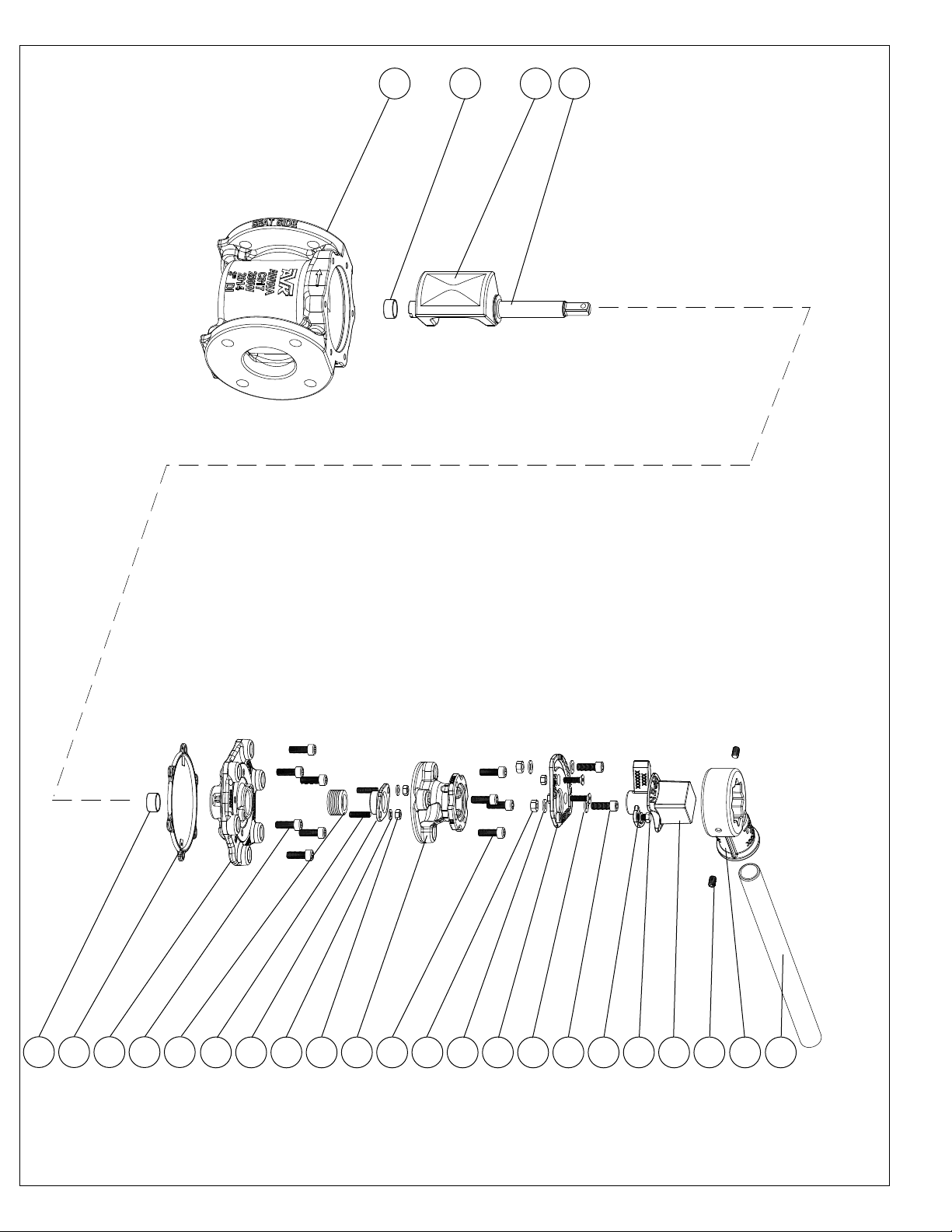
American AVK Series 764 Eccentric
Exploded Parts Breakdown
Plug Valve
714
704
703
702
709
706
708
715
707
701
702
723
722
page 1
718
722
721
725
724
726
730
728
729

Item No. Description Material
701 ISO Flange Grey iron, ASTM A126, "B"
702 Bolts NBR
703 Bonnet 304 Stainless steel
704 Chain Set Zinc Plated steel
705 Bonnet Gasket NBR
706 Body Grey iron, ASTM A126, "B"
707 Hex Nut Zinc Plate, 304,316 Stainless steel
708 Gland Ductile Iron, ASTM A536
709 V-Pack NBR
710 Plug Core Copper Alloy
711 Plug Rubber NBR
712 Thrust Washer Grey iron, ASTM A126, "B"
713 O-Ring 304 Stainless steel
714 Bearing 304 Stainless steel
715 Washer NBR, Neoprene
716 Gearbox Bolt Copper Alloy
717 Gearbox Washer NBR, Neoprene
718 Stop Plate Zinc Plate, 304,316 Stainless steel
719 Stop Plate Screw Copper Alloy
720 Stop Plate Nut NBR
721 Stop Bolt Copper Alloy
722 Stop Washer NBR
723 Stop Nut Copper Alloy
724 Wrench Nut Lock Bolt EPDM encapsulated ductile iron
725 Wrench Nut Lock Washer Copper Alloy
726 Wrench Nut Copper Alloy
727 Wrench Nut Key * 304 Stainless steel
728 Wrench Head 304 Stainless steel
729 Lever 304 Stainless steel
730 Wrench Head Screw 304 Stainless steel
731 Gearbox* 304 Stainless steel
* Not Shown
page 2

SAFETY
Make sure all relevant Health and Safety issues and regulations are adhered to prior to and during installation or
maintenance work carried out on this product. It is the end users responsibility to ensure that safe working practices are
followed at all times.
Whenever AVK’s products are installed, operated or maintained the inherent dangers of pressurized liquids and
gasses must be addressed. Before work on a valve or other piping component is undertaken, that may involve the release
of internal pressure, the valve or line must be fully isolated, depressurized and drained prior to commencing the work.
All workers handling the product must be aware of the weight of the components or assemblies to be handled and
manipulated during installation and maintenance. It is essential that staff undertaking these operations are adequately
trained and it is the responsibility of the end user that only trained and competent staff undertake these duties.
This manual has been designed to assist, but it cannot replace quality training in the workplace. However, AVK’s
technical staff are always available to answer questions relating to specic problems that may not be covered by this
manual.
AVK’s products are designed to be t for purpose and to a high reliability standard. This provides a safe, low risk
product when used correctly for the purpose for which it was designed. However, this assumes that the equipment is used
and maintained in accordance with this manual, and the user is advised to study it and to make it available to all staff that
may need to refer to it.
AVK Valves cannot be held responsible for incidents arising from incorrect installation, operation or maintenance.
The responsibility for this rests wholly with the end user.
page 3

INTRODUCTION / DESCRIPTION
AVK eccentric plug valves are designed with built-in safety in every detail. Plug valves are used for isolation purposes
in water and wastewater installations, for pump control shut-off and ow control applications. The plug is fully vulcanized
with AVK’s own rubber compound (either EPDM or NBR) which, due to its sturdy design and double bonding vulcanization,
features an outstanding durability, with the plugs rubber ability to regain its original shape. The valve has a welded nickel
seat and a full port design allowing high ow capability with minimal headloss when in the fully open position. The valve
body, bonnet and ISO mounting ange are all epoxy coated internally and externally for optimal corrosion resistance. The
valve design incorporates a unique integral ISO operator mounting ange which provides increased exibility when selecting
gearbox or electrical actuator units.
UNLOADING:
All valves should be carefully unloaded. Each valve should be carefully lowered from the truck to the ground; it should
not be dropped. Do not lift valves with slings or chain around actuator or through waterway. Lift valves with eyebolts or rods
through flange holes or chain hook at the ends of valve parts. Failure to carefully follow these recommendations is likely to
result in damage to the valve as well as risk of personal injury.
INSPECTION AFTER UNLOADING:
AVK eccentric plug valves should be inspected for damage at the time of receipt. The initial inspection should verify
compliance with specifications, direction of opening, size and flange details. A visual inspection of the seating surfaces should
be performed to detect any damage in shipment or scoring of the seating surfaces. Inspection personnel should look for any
other evidence of mishandling during shipment. Each valve should be operated through one complete opening-and-closing
cycle in the position in which it is to be installed.
STORAGE:
1. The plug valves should be stored in a manner that protects them from the environment, preferably indoors.
2. The valves should be stored with the plug in the open position to prevent unnecessary compression of the rubber
compound.
3. The plug should also be protected from sunlight, ozone and chemical exposure.
4. In colder climates, valves should be drained and left slightly open before storage. Failure to do so may result in damage
to the valve castings from water freezing.
5. Valves stored outside should be stored with the plug core in the vertical position. If the valves are stored in the horizontal
or flat position, rainwater may accumulate in the valve cavity, potentially causing damage due to water freezing
page 4

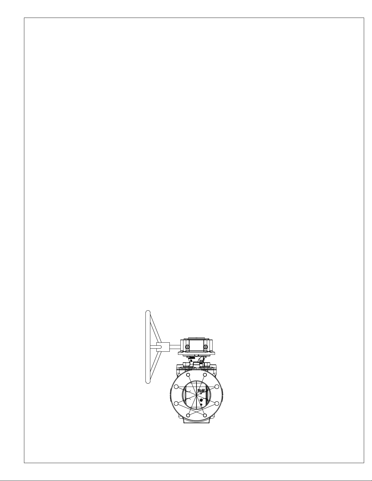
FLOW
Typical Eccentric Plug Valve
Installations
When eccentric plug valves are
mounted in a horizontal line, the
recommended installation is with
the plug rotating 90° upward to
open. This orientation reduces the
chance of solids preventing plug
operation.
Eccentric plug valves may
be installed vertically;
however, whenever
possible, horizontal
orientation is preferred.
FLOW
When installed in a vertical
line where solids may be
present, the seat should be
located in the top or upward
position, preventing solids
from accumulating in the
valve body.
FLOW
Fig. 1
Eccentric Plug Valve Installation
page 5
INSTALLATION AND TESTING
NOTE: Consult local codes and standards for valve placement and spacing
WARNING: All water lines must be isolated or depressurized and drained before installing or maintaining valves.
Failure to do so may cause pressure to be released resulting in severe injury or death.
INSPECTION PRIOR TO INSTALLATION:
1. Visually inspect each valve for any foreign material in the interior of the valve, and remove it if present.
2. Inspect each valve in a similar manner as described in the "INSPECTION AFTER UNLOADING" section of this manual.
INSTALLATION:
1. Open and close the valve to verify proper operation. Close the valve if it is going into a trench.
2. Take care when handling the valve. Use the proper lifting areas on the valve. Do not lift the valve by the actuating devices.
Do not use chains or other lifting devices through the waterway.
3. During installation there is the possibility of foreign materials inadvertently entering the valve. Foreign material can
damage the internal working parts during operation of the gate valve. For this reason, gate valves should be installed in
the closed position. Each valve should be placed on firm footing in the trench to prevent settling and excessive strain on
the connection to the pipe. Piping systems should be supported and aligned to avoid damage to the valve.
4. Valves should be installed in the proper flow direction and with adequate clearance for actuating devices. The valves are
designed o allow flow in both directions, however, they are normally installed in a "standard" flow direction with the seat on
the downstream of the flow and the flow against the back of the plug.
5. Tighten the bolts and nuts in the crossover method shown in Fig. 2, to load the pipe and valve evenly and prevent stress
on the joints.
6. Valves buried in unusually deep trenches should have special provisions for operating the valve. Either a riser on the
stem to permit use of a normal key or a notation on the valve records that a long key will be required.
7. When valves with exposed gearing or operation mechanisms are buried below ground, a vault designed to allow pipe
clearance and prevent settling on the pipe should be provided. The operating nut should be accessible from the top
opening of the vault with a valve key. The size of the vault should provide for easy removal of the valve bonnet and
internal parts of the valve for purposes of repair. Consideration should be given to the possibility of groundwater and/or
surface water and to the need to provide the disposal of such water.
8. Valves installed above ground or in a plant piping system should be supported and aligned to avoid damage to the valves.
Valves should not be used to correct the misaligned piping.
9. Do not test valve systems to greater than the rated valve pressure.
10. With the valves in the open positions, flush the entire system to prevent the valves from closing on foreign materials and
damaging the seats or plugs.
3
page 6
1
7
Fig. 2
8
45
6
2

INSTALLATION: ( cont. )
INSTALLATION: - Liquids without Suspended Solids and Clean Gases
For liquids without suspended solids and clean gas application, the plug valve can be installed for both horizontal and
vertical pipe orientations.
LIQUIDS AND GASES:
1. Before installation, remove foreign material such as weld spatter, oil, grease, and dirt from the valve and pipeline.
2. Install the valve as shown in Figure 1.
3. Ensure the valve and anges are concentric to effect proper ange sealing.
4. Tighten the ange bolts or studs in a sequence according to Figure 2.
SUSPENDED SOLIDS:
1. Before installation, remove foreign material such as weld spatter, oil, grease, and dirt from the valve and pipeline.
2. Install the valve as shown in Figure 1.
A. In horizontal pipelines install valve so plug is horizontal and rotates upward as valve opens.
B. For vertical pipelines, install valve with the end marked “Seat” at top of valve.
3. Tighten the ange bolts or studs in a sequence according to Figure 2.
4. Ensure the valve and anges are concentric to effect proper ange sealing.
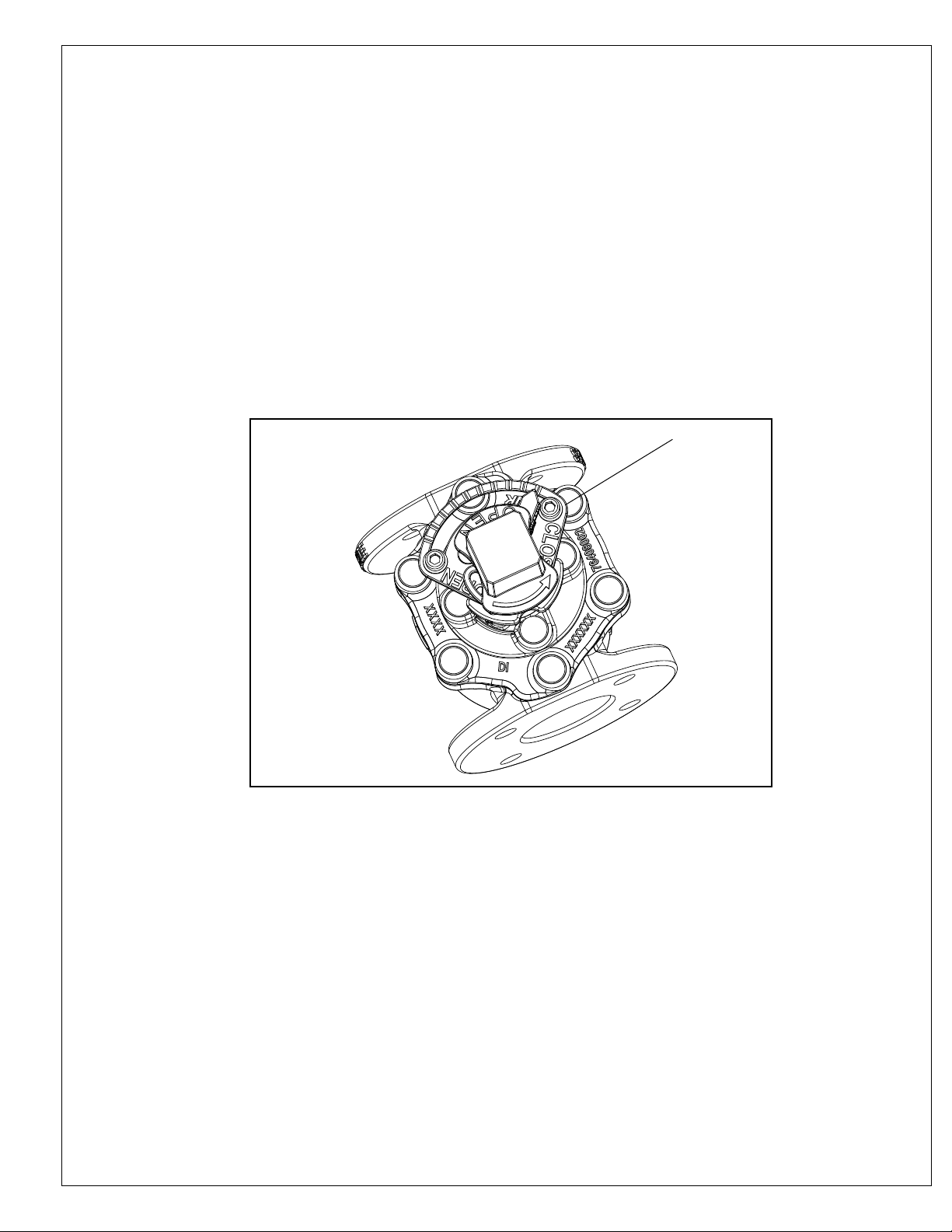
DIRECT NUT OPERATED VALVES:
S764 valves up to DN200/8” are able to operate with a top-mounted 2” square nut for ¼ turn operation and is
mounted directly to the valve plug. To open the valve, rotate the nut 90 degrees in the counter-clockwise direction and to
close the valve, rotate the nut 90 degrees in the clockwise direction. The closed/open position is adjusted by using two
screws as shown in Figure 3.
Closed
Adjustment Bolt
Open
Adjustment Bolt
Fig. 3
page 7

LEVER OPERATED VALVES:
A wrench head and lever (Figure 4) are also available for use for direct quarter-turn operation. Various lever lengths
are available for specic pressure conditions as shown in the Table below. All lengths are in accordance with EN12570
Handle
L
Wrench Head
Fig. 4
Wrench Length ( In. ) ( L )
DN
Direct pressure 7 bar/100 PSI Direct pressure 2 bar/25 PSI
DN 65-100 20 20
DN 150-200 40 40
page 8

TESTING AFTER INSTALLATION:
In order to prevent time searching for potential leaks, it is recommended that excavation should not be backlled
until after pressure tests of the pipeline system have been made. After installation, it is desirable to test newly installed
piping sections, including valves, at some pressure above the system designed pressure. The test pressure should not
exceed the rated working pressure of the valve. After the test, steps should be taken to relieve any trapped pressure in the
body of the valve. The valve should not be operated in either the opening or closing direction at differential pressures above
the rated working pressure. It is also recognized that wear or foreign material may damage valve seating surfaces and may
cause leakage.
On completion of the installation, valve location, size, make, type, date of installation, angle to open, direction of opening,
and other information deemed pertinent should be entered on permanent records.
APPLICATION HAZARDS:
1. AVK eccentric plug valves should not be installed in lines where service pressure will exceed the rated working pressure
of the valve.
2. The valve should not be used in applications that are exposed to freezing temperatures unless sufcient ow is
maintained through the valve or other protection is provided to prevent freezing.
3. Pipe, ttings, and valves installed in underground pipelines are generally joined with mechanical joints. These joints are
considered unrestrained-type joints since no considerable restraint against longitudinal separation is provided.
4. Plug valves should not be installed in a dead end or near a bend in a pipeline without proper and adequate restraint to
support the valve and prevent it from damage.
5. It is good engineering practice to consider during the design whether or not thrust blocks, restrained joints, or other
means of restraint are needed on or adjacent to valves on pipelines and/or where unusual conditions exist, such as high
internal pressures, adjacent ttings, or unsuitable soils.
6. The valve should not be used as a lifting device for pipes (or equal) mounted on the valve
page 9
OPERATION AND MAINTENANCE
OPERATION
WARNING: Flush the system prior to operating valves to prevent damage to seats and plugs.
1. Do not operate the valves in a system that exceed the valves rated working pressure of 250 PSI.
2. AVK Eccentric Plug Valves are "Open Left" or counter-clockwise to open, quarter turn or 90 degrees to open or close.
3. Manually actuated valves have mechanical stops for the open and closed positions that are clearly marked on the Stop
Plate (F718). There are also detents in the Stop Plate (F718), if valve throttling is desired. ( See Fig. 5 )
4. For valves with gearboxes, the number of turns to open and close are as follows:
2½", 3", and 4" - 8.5 turns
6" - 9.5 turns
8" - 12 turns
10" and 12" - 24 turns
5. Valve operation and cycling should be scheduled more frequently for systems that have higher solid contents in the water.
6. Never force the valve to seat. Re-open the valve and ush the system again to verify that debris has been dislodged from
the seating area.
F718
Fig. 5
Stop Plate Detail
MAINTENANCE
WARNING: Flush the system prior to operating valves to prevent damage to seats and plugs. When performing
maintenance that requires disassembly on valves, ensure that the system pressure is at 0 PSI.
1. AVK Eccentric Plug Valves are designed to be relatively maintenance free. Do not disassemble valves unless an
interruption to normal service has occurred in the system.
2. Periodic lubrication is not required. Lubrication is only required if disassembly/reassembly of the valve is performed.
3. Regular functional inspections should be performed at a minimum of twice a year. When performing a functional
inspection, operate the valves under normal working pressure, making sure they operate normally without any vibrations.
4. For valves with gearboxes, refer to the gearbox manufacturer's maintenance procedures.
5. Proper records should be maintained for all maintenance procedures and schedules.
page 10

REPAIR PROCEDURES
Leakage, broken parts, hard operation, and other major defects should be corrected by a repair crew as soon as
possible after the defect has been reported. If repairs are to be performed in the eld, the repair crews should take a full
complement of spare parts to the jobsite. Provisions should be made to isolate the defective valve from water pressure
and relieve internal trapped pressure prior to performing any corrective maintenance. Disassembly of the valve should be
accomplished in accordance with the procedure supplied in the following sections. After repairing the valve, the operating
mechanism should be cycled through one complete operating cycle. With full line pressure applied to the valve in the open
position, an inspection should be made to detect leakage in the areas around the seat, bonnet, packing/stem, and body-end
connections. A record should be made to indicate that the valve has been repaired and is in working condition. Any marking
that the valve is inoperable should be removed. In addition, re department and other appropriate municipal departments
should be informed of satisfactory repair of the valve.
PACKING ADJUSTMENT
1. This can be carried out with the valve under pressure in the pipeline.
2. Tighten the two gland nuts (4) on gland (8) to stop the leakage
3. If the leakage continues, the packing should be replaced.
PACKING REPLACEMENT
Need a packing replacement without removing the actuator and top plate. Valmatic does it by cutting the packing.
1. Isolate the valve and depressurize the line.
2. Remove hot melt (1) to expose ISO ange bolts (2)
3. Remove actuator.
4. Remove ISO ange(3) with bolts (2)
5. Remove gland (8) & gland nuts(4) & washers(6) and replace packing (9)
6. Put gland (8) and tighten the gland nuts (4) to press packing (9) until no leakage
7. Put ISO ange (3) and tighten the ISO ange bolts (2) ( 4xthread size=req. Nm, See table )
8. Install actuator.
Valve Size Torque Ft. Lbs.
2 1/2" - 3" 30
4" - 6" 35
8" 50
10" -12" 60
page 11

REPLACE BONNET GASKET: (FIGURE 6)
1. Isolate valve and ensure there is no pressure in pipeline
2. Remove hot melt (1) to expose bonnet bolts (2)
3. Remove actuator
4. Disassembly ISO ange (3) , gland (8) & gland nuts (4) and packing (9)
5. Remove bonnet bolts (2) and lift bonnet (10)
6. Replace bonnet gasket (11) then reassemble bonnet (10) and tighten bonnet bolts (2) (4xthread = req. Nm , See table.).
7. Put packing (9) , gland (8), washers (6) and tighten the gland nuts (4) to press packing (9) until no leakage
8. Put ISO ange (3) and tighten the ISO ange bolts (2) ( 4xthread size=req. Nm, See table )
9. Install actuator
REPLACE OTHER COMPONENTS: (FIGURE 7)
1. Isolate valve and ensure there is no pressure in pipeline
2. Remove hot melt (1) to expose bonnet bolts (2)
3. Remove actuator
4. Disassembly ISO ange (3) , gland (8) & gland nuts (4) and packing (9)
5. Remove bonnet bolts (2) and lift bonnet (10)
6. Push plug (15) out of body (17), replace needed components then reassemble
7. Put assembly of plug , gasket , bonnet (10) and tighten bonnet bolts (2) (4xthread = req. Nm, See table)
8. Put packing (9) , gland (8), washers (6) and tighten the gland nuts (4) to press packing (9) until no leakage
9. Put ISO ange (3) and tighten the ISO ange bolts (2) ( 4xthread size=req. Nm, See table )
10. Install actuator
page 12

TROUBLESHOOTING GUIDE
PROBLEM: Hydrant leaking from around nozzle.
Probable Cause: Damaged valve disc or nozzle sealing surface.
Corrective action: Inspect valve disc and nozzle sealing surfaces and replace if necessary.
PROBLEM: Hydrant leaking from around stem nut.
Probable Cause: Damaged stem o-rings.
Corrective action: Replace stem o-rings.
PROBLEM: Nozzle section facing the wrong direction.
Corrective action: Loosen the Nozzle Section hardware and carefully rotate the Nozzle Section to the desired
position. Tighten the mounting hardware to 60 Ft. Lbs..
PROBLEM: Hydrant ow is low.
Probable Cause: Hydrant or supply vale is not fully open.
Corrective action: Verify that the hydrant is fully open. The AVK Series 24 hydrant valve discs are fully opened
in approximately 9-14 turns.
Also locate and verify that the supply valve is fully open.
page 13

PARTS AND SERVICE
For information on parts and service for your area contact American AVK. Make a note of the hydrant model number and size
located on the hydrant and contact:
American AVK Company
2155 N. Meridian Blvd.
Minden, NV 89423
PH: 775-552-1400
FAX: 775-783-7502
www.americanavk.com
AMERICAN AVK COMPANY WARRANTY
SERIES 24 WET BARREL HYDRANTS
American AVK Company warrants all models of Series 24 Wet Barrel Fire Hydrants to be free from defects in workmanship
and materials for a period of ten (10) years from the date of shipment from American AVK Company. American AVK Company
shall have no obligation under this warranty unless it is notied of claims hereunder promptly and in writing upon discovery
thereof and within the warranty period, and unless the product is delivered to an American AVK Company facility within thirty
(30) days of such notice.
American AVK shall have the right to inspect said product before it is removed from installation. If the product is removed from
installation prior to approval from American AVK this warranty shall be void.
As to motors, gearing or accessory equipment purchased by American AVK Company from others manufacturers, and used
or incorporated into American AVK Company’s products, those manufacturers’ warranties shall apply.
American AVK Company will honor all reasonable costs to repair or replace any American AVK Company Wet Barrel Fire
Hydrant found to be defective.
American AVK Company's sole responsibility shall be, in its sole discretion, to replace the product with the same or a similar
product, repair the product, or refund the price paid for the product provided the product has been properly applied and used
under normal service and under conditions for which it is designed. American AVK Company shall not be liable for indirect,
special, incidental, or consequential damage or penalties and does not assume any liability of purchase to others or to anyone
for injury to persons or property.
THIS IS THE EXCLUSIVE WARRANTY GIVEN IN CONNECTION WITH THE SALE OF THIS PRODUCT. THERE ARE
NO OTHER WARRANTIES, EXPRESSED OR IMPLIED, INCLUDING EXPRESSED OR IMPLIED WARRANTY OF
MERCHANTABILITY, OR ANY EXPRESSED OR IMPLIED WARRANTY OF SUITABILITY FOR ANY PARTICULAR
PURPOSE, GIVEN BY AMERICAN AVK COMPANY IN CONNECTION WITH THIS PRODUCT.
page 14
 Loading...