

Page 1
User Manual
Sequoia UHD / UHD+ / UHD/T / UHD/T+
Simplified UHD Multi-viewer Solution for Multiple Computer and Video
System
Revision 1.0.1, (April, 2018)
Page 2

User Manual
ABOUT THIS MANUAL
This manual contains information on how to use the Avitech Sequoia UHD / UHD+ / UHD/T / UHD/T+ keyboard
mouse controller. There are six chapters in this manual.
Getting Started introduces features and specifications as well as external components of the Avitech Sequoia
UHD / UHD+ / UHD/T / UHD/T+.
System Configuration discusses the process of setting up your Sequoia UHD / UHD+ / UHD/T / UHD/T+.
Basic Operations introduces the two types of operating modes and demonstrates the keyboard and mouse
hot-keys to perform basic operations, as well as using the on-screen pop-up menu to configure your Sequoia
UHD / UHD+ / UHD/T / UHD/T+.
Using the Mouse Right-click Menu, Changing the Background Image and Salvo discusses display and
feature settings for the Sequoia UHD / UHD+ / UHD/T / UHD/T+ such as customization of the user interface,
presets save/load, alarm setup, audio routing, file transfer, and hot-key hint. It also touches on setting the
background image of the preview area of the in-system GUI as well as configure salvo to map sources and
destinations (routings).
Video Wall Management provides the steps necessary to setup 1×1 and 2×2 and 2×3 and 3×4 wall display.
Using the Touch-screen discusses the process of using the touch-screen feature.
The following conventions are used to distinguish elements of text throughout the manual.
provides additional hints or information that require special attention.
identifies warnings which must be strictly followed.
Any name of a menu, command, icon or button displayed on the screen is shown in a bold typeset.
For example: On the Start menu select Settings.
Any name that refers to a mode is underlined.
For example: Windows can be adjusted by the Host cursor when the Sequoia UHD / UHD+ / UHD/T / UHD/T+ are in
Host mode.
To assist us in making improvements to this user manual, we welcome any comments and constructive criticism.
Please email us at: sales@avitechvideo.com.
CAUTION
RISK OF EXPLOSION IF BATTERY IS REPLACED
BY AN INCORRECT TYPE.
DISPOSE OF USED BATTERIES ACCORDING
TO THE INSTRUCTIONS.
Do not attempt to disassemble the Sequoia UHD / UHD+ / UHD/T / UHD/T+. Doing so may void the warranty. There
are no serviceable parts inside. Please refer all servicing to qualified personnel.
WARNING
Hazardous moving parts
Keep away from moving fan blades
TRADEMARKS
All brand and product names are trademarks or registered trademarks of their respective companies.
COPYRIGHT
The information in this manual is subject to change without prior notice. No part of this document may be
reproduced or transmitted in any form or by any means, electronic or mechanical for any purpose, without the
express written permission of Avitech International Corporation. Avitech International Corporation may have
patents, patent applications, trademarks, copyrights or other intellectual property rights covering the subject matter
in this document. Except as expressly written by Avitech International Corporation, the furnishing of this document
does not provide any license to patents, trademarks, copyrights or other intellectual property of Avitech International
Corporation or any of its affiliates.
TECHNICAL SUPPORT
For any questions regarding the information provided in this guide, call our technical support help line at
425-885-3863, or our toll free help line at 1-877-AVI-TECH, or email us at: support@avitechvideo.com.
ii
Page 3

Contents
About This Manual ....................................................................................................................... ii
Trademarks ................................................................................................................................... ii
Copyright ...................................................................................................................................... ii
Technical Support ........................................................................................................................ ii
Warranty ...................................................................................................................................... vii
Limitation of Liability ................................................................................................................. vii
Extended Warranty Options ...................................................................................................... vii
Services and Repairs Outside the Warranty Period ............................................................... vii
Regulatory Information .............................................................................................................. vii
Federal Communications Commission (FCC) Statement ...................................................... vii
European Union CE Marking and Compliance Notices ......................................................... vii
Australia and New Zealand C-Tick Marking and Compliance Notice ................................... vii
1. Getting Started ............................................................................................................ 1
1.1 Package Contents ................................................................................................................. 2
1.2 Product Features .................................................................................................................. 3
1.3 Specifications ....................................................................................................................... 4
1.4 Connections to the Sequoia UHD / UHD+ / UHD/T / UHD/T+ ............................................ 6
2. System Configuration ............................................................................................... 11
2.1 Installing a New Module on a Blank Slot .......................................................................... 11
2.2 Removing a Previously Installed Module ......................................................................... 12
2.3 Getting the Sequoia UHD Ready ....................................................................................... 14
2.3.1 Basic Setup ............................................................................................................... 14
2.3.2 Sequoia UHD/T with Pacific X-IPT / X-IPTR (RX) / X-IPRW / X-IPRG
Connected via Gigabit IGMP Switch ...................................................................... 16
Connections to the Pacific X-IPT ......................................................................................... 17
Connections to the Sequoia UHD/T ..................................................................................... 17
Connections to the Pacific X-IPTR (RX) and Pacific X-IPRW Workstation ....................... 18
Connections to the Pacific X-IPTR (RX) .............................................................................. 19
Connections to the Pacific X-IPRG ...................................................................................... 20
Powering Up the Devices ..................................................................................................... 20
Configuring the Pacific X-IPRG ........................................................................................... 20
Configuring the Pacific X-IPT ............................................................................................... 21
Configuring the Pacific X-IPTR Workstation ...................................................................... 22
Configuring the Pacific X-IPTR ............................................................................................ 23
Configuring the Pacific X-IPRW ........................................................................................... 23
Configuring the Sequoia UHD/T........................................................................................... 23
Routing TX to RX................................................................................................................... 24
EDID Read .............................................................................................................................. 24
Sequoia UHD “Surfer” Mode Limitation ................................ ................................ .............. 24
iii
Page 4

2.3.3 Sequoia UHD to 2×2 Video Wall with Pacific X-IPT Connected via Gigabit
IGMP Switch ............................................................................................................. 26
Connections to the Pacific X-IPT ......................................................................................... 27
Connections to the Sequoia UHD ........................................................................................ 28
Powering Up the Devices ..................................................................................................... 29
Configuring the Pacific X-IPT ............................................................................................... 29
Configuring the Sequoia UHD .............................................................................................. 31
Routing TX to RX................................................................................................................... 31
2.3.4 Two Sequoia UHD/T+ to 2×3 Video Wall with Two Pacific X-IPT Connected
via Gigabit IGMP Switch .......................................................................................... 32
Connections to the Two Pacific X-IPT ................................................................................. 33
Connections of the Two Sequoia UHD+ Connect to Wall Display .................................... 33
On the Sequoia UHD+ 1 ........................................................................................................ 34
On the Sequoia UHD+ 2 ........................................................................................................ 34
Connections to the Controlling Sequoia UHD/T+ ............................................................... 34
Powering Up the Devices ..................................................................................................... 35
Configuring the Two Pacific X-IPT....................................................................................... 35
Configuring the Controlling Sequoia UHD/T+ as well as Sequoia UHD+ 1 and 2 ............ 37
Routing TX to RX................................................................................................................... 37
3. Basic Operations ...................................................................................................... 38
Host Mode .............................................................................................................................. 38
Remote Mode ........................................................................................................................ 38
Tips on Navigating the Sequoia UHD .................................................................................. 38
3.1 Host Mode ........................................................................................................................... 39
3.1.1 Pop-up Selections .................................................................................................... 39
3.1.2 Functions (multiview display) ................................................................................. 39
3.1.3 Hot-keys .................................................................................................................... 40
3.2 Remote Mode ...................................................................................................................... 41
4. Using the Mouse Right-click Menu, Changing the Background Image and Salvo 43
4.1 Mouse Right-click Menu..................................................................................................... 43
Layout preset ........................................................................................................................ 44
Save preset ............................................................................................................................ 44
Load preset ............................................................................................................................ 44
Delete preset by name .......................................................................................................... 45
Display ................................................................................................................................... 45
Change output resolution .................................................................................................... 45
Keep aspect ratio .................................................................................................................. 45
Flip .......................................................................................................................................... 45
Display mode ......................................................................................................................... 45
Display mode background color.......................................................................................... 45
Label ....................................................................................................................................... 46
Display label .......................................................................................................................... 46
Display IP UMD ...................................................................................................................... 46
iv
Page 5

Define label ............................................................................................................................ 46
Label outside video ............................................................................................................... 47
Blending ................................................................................................................................. 47
Label auto-hide...................................................................................................................... 47
Display label when full screen ............................................................................................. 47
Border .................................................................................................................................... 47
Border color .......................................................................................................................... 47
Border width .......................................................................................................................... 48
Active window border ........................................................................................................... 48
Display active window border .............................................................................................. 48
Active window border color (Surfer mode) / (Normal mode) ............................................ 48
Video alarm ............................................................................................................................ 49
Display signal format ............................................................................................................ 49
Display signal format ............................................................................................................ 49
Signal format auto-hide ........................................................................................................ 49
Blending ................................................................................................................................. 49
Tally ........................................................................................................................................ 49
HDMI tally color ..................................................................................................................... 49
Headphone tally color ........................................................................................................... 50
Full screen control ................................................................................................................ 51
Automatically enter Remote mode ...................................................................................... 51
Apply previous layout upon leaving Remote mode ........................................................... 51
Fading level ........................................................................................................................... 51
Audio routing ........................................................................................................................ 52
Marquee ................................................................................................................................. 54
Window drag/resize preview frame ..................................................................................... 56
Show IP TX/RX list ................................................................................................................ 56
Show IP salvo list .................................................................................................................. 60
IP card setup ......................................................................................................................... 60
Video wall management ....................................................................................................... 60
File transfer ........................................................................................................................... 60
Set copy file via USB ............................................................................................................ 60
Terminate copy file ............................................................................................................... 60
System ................................................................................................................................... 60
Network .................................................................................................................................. 61
Power / Fan / Thermal alarm ................................................................................................ 62
Export to USB disk ................................................................................................................ 62
Language ............................................................................................................................... 63
USB device path .................................................................................................................... 63
Mouse setup .......................................................................................................................... 63
KM assign .............................................................................................................................. 63
Reset factory defaults ........................................................................................................... 63
Read EDID from screen ........................................................................................................ 63
v
Page 6

Firmware version .................................................................................................................. 64
Hot-key overview................................................................................................................... 64
4.2 Changing the Background Image ..................................................................................... 64
4.3 Salvo .................................................................................................................................... 66
4.3.1 Configure a Salvo .................................................................................................... 66
5. Video Wall Management ........................................................................................... 69
5.1 Basic Video Wall Management Setup ............................................................................... 69
Set Genlock Source .............................................................................................................. 76
5.2 Additional Adjustments For 1×1 Wall Display ................................................................. 89
6. Using the Touch-screen ........................................................................................... 98
Host Mode .............................................................................................................................. 98
Remote Mode ........................................................................................................................ 98
Tips on Navigating the Touch-screen Monitor Using the Sequoia UHD / UHD/T ............ 98
6.1 Pop-up Selections .............................................................................................................. 99
6.1.2 Functions (multiview display) ................................................................................. 99
6.2 Drop-down Auto-hide Menu ............................................................................................ 100
6.3 Lock/Unlock Window Layout ........................................................................................... 101
6.4 Audio Controls .................................................................................................................. 102
6.5 Move/Resize/Close Window ............................................................................................ 103
6.6 Exit from Remote Operation Mode to Host Operation Mode ....................................... 103
6.7 Switch Control (Cycle) Between Full Screen Windows ................................................ 104
Appendix A Using the GO! Bridge Utility .................................................................. 106
Appendix B Using the “Surfer” Feature .................................................................... 113
B.1 “Surfer” Feature on Uniform Quad Layout That Fills Entire Screen ........................... 114
B.2 “Surfer” Feature on Non-adjoining Quad Layout .......................................................... 116
B.3 “Surfer” Feature on Full Screen “Image” Window ........................................................ 116
B.3.1 “Image” Window Control Switching .................................................................... 116
B.3.2 Monitor Control Switching (Dual Display Setup) ................................................ 117
Appendix C Using the Auto-hide Menu ..................................................................... 118
Appendix D Resetting to the Factory-Default State .................................................. 119
vi
Page 7

Warranty
Avitech International Corporation (herein after referred to as “Avitech”)
warrants to the original purchaser of the products manufactured in its
facility (the “Product”), that these products will be free from defects in
material and workmanship for a period of 1 year or 15 months from the
date of shipment of the Product to the purchaser. There is a 3 month
grace period between shipping and installation.
If the Product proves to be defective during the 1 year warranty period,
the purchaser’s exclusive remedy and Avitech’s sole obligation under
this warranty is expressly limited, at Avitech’s sole option, to:
(a) repairing the defective Product without charge for parts and labor;
or (b) providing a replacement in exchange for the defective Product;
or (c) if after a reasonable time is unable to correct the defect or
provide a replacement Product in good working order, then the
purchaser shall be entitled to recover damages subject to the limitation
of liability set forth below.
Limitation of Liability
Avitech’s liability under this warranty shall not exceed the purchase
price paid for the defective product. In no event shall Avitech be liable
for any incidental, special, or consequential damages, including
without limitation, loss of profits for any breach of this warranty.
If Avitech replaces the defective Product with a replacement Product
as provided under the terms of this Warranty, in no event will the term
of the warranty on the replacement Product exceed the number of
months remaining on the warranty covering the defective Product.
Equipment manufactured by other suppliers and supplied by Avitech
carries the respective manufacturer’s warranty. Avitech assumes no
warranty responsibility either expressed or implied for equipment
manufactured by others and supplied by Avitech.
This Warranty is in lieu of all other warranties expressed or implied,
including without limitation, any implied warranty of merchantability or
fitness for a particular purpose, all of which are expressly disclaimed.
This Hardware Warranty shall not apply to any defect, failure, or
damage: (a) caused by improper use of the Product or inadequate
maintenance and care of the Product; (b) resulting from attempts by
other than Avitech representatives to install, repair, or service the
Product; (c) caused by installation of the Product in a hostile operating
environment or connection of the Product to incompatible equipment;
or (d) caused by the modification of the Product or integration with
other products when the effect of such modification or integration
increases the time or difficulties of servicing the Product.
Any Product which fails under conditions other than those specifically
covered by the Hardware Warranty, will be repaired at the price of
parts and labor in effect at the time of repair. Such repairs are
warranted for a period of 90 days from date of reshipment to customer.
Extended Warranty Options
Avitech offers OPTIONAL Extended Warranty plans that provide
continuous coverage for the Product after the expiration of the
Warranty Period. Contact an Avitech sales representative for details
on the options that are available for the Avitech equipment.
Services and Repairs Outside the Warranty Period
Avitech makes its best offer to repair a product that is outside the
warranty period, provided the product has not reached its end of life
(EOL). The minimum charge for such repair excluding shipping and
handling is $200 (US dollars).
AVITECH INTERNATIONAL CORPORATION
● 15377 NE 90th Street Redmond, WA 98052 USA
● TOLL FREE 1 877 AVITECH
● PHONE 1 425 885 3863
● FAX 1 425 885 4726
● info@avitechvideo.com
● http://avitechvideo.com
Regulatory Information
Marking labels located on the exterior of the device indicate the
regulations that the model complies with. Please check the marking
labels on the device and refer to the corresponding statements in this
chapter. Some notices apply to specific models only.
Federal Communications Commission (FCC) Statement
This equipment has been tested and found to comply with the limits for
a Class B digital device, pursuant to Part 15 of the FCC Rules. These
limits are designed to provide reasonable protection against harmful
interference when the equipment is operated in a commercial
environment. This equipment generates, uses, and can radiate radio
frequency energy and, if not installed and used in accordance with the
instruction manual, may cause harmful interference to radio
communications. Operation of this equipment in a residential area is
likely to cause harmful interference, in which case the user will be
required to correct the interference at his own expense. Properly
shielded and grounded cables and connectors must be used in order
to meet FCC emission limits. Avitech is not responsible for any radio or
television interference caused by using other than recommended
cables and connectors or by unauthorized changes or modifications to
this equipment. Unauthorized changes or modifications could void the
user's authority to operate the equipment. Operation is subject to the
following two conditions: (1) this device may not cause harmful
interference, and (2) this device must accept any interference
received, including interference that may cause undesired operation.
European Union CE Marking and Compliance Notices
Statements of Compliance
English
This product follows the provisions of the European Directive
1999/5/EC.
Dansk (Danish)
Dette produkt er i overensstemmelse med det europæiske direktiv
1999/5/EC.
Nederlands (Dutch)
Dit product is in navolging van de bepalingen van Europees Directief
1999/5/EC.
Suomi (Finnish)
Tämä tuote noudattaa EU-direktiivin 1999/5/EC määräyksiä.
Français (French)
Ce produit est conforme aux exigences de la Directive Européenne
1999/5/EC.
Deutsch (German)
Dieses Produkt entspricht den Bestimmungen der Europäischen
Richtlinie 1999/5/EC.
Ελληνικά (Greek)
To προϊόν αυτό πληροί τις προβλέψεις της Ευρωπαϊκής Οδηγίας
1999/5/EC.
Íslenska (Icelandic)
Þessi vara stenst reglugerð Evrópska Efnahags Bandalagsins númer
1999/5/EC.
Italiano (Italian)
Questo prodotto è conforme alla Direttiva Europea 1999/5/EC.
Norsk (Norwegian)
Dette produktet er i henhold til bestemmelsene i det europeiske
direktivet 1999/5/EC.
Português (Portuguese)
Este produto cumpre com as normas da Diretiva Européia 1999/5/EC.
Español (Spanish)
Este producto cumple con las normas del Directivo Europeo
1999/5/EC.
Svenska (Swedish)
Denna produkt har tillverkats i enlighet med EG-direktiv 1999/5/EC.
Australia and New Zealand C-Tick Marking and
Compliance Notice
Statement of Compliance
This product complies with Australia and New Zealand's standards for
radio interference.
vii
Page 8

The information appearing in this manual applies to Sequoia UHD / UHD+ / UHD/T / UHD/T+, as well as the
IP receiver modules (Sequoia UHD-IPc / UHD-IPf), UHD to HD converter module (Sequoia UHD2HD) and
the KM card (Sequoia UHD-KM)), which can be ordered to create highly customized systems. All of the
Sequoia series add-on cards are compatible with either of the Sequoia UHD models.
To get the best results from Sequoia UHD, we recommend the following:
When using your mouse with a 4K display, select a mouse that has a 2000 dpi setting.
In industrial environments, use shielded Ethernet cables (shielded Ethernet cables are often marked
F/UTP or FTP).
1. Getting Started
The Avitech Sequoia UHD is a highly innovative device that comes with its own embedded operating
system and graphic engines. The Sequoia UHD integrates functions of a KVM (keyboard video mouse)
switch and a robust multi-viewer into one enclosure, providing a simple multi-viewing solution for any
user who works in an environment with multiple computer and video systems. With a single Sequoia
UHD being able to connect up to four-plus-one computers and instantly switch inputs among them,
users can monitor and remotely control any four computers at the same time on a single display plus a
fifth computer on a full-screen display with just one set of keyboard and mouse. With the added option of
IP-based remote control, this ensures intuitive user experience at the router’s destination over an
extended distance from source devices, and allowing streamlined access to a bank of computers by a
single keyboard/mouse. The Sequoia UHD also supports a variety of video formats from HDMI to DVI-D.
With the SUHD-IP module installed in your Sequoia UHD, intuitive signal switching and routing can be
achieved through the in-system GUI. The IP TX/RX list panels provide full configurations for switching/
routing of video signals. User can freely switch a detected TX source to any of the four built-in RX ports
in the SUHD-IP module, or route a TX source to any of the detected Avitech RX devices in the same
network mask through the IP TX/RX list panels, performing centralized management over all connected
devices.
The Sequoia UHD features an on-screen pop-up selection plus mouse right-click menu that allows
handy operation and control of the device. By clicking the relevant pop-up selections’ icon or pressing
the hot-keys through the keyboard, users can easily convert monitoring styles to various layouts, and
adjust windows to any size and position on the display. The mouse right-click menu allows users to
freely set up or configure numerous features for different applications; including audio source routing.
In addition to its interface and features, the Sequoia UHD can enter Remote mode to transfer keyboard
and mouse control from the Sequoia to the connected computer systems. Users can then remotely
control any of the connected computers with the set of keyboard and mouse on the Sequoia. The
“Surfer” feature, along with other user-friendly commands supported by the Sequoia UHD allows users
to freely switch control between the computers and the host Sequoia in an intuitive manner.
This chapter will continue to introduce more features and specifications as well as external components
of your Sequoia UHD / UHD+ / UHD/T / UHD/T+.
1
Page 9
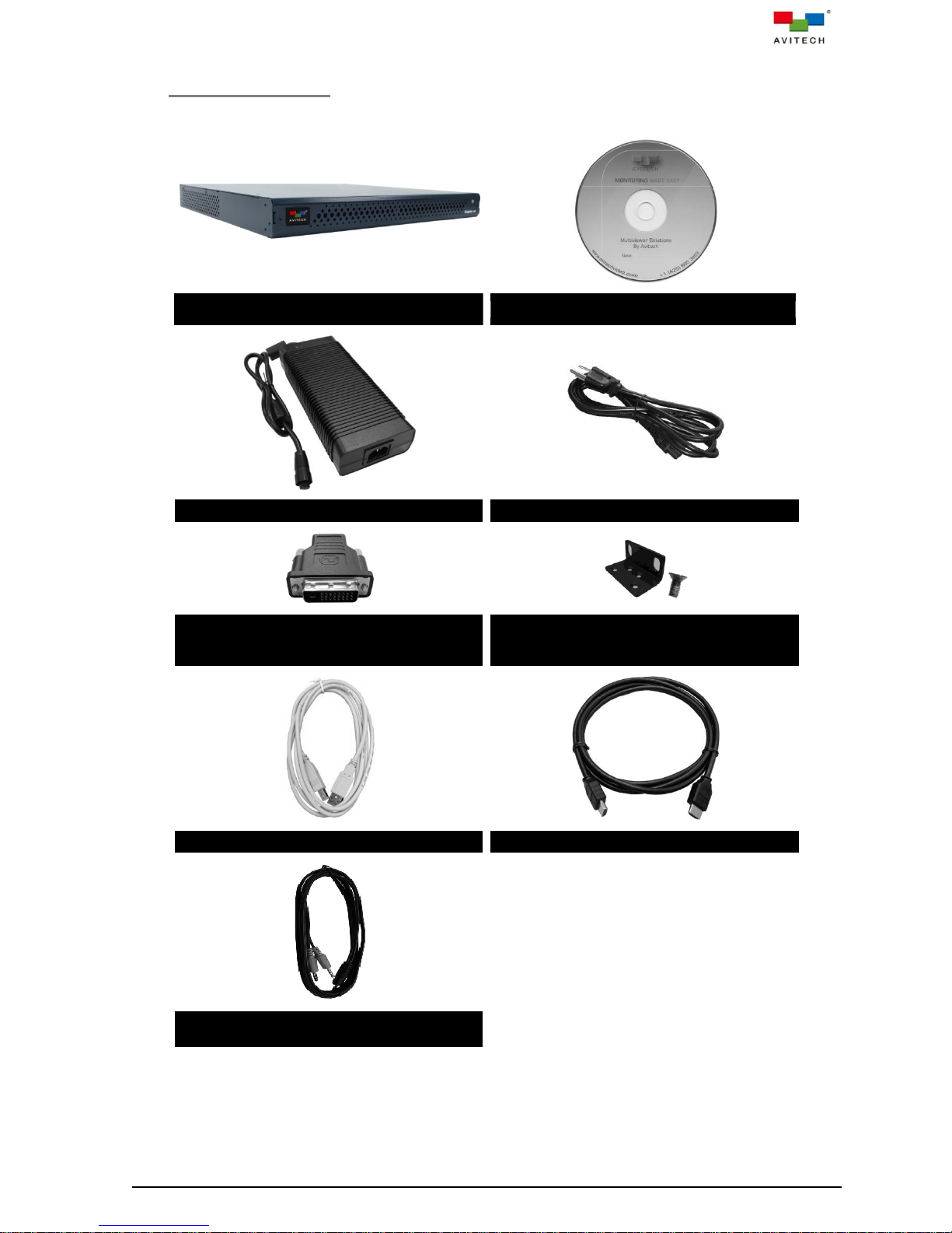
1.1 Package Contents
Avitech Sequoia UHD / UHD+ /
UHD/T / UHD/T+
Utility Disc (user manual)
12 V DC Power Adapter (optional)
Standard Power Cord (USA customer only)
HDMI to DVI Adapter (optional)
Ear with Screw
(installed on Sequoia UHD upon order for
assembly on to rack mount)
USB A/B Cable (length 1.8 m – optional)
HDMI® Cable (length 1.8 m – optional)
Male to Dual Male Y Splitter Audio Cable
(length 1.8 m – optional)
D
The following standard items are included in the shipping package:
Table 1-1 Package Contents
2
Page 10

Model
KM Module
IP Module
UHD2HD Converter
Module
Cascadable
REF I/O
IP Transmitter
Sequoia UHD
Optional
Optional
Optional
N/A
N/A
N/A
Sequoia
UHD+
Optional
Optional
Optional
√
BNC (2)
N/A
Sequoia
UHD/T
Optional
Optional
Optional
N/A
N/A
CAT-5e/6 /
SFP
Sequoia
UHD/T+
Optional
Optional
Optional
√
BNC (2)
CAT-5e/6 /
SFP
What is a window?
A window is a container for an input source. You can have multiple windows playing the same source. You
can resize and move windows in the user interface.
The maximum number of Sequoia UHD chassis that can be cascaded may be limited only by the minimum
Image size that user deems acceptable in the monitor display.
1.2 Product Features
Table 1-2 Sequoia UHD Series Comparison
The Sequoia UHD is HDCP-compliant and capable of handling HDMI® and DVI-D inputs. Featuring four
HDMI input ports, and one HDMI output port, a single Sequoia UHD can connect up to four-plus-one
computers, four videos, or any combination of four inputs. It can simultaneously display four inputs on a
single display, and allows instant switching of inputs through its OSD.
The Sequoia UHD features automatic sensing of input signals, automatic detection and selection of
optimum display resolution; it also supports hot-swapping which allows addition and removal of any
input/output signals without powering down the device. Genlock capability supports synchronizing
multiviewer outputs to the reference signal and the rest of studio/production equipment.
For audio monitoring of the four remote computers, the Sequoia UHD features four 1/8 inch headphone
jack via the proprietary Sequoia male to dual male Y splitter audio cable. It also allows monitoring of the
fifth computer on another 1/8 inch headphone jack via the proprietary Sequoia male to dual male Y
splitter audio cable. It accepts embedded HDMI® audio (8ch-stereo). Instant switching of audio signal
source for audio routing including “mix” and “mute” is available through the right-click menu.
For operation, Sequoia UHD provides convenient on-screen pop-up selections
and right-click menu as well as easy to recall hot-keys that can be controlled by a set of keyboard and
mouse, allowing free switching of operating modes and adjustments for numerous behavior that suits
different applications.
In addition to monitoring, the Sequoia UHD can remotely control the connected computers through the
USB keyboard and mouse connected to its rear panel. Utilizing the “Surfer” feature – which allows users
to transfer keyboard and mouse control from one computer to another by simply moving the mouse
cursor to the window border of the targeted computer, the Sequoia UHD is able to seamlessly switch
between and control any of the four-plus-one computers connected to it with just one set of keyboard
and mouse. Up to two IP cards (SUHD-IP) used in conjunction with Avitech’s Pacific extenders allows
sources to be installed out-of-sight at central, air-conditioned equipment rack and accessed remotely.
The Sequoia UHD is also extremely scalable; users can easily expand the system by cascading up to 25
chassis which allows for the monitoring of up to 100 signal sources on multiple screens.
Integrated file and folder transfer across computers provides convenient file management. By selecting
an origin and a destination through the onscreen user interface, the Sequoia UHD allows simple copy/
cut and paste of files/folders across connected computers using its embedded file managing tool (Go!
Bridge Utility).
3
Page 11

1. Non-standard keyboards (i.e. keyboards with a USB hub, keyboards that need driver installation and
programmable keyboards, etc.) are not supported.
2. Compatibility between the computer and the Sequoia UHD may depend on the computer’s BIOS Setup.
If an incompatibility occurs, refer to the computer’s BIOS Setup and make sure USB port is enabled if this
item exists in the computer’s BIOS Setup (typically found in the "Advanced" or "Onboard Device
Configuration" menu).
Supported HDMI /
DVI-D Input Format
Supported HDMI Output Format
4096×2160p
25Hz
4096×2160p
30Hz
3840×2160p
25Hz
3840×2160p
30Hz
1920×1080p
50Hz
1920×1080p
60Hz
3840×2160p 30Hz
√ √ √ √ √
√
3840×2160p 29.97Hz
√ √ √ √ √
√
3840×2160p 25Hz
√ √ √ √ √
√
3840×2160p 24Hz
√ √ √ √ √
√
2048×2048p 56.57Hz
√ √ √ √ √
√
1920×1200 60Hz
(Reduced Blanking)
√ √ √ √ √
√
1920×1200 50Hz
(Reduced Blanking)
√ √ √ √ √
√
1920×1080p 60Hz
√ √ √ √ √
√
1920×1080p 59.94Hz
√ √ √ √ √
√
1920×1080p 50Hz
√ √ √ √ √
√
1920×1080p 30Hz
√ √ √ √ √
√
1920×1080p 29.97Hz
√ √ √ √ √
√
1920×1080p 25Hz
√ √ √ √ √
√
1920×1080p 24Hz
√ √ √ √ √
√
1920×1080p 23.97Hz
√ √ √ √ √
√
1920×1080i 60Hz
√ √ √ √ √
√
1920×1080i 59.94Hz
√ √ √ √ √
√
1920×1080i 50Hz
√ √ √ √ √
√
1680×1050 60Hz
√ √ √ √ √
√
1680×1050 50Hz
√ √ √ √ √
√
1600×1200 60Hz
√ √ √ √ √
√
1600×1200 50Hz
√ √ √ √ √
√
1440×900 60Hz
√ √ √ √ √
√
1440×900 50Hz
√ √ √ √ √
√
1400×1050 60Hz
√ √ √ √ √
√
1400×1050 50Hz
√ √ √ √ √
√
1366×768 60Hz
√ √ √ √ √
√
1366×768 50Hz
√ √ √ √ √
√
1360×768 60Hz
√ √ √ √ √
√
1360×768 50Hz
√ √ √ √ √
√
1280×1024 75Hz
√ √ √ √ √
√
1280×1024 60Hz
√ √ √ √ √
√
1280×1024 50Hz
√ √ √ √ √
√
1280×960 60Hz
√ √ √ √ √
√
1280×960 50Hz
√ √ √ √ √
√
1280×720p 60Hz
√ √ √ √ √
√
1280×720p 59.94Hz
√ √ √ √ √
√
The Sequoia’s front panel features LED indicator for monitoring Power.
The temperature monitor with automatic PWM fan speed controls to protect against system failure. The
low noise and speed-varying fan along with the stand-alone and rack mountable module designs make
the Sequoia UHD suitable for various work environments.
1.3 Specifications
4
Page 12

Supported HDMI /
DVI-D Input Format
Supported HDMI Output Format
4096×2160p
25Hz
4096×2160p
30Hz
3840×2160p
25Hz
3840×2160p
30Hz
1920×1080p
50Hz
1920×1080p
60Hz
1280×720p 50Hz
√ √ √ √ √
√
1024×768 75Hz
√ √ √ √ √
√
1024×768 60Hz
√ √ √ √ √
√
1024×768 50Hz
√ √ √ √ √
√
800×600 75Hz
√ √ √ √ √
√
800×600 60Hz
√ √ √ √ √
√
800×600 50Hz
√ √ √ √ √
√
720×576p 50Hz
√ √ √ √ √
√
720×576i 50Hz
√ √ √ √ √
√
720×480i 60Hz
√ √ √ √ √
√
720×480i 59.94Hz
√ √ √ √ √
√
720×480p 60Hz
√ √ √ √ √
√
720×480p 59.94Hz
√ √ √ √ √
√
640×480p 60Hz
√ √ √ √ √
√
Others
Peripheral / File
Sharing
Method:
USB type A port (for USB 2.0 hub)
GO! Bridge Utility software
Computer
Connection
Up to 5 units (maximum for single Sequoia UHD system)
Up to 25 units (maximum for cascaded Sequoia UHD systems)
Port Switching
Method:
Keyboard hot-keys (both in Host and Remote operation modes)
Mouse
OSD (pop-up menu – in Host operation mode)
Surfer feature (both in Host and Remote operation modes)
Operating System
Microsoft Windows 2000 Professional / XP / Vista / Server 2003 / Server
2008 / Windows 7 / Windows 8 / Windows 10
Mac (O/S X 10.5 or later version only)
Linux OS: Fedora 10, Ubuntu 8.1, Scientific 5.2, RedHat, Mint 6.0,
Debian 5.0, PC Linux OS 2009, SUSE 11.1, Mandriva 2009, CentOS
5.2, Raspbian
Android 4.4.2 / 6.0.1
Note: Windows NT is not supported
Power
Power consumption is 54 W (maximum)
Power Supply (adapter):
Input (AC): 100 to 240 V 50Hz / 60Hz
(DC): 12 V DC / 9 A
Dimensions/Weight
Dimensions: 39.40×43.90×4.44 cm (15.51×17.28×1.75 inch)
Weight: 4.43 kg (9.77 lb)
Environment/Safety
Temperature:
Operating: 0 C (32 F) to 40 C (104 F)
Storage: –10 C (14 F) to 50 C (122 F)
Humidity: 0 % to 80 % relative, non-condensing
Safety: FCC / CE / C-Tick / Class A
Table 1-2 Supported HDMI Output Format
Table 1-3 Specifications
5
Page 13

1. The Sequoia UHD supports DVI-D input(s) through the optional HDMI to DVI adapter.
2. The Sequoia UHD's HDMI input/output ports support HDMI revision 1.4 and HDCP revision 1.4.
3. For best results with HDMI/DVI, use cables under 15 m long, or shorter if you use connection adapters. If
you need to place your Sequoia UHD more than 15 m away from your sources, use a signal extender.
4. Use High Speed or Premium High Speed HDMI cables.
5. The 59.94Hz refresh rate is only supported during transmission of a genlock source to the REF IN port.
6. To prevent temporary image discoloration when switching 4K input sources in full screen mode, make
sure that the “Output color mode (color space)” setting of all four computer’s 4K display card connected
to the Sequoia UHD has the same “RGB” or “YCbCr422” or “YCbCr444” setting.
7. For monitors whose display mode can be set between “Graphic” and “Video”, select “Graphic”;
for those whose display color format can be set between “RGB” and “YPbPr”, select “RGB”;
for those whose display mode can be set between “PC” and “AV”, select “PC”
(selecting the other ones may lead to corrupted displays).
Other display modes not mentioned here can be tried when encountering display problems.
8. It is suggested to always reboot the Sequoia UHD after switching to a different monitor (especially one
that supports a different optimal resolution); this will ensure the Sequoia UHD to select the correct output
resolution and frame rate.
Front Panel
Indicator
Glows green when the Sequoia UHD / UHD+ is connected to power.
SUHD-MB
PC
USB port connection to a fifth (local) computer and passes the
keyboard/mouse control from it.
IN
Connects to a fifth (local) computer’s audio connectors via the
proprietary Sequoia male to dual male Y splitter audio cable. Since this
audio port is bi-directional, depending on your setting in the right-click
menu item “Audio routing” (see chapter 4 for details), connect a set of
headphone or stereo speakers for audio output; or connect a
microphone for audio input.
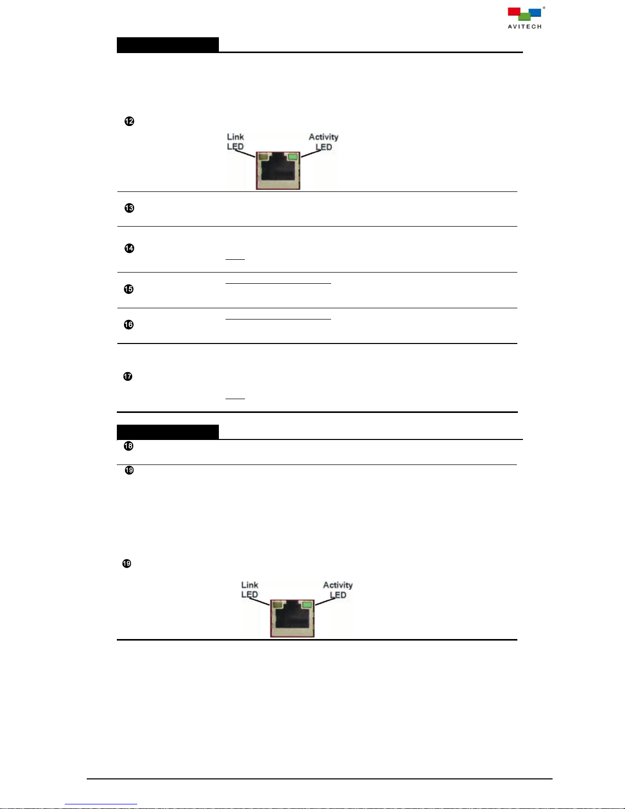
IP
Ethernet connector for HTTP commands or third-party control as well
as for connecting to a gigabit IGMP switch for detecting TX
(transmitters) and RX (receivers) for use together with the SUHD-IP.
K/M
USB keyboard/mouse for KVM and in-system GUI operation.
Dip Switches
Resets the Sequoia UHD to factory-default settings.
REF IN
Future option – For Sequoia UHD+ only
For genlock signal input that supports:
Black Burst, Tri-level and Sequoia UHD+ proprietary.
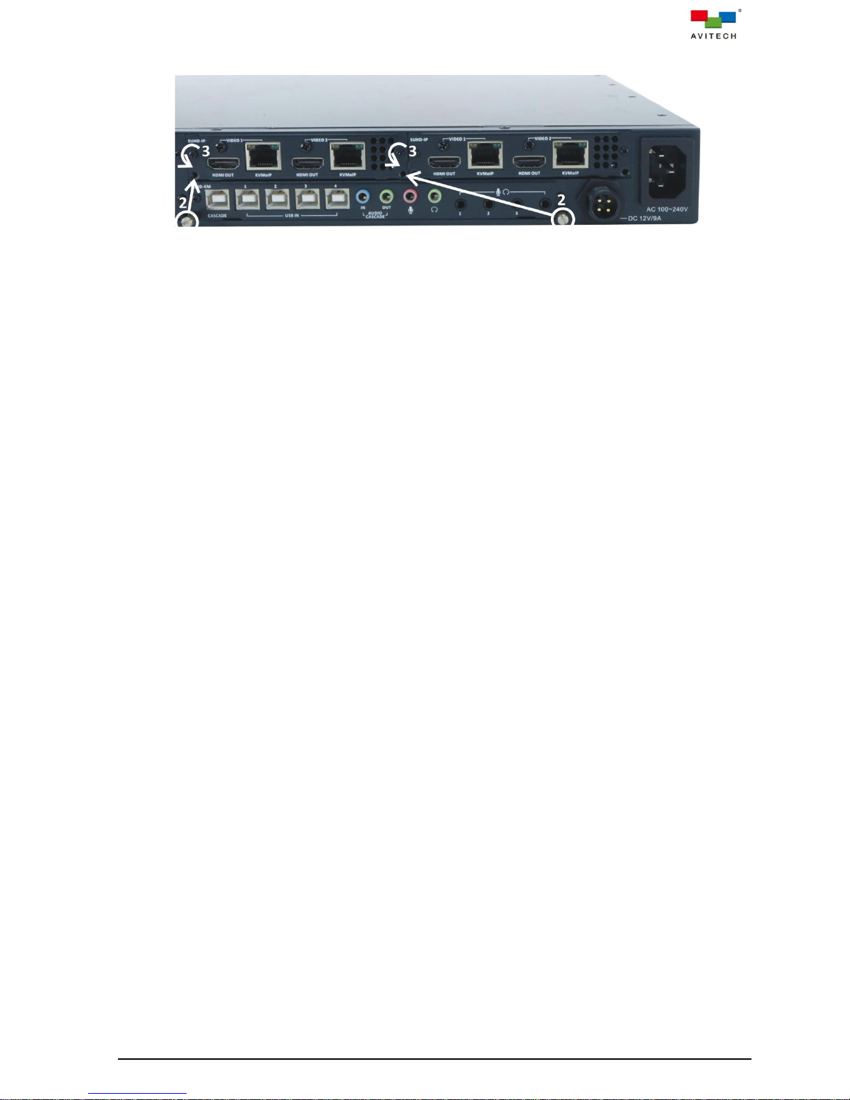
1.4 Connections to the Sequoia UHD / UHD+ / UHD/T / UHD/T+
Figure 1-1 Sequoia UHD / UHD+ Components
6
Page 14

SUHD-MB
REF OUT
Future option – For Sequoia UHD+ only
For genlock signal output that supports Sequoia UHD+ proprietary.
HDMI IN 1 ~ 4
Four HDMI type A connectors for HDMI / DVI-D input sources (DVI to
HDMI adapters may be needed).
Note: Transmission of audio signal is not included when using the DVI
to HDMI adapter.
CASCADE IN
For Sequoia UHD+ only
BNC connector for externally cascaded SDI input signal from an
upstream Sequoia UHD+ / UHD/T+ (CASCADE OUT).
CASCADE OUT
For Sequoia UHD+ only
BNC connector for externally cascaded SDI output signal to a
downstream Sequoia UHD+ / UHD/T+ (CASCADE IN).
HDMI OUT
HDMI type A connector for HDMI/DVI monitor (HDMI to DVI adapters
may be needed).
Note: Transmission of audio signal is not included when using the DVI
to HDMI adapter.
SUHD-IP
HDMI OUT
(VIDEO 1/2)
HDMI type A connector for pass-through output from the RJ-45 input
source
KVMoIP
(VIDEO 1/2)
RJ-45 connectors for connecting Avitech’s Pacific X-IPT via CAT-5e/6
Ethernet cables.
Transmission of HDMI/DVI (with adapter) video, embedded audio
and USB keyboard/mouse control signals
“Link” LED indicator glows yellow when connection with Avitech’s
Pacific X-IPT is established
“Activity” LED indicator blinks green when data (signal) is
transmitted
SUHD-KM
CASCADE
USB type B port for externally cascaded keyboard/mouse control signal.
USB IN 1 ~ 4
Four USB type B ports for connecting the respective computers’ USB
type A ports via standard USB A/B cables; and transmission of
keyboard/mouse control signals to source computers.
AUDIO
CASCADE IN
Audio connector for externally cascaded audio input signal from an
upstream SUHD-KM (AUDIO CASCADE OUT).
AUDIO
CASCADE OUT
Audio connector for externally cascaded audio output signal to a
downstream SUHD-KM (AUDIO CASCADE IN).
Connects to the red connector for microphone function.
Connects to the green connector for headphone function or set of
speakers (stereo).
1 / 2 / 3 / 4
Connects to the respective remote computer’s (1~4) audio connectors
(through the Sequoia male to dual male Y splitter audio cable). Since
these audio ports are bi-directional, depending on your setting in the
right-click menu item “Audio routing” (see chapter 4 for details), connect
a set of headphone or stereo speakers for audio output; or connect a
microphone for audio input.
Rear Panel
Power
(DC 12 V / 9 A)
Connects to the 12 V DC / 9 A power adapter for redundant power.
Power In
AC 100~240 V 50/60Hz
Table 1-4 Sequoia UHD / UHD+ Component Description
7
Page 15

Front Panel
Indicator
Glows green when the Sequoia UHD/T / UHD/T+ is connected to
power.
SUHD-MB/IP
PC
USB port connection to a fifth (local) computer and passes the
keyboard/mouse control from it.
IN
Connects to a fifth (local) computer’s audio connectors via the
proprietary Sequoia male to dual male Y splitter audio cable. Since this
audio port is bi-directional, depending on your setting in the right-click
menu item “Audio routing” (see chapter 4 for details), connect a set of
headphone or stereo speakers for audio output; or connect a
microphone for audio input.
IP
Ethernet connector for HTTP commands or third-party control as well
as for connecting to a gigabit IGMP switch for detecting TX
(transmitters) and RX (receivers) for use together with the SUHD-IP
module.
K/M
USB keyboard/mouse for KVM and in-system GUI operation.
Dip Switches
Resets the Sequoia UHD to factory-default settings.
REF IN
For genlock signal input that supports:
Black Burst, Tri-level and Sequoia UHD/T+ proprietary.
REF OUT
For genlock signal output that supports Sequoia UHD/T+ proprietary.
Connects to the red connector for microphone function.
Connects to the green connector for headphone function or set of
speakers (stereo).
SFP (slot)
Accepts one gigabit SFP (small form-factor pluggable) single-mode
transceiver module.
Figure 1-2 Sequoia UHD/T / UHD/T+ Components
8
Page 16
SUHD-MB/IP
KVMoIP (RJ45)
RJ-45 connector for connecting with Avitech’s Pacific X-IPTR /
X-IPTRS / X-IPr (receiver) via CAT-5e/6 Ethernet cables.
Transmission of HDMI/DVI (with adapter) video, embedded audio,
USB keyboard/mouse control, UART, RS-232 and infrared signals
“Link” LED indicator glows orange when connection with another
Avitech’s Pacific X-IPTR / X-IPTRS / X-IPr (receiver) is established
“Activity” LED indicator blinks green on data (signal) transmission
HDMI IN
Accepts HDMI input source from the HDMI OUT port below it so that
image signal is also included when transmitting through the KVMoIP
port (previous port).
HDMI IN 1 ~ 4
Four HDMI type A connectors for HDMI / DVI-D input sources (DVI to
HDMI adapters may be needed).
Note: Transmission of audio signal is not included when using the DVI
to HDMI adapter.
CASCADE IN
For Sequoia UHD/T+ only
BNC connector for externally cascaded SDI input signal from an
upstream Sequoia UHD+ / UHD/T+ (CASCADE OUT).
CASCADE OUT
For Sequoia UHD/T+ only
BNC connector for externally cascaded SDI output signal to a
downstream Sequoia UHD+ / UHD/T+ (CASCADE IN).
HDMI OUT
HDMI type A connector for routing video signal to the HDMI IN port
above it.
Or, for connecting to a HDMI/DVI monitor (HDMI to DVI adapters may
be needed).
Note: Transmission of audio signal is not included when using the DVI
to HDMI adapter to connect to monitor.
SUHD-IP
HDMI OUT
(VIDEO 1/2)
HDMI type A connector for pass-through output from the SFP / RJ-45
input source
SFP (slot)
(VIDEO 1/2)
Accepts one gigabit SFP (small form-factor pluggable) single-mode
transceiver module.
Or
KVMoIP (RJ-45)
(VIDEO 1/2)
RJ-45 connector for connecting with Avitech’s Pacific X-IPT / X-IPTR /
X-IPTRS / X-IPt (transmitter) via CAT-5e/6 Ethernet cables.
Transmission of HDMI/DVI (with adapter) video, embedded audio
and USB keyboard/mouse control signals
“Link” LED indicator glows yellow when connection with Avitech’s
Pacific X-IPT / X-IPTR / X-IPTRS / X-IPt (transmitter) is established
“Activity” LED indicator blinks green on data (signal) transmission
9
Page 17
SUHD-2HD
IN (UHD)
Accepts HDMI 4K30 video/audio input.
LOOP OUT
(UHD)
Connects to HDMI or DVI (via DVI to HDMI adapter) 4K30 monitor.
Audio out is available when connecting to HDMI monitor.
HD HDMI OUT
1 ~ 4
Four HD (1080p) HDMI type A connector of decoded output to video
wall (2×2) from the IN (UHD) input source (4K30).
REF IN
Future option
For genlock signal input that supports:
Black Burst, Tri-level and Sequoia UHD/T+ proprietary.
REF OUT
Future option
For genlock signal output that supports Sequoia UHD/T+ proprietary.
Rear Panel
Power
(DC 12 V / 9 A)
Connects to the 12 V DC / 9 A power adapter for redundant power.
Power In
AC 100~240 V 50/60Hz
Table 1-5 Sequoia UHD/T / UHD/T+ Component Description
10
Page 18

1. Because the Sequoia UHD is available as a customizable system, the illustrations in this chapter and
those used throughout the manual may differ from the model(s) you purchased.
2. Keep a note of which transmitter/receiver is connected to which port. You can use this information later
when you rename transmitters/receivers in the IP TX List and IP RX List tables.
3. You do not have to use all the slots.
2. System Configuration
This chapter provides information on installing and removing a modular card into and out of the Sequoia
UHD chassis. It also discusses the process of setting up your Sequoia UHD.
2.1 Installing a New Module on a Blank Slot
The Sequoia UHD chassis accepts the following modules:
SUHD-MB Module (may be pre-installed from the dealer)
SUHD-MB/IPT Module (may be pre-installed from the dealer)
SUHD-IPc Module
SUHD-IPf Module
SUHD-2HD Module
Keyboard/Mouse Module:
SUHD-KM Module
Installation and removal of the modules follow the same procedures. In this section, a SUHD-IP module
was used as an example.
To install a SUHD-IP module on a blank slot, perform the following steps:
Step 1. Remove the two screws securing the back plate.
Figure 2-1 Remove the Two Plate Screws
Step 2. Remove the back plate.
Figure 2-2 Remove the Back Plate
11
Page 19

Step 3. Align both sides of the SUHD-IP module to the rails of the slot, and then slide it all the way into
the chassis.
Figure 2-3 Align the New Module to the Rail on Both Sides
Step 4. Tighten the screws on both sides to secure the newly installed module to the chassis.
Figure 2-4 Tighten the Module Screws on Both Sides
2.2 Removing a Previously Installed Module
To remove or replace an installed module, perform the following steps:
Step 1. Use a slot head screwdriver to unscrew both puller screws from the right-most module (installed
from the dealer).
Figure 2-5 Remove Puller Screws from the Module
Step 2. Use the just-removed puller screws and screw them to both sides of the module to be removed.
12
Page 20
Step 3. Remove the two screws securing the module to the chassis.
Figure 2-6 Remove the Two Module Screws
Step 4. Grasp both left and right puller screws and pull the module away from the chassis.
Step 5. Install another module (or a back plate cover) to the chassis and tighten both screws.
13
Page 21
In order to ensure the optimum mouse control speed when using your Sequoia UHD, the following are
strongly recommended:
1. The computer’s output resolution for 1080p should be set at 30Hz as well as for 4K at 30Hz.
2. The default Mouse setup (pointer speed) found in the right-click menu item System is 3. Try changing the
value if so desired. See chapter 4 for details.
3. Lastly, try adjusting the value of your Windows operating system > Control Panel > Mouse > Pointer
Options > Motion (Select a pointer speed).
DO NOT place any object on the front and side panels of the Sequoia UHD. Doing so may impair its internal
components and/or its heat dissipation.
2.3 Getting the Sequoia UHD Ready
To control your Sequoia UHD directly, connect a keyboard and mouse to the USB type A ports on
its rear panel.
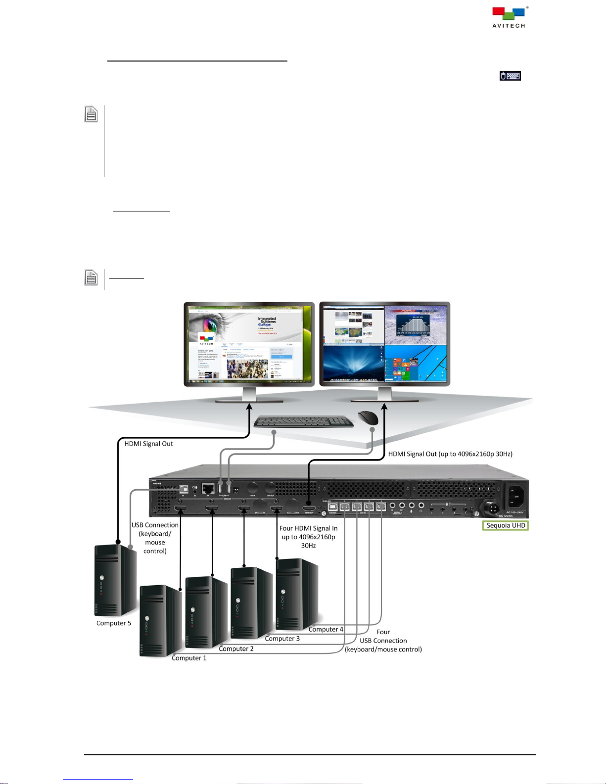
2.3.1 Basic Setup
The following figure show a typical setup with a single Sequoia UHD dual UHD monitor operation for five
systems with one set of keyboard and mouse.
Figure 2-7 Sequoia UHD With Dual UHD Monitor Operation for Five Systems
With One Set of Keyboard and Mouse Setup
Step 1. Connect the first computer’s display output to the HDMI input port (HDMI IN 1) of the Sequoia
UHD. Repeat the step for all source computers (HDMI IN 2 ~ 4).
14
Page 22
Be sure to connect the first computer to HDMI IN 1, the second computer to HDMI IN 2, and so forth.
1. Be sure to connect the first computer to USB IN 1, the second computer to USB IN 2, and so forth.
2. (For Windows 2000 users) Upon connecting your Sequoia UHD to a computer through the USB interface
for the first time, perform the Windows' on-screen steps to initialize the USB connection.
Non-standard keyboards (i.e. keyboards with a USB hub, keyboards that need driver installation and
programmable keyboards, etc.) are not supported.
Step 2. To simultaneously view four concurrent HDMI 1.4 computer sources on a single monitor (up to
4K30), connect a HDMI monitor to the HDMI (HDMI OUT) port of the Sequoia UHD.
Step 3. Connect a USB A/B cable to the first computer’s USB type A port, and connect the other end to
the USB type B port (USB IN 1) of the Sequoia UHD. Repeat this step for all source computers
(USB IN 2 ~ 4).
Step 4. Connect a set of keyboard and mouse to the K/M USB type A ports of the Sequoia UHD that will
be used to operate the Sequoia UHD and the four source computers.
Step 5. Connect a USB A/B cable to the fifth computer’s USB type A port, and connect the other end to
the USB type B port (PC) of the Sequoia UHD. The Sequoia UHD supports a fifth set of KM
(keyboard/mouse) switching on a second monitor next to the multiview display in dual monitor
operation setup.
Step 6. Make sure to power-on the four concurrent computers as well as the fifth computer.
Step 7. Connect one end of the AC power cord to the 100~240 V power in jack on the Sequoia UHD.
Step 8. Connect the other end of the AC power cord to power outlet. After the initial 30 seconds or more
booting time has elapsed, the four windows (each containing image from one of the connected
computers) will appear, along with the Host cursor that can be controlled directly through the
mouse connected to your Sequoia UHD's K/M USB type A ports.
Step 9. (Optional – to achieve power redundancy)
Connect one end of the optional 12 V DC power adapter to the DC 12 V / 9 A power in jack on
the Sequoia UHD.
Step 10. Connect the other end of the optional 12 V DC power adapter to power outlet. Power (AC or
DC) can then be unplugged without affecting the power supply to the Sequoia UHD.
Step 11. The pop-up selections will appear upon moving the Host cursor to
each of the four window’s top-right position:
Click the Enter remote mode icon on a selected window to enter the Sequoia UHD's
Remote mode.
Remote mode allows direct connection to the selected computer through USB interface.
Your Sequoia UHD’s (Host) keyboard and mouse will now control the selected computer; the
Host cursor will disappear when your Sequoia UHD is in Remote mode.
The “Surfer” feature (default setting is ON) is enabled. Moving your cursor out of your current
window's border toward the other window, or pressing Ctrl key and moving mouse to the
window edges that are shared with the other computer’s window will automatically switch
over your Sequoia UHD’s (Host) keyboard and mouse control to that computer.
Press the Pause/Break hot-key on the keyboard or double-click the mouse scroll button
connected to your Sequoia UHD's rear panel to return keyboard and mouse control to the
Sequoia UHD. The Host cursor will reappear.
Move the Host cursor across two displays to access computers confined to each Sequoia
UHD.
15
Page 23
The pop-up selections are not available on the fifth computer’s monitor.
DO NOT place any object on the front and side panels of the Sequoia UHD. Doing so may impair its internal
components and/or its heat dissipation.
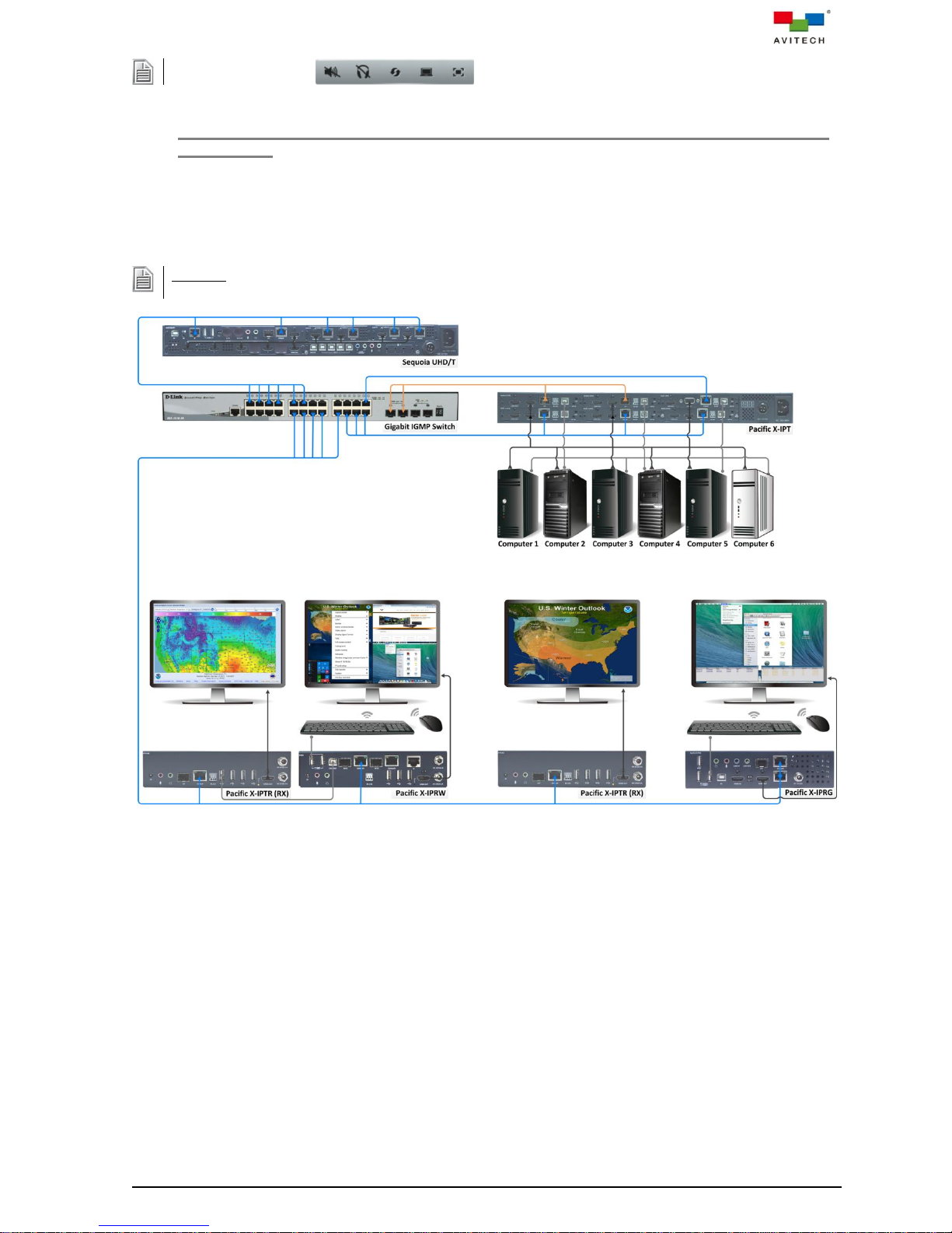
2.3.2 Sequoia UHD/T with Pacific X-IPT / X-IPTR (RX) / X-IPRW / X-IPRG Connected via Gigabit
IGMP Switch
The following figure show a setup of a single Sequoia UHD connected to a Pacific X-IPT source as well
as to a Pacific X-IPTR with Pacific X-IPRW (workstation setup), Pacific X-IPTR (solo) and Pacific
X-IPRG via gigabit IGMP switch.
Figure 2-8 Sequoia UHD/T With Pacific X-IPT / Two X-IPTR (RX) / X-IPRW / X-IPRG
via Gigabit IGMP Switch Setup
16
Page 24
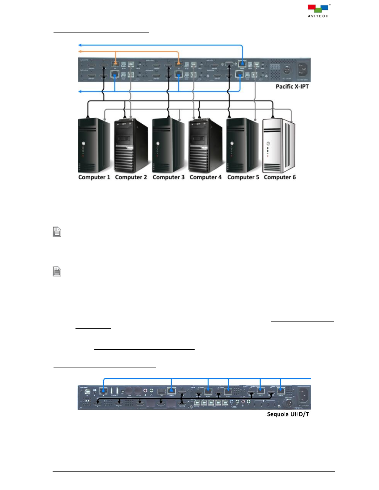
Connections to the Pacific X-IPT
Be sure to connect the first computer to HDMI IN (ID:1), the second computer to HDMI IN (ID:2), and so forth.
1. Be sure to connect the first computer to PC (ID:1), the second computer to PC (ID:2), and so forth.
2. (For Windows 2000 users) Upon connecting your Pacific X-IPT to a computer through the USB interface
for the first time, perform the Windows' on-screen steps to initialize the USB connection.
Figure 2-9 Connections to the Pacific X-IPT Diagram
Step 1. Connect the video sources from remote computer 1~6 to the HDMI IN / VGA IN of Pacific
X-IPTHc (ID:1~3) / X-IPTHf (ID:4~5) / X-IPTVc (ID:6) using the appropriate signal cable.
Step 2. Connect USB A/B cables to the remote computer 1~6’s USB type A port, and connect the other
end to the USB type B port (PC) of Pacific X-IPTHc (ID:1~3) / X-IPTHf (ID:4~5) / X-IPTVc (ID:6).
Step 3. Connect standard CAT-5e/6 Ethernet cables to the KVMoIP (Ethernet) port of Pacific X-IPTHc
(ID:1~3), but leave the other end unconnected for now.
Step 4. Connect gigabit fiber cables to the SFP port of Pacific X-IPTHf (ID:4~5), but leave the other end
unconnected for now.
Step 5. Connect a standard CAT-5e/6 Ethernet cable to the KVMoIP (Ethernet) port of Pacific X-IPTVc
(ID:6), but leave the other end unconnected for now.
Connections to the Sequoia UHD/T
Figure 2-10 Connections to the Sequoia UHD/T Diagram
Step 1. Connect the video source from the left SUHD-IP VIDEO 1 HDMI OUT to the SUHD-MB/IPT
HDMI IN 1 using the appropriate signal cable.
17
Page 25
“On” represents dip switch in the “down” while “Off” represents the dip switch in the “up” position.
Step 2. Connect the video source from the left SUHD-IP VIDEO 2 HDMI OUT to the SUHD-MB/IPT
HDMI IN 2 using the appropriate signal cable.
Step 3. Connect the video source from the right SUHD-IP VIDEO 1 HDMI OUT to the SUHD-MB/IPT
HDMI IN 3 using the appropriate signal cable.
Step 4. Connect the video source from the right SUHD-IP VIDEO 2 HDMI OUT to the SUHD-MB/IPT
HDMI IN 4 using the appropriate signal cable.
Step 5. Connect an HDMI cable from the HDMI IN to the HDMI OUT of SUHD-MB/IPT.
Step 6. Connect a standard CAT-5e/6 Ethernet cable to the SUHD-MB/IPT IP (Ethernet) port, but leave
the other end unconnected for now.
Step 7. Connect a standard CAT-5e/6 Ethernet cable to the SUHD-MB/IPT KVMoIP (Ethernet) port, but
leave the other end unconnected for now.
Step 8. Connect standard CAT-5e/6 Ethernet cables to the four left and right SUHD-IP VIDEO 1/2
KVMoIP (Ethernet) ports, but leave the other ends unconnected for now.
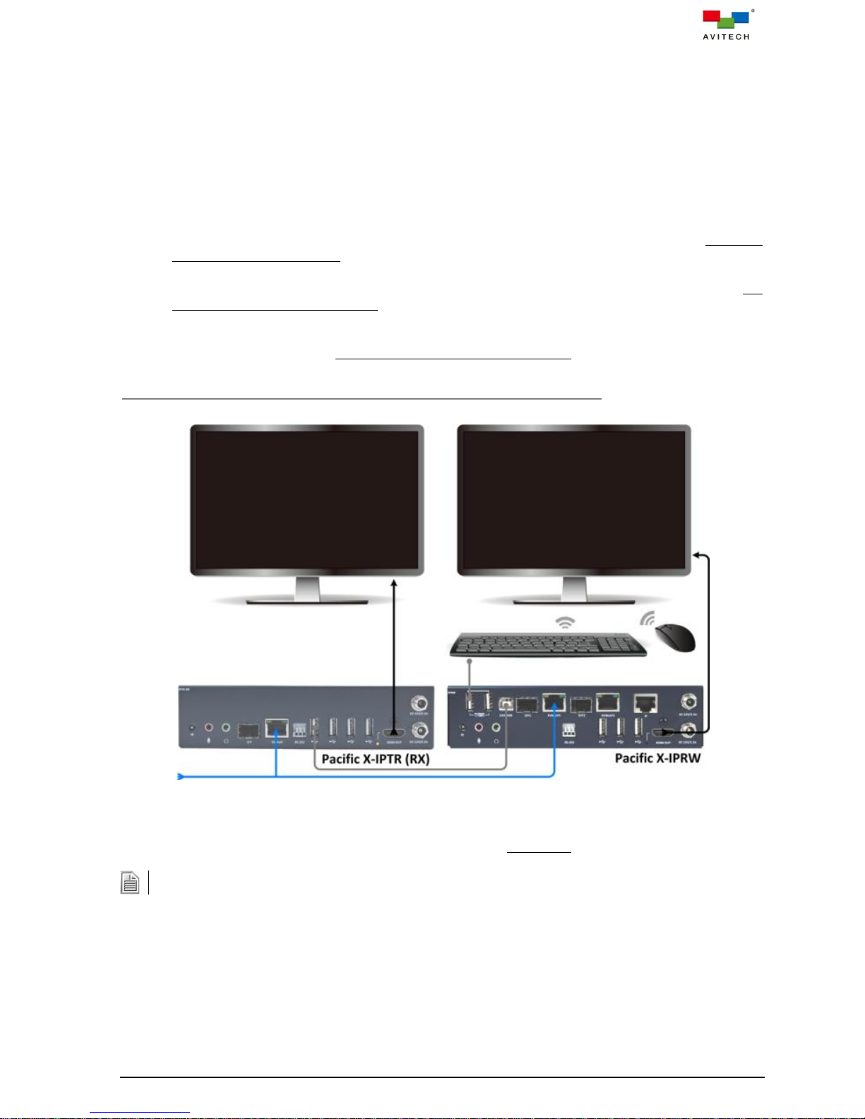
Connections to the Pacific X-IPTR (RX) and Pacific X-IPRW Workstation
Figure 2-11 Connections to the Pacific X-IPTR (RX) and Pacific X-IPRW Workstation Diagram
Step 1. Make certain the Pacific X-IPTR has dip switch set at Off:On:Off (function as receiver).
Step 2. Connect USB A/B cable to the Pacific X-IPTR KVMoIP port, and connect the other end to the
USB type B port (CASCADE) of Pacific X-IPRW.
Step 3. Connect the Pacific X-IPTR’s HDMI OUT to monitor using the appropriate signal cable.
Step 4. Connect the Pacific X-IPRW’s HDMI OUT to monitor using the appropriate signal cable.
18
Page 26

When using your mouse with a 4K display, select a mouse that has a 2000 dpi setting.
Step 5. Connect a set of keyboard and mouse to the USB type A ports of the Pacific X-IPRW that
can be used for Sequoia UHD's right-click menu.
Step 6. Connect a standard CAT-5e/6 Ethernet cable to the KVMoIP (Ethernet) port of Pacific X-IPTR,
but leave the other end unconnected for now.
Step 7. Connect a standard CAT-5e/6 Ethernet cable to the KVMoIP1 (Ethernet) port of Pacific
X-IPRW, but leave the other end unconnected for now.
Connections to the Pacific X-IPTR (RX)
Figure 2-12 Connections to the Pacific X-IPTR (RX) Diagram
Step 1. Make certain the Pacific X-IPTR has dip switch set at Off:On:Off (function as receiver).
Step 2. Connect the HDMI OUT to monitor using the appropriate signal cable.
Step 3. Connect a standard CAT-5e/6 Ethernet cable to the KVMoIP (Ethernet) port, but leave the other
end unconnected for now.
19
Page 27

Connections to the Pacific X-IPRG
When using your mouse with a 4K display, select a mouse that has a 2000 dpi setting.
Figure 2-13 Connections to the Pacific X-IPRG Diagram
Step 1. Connect the HDMI OUT to monitor using the appropriate signal cable.
Step 2. Connect a set of keyboard and mouse to the USB type A ports that will be used to perform
routing via the IP TX List and IP RX List tables.
Step 3. Connect a standard CAT-5e/6 Ethernet cable to the KVMoIP (Ethernet) port, but leave the other
end unconnected for now.
Step 4. Connect a standard CAT-5e/6 Ethernet cable to the IP (Ethernet) port, but leave the other end
unconnected for now.
Powering Up the Devices
Step 1. Connect power to/and boot-up the six remote computers.
Step 2. Connect power to the four monitor displays and turn on the devices.
Step 3. Connect power to the gigabit IGMP switch.
Step 4. Connect power to the Sequoia UHD/T, Pacific X-IPT, two IPTR-RX, X-IPRW and X-IPRG.
Configuring the Pacific X-IPRG
Step 1. Connect the other end of a standard CAT-5e/6 Ethernet cable coming from the IP (Ethernet)
port to the Ethernet port of the gigabit IGMP switch. The distance between the two devices can
be up to 100 meters.
20
Page 28

Notice that the blank IP TX List and IP RX List tables appear onscreen.
An alternative to steps 3 and 4 above is to double-click the name itself and edit it.
Figure 2-14 Blank IP TX List and IP RX List Tables
Step 2. Connect the other end of a standard CAT-5e/6 Ethernet cable coming from the KVMoIP
(Ethernet) port to the Ethernet port of the gigabit IGMP switch. The distance between the two
devices can be up to 100 meters.
Notice that information pertaining to the Pacific X-IPRG appears as the first item in the IP RX
List table.
Step 3. Right-click the entry for Pacific X-IPRG and click to select Rename.
Figure 2-15 Right-click Menu Select Rename
Step 4. Replace the name to help you identify this particular device.
Figure 2-16 Replace the Name
Configuring the Pacific X-IPT
Step 1. Connect the other end of standard CAT-5e/6 Ethernet cable coming from the KVMoIP
(Ethernet) port of Pacific X-IPTHc (ID:1) to the Ethernet port of the gigabit IGMP switch. The
distance between the two devices can be up to 100 meters.
Notice that information pertaining to the Pacific X-IPTHc (ID:1) appears as the first item in the IP
TX List table.
Step 2. Right-click the entry for Pacific X-IPTHc (ID:1) and click to select Rename.
Figure 2-17 Right-click Menu Select Rename
21
Page 29

Step 3. Replace the name to help you identify this particular TX.
An alternative to steps 2 and 3 above is to double-click the name itself and edit it.
An alternative to the previous step is to double-click the channel number itself and edit it.
Figure 2-18 Replace the Name
Step 4. Right-click the entry for Pacific X-IPTHc (ID:1) and click to select Set TX channel. Change the
channel number (0 ~ 9999) as this will serve as a reference when pairing with RX.
Figure 2-19 Change the Channel Number (0 ~ 9999)
Step 5. Perform steps 1~4 for Pacific X-IPTHc (ID:2 and 3).
Step 6. Connect the other end of a gigabit fiber cable coming from the SFP port of Pacific X-IPTHf (ID:4)
to the SFP port of the gigabit IGMP switch. The distance between the two devices depend on
the SFP transceiver module. Repeat steps 2~4 to complete configuration for Pacific X-IPTHf
(ID:4).
Step 7. Connect the other end of a gigabit fiber cable coming from the SFP port of Pacific X-IPTHf (ID:5)
to the SFP port of the gigabit IGMP switch. The distance between the two devices depend on
the SFP transceiver module. Repeat steps 2~4 to complete configuration for Pacific X-IPTHf
(ID:5).
Step 8. Connect the other end of standard CAT-5e/6 Ethernet cable coming from the KVMoIP
(Ethernet) port of Pacific X-IPTVc (ID:6) to the Ethernet port of gigabit IGMP switch. Distance
between the two devices can be up to 100 meters. Repeat steps 2~4 to configure Pacific
X-IPTVc (ID:6).
Configuring the Pacific X-IPTR Workstation
Step 1. Connect the other end of a standard CAT-5e/6 Ethernet cable coming from the KVMoIP
(Ethernet) port to the Ethernet port of the gigabit IGMP switch. The distance between the two
devices can be up to 100 meters.
Step 2. Right-click the entry for this newly added Pacific X-IPTR workstation in the IP RX List table and
click to select Rename. Or, double-click the name itself and edit it.
Step 3. Replace the name to help you identify this particular RX.
22
Page 30

Configuring the Pacific X-IPTR
It is not necessary to rename this particular RX because the system will automatically assign the name Local
CH-1 to it.
The names Local CH-2, Local CH-3 and Local CH-4 will be automatically assigned to these.
Step 1. Connect the other end of a standard CAT-5e/6 Ethernet cable coming from the KVMoIP
(Ethernet) port to the Ethernet port of the gigabit IGMP switch. The distance between the two
devices can be up to 100 meters.
Step 2. Right-click the entry for this newly added Pacific X-IPTR in the IP RX List table and click to
select Rename. Or, double-click the name itself and edit it.
Step 3. Replace the name to help you identify this particular RX.
Configuring the Pacific X-IPRW
Step 1. Connect the other end of a standard CAT-5e/6 Ethernet cable coming from the KVMoIP1
(Ethernet) port to the Ethernet port of the gigabit IGMP switch. The distance between the two
devices can be up to 100 meters.
Step 2. Right-click the entry for this newly added Pacific X-IPRW in the IP RX List table and click to
select Rename. Or, double-click the name itself and edit it.
Step 3. Replace the name to help you identify this particular RX.
Configuring the Sequoia UHD/T
Step 1. Connect the other end of a standard CAT-5e/6 Ethernet cable coming from the SUHD-MB/IPT
IP (Ethernet) port to the Ethernet port of the gigabit IGMP switch. The distance between the two
devices can be up to 100 meters.
This allows you to access the Sequoia UHD right-click menu items from the Pacific X-IPRW.
Step 2. Connect the other end of a standard CAT-5e/6 Ethernet cable coming from the SUHD-MB/IPT
KVMoIP (Ethernet) port to the Ethernet port of the gigabit IGMP switch. The distance between
the two devices can be up to 100 meters.
Step 3. Right-click the entry for Sequoia UHD/T in the IP TX List table and click to select Rename. Or,
double-click the name itself and edit it.
Step 4. Replace the name to help you identify this particular TX.
Step 5. Change the channel number (0 ~ 9999) as this will serve as a reference when pairing with a RX.
Step 6. Connect the other end of a standard CAT-5e/6 Ethernet cable coming from the left SUHD-IP
VIDEO 1 KVMoIP (Ethernet) port to the Ethernet port of the gigabit IGMP switch. The distance
between the two devices can be up to 100 meters.
Step 7. Perform step 6 for RXs associated with the left SUHD-IP VIDEO 2 KVMoIP (Ethernet) port as
well as for the right SUHD-IP VIDEO 1/2 KVMoIP (Ethernet) ports.
23
Page 31

Upon changing the existing routes, the EDID of each display device will be re-assessed and information
updated to the respective source (connected to TX).
Turning the RX EDID Read "Off" will help prevent display blinking during video routing.
When a remote source (i.e. TX1) that was routed (paired) to an RX window in Sequoia UHD (i.e. Image 1) is
routed to a second RX (i.e. Pacific X-IPTR), and that Pacific X-IPTR acquires keyboard and mouse control
(by pressing the LINK ON/OFF button for five seconds), will cause the Sequoia UHD's "Surfer" feature when
mouse travel enters Image 1's window to be disabled.
Routing TX to RX
To assign TX and RX routing (or pairing), the following methods can be used:
Method 1. On the IP TX / RX List tables, use the mouse to drag a TX on top of an RX. Channel ID value
for RX will then follow the Channel ID value of TX. Or,
Method 2. Click to highlight (select) a TX, then press Ctrl + C hotkey, and then click to highlight (select)
a RX, then press Ctrl + V hotkey. To assign a TX to multiple RXs, press Ctrl prior to clicking
each RX and then press Ctrl + V hotkey. Channel ID value for multiple RXs will then follow
the Channel ID value of TX. Or,
Method 3. Right-click a TX and click Set TX channel in the menu. Copy the RX Channel ID value that
you wish to assign pairing. (You can also double-click the channel number and edit it
directly.) Or,
Method 4. On the IP TX List table, use the mouse to drag a TX on to a window.
EDID Read
Right-click a RX in the IP RX List table and click EDID Read to toggle automatic detection of EDID from
the display device(s). Default is "On".
Figure 2-20 “EDID Read” Setting
Scenario 1. Upon switching a signal to a display device connected to RX, the preferred EDID of that
display device will be detected and information updated to the respective source
(connected to TX). Source device will then configure its output based on obtained EDID.
Scenario 2. When routing a signal to multiple display devices routed from the same TX, Sequoia UHD
will assess the preferred EDID of each display device and update the information to the
respective source (connected to TX). Source device will then configure its output based on
the assessed EDID and output at the optimum format supported by all the displays.
Off
The EDID of the connected display device (connected to RX) will no longer be detected. The source
device (connected to TX) will configure its output based on the latest obtained EDID during which RX
EDID Read was on.
Sequoia UHD “Surfer” Mode Limitation
24
Page 32
In summary: Sequoia UHD only allows a dedicated TX pairing (routing) to each of its four RXs. When any of
the TX should also be paired (routed) to another RX other than Sequoia UHD, and that RX should acquire
keyboard and mouse control, when mouse travel in Sequoia UHD's Remote operation mode (in "Surfer"
mode) enters the window with shared TX pairing, "Surfer" mode will be automatically disabled.
To re-enable "Surfer" mode in Sequoia UHD's Remote operation mode, perform the following steps:
Step 1. Double-click the mouse scroll button or press Pause/Break hot-key to exit Remote operation
mode and return to Host operation mode in Sequoia UHD.
Step 2. Route (pair) any other remote source (i.e. TX6) to the Image 1 window so that only one pairing of
TX to Pacific X-IPTR window remains.
Step 3. Double-click any of the quad windows in Sequoia UHD to enter Remote operation mode.
Notice that the "Surfer" feature is now functioning in all four "Image" windows.
25
Page 33
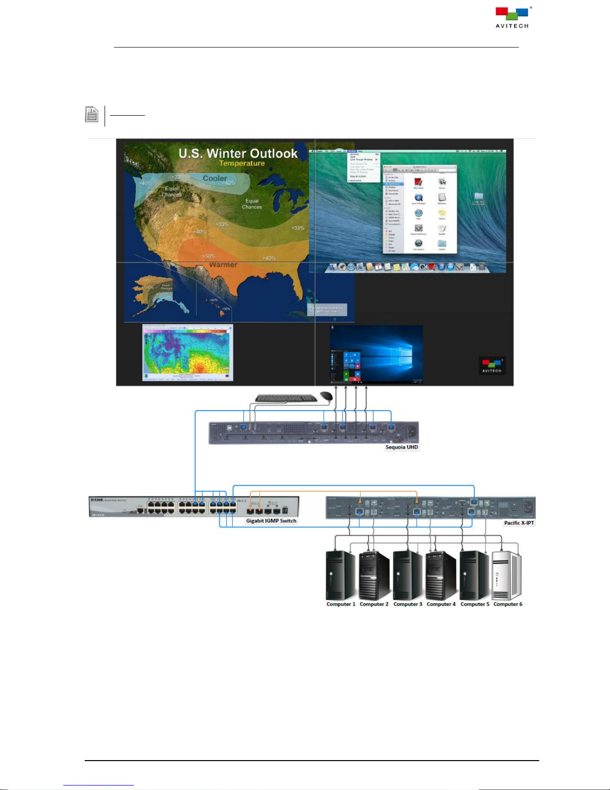
DO NOT place any object on the front and side panels of the Sequoia UHD. Doing so may impair its internal
components and/or its heat dissipation.
2.3.3 Sequoia UHD to 2×2 Video Wall with Pacific X-IPT Connected via Gigabit IGMP Switch
The following figure show a setup of a single Sequoia UHD 2×2 video wall connected to a Pacific X-IPT
source via gigabit IGMP switch.
Figure 2-21 Sequoia UHD Video Wall with Pacific X-IPT via Gigabit IGMP Switch Setup
26
Page 34
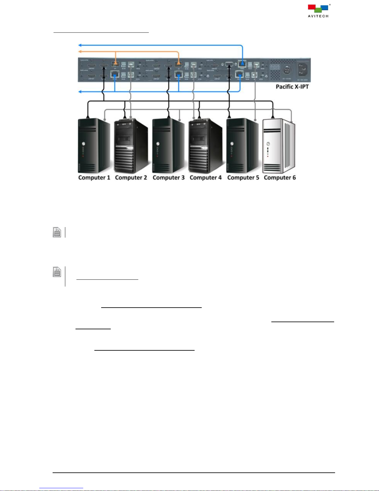
Connections to the Pacific X-IPT
Be sure to connect the first computer to HDMI IN (ID:1), the second computer to HDMI IN (ID:2), and so forth.
1. Be sure to connect the first computer to PC (ID:1), the second computer to PC (ID:2), and so forth.
2. (For Windows 2000 users) Upon connecting your Pacific X-IPT to a computer through the USB interface
for the first time, perform the Windows' on-screen steps to initialize the USB connection.
Figure 2-22 Connections to the Pacific X-IPT Diagram
Step 1. Connect the video sources from remote computer 1~6 to the HDMI IN / VGA IN of Pacific
X-IPTHc (ID:1~3) / X-IPTHf (ID:4~5) / X-IPTVc (ID:6) using the appropriate signal cable.
Step 2. Connect USB A/B cables to the remote computer 1~6’s USB type A port, and connect the other
end to the USB type B port (PC) of Pacific X-IPTHc (ID:1~3) / X-IPTHf (ID:4~5) / X-IPTVc (ID:6).
Step 3. Connect standard CAT-5e/6 Ethernet cables to the KVMoIP (Ethernet) port of Pacific X-IPTHc
(ID:1~3), but leave the other end unconnected for now.
Step 4. Connect gigabit fiber cables to the SFP port of Pacific X-IPTHf (ID:4~5), but leave the other end
unconnected for now.
Step 5. Connect a standard CAT-5e/6 Ethernet cable to the KVMoIP (Ethernet) port of Pacific X-IPTVc
(ID:6), but leave the other end unconnected for now.
27
Page 35
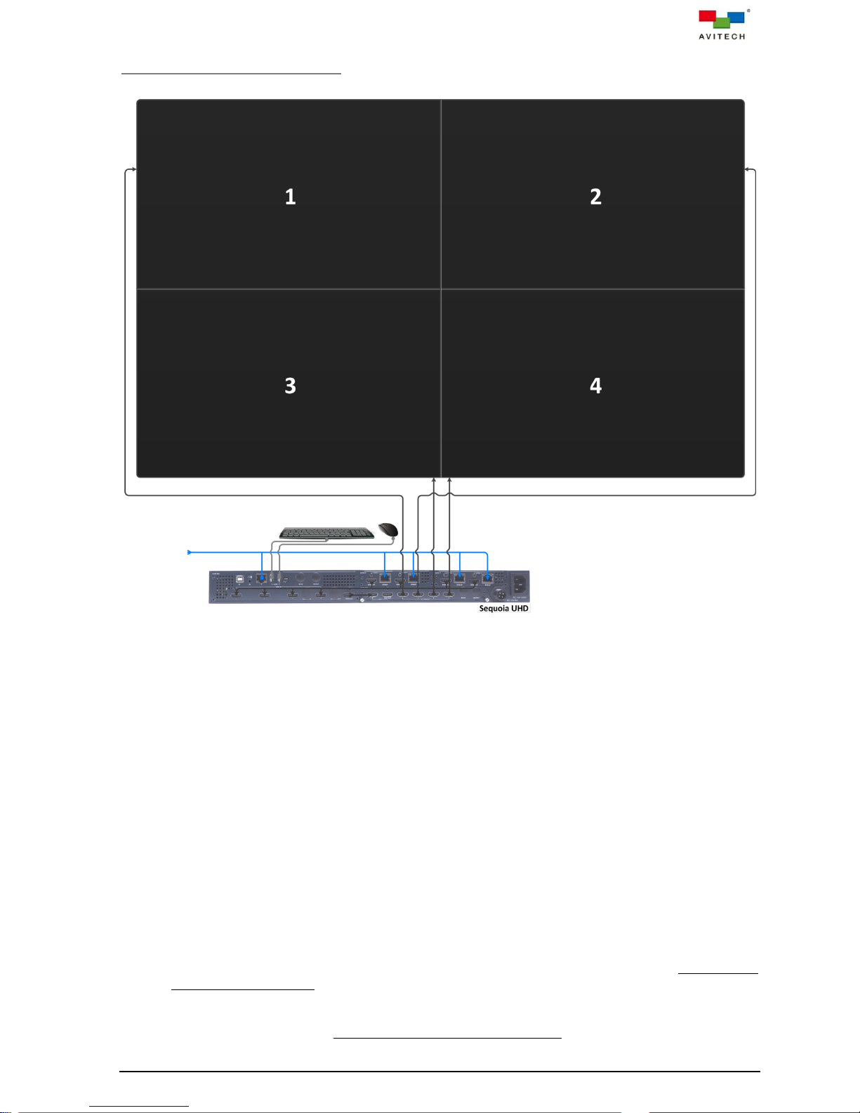
Connections to the Sequoia UHD
Figure 2-23 Connections to the Sequoia UHD Diagram
Step 1. Connect the video source from the left SUHD-IP VIDEO 1 HDMI OUT to the SUHD-MB HDMI IN
1 using the appropriate signal cable.
Step 2. Connect the video source from the left SUHD-IP VIDEO 2 HDMI OUT to the SUHD-MB HDMI IN
2 using the appropriate signal cable.
Step 3. Connect the video source from the right SUHD-IP VIDEO 1 HDMI OUT to the SUHD-MB HDMI
IN 3 using the appropriate signal cable.
Step 4. Connect the video source from the right SUHD-IP VIDEO 2 HDMI OUT to the SUHD-MB HDMI
IN 4 using the appropriate signal cable.
Step 5. Connect an HDMI cable from the HDMI OUT of SUHD-MB to the IN UHD of SUHD-2HD.
Step 6. Connect the video source from the SUHD-2HD HD HDMI OUT 1~4 to the corresponding
sequence of video wall screens using the appropriate signal cables. For future reference, we will
refer to the video wall’s screens as “wall screens.”
Step 7. Connect a standard CAT-5e/6 Ethernet cable to the SUHD-MB IP (Ethernet) port, but leave the
other end unconnected for now.
Step 8. Connect standard CAT-5e/6 Ethernet cables to the four left and right SUHD-IP VIDEO 1/2
KVMoIP (Ethernet) ports, but leave the other end unconnected for now.
28
Page 36
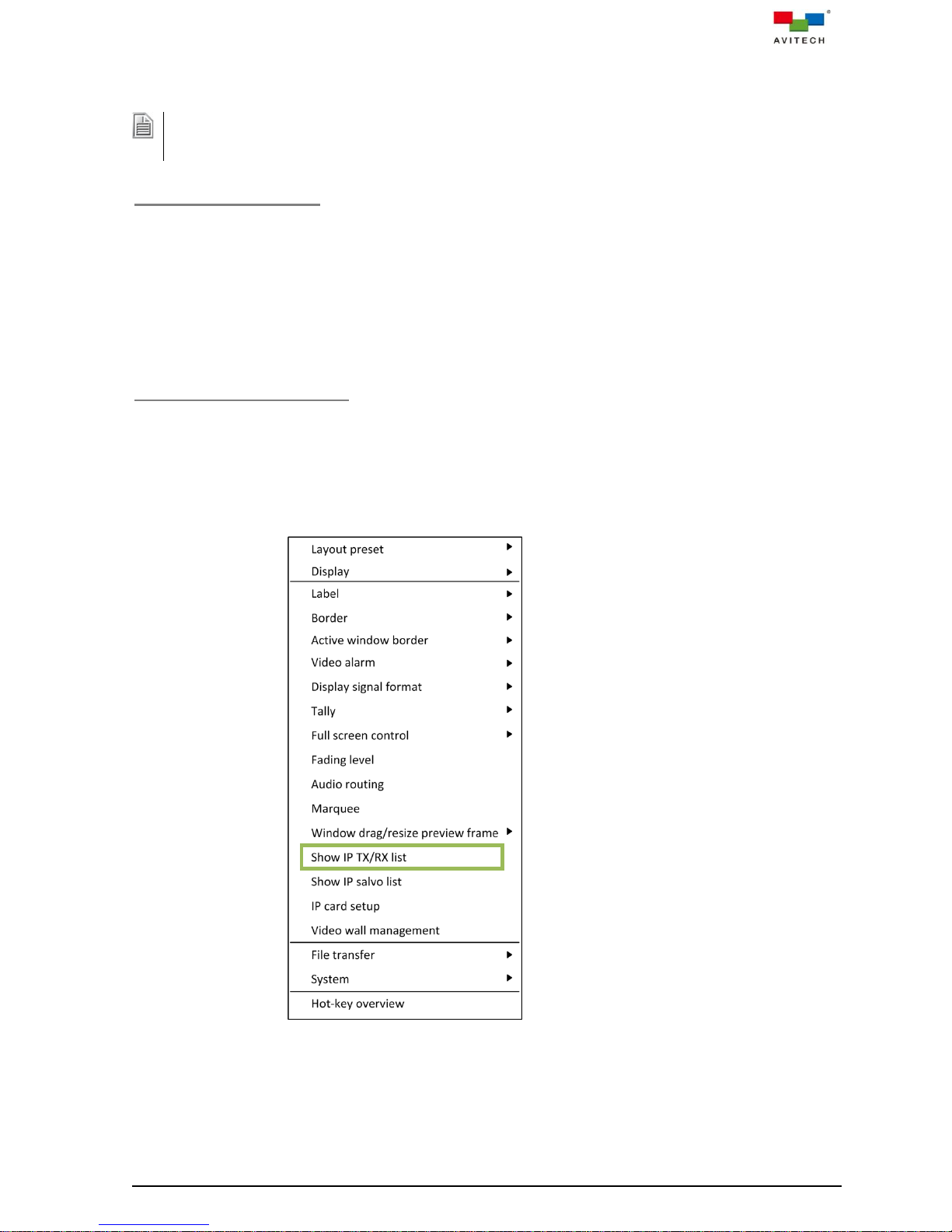
1. When using your mouse with a 4K display, select a mouse that has a 2000 dpi setting.
2. Non-standard keyboards (i.e. keyboards with a USB hub, keyboards that need driver installation and
programmable keyboards, etc.) are not supported.
Step 9. Connect a set of keyboard and mouse to the K/M USB type A ports that will be used to perform
routing via the IP TX List and IP RX List tables as well as access the right-click menu.
Powering Up the Devices
Step 1. Connect power to/and boot-up the six remote computers.
Step 2. Connect power to the video wall screens and turn on the devices.
Step 3. Connect power to the gigabit IGMP switch.
Step 4. Connect power to the Sequoia UHD and Pacific X-IPT.
Configuring the Pacific X-IPT
Step 1. Connect the other end of standard CAT-5e/6 Ethernet cable coming from the KVMoIP
(Ethernet) port of Pacific X-IPTHc (ID:1) to the Ethernet port of the gigabit IGMP switch. The
distance between the two devices can be up to 100 meters.
Step 2. Press
Or right-click your mouse anywhere on the wall screens and on the menu appearing, click
IP TX/RX list
Ctrl, Ctrl, M
hotkey.
Show
to call up the IP TX
and IP RX
List
List
tables.
Notice that information pertaining to the Pacific X-IPTHc (ID:1) appears as the first item in the IP
TX List table.
29
Page 37
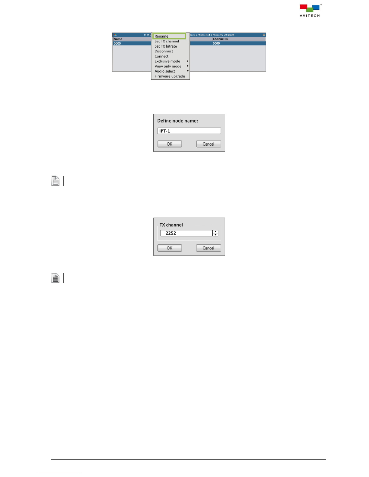
Step 3. Right-click the entry for Pacific X-IPTHc (ID:1) and click to select Rename.
An alternative to steps 3 and 4 above would be to double-click the name and edit it directly.
An alternative to the previous step would be to double-click the channel number and edit it directly.
Figure 2-24 Right-click Menu Select Rename
Step 4. Replace the name to help you identify this particular TX.
Figure 2-25 Replace the Name
Step 5. Right-click the entry for Pacific X-IPTHc (ID:1) and click to select Set TX channel. Change the
channel number (0 ~ 9999) as this will serve as reference when pairing with RX.
Figure 2-26 Change the Channel Number (0 ~ 9999)
Step 6. Perform steps 1~5 for Pacific X-IPTHc (ID:2 and 3).
Step 7. Connect the other end of a gigabit fiber cable coming from the SFP port of Pacific X-IPTHf (ID:4)
to the SFP port of the gigabit IGMP switch. The distance between the two devices depend on
the SFP transceiver module. Repeat steps 2~5 to complete configuration for Pacific X-IPTHf
(ID:4).
Step 8. Connect the other end of a gigabit fiber cable coming from the SFP port of Pacific X-IPTHf (ID:5)
to the SFP port of the gigabit IGMP switch. The distance between the two devices depend on
the SFP transceiver module. Repeat steps 2~5 to complete configuration for Pacific X-IPTHf
(ID:5).
Step 9. Connect the other end of standard CAT-5e/6 Ethernet cable coming from the KVMoIP
(Ethernet) port of Pacific X-IPTVc (ID:6) to the Ethernet port of gigabit IGMP switch. Distance
between the two devices can be up to 100 meters. Repeat steps 2~5 to configure Pacific
X-IPTVc (ID:6).
30
Page 38
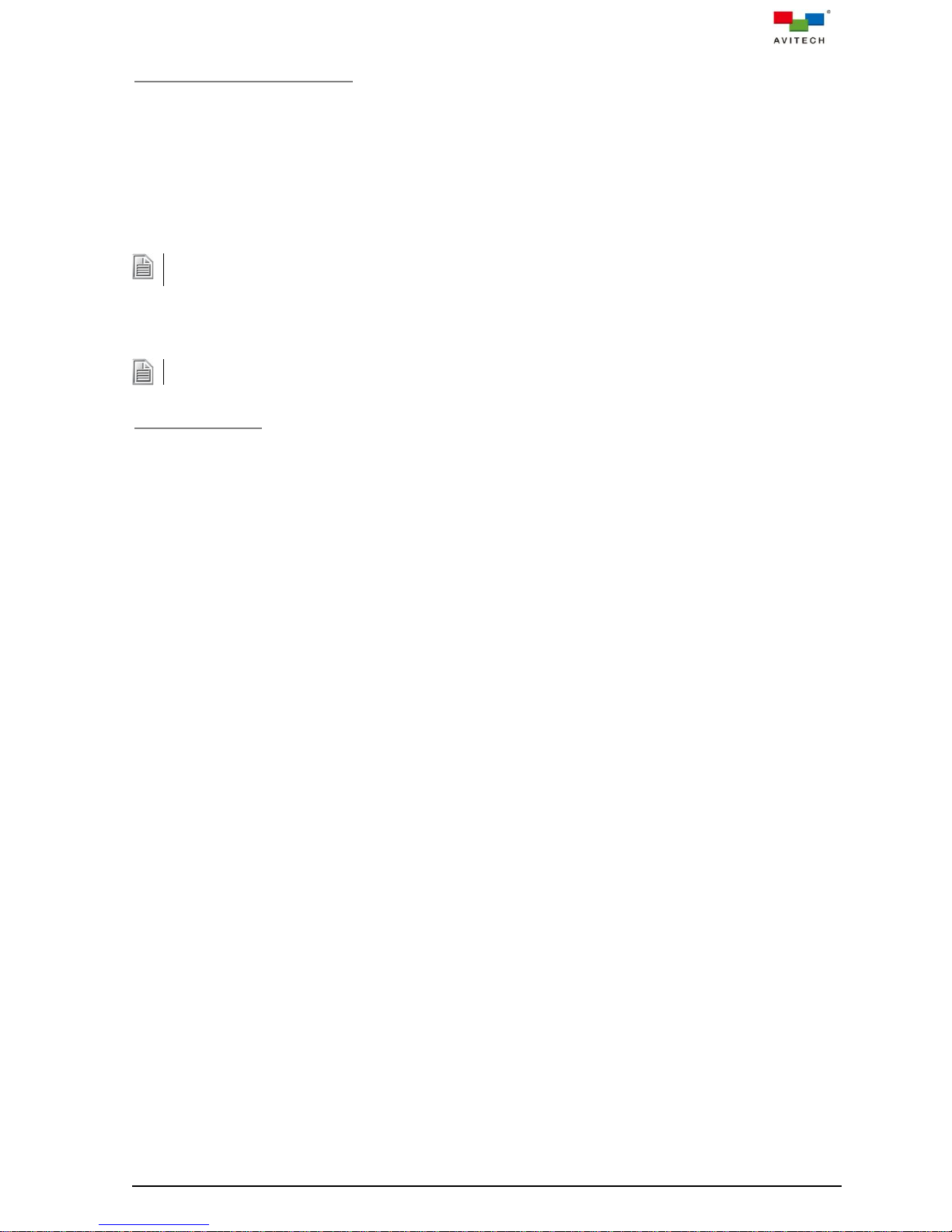
It is not necessary to rename this particular RX because the system will automatically assign the name Local
CH-1 to it.
The names Local CH-2, Local CH-3 and Local CH-4 will be automatically assigned to these.
Configuring the Sequoia UHD
Step 1. Connect the other end of a standard CAT-5e/6 Ethernet cable coming from the SUHD-MB IP
(Ethernet) port to the Ethernet port of the gigabit IGMP switch. The distance between the two
devices can be up to 100 meters.
Step 2. Connect the other end of a standard CAT-5e/6 Ethernet cable coming from the left SUHD-IP
VIDEO 1 KVMoIP (Ethernet) port to the Ethernet port of the gigabit IGMP switch. The distance
between the two devices can be up to 100 meters.
Step 3. Perform step 2 for RXs associated with the left SUHD-IP VIDEO 2 KVMoIP (Ethernet) port as
well as for the right SUHD-IP VIDEO 1/2 KVMoIP (Ethernet) ports.
Routing TX to RX
To assign TX and RX routing (or pairing), the following methods can be used:
Method 1. On the IP TX / RX List tables, use the mouse to drag a TX on top of an RX. Channel ID value
for RX will then follow the Channel ID value of TX. Or,
Method 2. Click to highlight (select) a TX, then press Ctrl + C hotkey, and then click to highlight (select)
a RX, then press Ctrl + V hotkey. To assign a TX to multiple RXs, press Ctrl prior to clicking
each RX and then press Ctrl + V hotkey. Channel ID value for multiple RXs will then follow
the Channel ID value of TX. Or,
Method 3. Right-click a TX and click Set TX channel in the menu. Copy the RX Channel ID value that
you wish to assign pairing. (You can also double-click the channel number and edit it
directly.) Or,
Method 4. On the IP TX List table, use the mouse to drag a TX on to a window.
31
Page 39

DO NOT place any object on the front and side panels of the Sequoia UHD. Doing so may impair its internal
components and/or its heat dissipation.
2.3.4 Two Sequoia UHD/T+ to 2×3 Video Wall with Two Pacific X-IPT Connected via Gigabit IGMP
Switch
The following figure show a setup of a two Sequoia UHDs 2×3 video wall connected to two Pacific X-IPT
sources via gigabit IGMP switch.
Figure 2-27 Two Sequoia UHDs Video Wall with Two Pacific X-IPT via Gigabit IGMP Switch Setup
32
Page 40
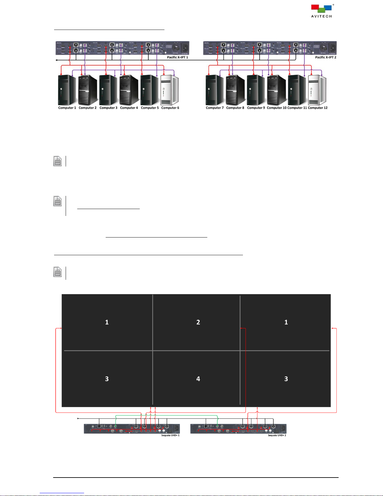
Be sure to connect the first computer to HDMI IN (ID:1), the second computer to HDMI IN (ID:2), and so forth.
1. Be sure to connect the first computer to PC (ID:1), the second computer to PC (ID:2), and so forth.
2. (For Windows 2000 users) Upon connecting your Pacific X-IPT to a computer through the USB interface
for the first time, perform the Windows' on-screen steps to initialize the USB connection.
Before proceeding with multiple Sequoia UHD+ configuration, be sure that each Sequoia UHD+ is set to a
unique IP address (default is 192.168.0.5). Use the right-click menu System > Network.
Connections to the Two Pacific X-IPT
Figure 2-28 Connections to the Two Pacific X-IPT Diagram
Step 1. Connect the video sources from remote computer 1~12 to the HDMI IN of Pacific X-IPTHc
(ID:1~12) using the appropriate signal cable.
Step 2. Connect USB A/B cables to the remote computer 1~12’s USB type A port, and connect the other
end to the USB type B port (PC) of Pacific X-IPTHc (ID:1~12).
Step 3. Connect standard CAT-5e/6 Ethernet cables to the KVMoIP (Ethernet) port of Pacific X-IPTHc
(ID:1~12), but leave the other end unconnected for now.
Connections of the Two Sequoia UHD+ Connect to Wall Display
Figure 2-29 Connections to the Two Sequoia UHD+ With Wall Display Diagram
33
Page 41

1. When using your mouse with a 4K display, select a mouse that has a 2000 dpi setting.
2. Non-standard keyboards (i.e. keyboards with a USB hub, keyboards that need driver installation and
programmable keyboards, etc.) are not supported.
On the Sequoia UHD+ 1
Step 1. Connect the video source from the left SUHD-IP VIDEO 1 HDMI OUT to the SUHD-MB HDMI IN
1 using the appropriate signal cable.
Step 2. Connect the video source from the left SUHD-IP VIDEO 2 HDMI OUT to the SUHD-MB HDMI IN
2 using the appropriate signal cable.
Step 3. Connect the video source from the right SUHD-IP VIDEO 1 HDMI OUT to the SUHD-MB HDMI
IN 3 using the appropriate signal cable.
Step 4. Connect the video source from the right SUHD-IP VIDEO 2 HDMI OUT to the SUHD-MB HDMI
IN 4 using the appropriate signal cable.
Step 5. Connect an HDMI cable from the HDMI OUT of SUHD-MB to the IN UHD of SUHD-2HD.
Step 6. Connect the video source from the SUHD-2HD HD HDMI OUT 1~4 to the corresponding
sequence of video wall screens using the appropriate signal cables. For future reference, we will
refer to the video wall’s screens as “wall screens.” (See the above figure as guide.)
Step 7. Connect a standard CAT-5e/6 Ethernet cable to the SUHD-MB IP (Ethernet) port, but leave the
other end unconnected for now.
Step 8. Connect standard CAT-5e/6 Ethernet cables to the four left and right SUHD-IP VIDEO 1/2
KVMoIP (Ethernet) ports, but leave the other end unconnected for now.
On the Sequoia UHD+ 2
Step 1. Perform steps 1~5 just like for the above Sequoia UHD+ 1.
Step 2. Connect the video source from the SUHD-2HD HD HDMI OUT 1 and 3 to the corresponding
sequence of video wall screens using the appropriate signal cables. (See the above figure as
guide.)
Step 3. Perform steps 7~8 just like for the above Sequoia UHD+ 1.
Step 4. Connect a BNC cable from the REF OUT of Sequoia UHD+ 1 SUHD-MB to the REF IN of
Sequoia UHD+ 2 SUHD-MB.
Connections to the Controlling Sequoia UHD/T+
Figure 2-30 Connections to the Sequoia UHD/T+ Diagram
34
Page 42

Step 1. Connect the video source from the left SUHD-IP VIDEO 1 HDMI OUT to the SUHD-MB/IPT
HDMI IN 1 using the appropriate signal cable.
Step 2. Connect the video source from the left SUHD-IP VIDEO 2 HDMI OUT to the SUHD-MB/IPT
HDMI IN 2 using the appropriate signal cable.
Step 3. Connect the video source from the right SUHD-IP VIDEO 1 HDMI OUT to the SUHD-MB/IPT
HDMI IN 3 using the appropriate signal cable.
Step 4. Connect the video source from the right SUHD-IP VIDEO 2 HDMI OUT to the SUHD-MB/IPT
HDMI IN 4 using the appropriate signal cable.
Step 5. Connect an HDMI cable from the HDMI OUT to the HDMI IN of SUHD-MB.
Step 6. Connect a standard CAT-5e/6 Ethernet cable to the SUHD-MB/IPT IP (Ethernet) port, but leave
the other end unconnected for now.
Step 7. Connect a standard CAT-5e/6 Ethernet cable to the SUHD-MB/IPT KVMoIP (Ethernet) port, but
leave the other end unconnected for now.
Step 8. Connect standard CAT-5e/6 Ethernet cables to the four left and right SUHD-IP VIDEO 1/2
KVMoIP (Ethernet) ports, but leave the other end unconnected for now.
Step 9. Connect a set of keyboard and mouse to the K/M USB type A ports that will be used to perform
routing via the IP TX List and IP RX List tables, access the right-click menu, as well as setup
the video wall’s bezel gap.
Powering Up the Devices
Step 1. Connect power to/and boot-up the twelve remote computers.
Step 2. Connect power to the video wall screens and turn on the devices.
Step 3. Connect power to the gigabit IGMP switch.
Step 4. Connect power to the three Sequoia UHD and two Pacific X-IPT.
Configuring the Two Pacific X-IPT
Step 1. Connect the other end of standard CAT-5e/6 Ethernet cable coming from the KVMoIP
(Ethernet) port of Pacific X-IPTHc (ID:1) to the Ethernet port of the gigabit IGMP switch. The
distance between the two devices can be up to 100 meters.
35
Page 43

An alternative to performing steps 3 and 4 above would be double-click the name and edit it directly.
Step 2. Press
Or right-click your mouse anywhere on the wall screens and on the menu appearing, click
IP TX/RX list
Ctrl, Ctrl, M
hotkey.
Show
to call up the IP TX
and IP RX
List
List
tables.
Notice that information pertaining to the Pacific X-IPTHc (ID:1) appears as the first item in the IP
TX List table.
Step 3. Right-click the entry for Pacific X-IPTHc (ID:1) and click to select Rename.
Figure 2-31 Right-click Menu Select Rename
Step 4. Replace the name to help you identify this particular TX.
Figure 2-32 Replace the Name
36
Page 44

Step 5. Right-click the entry for Pacific X-IPTHc (ID:1) and click to select Set TX channel. Change the
An alternative to performing the previous step would be to double-click the channel number and edit it
directly.
System will automatically assign the name Local CH-1 to it so it is up to the end user whether to assign a new
name.
The names Local CH-2, Local CH-3 and Local CH-4 will be automatically assigned to these so it is up to the
end user whether to assign a new name.
channel number (0 ~ 9999) as this will serve as reference when pairing with RX.
Figure 2-33 Change the Channel Number (0 ~ 9999)
Step 6. Perform steps 1~5 for Pacific X-IPTHc (ID:2~12).
Configuring the Controlling Sequoia UHD/T+ as well as Sequoia UHD+ 1 and 2
Step 1. Connect the other end of a standard CAT-5e/6 Ethernet cable coming from the controlling
Sequoia UHD/T+’s SUHD-MB IP (Ethernet) port to the Ethernet port of the gigabit IGMP switch.
The distance between the two devices can be up to 100 meters.
Step 2. Connect the other end of a standard CAT-5e/6 Ethernet cable coming from the controlling
Sequoia UHD/T+’s left SUHD-IP VIDEO 1 KVMoIP (Ethernet) port to the Ethernet port of the
gigabit IGMP switch. The distance between the two devices can be up to 100 meters.
Step 3. Perform step 2 for RXs associated with the controlling Sequoia UHD/T+’s left SUHD-IP VIDEO 2
KVMoIP (Ethernet) port as well as for the right SUHD-IP VIDEO 1/2 KVMoIP (Ethernet) ports.
Step 4. Perform steps 1~3 again for Sequoia UHD+ 1. The names Local CH-1, Local CH-2, Local
CH-3 and Local CH-4 will again be automatically assigned to its RX so it is highly recommended
to change it to a unique name.
Step 5. Perform steps 1~3 again for Sequoia UHD+ 2. The names Local CH-1, Local CH-2, Local
CH-3 and Local CH-4 will again be automatically assigned to its RX so it is highly recommended
to change it to a unique name.
Routing TX to RX
To assign TX and RX routing (or pairing), the following methods can be used:
Method 1. On the IP TX / RX List tables, use the mouse to drag a TX on top of an RX. Channel ID value
for RX will then follow the Channel ID value of TX. Or,
Method 2. Click to highlight (select) a TX, then press Ctrl + C hotkey, and then click to highlight (select)
a RX, then press Ctrl + V hotkey. To assign a TX to multiple RXs, press Ctrl prior to clicking
each RX and then press Ctrl + V hotkey. Channel ID value for multiple RXs will then follow
the Channel ID value of TX. Or,
Method 3. Right-click a TX and click Set TX channel in the menu. Copy the RX Channel ID value that
you wish to assign pairing. (You can also double-click the channel number and edit it.) Or,
Method 4. On the IP TX List table, use the mouse to drag a TX on to a window.
37
Page 45

Upon re-connecting a keyboard or mouse, the Host cursor may disappear. Move the mouse to allow it to
re-appear.
3. Basic Operations
The Sequoia UHD always operates in one of its two operating modes: Host and Remote mode. Users
are allowed to freely switch between these two modes anytime during the operation for different uses.
This chapter discusses these operating modes, their functions, and hot-keys in detail.
Host Mode
On the multiview display:
When Sequoia UHD is in Host mode, the Host cursor appears on the display upon connecting a mouse
device to the Sequoia UHD’s K/M USB type A ports. The cursor will be controlled by this locally
connected mouse. Host mode provides a monitoring solution for the incoming computer/video signals.
Users can use the Host cursor to select and adjust window size, position, and display layout directly
through the on-screen interface. Other features such as the mouse right-click menu and the auto-hide
menu are features of this mode to enhance ease of control and operation and are discussed in detail in
chapter 4 and Appendix C.
On the second display:
Control the computer as you regularly would through the corresponding window on the display without
the need for the pop-up selections, right-click menu or auto-hide menu.
In summary:
As long as you are in Host mode, upon moving the Host cursor to the left or right edge of the multiview
display or second monitor will cause the Host cursor to jump to the second monitor or multiview display
and vice versa.
Remote Mode
On the multiview display with “Surfer” feature:
When Sequoia UHD enters Remote mode, the Host cursor disappears, and the “Surfer” feature is
enabled. Notice that the window’s border will turn “yellow”, this signifies that your Sequoia UHD is now in
Remote mode with “Surfer” function. Entering Remote mode, your Sequoia UHD transfer keyboard and
mouse control to the selected computer system. You can then control the computer as you regularly
would within the window on the display. Your Sequoia UHD can only enter Remote mode to take control
of a computer when the correct USB type B port (USB IN 1 ~ 4) on your Sequoia UHD's rear panel is
properly connected to the USB type A port of that computer (using a standard USB A/B cable). In
addition, only windows corresponding to computer systems (as opposed to pure video systems) can be
accessed through Remote mode.
On the second display:
Control the computer as you regularly would through the corresponding window on the display without
the need for the pop-up selections, right-click menu or auto-hide menu.
In summary:
Whether you are in the multiview display’s Remote mode with “Surfer” function or Host mode, upon
moving the cursor away from the multiview monitor to the second monitor with full screen display, the
system basically switches the mouse to Remote mode automatically.
Tips on Navigating the Sequoia UHD:
A maximum of four plus one computers can be connected to a single Sequoia UHD. The Sequoia
UHD puts the images of four computers onto four windows and simultaneously displays them on
the monitor. Instant switching of inputs through the user interface is supported; thus, any of the
four plus one computers can be monitored and controlled on the dual displays.
38
Page 46

When Sequoia UHD detects that a particular computer’s USB port is not connected, the Enter remote mode
pop-up icon on the corresponding window will be grayed-out.
Function
Window resizing
Drag any of the four corners or edges of a window to a desired size
Window
repositioning
Drag a window to a desired position
When Host mode is active, use the mouse connected to your Sequoia UHD to resize and
reposition windows on the display.
To switch from Host mode to Remote mode, move the Host cursor to the top-right corner of the
targeted window and then click the Enter remote mode icon (or double-click your mouse's
left button any area within that window).
When entering Remote mode (“Surfer” feature is automatically active), your Sequoia UHD
automatically transfers its keyboard and mouse control to the selected computer. Use the
keyboard and mouse to control that computer as you regularly would.
To switch back to Host mode, use the keyboard Pause/Break hot-key, or double-click the mouse
scroll button. The Sequoia UHD will return to Host mode and the Host cursor will reappear.
3.1 Host Mode
In Host mode, users can monitor images of the connected computers and adjust four windows at a time
using the provided selections and menu. Basic operations allowed in Host mode are mentioned below.
3.1.1 Pop-up Selections
Upon moving the Host cursor to the top-right corner of a window, the following pop-up selections will
appear:
Swap: enable a window to switch its position with the other window
Enter Remote mode: enter Remote operation mode and control the computer
corresponding to the window
Full screen: set a window to full screen
Restore: return from a full-screen view to previous layout
HDMI audio: embedded audio output in HDMI signal is enabled
HDMI audio: embedded audio output in HDMI signal is disabled
Headphone: audio output via headphone is enabled
Headphone: audio output via headphone is disabled
3.1.2 Functions (multiview display)
The Sequoia UHD allows free window resize/reposition directly through its’ on-screen user interface.
The following is a list of summarized functions available in Host mode; additional functions can be
referred to chapter 4 in detail.
39
Page 47

Function
Window position
swapping
Move the Host cursor to the top-right corner of a window; click the
icon. Then move the Host cursor to another window and click anywhere to
swap two windows' including label’s positions. The image/video size may
change according to the two positions’ former window size.
Full screen window
Move the Host cursor to the top-right corner of a window; click the
icon and then the window will maximize to full screen. Click the icon
to return from full screen.
Access a remote
computer
Move the Host cursor to the top-right corner of a window; click icon
to enter Remote mode to the corresponding computer. The icon
will be disabled if a window does not correspond to a computer system, or
if the USB connection between the Sequoia UHD and the computer fails.
Enable/disable
HDMI embedded
audio
Move the Host cursor to the top-right corner of a window; click
(corresponds to red left tally as well as right-click menu item “Audio
routing > HDMI output > Mute” enabled) icon to enable output of HDMI
embedded audio of corresponding computer. Click the
(corresponds to green left tally as well as right-click menu item
“Audio routing > HDMI output > Mute” disabled) icon to disable output
of HDMI embedded audio.
Enable/disable
Headphone audio
Move the Host cursor to the top-right corner of a window; click
(corresponds to red right tally as well as right-click menu item
“Audio routing > Headphone > Mute” enabled) icon to enable output of
headphone audio of corresponding computer. Click the
(corresponds to green right tally as well as right-click menu item
“Audio routing > Headphone > Mute” disabled) icon to disable output of
headphone audio.
Keys
Ctrl + F1 or F2 or F3
or F4
This loads the window to full screen mode, while making the other
window(s) fade from view; where F# is the image window number
(i.e. Ctrl + F1 will call up the Image 1 window).
Ctrl + 1 or 2 or 3 or 4
Toggle an image/window in the multiview display off and on
(i.e. Ctrl + 1 will turn off/on the Image 1 window).
Ctrl + S
Saves the display configuration as the latest preset to the Sequoia UHD
so that on the next boot-up the latest preset will be loaded.
Page Up/
Page Down
Switch between the three factory-default quad layout presets.
Load the previous user-created preset file.
Load the next user-created preset file.
Ctrl + Shift + Alt +
F10
Toggle “Surfer” feature off/on; moving mouse to a border shared with
another computer will cause the keyboard and mouse to control the other
computer.
Ctrl, Ctrl, M
Toggles on/off the IP TX List table (default position – lower left) showing
all the TX (transmitters); as well as displaying the IP RX List table (default
position – lower right) showing all the RX (receivers) detected by your
Sequoia UHD.
Table 3-1 Host Mode Functions
3.1.3 Hot-keys
Hot-keys are available when utilizing the Sequoia UHD under the Host operation mode.
Detailed below are the Host operation mode hot-keys.
40
Page 48

Keys
Ctrl, Ctrl, S
Toggles the Salvo setup window on/off.
Table 3-2 Hot-keys of Host Operation Mode
Keys
Pause
Break
Exits from Remote mode and returns to Host mode.
Ctrl + Pause
Break
Switch control from window 1 up to window 4, and then back to window 1.
If only one computer is connected, then no cycling will occur. Make sure to
press the Ctrl key first. Pressing the Pause/Break key first will just
remove you from Remote mode.
Shift + Pause
Break
Switch control backward from window 1window 4window 3window
2window 1. If only one computer is connected, then no cycling will
occur. Make sure to press the Shift key first. Pressing the Pause/Break
key first will just remove you from Remote mode.
Shift Shift 1 or 2 or
3 or 4
Randomly switch control between window 1 up to window 4. If upon
switching to a window without KM function (no keyboard/mouse
connected) then system will exit Remote mode and return to Host mode.
Ctrl + Shift + Alt +
F10
Toggle “Surfer” feature off/on; moving mouse to a border shared with
another computer will cause the keyboard and mouse to control the other
computer.
When using a keyboard without “Pause/Break” key, use “control + option (Alt) + shift + p” instead to
perform Remote mode to Host mode switch.
Keys
Ctrl + Alt + L or R
Host cursor to return from the second monitor to the multiview display.
Mouse cursor will be in the center position of the multiview display.
3.2 Remote Mode
The following hot-keys are available when utilizing your Sequoia UHD under Remote mode.
Table 3-3 Hot-keys of Remote Mode
The following hot-keys are available when utilizing your Sequoia UHD on the fifth computer.
Table 3-4 Hot-keys When Utilizing Your Sequoia UHD on the Fifth Computer
41
Page 49
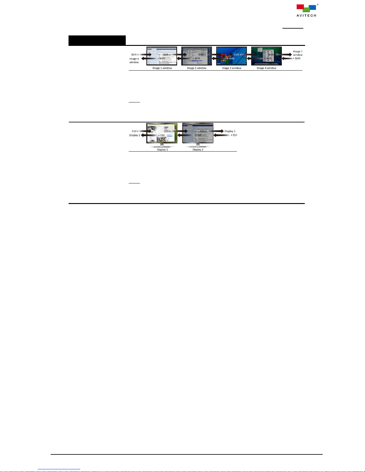
The following hot-keys are available when utilizing your Sequoia UHD under full screen Remote mode.
Keys
Shift + move the
mouse to the left/
right sides of the
window
For “Image” window control switching action upon pressing the Shift key
plus moving the mouse to the left/right sides of the window. Moving the
mouse from one “Image” window to the next transfers control from the
former window to the latter one.
Note: No “Image” window control switching action will occur when moving
the mouse to the top and bottom of the window, as well as moving the
mouse to the left and right sides of the window without pressing the Shift
key.
Ctrl + move the
mouse to the left/
right sides of the
monitor display
For monitor control switching action upon pressing the Ctrl key plus
moving the mouse to the left/right sides of the full screen display monitors.
Moving the mouse from one full screen monitor to the next transfers
control from the former window to the latter one.
Note: No full screen monitor control switching action will occur when
moving the mouse to the top and bottom of the monitor display, as well as
moving the mouse to the left and right sides of the full screen monitor
without pressing the Ctrl key.
Table 3-5 Hot-keys for “Image” Window Control Switching and Monitor Control Switching
42
Page 50
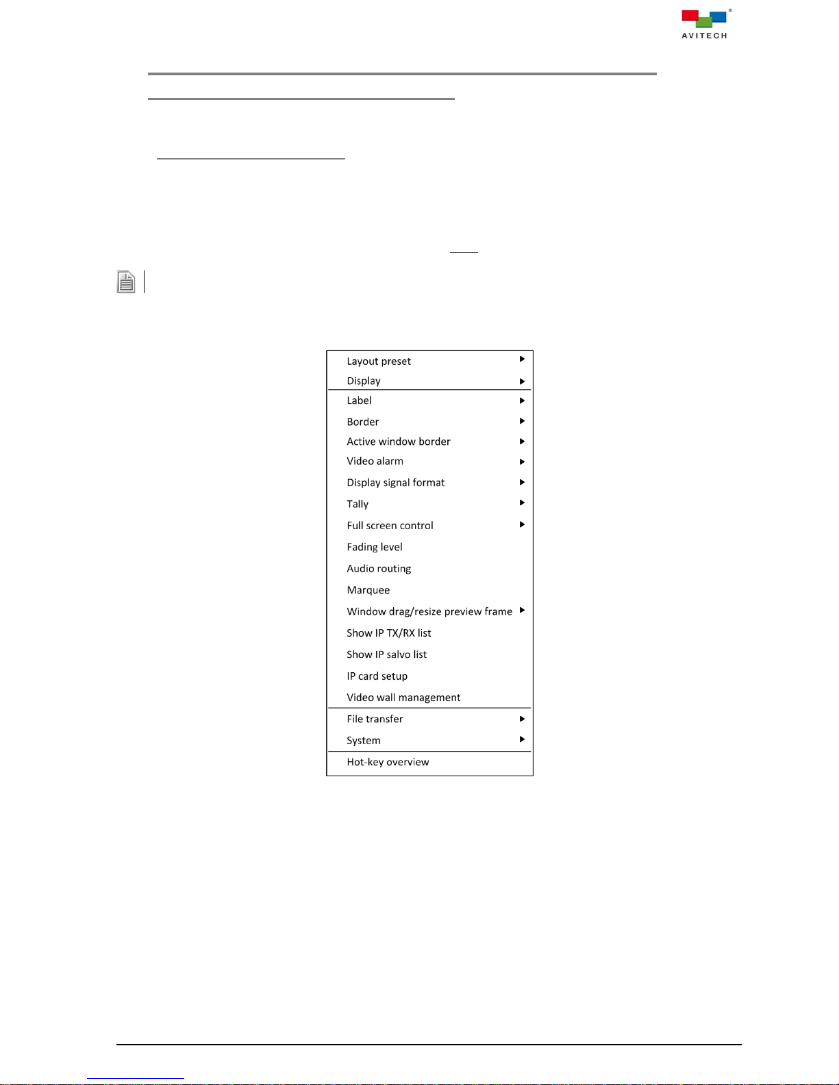
When the mouse right-click menu is open, mouse travel to the fifth computer’s monitor is not allowed.
4. Using the Mouse Right-click Menu, Changing the
Background Image and Salvo
4.1 Mouse Right-click Menu
The mouse right-click menu contains a collective of display and feature settings for the Sequoia UHD
such as customization of the user interface, presets save/load, alarm setup, audio routing, file transfer,
and hot-key hint. The menu, as shown in the figure below, can be called upon by right-clicking anywhere
on the on-screen interface when the Sequoia UHD is in Host mode (default window border color is gray).
This appendix discusses each item listed on the mouse right-click menu.
Figure 4-1 Mouse Right-click Menu
43
Page 51
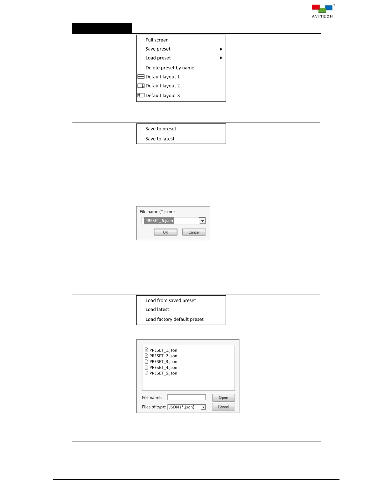
Right-click Menu
Layout preset
Select between a Full screen display, a quad display (Default layout 1 –
default); 1 (large) + 3 (smaller windows) display (Default layout 2); 3
(smaller windows) + 1 (large) display (Default layout 3) arrangement.
Save preset
Presets are files that contain user-configured display layouts with
adjusted settings. They allow users to keep their desired layouts for later
use without the need to repeatedly perform the same configuration.
Saved presets are stored to the Sequoia UHD's flash memory and can
be loaded anytime during the operation.
To save a preset, perform the following steps:
Step 1. Configure a new display layout and change settings if desired.
Step 2. Click Save to preset. A pop-up window with a default file name
will appear on the display.
Step 3. Edit the file name if desired (the file extension json will
automatically be added to the file name), and then click OK to
save the file. Special characters allowed are “_” (underline), “-“
(dash), and “.” (period) only. Repeat steps 1-3 for each
additional preset.
Alternatively, click Save to latest, and then click Load latest (refer to
Load preset). Your Sequoia UHD will immediately recall the display
layout that was last Save to latest.
Load preset
Load a preset previously created by clicking Load from saved preset,
and then select the desired file from the pop-up window.
Alternatively, click Load latest to load the window layout that was last
saved using Save to latest. This layout will also be the master layout
which gets loaded when your Sequoia UHD is powered on.
Or, click Load factory default preset for the default layout if desired.
44
Page 52
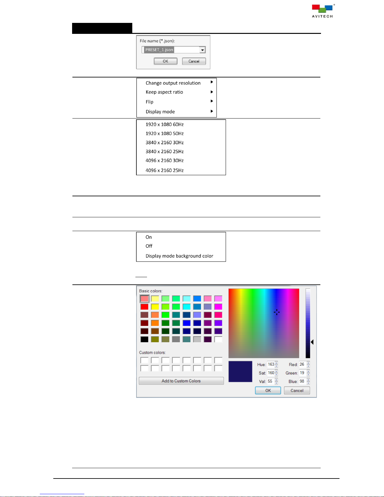
Right-click Menu
Delete preset
by name
Delete a saved preset file appearing on the list of the drop-down menu.
Display
Change output
resolution
Set the frame rate and display resolution of your Sequoia UHD's display.
Upon selecting a different frame rate or display resolution, a confirmation
message will appear. Click Yes to confirm.
Keep aspect
ratio
Confine each window to a fixed width-to-height ratio; a resized window will
also follow this aspect ratio. By default, the aspect ratio of a window is set
to match that of its corresponding video source. On – default.
Flip
Rotates the display 180-degrees. Off – default.
Display mode
Seamless switching of preset layout when using the and hot-keys in
Host operation mode by hiding all window’s label and signal format as well
as switching to the display mode background (next item). (Off – default)
Display mode
background
color
Change the background color when above item Display mode is set On
by performing the following: (default – RGB (32,32,32))
Step 1. In Basic colors on the upper left portion of the pop-up window,
click to select a desired color.
Step 2. Adjust the Hue, Saturation, and brightness Values.
Step 3. Adjust the Red, Green, and Blue values.
Step 4. Add the adjusted color to Custom colors by clicking the Add to
Custom Colors button (or directly drag a color from Basic
colors to Custom colors if no adjustment is needed).
Step 5. Repeat steps 1–4 for any additional color. Click to select a
45
Page 53

Right-click Menu
desired color from Custom colors to be the background color.
Label
Display label
Display/hide the label of a selected/all window(s). On – default.
Display IP UMD
Display/hide the under monitor display (UMD) of a selected/all window(s)
paired TX name. The IP UMD is shown beside the window’s label
(previous item) separated by the “/” symbol.
Define label
Define label: input a text string that will appear as the label of the selected
window (up to 31 characters).
Note: This user manual refers to the four windows based on their default
labels: Image 1, Image 2, Image 3 and Image 4 windows.
Font size: set the font size for a label’s text (14 to 60). 20 pixels – default
Font (default is RGB (229,229,229)) and Background color (default is
RGB (38,38,44)): change a label font’s / background color by performing
the following:
Step 1. In Basic colors on the upper left portion of the pop-up window,
click to select a desired color.
Step 2. Adjust the Hue, Saturation, and brightness Values.
Step 3. Adjust the Red, Green, and Blue values.
Step 4. Add the adjusted color to Custom colors by clicking the Add to
46
Page 54
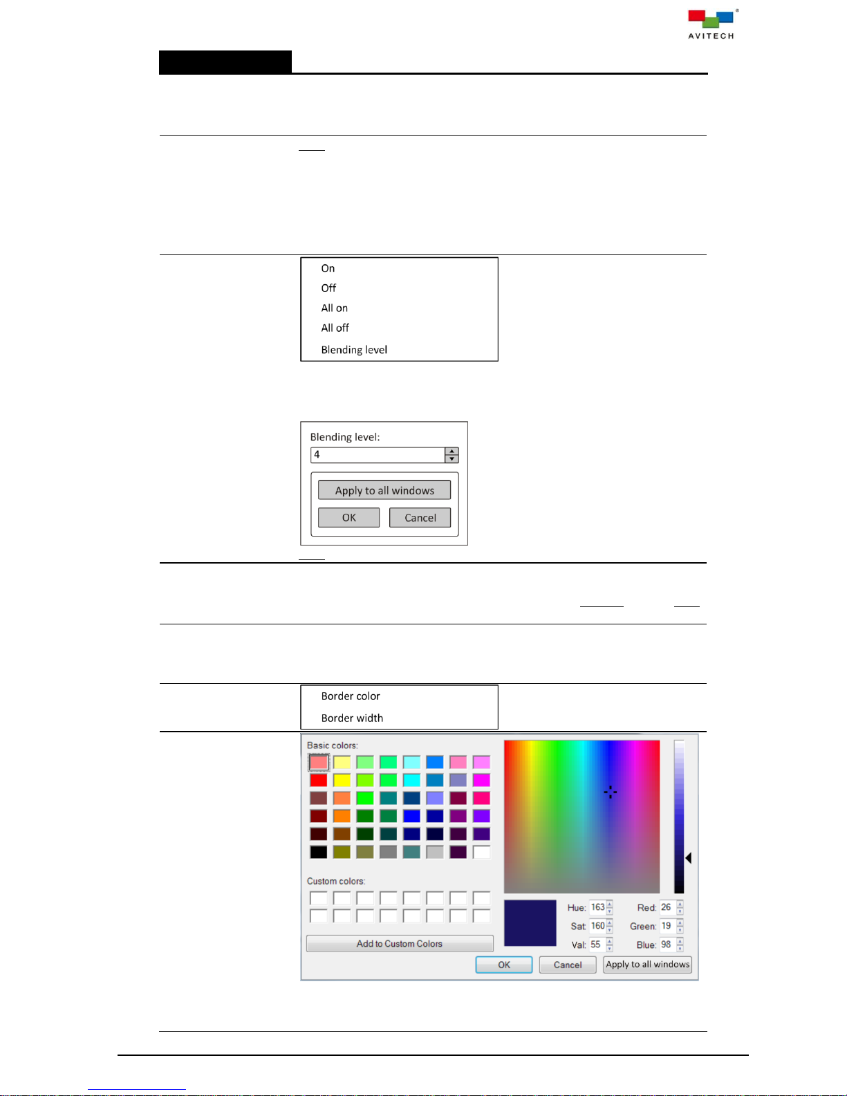
Right-click Menu
Custom Colors button (or directly drag a color from Basic
colors to Custom colors if no adjustment is needed).
Step 5. Repeat steps 1–4 for any additional color. Click to select a
desired color from Custom colors to be the label color.
Label outside
video
Note: This item is not shown by default. It is only available when the
succeeding item Label auto-hide is turned Off.
(On – default) When this item is turned On and previous item Keep
aspect ratio is On (default), then Image window will shrink to
accommodate the label bar. This means that if the quad layout formerly
fills up the whole monitor screen, then the Image window with Label
outside video set On will show the background image on both its left/
right.
Blending
Enable a window’s label to become transparent and blend into the image
displayed on the window (Off – default). Transparency level (0 ~ 7 where
7 is highest transparency level) can be set by using the arrow buttons on
the Blending level pop-up window (4 – default).
Note: The previous item’s Display label must be On.
Label auto-hide
Enable display of label for approximately five seconds on a window that
mouse cursor has just entered. Will also display the label of the window
for approximately five seconds upon switching from Remote mode to Host
mode. On – default
Display label
when full
screen
Enable the four windows to display their labels when set to full screen
(only effective when Display label is set All on). Off – default
Border
Border color
Change the border color of a selected window by performing the following:
Step 1. In Basic colors on the upper left portion of the pop-up window,
click to select a desired color. Default – RGB (77,81,89)
47
Page 55
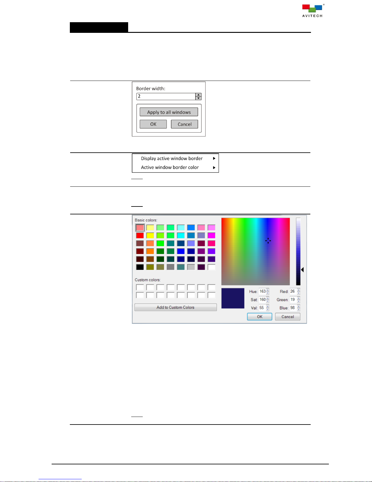
Right-click Menu
Step 2. Adjust the Hue, Saturation, and brightness Values.
Step 3. Adjust the Red, Green, and Blue values.
Step 4. Add the adjusted color to Custom colors by clicking the Add to
Custom Colors button (or directly drag a color from Basic
colors to Custom colors if no adjustment is needed).
Step 5. Repeat steps 1–4 for any additional color. Click to select a
desired color from Custom colors to be the border color.
Border width
Set the border width of a selected window (0, 2, 4 and 6).
On – default 2 pixels
Active window
border
Note: This item may not be available when SUHD-2HD is installed instead
of SUHD-KM.
Display active
window border
Enable the active window (“Surfer” or “Normal” (non-Surfer) mode) to
have a different border color (On – default 2 pixels).
Note: This item may not be available when SUHD-2HD is installed instead
of SUHD-KM.
Active window
border color
(Surfer mode) /
(Normal mode)
Set the border color of the active window in “Surfer” or “Normal”
(non-Surfer) mode by performing the following:
Step 1. In Basic colors on the upper left portion of the pop-up window,
click to select a desired color.
Step 2. Adjust the Hue, Saturation, and brightness Values.
Step 3. Adjust the Red, Green, and Blue values.
Step 4. Add the adjusted color to Custom colors by clicking the Add to
Custom Colors button (or directly drag a color from Basic
colors to Custom colors if no adjustment is needed).
Step 5. Repeat steps 1–4 for any additional color. Click to select a
desired color from Custom colors to be the border color.
Surfer mode: default – RGB (255,255,0)
Normal mode: default – RGB (255,0,0)
Note: This item may not be available when SUHD-2HD is installed instead
of SUHD-KM.
48
Page 56
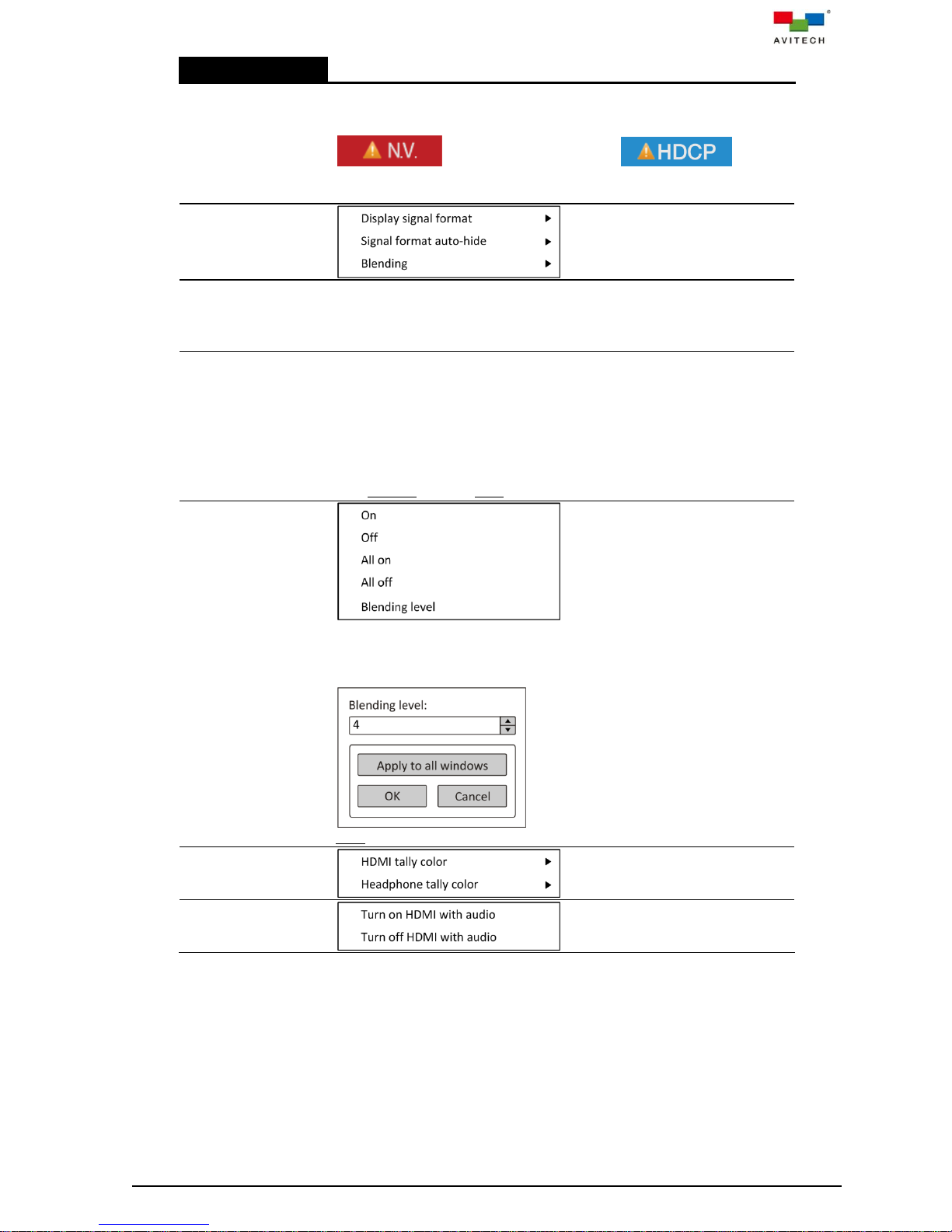
Right-click Menu
Video alarm
Enable video loss and HDCP not supported detection by displaying an
alert message(s) on any window that fails to receive video signal(s) or
input signal with HDCP content not supported by monitor. On – default
Font color: RGB (229,229,229) RGB (229,229,229)
Background color: RGB (191,25,25) RGB (31,157,229)
Display signal
format
Display signal
format
Display/Hide resolutions and frame rates of the video inputs currently
selected on the four windows. On – default
Font color: RGB (229,229,229)
Background color: RGB (191,25,25)
Signal format
auto-hide
Enable display of resolution and frame rate of the video input for
approximately five seconds on a window that mouse cursor has just
entered. When in full screen mode, display of resolution and frame rate of
the video input will occur upon moving mouse cursor to the upper left
portion (location of signal format) and will disappear once mouse cursor
has moved away. If mouse cursor stays in that position it will display for
approximately five seconds only. Will also display resolutions and frame
rates of the video inputs for approximately five seconds upon switching
from Remote mode to Host mode. On – default
Blending
Enable a signal format’s label to become transparent and blend into the
image displayed on the window (Off – default). Transparency level (0 ~ 7
where 7 is the highest transparency level) can be set by adjusting the
arrow buttons on the Blending level pop-up window (4 – default).
Note: The previous item Display Signal Format must be On.
Tally
HDMI tally color
49
Page 57
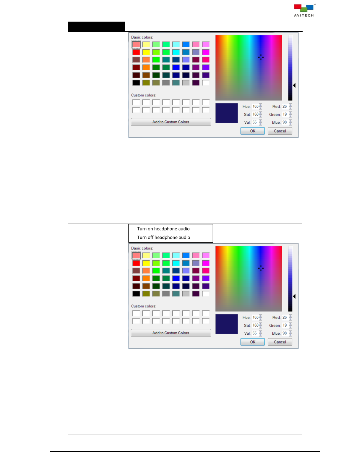
Right-click Menu
Set the left tally color when embedded audio output in HDMI signal is
turned on/off by performing the following:
Step 1. In Basic colors on the upper left portion of the pop-up window,
click to select a desired color.
Step 2. Adjust the Hue, Saturation, and brightness Values.
Step 3. Adjust the Red, Green, and Blue values.
Step 4. Add the adjusted color to Custom colors by clicking the Add to
Custom Colors button (or directly drag a color from Basic
colors to Custom colors if no adjustment is needed).
Step 5. Repeat steps 1–4 for any additional color. Click to select a
desired color from Custom colors to be the border color.
ON: default – RGB (0,255,0)
OFF: default – RGB (255,0,0)
Headphone
tally color
Set the right tally color when audio output from headphone is turned on/off
by performing the following:
Step 1. In Basic colors on the upper left portion of the pop-up window,
click to select a desired color.
Step 2. Adjust the Hue, Saturation, and brightness Values.
Step 3. Adjust the Red, Green, and Blue values.
Step 4. Add the adjusted color to Custom colors by clicking the Add to
Custom Colors button (or directly drag a color from Basic
colors to Custom colors if no adjustment is needed).
Step 5. Repeat steps 1–4 for any additional color. Click to select a
desired color from Custom colors to be the border color.
ON: default – RGB (0,255,0)
OFF: default – RGB (255,0,0)
50
Page 58

Right-click Menu
Full screen control
Note: This item may not be available when SUHD-2HD is installed instead
of SUHD-KM.
Automatically
enter Remote
mode
Enable a particular window in multi-display to enter Remote operation
mode upon using any of the below methods to switch to full screen view:
Ctrl + F# (F1 to F4) hot-keys, or
Click the icon (top-right corner of window)
Note: This item may not be available when SUHD-2HD is installed instead
of SUHD-KM.
Apply previous
layout upon
leaving Remote
mode
Enable a particular window to apply the prior to switching to full screen
view’s multi-display layout when using any of the below methods to return
to Host operation mode from Remote operation mode:
Pause/Break hot-key or control + option (Alt) + shift + p
Double-click the mouse scroll button
Note: This item may not be available when SUHD-2HD is installed instead
of SUHD-KM.
Fading level
Set the speed when an image window that is partly hidden from view is
selected to appear on the topmost level for seamless effect (one image
slowly fades from view while another takes its place). Use the slider (0~10
levels) where 0 is for instant switching while 10 corresponds to the slowest
fading speed.
Note: This option is not applicable for full screen window switching.
51
Page 59

Right-click Menu
Audio routing
Note: This item may
not be available
when SUHD-2HD is
installed instead of
SUHD-KM.
Set the Sequoia UHD audio-related parameters as well as audio signal
source routing to the audio ports:
HDMI output
Audio delay (default is enabled) range: 100 (13.63 milliseconds – default)
~ 8191 (687.86 milliseconds). Click Apply after adjustment.
Volume control for HDMI output is via the monitor display.
HDMI output allows you to select from the following audio input signal
sources that will output to the rear panel’s HDMI OUT port:
HDMI 1 (corresponds to the HDMI embedded audio signal entering the
rear panel’s HDMI IN 1 port)
HDMI 2 (corresponds to the HDMI embedded audio signal entering the
rear panel’s HDMI IN 2 port)
HDMI 3 (corresponds to the HDMI embedded audio signal entering the
rear panel’s HDMI IN 3 port)
HDMI 4 (corresponds to the HDMI embedded audio signal entering the
rear panel’s HDMI IN 4 port)
SDI cascade (corresponds to the rear panel’s CASCADE IN BNC
port)
PC 1 (corresponds to the audio signal entering via the rear panel’s
1 port)
PC 2 (corresponds to the audio signal entering via the rear panel’s
2 port)
PC 3 (corresponds to the audio signal entering via the rear panel’s
3 port)
PC 4 (corresponds to the audio signal entering via the rear panel’s
4 port)
PC 5 (corresponds to the audio signal entering via the rear panel’s
52
Page 60

Right-click Menu
IN port)
Cascade (corresponds to the rear panel’s CASCADE IN BNC port)
MIC (corresponds to the audio signal entering via the rear panel’s
port
Then click Apply for the selection to take effect.
The Mixer option allows you to have dual audio output. To achieve this,
make sure to connect a microphone to the rear panel’s port.
For example, if you wish to have a personal commentary of the video
output (with audio) being played in PC 1, just click the Mixer checkbox
and click Apply to enable simultaneous broadcast of embedded audio as
well as your own voice added to the mix. The ratio of the dual sound
volume is 50-50.
Note: Mixer is unavailable for HDMI 1 ~ HDMI 4 and SDI cascade.
Mute and then clicking Apply allows for instant volume suppression.
Note: The next item is applicable for Sequoia UHD+ / UHD/T+ only (for
cascade purposes).
SDI output allows you to select from the following audio input signal
sources that will output to the rear panel’s CASCADE OUT port:
HDMI 1 (corresponds to the HDMI embedded audio signal entering the
rear panel’s HDMI IN 1 port)
HDMI 2 (corresponds to the HDMI embedded audio signal entering the
rear panel’s HDMI IN 2 port)
HDMI 3 (corresponds to the HDMI embedded audio signal entering the
rear panel’s HDMI IN 3 port)
HDMI 4 (corresponds to the HDMI embedded audio signal entering the
rear panel’s HDMI IN 4 port)
SDI cascade (corresponds to the rear panel’s CASCADE IN BNC
port)
Then click Apply for the selection to take effect.
Mute and then clicking Apply allows for instant volume suppression.
Analog output
Audio delay (default is enabled) range: 100 (13.63 milliseconds – default)
~ 8191 (687.86 milliseconds). Click Apply after adjustment.
Note: Audio delay is only available for Headphone.
Digital input allows you to select from the following audio input signal:
HDMI 1 (corresponds to the HDMI embedded audio signal entering the
rear panel’s HDMI IN 1 port)
HDMI 2 (corresponds to the HDMI embedded audio signal entering the
rear panel’s HDMI IN 2 port)
HDMI 3 (corresponds to the HDMI embedded audio signal entering the
rear panel’s HDMI IN 3 port)
HDMI 4 (corresponds to the HDMI embedded audio signal entering the
rear panel’s HDMI IN 4 port)
SDI cascade (corresponds to the rear panel’s CASCADE IN BNC
port)
Then click Apply for the selection to take effect.
Headphone (corresponds to the rear panel’s port)
PC 1 / PC 2 / PC 3 / PC 4 / PC 5 output (corresponds to the rear panel’s
1 / 2 / 3 / 4 / IN ports respectively)
Cascade output (corresponds to the rear panel’s CASCADE OUT BNC
port)
The following are the available audio input signal sources for the above
items (Headphone / PC 1 / PC 2 / PC 3 / PC 4 / PC 5 output and
Cascade output):
Digital input – this will correspond to your choice of HDMI 1 ~ HDMI 4
or SDI cascade in the above item Digital input.
PC 1 (corresponds to the audio signal entering via the rear panel’s
1 port)
53
Page 61

Right-click Menu
PC 2 (corresponds to the audio signal entering via the rear panel’s
2 port)
PC 3 (corresponds to the audio signal entering via the rear panel’s
3 port)
PC 4 (corresponds to the audio signal entering via the rear panel’s
4 port)
PC 5 (corresponds to the audio signal entering via the rear panel’s
IN port)
Cascade (corresponds to the rear panel’s CASCADE IN BNC port)
MIC (corresponds to the audio signal entering via the rear panel’s
port)
Then click Apply for the selection to take effect.
For each of the above analog output ports, set the desired Volume level
(0 weakest ~ 10 loudest) or Mute it (for instant volume suppression). Click
Apply for any changes to take effect.
The Mixer option allows you to have dual audio output. To achieve this,
make sure to connect a microphone to the rear panel’s port.
For example, if you wish to have a personal commentary of the video
output (with audio) being played in PC 1, just click the Mixer checkbox to
enable simultaneous broadcast of embedded audio as well as your own
voice added to the mix.
Click Apply for any changes to Volume, Mixer and Mute to take effect.
Mixer volume
For each of the above digital and analog output ports that have the Mixer
option enabled, set the volume level (0 weakest ~ 255 loudest) of the
embedded audio as well as set the volume level (0 weakest ~ 255
loudest) of the microphone audio.
Then click Apply for any changes to take effect.
Analog input
When enabled, allows you to switch input source of Headphone from the
default SUHD-KM card’s 1/2/3/4 ports to the audio signal entering
the SUHD-IP card’s KVMoIP ports of Video 1/2/3/4.
Click Apply for the selection to take effect.
Note: Clicking OK will make any adjustments done above take effect and
allows you to exit audio setup. While clicking Cancel will nullify any
changes done even if the Apply button has been previously pressed.
Marquee
Click Enable to turn on scrolling text. The default position is on the upper
left area of the monitor display. To change position, use the mouse to click
and drag the marquee to a new position.
Note: Enabling the next item Window drag/resize preview frame (On)
would greatly assist you when changing the position of marquee.
54
Page 62

Right-click Menu
Click to select the type of marquee: Scrolling (travels from left to right) or
Blinking (intermittent) or Fixed (stationary).
Enter text to appear onscreen in the Content field, 60 characters
maximum (special characters other than letters and numerals allowed).
Width: 100 ~ 3840 (default is 1000 pixels)
Note:
1. Since the setting of x,y coordinates for Sequoia UHD is designed
towards a 4K display, this also includes the positioning for marquee.
The values (100 ~ 3840) for setting the Width will not change for a
1920×1080 resolution. This means that if you wish the marquee to
travel the whole width of your 1920 pixel display, then you must set it at
3840. Otherwise, if you set it at 1920 then marquee travel will only be
one-half of your 1920 pixel display.
2. If you wish the marquee text to be centered on the monitor display, do
not set the size at 3840 because this would cause the marquee to
occupy the maximum width of the 4K display.
Font size: 10 ~ 60 (default is 20)
Speed: 1 ~ 10 (default is 2)
Color
Change the text color by clicking the color box and performing the
following: (default – RGB (255,0,0))
Step 1. In Basic colors on the upper left portion of the pop-up window,
click to select a desired color.
Step 2. Adjust the Hue, Saturation, and brightness Values.
Step 3. Adjust the Red, Green, and Blue values.
Step 4. Add the adjusted color to Custom colors by clicking the Add to
Custom Colors button (or directly drag a color from Basic
colors to Custom colors if no adjustment is needed).
Step 5. Repeat steps 1–4 for any additional color.
Step 6. Click to select a desired color from Custom colors to be the text
color. Then click OK.
On the Marquee window, click Apply to apply the settings and then click
OK to exit.
Note:
1. The marquee function is normally used in Display mode (OSD turned
off). But when using marquee in non-Display mode, avoid positioning
marquee near the upper right portion of Image window as you would
be unable to access the pop-up selections. Or, try using Font size
lower than 30.
2. During Audio routing setup (previous item), marquee will temporarily
disappear from screen, but will reappear upon exiting Audio routing
setup.
3. During Image window resize/reposition, marquee will temporarily
disappear from screen, but will reappear upon finishing Image window
55
Page 63

Right-click Menu
resize/reposition.
4. It is not possible to position marquee on the lowest portion of the Image
window reserved for the auto-hide menu. System will automatically set
it above the auto-hide menu’s position.
5. During Remote operation mode, marquee will temporarily disappear
from screen, but will reappear upon returning to Host operation mode.
Window drag/resize
preview frame
By default, when repositioning (Image window and marquee) or resizing
(Image window), the exact location cannot be ascertained until after
letting go of the left mouse button. With Window drag/resize preview
frame turned On, the Image window’s and marquee’s outer frame would
appear onscreen to serve as a guide.
Show IP TX/RX list
Displays the IP TX List table (default position – lower left) showing all the
TX (transmitters); as well as displaying the IP RX List table (default
position – lower right) showing all the RX (receivers) detected by your
Sequoia UHD through the SUHD-IP as well as via the gigabit IGMP switch
connected to the IP port of SUHD-MB or SUHD-MB/IP.
Aside from the Name, Status and Channel ID columns, additional
columns showing the IP address, MAC (Media Access Control address)
and FW version can also be displayed by right-clicking anywhere on the
heading area and clicking the item(s) you want displayed.
To hide either or both IP TX List and IP RX List tables, click the
(upper right) of each window, or press Ctrl, Ctrl, M hotkey. To show both
tables again, click this item Show IP TX/RX list in the “right-click” menu,
or press Ctrl, Ctrl, M hotkey.
You can use the mouse to click-and-drag the IP TX List table and IP RX
List table to a new position or change its size by dragging on the corners.
To return both tables to its default size and position just click the Home
button.
You can also change the order of TX/RX appearing in the list by clicking
the title bar of each column to toggle between ascending/descending
order (triangle outline on right portion of each cell in the title bar).
To assign TX and RX pairing, the following methods can be used:
1. Use the mouse to drag a TX on top of an RX. Channel ID value for RX
will then follow the Channel ID value of TX. Or,
2. Click to highlight (select) a TX, then press Ctrl + C hotkey, then click to
highlight (select) a RX, then press Ctrl + V hotkey. To assign a TX to
multiple RXs, press Ctrl prior to clicking each RX and then press Ctrl +
V hotkey. Channel ID value for multiple RXs will then follow the
Channel ID value of TX. Or,
3. Right-click a TX and click Set TX channel in the menu. Copy the RX
Channel ID value that you wish to assign pairing.
Right-click menu for IP TX List:
56
Page 64
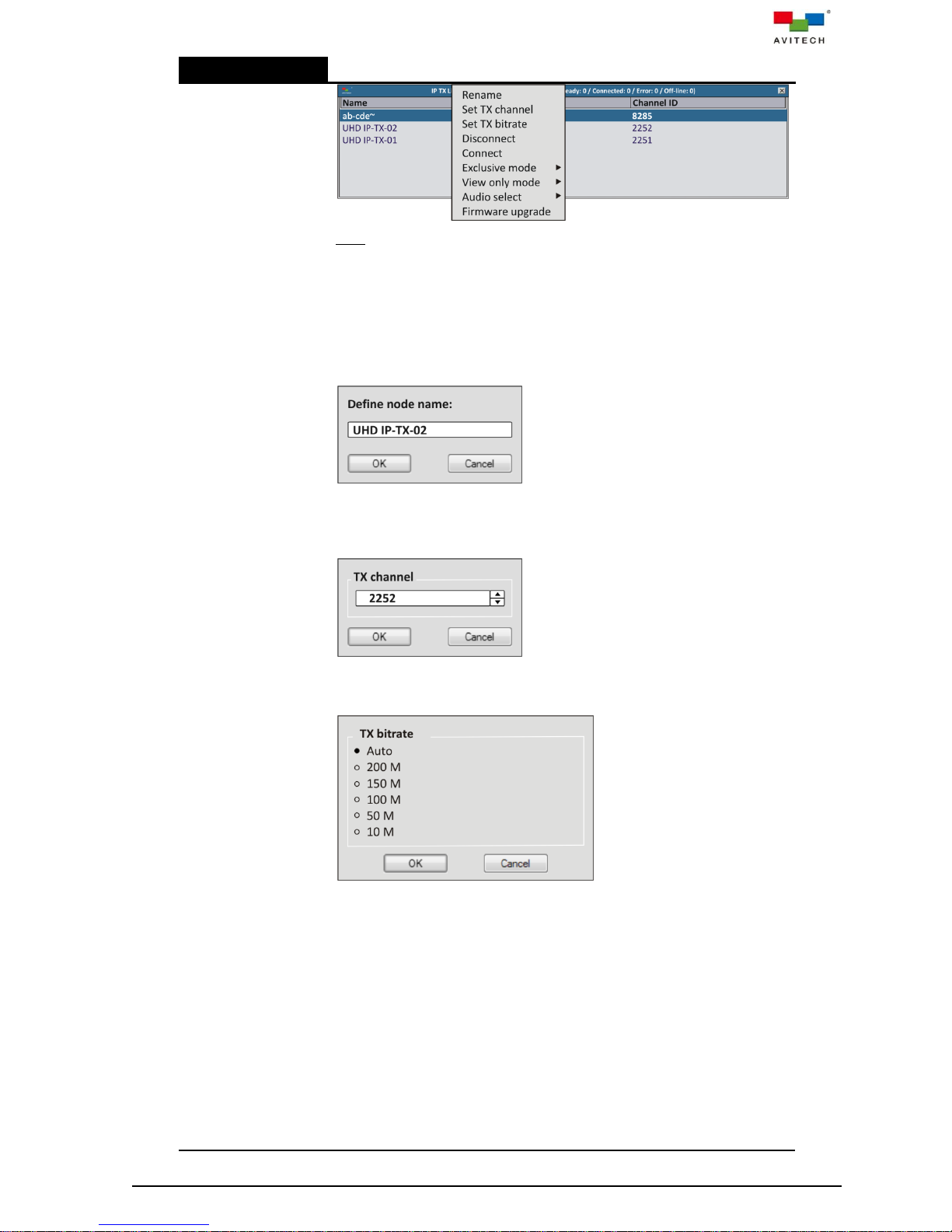
Right-click Menu
Note: The option Delete will only appear when you right-click a TX that
has an Off-line Status. Click Delete to remove a particular TX from the IP
TX List. Another way is to press Ctrl on your keyboard and use the
mouse to select a particular TX (continue selecting for multiple TXs), then
press Delete on your keyboard. Or, if you wish to delete all the TX that has
an Off-line Status from the IP TX List, press Ctrl + A and press Delete
on your keyboard.
Upon clicking Rename, the following window appears allowing you to
change the name of a particular TX appearing in the Name column.
Upon clicking Set TX channel, the following window appears allowing you
to change the channel number (0 ~ 9999) of a particular TX appearing in
the Channel ID column. You can copy the Channel ID number of a
particular RX to pair the TX to the RX.
Upon clicking Set TX bitrate, the following window appears allowing you
to set the video (with embedded audio) signal transfer rate from TX device
to RX device via IGMP switch.
Click Disconnect to terminate connection between a TX and your
Sequoia UHD. The Status column will change from Connected to
Stopped.
Click Connect to resume connection between a TX and your Sequoia
UHD.
The following Status for TX may be shown –
Ready = when a TX is not paired (assigned) to a RX.
Connected = when a TX is paired with a RX.
Booting = when the remote device connected to TX is currently
restarting.
Stopped = upon right-clicking a TX and selecting Disconnect.
Off-line = upon disconnection of network cable between a TX and the
gigabit IGMP switch or TX is powered-off.
Error = when this appears, try restarting the TX device and observe if it
will change its status. If after restarting it still shows Error, contact your
57
Page 65
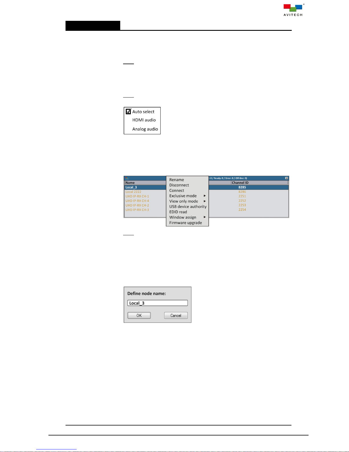
Right-click Menu
Avitech dealer for assistance.
Enabling Exclusive mode (default is Off) allows exclusive pairing
(routing) between one TX and one RX. Any other RX(s) routed to the
same TX would be suddenly disconnected upon enabling this option.
Note: To complete setup of Exclusive mode, the corresponding RX must
also enable Exclusive mode by right-clicking and turning it On.
Enabling View only mode (default is Off) restricts access to the remote
computer connected to the TX by allowing “view only” privilege (unable to
enter Remote mode to control the computer).
Note: To complete setup of View only mode, the corresponding RX must
also enable View only mode by right-clicking and turning it On.
Clicking Audio select allows you to set the audio source to allow HDMI
embedded audio source only, or Analog audio only, or Automatic
detection and select (default).
Clicking Firmware upgrade allows you to update the firmware of Pacific
X-IPT / X-IPTR / X-IPt detected by the Sequoia UHD.
Right-click menu for IP RX List:
Note: The option Delete will only appear when you right-click a RX that
has an Off-line Status. Click Delete to remove a particular RX from the IP
RX List. Another way is to press Ctrl on your keyboard and use the
mouse to select a particular RX (continue selecting for multiple RXs), then
press Delete on your keyboard. Or, if you wish to delete all the RX that
has an Off-line Status from the IP RX List, press Ctrl + A and press
Delete on your keyboard.
Upon clicking Rename, the following window appears allowing you to
change the name of a particular RX appearing in the Name column.
Click Disconnect to terminate connection between a TX and your
Sequoia UHD or another RX. The Status column will change from
Connected to Stopped.
Click Connect to resume connection between a TX and your Sequoia
UHD or another RX.
The following Status for RX may be shown –
Ready = whether a RX is paired (assigned) to a TX or not.
Booting = when the RX is currently restarting.
Stopped = upon right-clicking a RX and selecting Disconnect.
Off-line = upon disconnection of network cable between a RX (Sequoia
UHD KVMoIP port) and the gigabit IGMP switch.
Error = when this appears, try restarting the RX device and observe if it
will change its status. If after restarting it still shows Error, contact your
Avitech dealer for assistance.
Enabling Exclusive mode (default is Off) allows exclusive pairing
58
Page 66
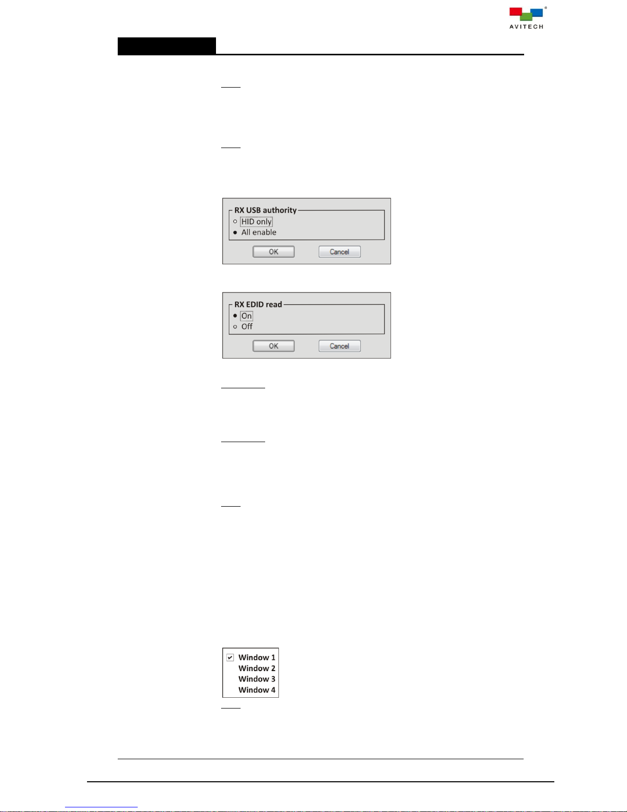
Right-click Menu
(routing) between one RX and one TX. Any other RX(s) routed to the
same TX would be suddenly disconnected upon enabling this option.
Note: To complete setup of Exclusive mode, the corresponding TX must
also enable Exclusive mode by right-clicking and turning it On.
Enabling View only mode (default is Off) restricts access to the remote
computer connected to the TX by allowing “view only” privilege (unable to
enter Remote mode to control the computer).
Note: To complete setup of View only mode, the corresponding TX must
also enable View only mode by right-clicking and turning it On.
Click USB device authority to toggle between restricting use of RX
type-A USB ports to connect to HID (human interface device keyboard/
mouse) only, or All enable (no restriction – default).
Click EDID Read to toggle automatic detection of EDID from the display
device(s).
On (default)
Scenario 1:
Upon switching a signal to a display device connected to RX, Sequoia
UHD will detect the preferred EDID of that display device and update the
information to the respective source (connected to TX). Source device will
then configure its output based on obtained EDID.
Scenario 2:
When routing a signal to multiple display devices routed from the same
TX, Sequoia UHD will assess the preferred EDID of each display device
and update the information to the respective source (connected to TX).
Source device will then configure its output based on the assessed EDID
and output at the optimum format supported by all the displays.
Note: Upon changing the existing routes, Sequoia UHD will re-assess the
EDID of each display device and update the information to the respective
source (connected to TX).
Off
The EDID of the connected display device (connected to RX) will no
longer be detected. The source device (connected to TX) will configure its
output based on the latest obtained EDID during which RX EDID read
was on.
Window Assign works in conjunction with the right-click menu item Label
> Display IP UMD (must be set On or All on). It allows you to assign the
TX name to be displayed on each of the four windows corresponding to
your Sequoia UHD’s SUHD-MB or SUHD-MB/IPT HDMI IN 1 / 2 / 3 / 4
ports routed from each of the two/four SUHD-IP HDMI OUT ports.
Note: Since each SUHD-IP HDMI OUT port can only be routed to one
SUHD-MB or SUHD-MB/IPT HDMI IN 1 / 2 / 3 / 4 port, then your choice of
Window 1 / 2 / 3 / 4 would be unique.
Clicking Firmware upgrade allows you to update the firmware of Pacific
X-IPTR / X-IPr / X-IPRW / X-IPRG detected by the Sequoia UHD.
59
Page 67
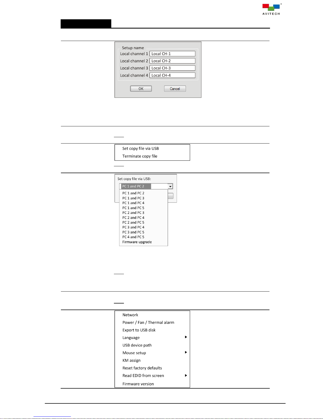
Right-click Menu
Show IP salvo list
Displays the Salvo List window showing all the mapping of sources and
destinations. See section 4.3 Salvo for details on using this feature.
IP card setup
Allows you to conveniently change all four names of your Sequoia UHD’s
SUHD-IP RX (receiver) appearing in the Name column. If you have only
one SUHD-IP card installed, depending if it is installed in the left slot or in
the right slot, then only Local channel 1 / 2 or Local channel 3 / 4 will be
available for setup.
Video wall
management
Note: Please refer to chapter 5 for details on using this feature.
File transfer
Note: This item may not be available when SUHD-2HD is installed instead
of SUHD-KM.
Set copy file
via USB
Select two USB ports corresponding to two connected computers as
endpoints for file and folder transfer. The Go! Bridge Utility will only initiate
when both of the selected ports are currently displayed on the two
windows. Refer to Appendix A for details.
Note:
1. Firmware upgrade is for manufacturer use only.
2. This item may not be available when SUHD-2HD is installed instead of
SUHD-KM.
Terminate copy
file
End the file/folder transfer.
Note: This item may not be available when SUHD-2HD is installed instead
of SUHD-KM.
System
60
Page 68
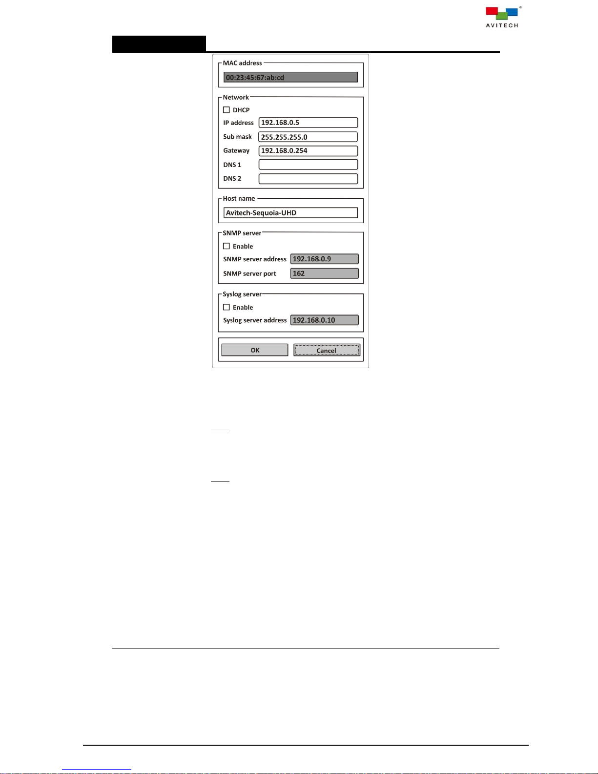
Right-click Menu
Network
Select Network to set up the network connection. The factory default IP
address is: 192.168.0.5. The Network settings must be manually entered.
This would be required for a network that uses fixed IP addresses. Upon
completing Network adjustment, locate OK on the bottom and click it.
This will apply the network setting to Sequoia UHD.
Note: The MAC address is a fixed address corresponding to the network
interface chip in your Sequoia UHD. The DHCP check box (if toggled on)
enables automatic assignment of an IP address to your Sequoia UHD;
you can choose to manually input an address or use the factory-default
one (192.168.0.5) for the IP address.
Note: The IP address must be changed for multiple Sequoia UHD setup.
The Subnet mask sets the number of IP addresses available in your local
area network; in other words, the number of remote computers supported
for remote monitoring. Make sure to press OK when done setting them.
Set the time server’s web address by entering the DNS 1 (preferred DNS)
to connect. Also, set the time server’s web address by entering the DNS 2
(alternated DNS) to connect.
SNMP is a protocol for collecting and organizing information about
managed devices, in this case the Sequoia UHD. The SNMP server fields
allow you to Enable it, specify the server’s IP address and port (server
pertains to the computer where operating information regarding Sequoia
UHD will be sent). The server should have the necessary application
installed to gather data using the SNMP protocol.
Aside from SNMP, Syslog is another system log management tool with its
own logging server software to help the administrator filter and focus on
operating information messages regarding Sequoia UHD. The Syslog
server fields allow you to Enable it and specify the server’s IP address.
61
Page 69
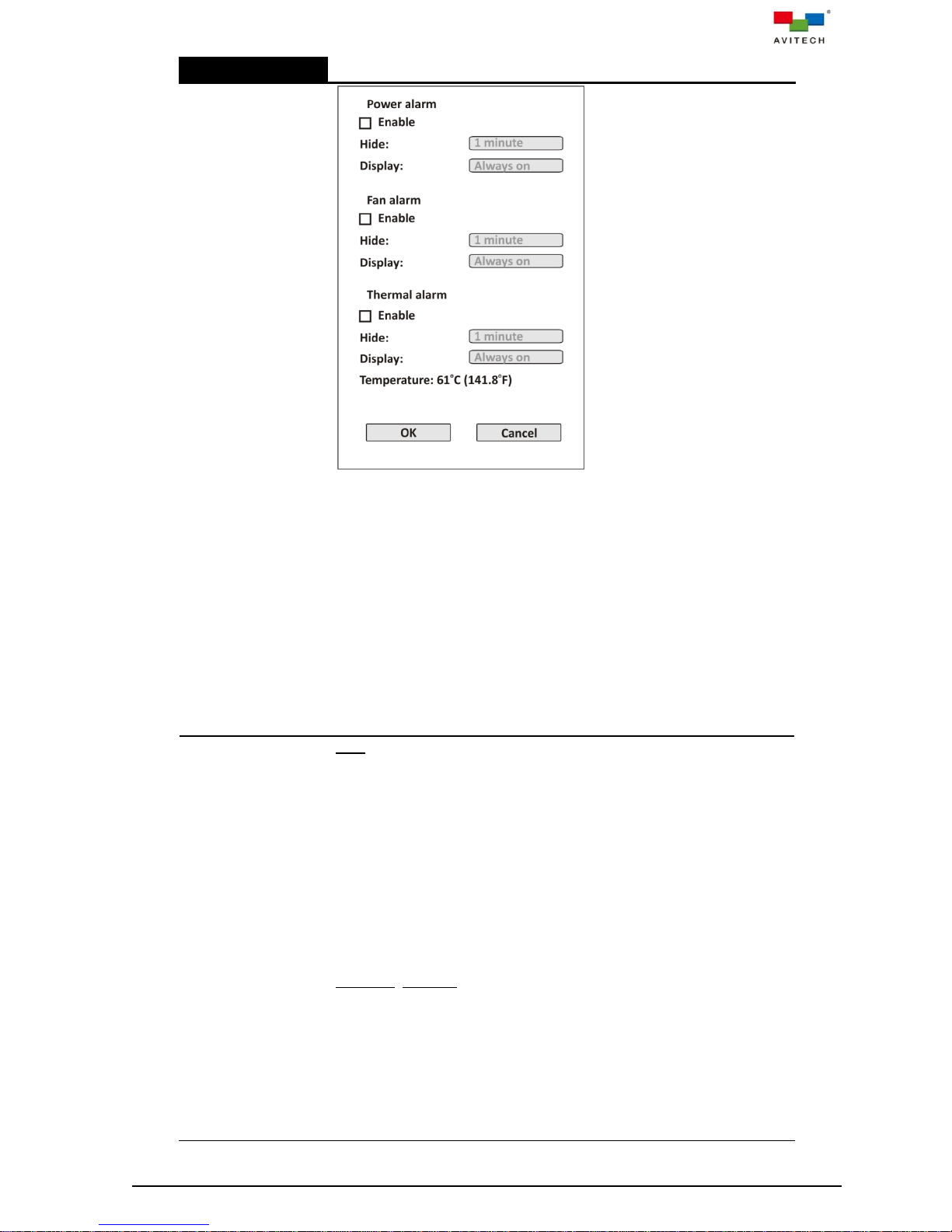
Right-click Menu
Power / Fan /
Thermal alarm
Set the display settings detail for the power/fan/temperature alerts:
enable/disable display warning; time duration when the warning is hidden
(1 minute, 5 minutes, 10 minutes, 30 minutes, 1 hour, 2 hours, 6
hours, 12 hours and 24 hours); and time duration when the warning
remains onscreen (10 seconds, 20 seconds, 30 seconds, 1 minute, 2
minutes, 5 minutes, 10 minutes, 30 minutes, 1 hour and always on).
For the power alert monitor to work properly, make sure that your Sequoia
UHD is connected to both power sources: 12 V DC / 9 A power adapter
and AC 100~240 V wall outlet. The power alert warning is activated when
either of the two power sources goes offline.
The fan alert warning is activated when any of the six cooling fan inside
the Sequoia UHD is not working properly.
The thermal alert warning is activated when any of the FPGA chips inside
the Sequoia UHD reaches a temperature of 86 oC or higher.
The operating temperature of the Sequoia UHD is also displayed (Celcius
and Fahrenheit).
Export to USB
disk
Note: This item is not shown by default. It is only available when upon
unplugging the keyboard connected to the SUHD-MB USB type-A port on
the rear panel of the Sequoia UHD and inserting a USB thumb drive. And
then clicking “Cancel” when the file selector window appears.
Upon clicking this command, allows you to backup to a USB thumb drive
(supports FAT32 and NTFS formats only) the presets that was previously
stored using the Layout preset > Save preset > Save to preset and
Save to latest commands. Or press Ctrl + S before inserting the USB
thumb drive. The default AT-Sequoia-4H-UHD-Backup.bin file will be
created and saved in the root directory of your USB thumb drive. If you
wish to make a distinction between the backup file saved previously and a
backup file to be saved in a later time, you can add for example
“11102017” after the word “Backup” in the file name (i.e.
AT-Sequoia-4H-UHD-Backup-11102017.bin).
Important: DO NOT alter the file name AT-Sequoia-4H-UHD-Backup as
this will cause the backup file to become unacceptable to the system. You
are only allowed to add acceptable characters after “Backup”.
To load the backup BIN file to the Sequoia UHD, insert the USB thumb
drive into the SUHD-MB USB type-A port on the rear panel of the Sequoia
UHD. When the file selector window appears, locate and select the BIN
file and click Open. A “warning” message will appear asking you if you
really wish to proceed. Click “Cancel” to abort or “OK” to proceed. The
progress of updating will be shown (progress bar). You will be prompted to
reboot the Sequoia UHD to complete the whole process.
62
Page 70
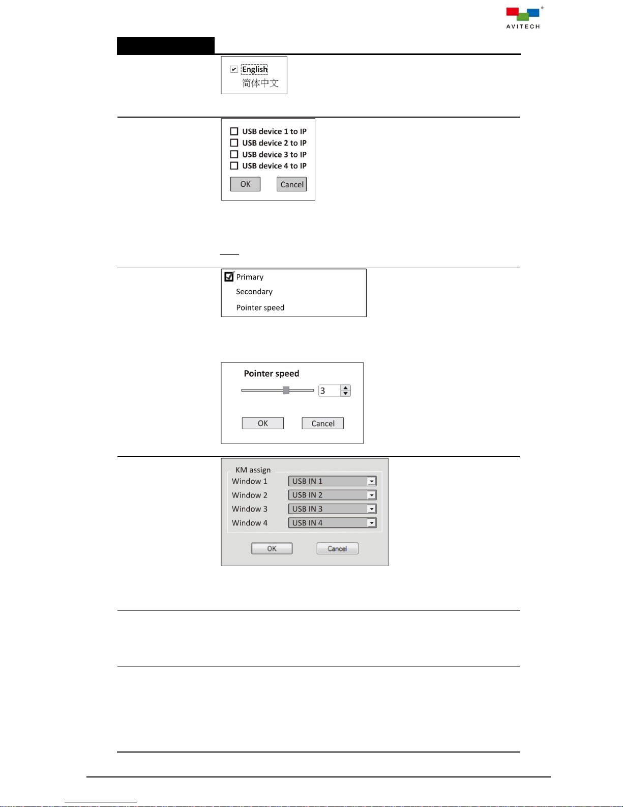
Right-click Menu
Language
Toggle between English (26 alphabets) and Simplified Chinese (Mandarin
Pinyin) input methods and user interface.
USB device
path
When enabled, allows you to switch input source of USB K/M (keyboard/
mouse) from the default SUHD-KM card’s USB IN 1/2/3/4 ports to the
USB K/M signal entering the SUHD-IP card’s KVMoIP ports of Video 1/2/
3/4.
Note: This item may not be available when SUHD-2HD is installed instead
of SUHD-KM.
Mouse setup
Select Primary to make the left mouse button the one you use for primary
functions such as selecting and dragging.
Select Secondary to make the right mouse button the one you use for
primary functions such as selecting and dragging.
Select the mouse pointer speed: 0 (fastest) ~ 5 (slowest). Default is 3.
KM assign
Allows you to bundle video signal with keyboard/mouse control so that a
specific input port in SUHD-MB is routed through the corresponding USB
port on the SUHD-KM (i.e. HDMI IN 1, 2, 3, 4 is bundled with USB IN 1, 2,
3, 4 respectively).
Reset factory
defaults
Reset your Sequoia UHD’s right-click menu settings to its factory-default
state. Upon resetting your Sequoia UHD to its factory-default state, your
previously saved presets stored in the Sequoia UHD's flash memory will
be automatically removed; make sure to have your files saved externally
before resetting the Sequoia UHD to the factory-default state.
Read EDID from
screen
Toggle automatic detection of EDID from the display device.
On (default)
Upon switching a signal to a display device connected to HDMI OUT port
of SUHD-MB / SUHD-MB/IPT, Sequoia UHD will detect the preferred
EDID of that display device and update the information to its source.
Source device will then configure its output based on obtained EDID.
Off
63
Page 71
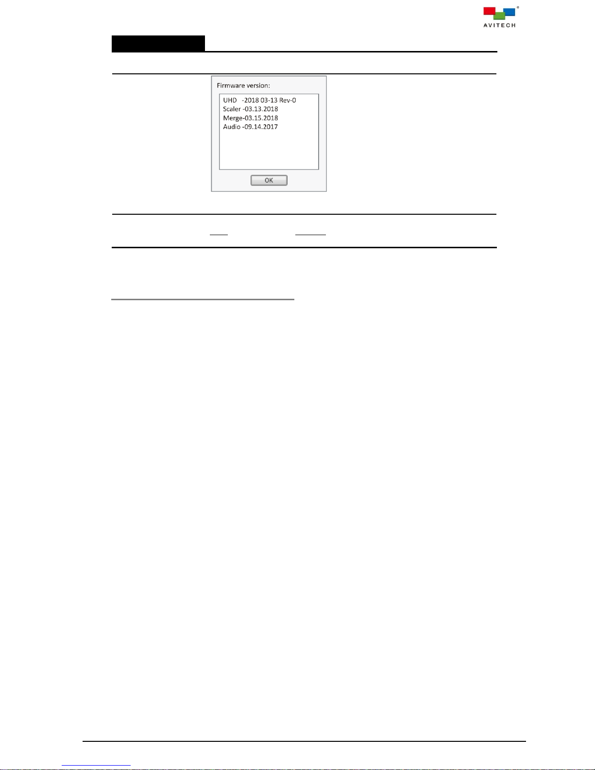
Right-click Menu
The EDID of the connected display device will no longer be detected and
Sequoia UHD will output at 4K.
Firmware
version
Display information of the firmware version and associated chipset
embedded in your Sequoia UHD.
Hot-key overview
Displays a table showing the available hot-keys that can be used during
Host operation mode, Remote operation mode as well as for utilizing your
Sequoia UHD on the fifth computer.
Table 4-1 Mouse Right-click Menu Description
4.2 Changing the Background Image
The Sequoia UHD allows you to set the background image of the preview area of the in-system GUI. A
dark backdrop with the Avitech logo serves as the default background image. Select an image file that
will serve as the background image (allowed file formats are: BMP/JPEG/JPG/PNG only; acceptable
image resolution up to 4K).
The following steps show how to replace the background image:
Step 1. Save the image file to a USB thumb drive (supports FAT32 and NTFS formats only).
Step 2. Detach the keyboard connected to the SUHD-MB USB type-A port on the rear panel of the
Sequoia UHD.
64
Page 72
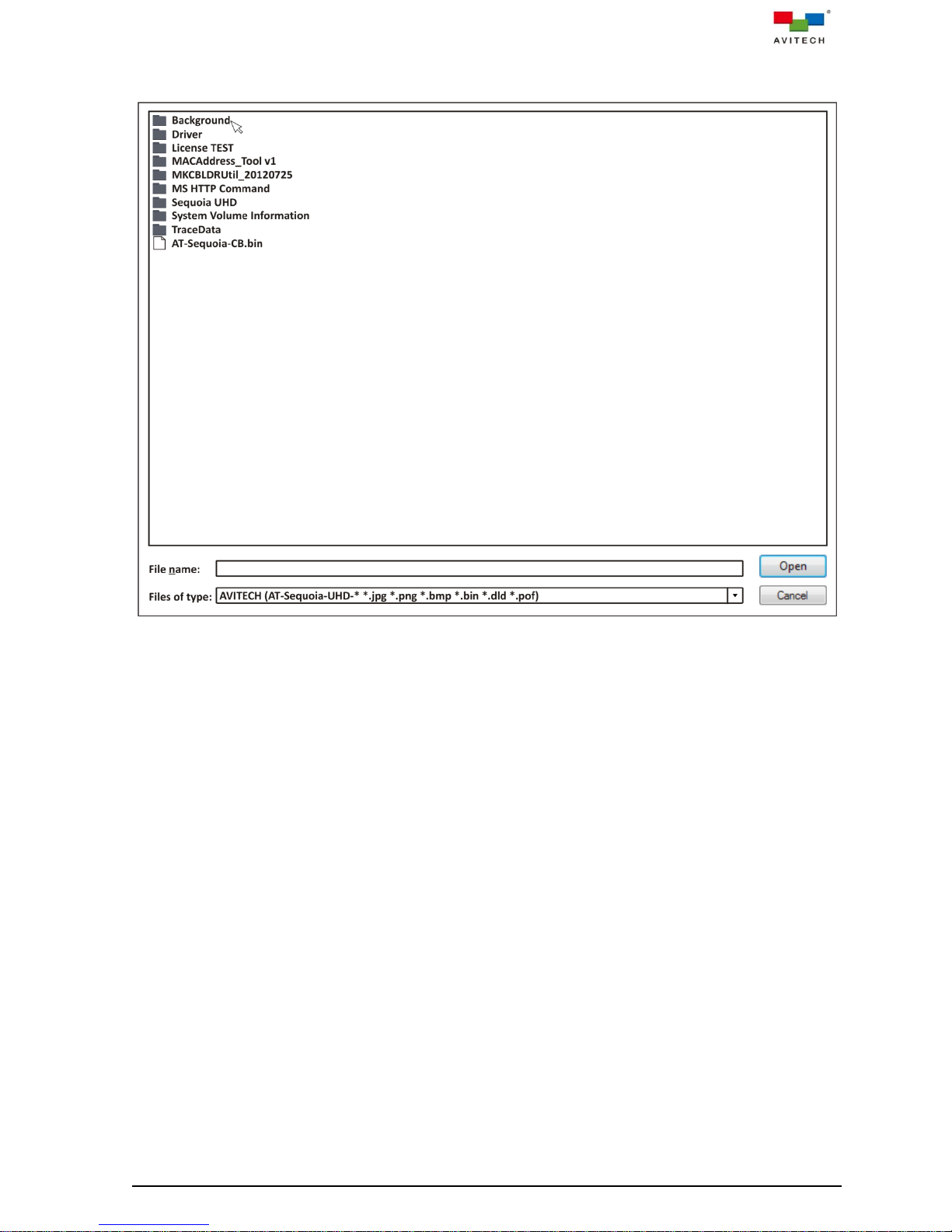
Step 3. Insert the thumb drive into the just vacant USB type-A port. The following sample screen will
automatically appear.
Figure 4-2 File Selector Window
Step 4. Navigate to the folder containing your image file.
Step 5. Select the image file.
Step 6. Click “Open”.
Step 7. Click “OK” to confirm and the progress of updating will be shown (progress bar). The GUI’s
background will be updated.
65
Page 73

4.3 Salvo
4.3.1 Configure a Salvo
A salvo is a mapping of sources and destinations. It is configured and saved in the Sequoia UHD and
can be applied by a single "Trigger salvo" command. Each “salvo” stores a group of pre-defined
routings. With a single command it reconfigures multiple routes for a number of sources and
destinations all at once. Salvos can be saved and instantly recalled by clicking the corresponding Salvo
button.
To edit a salvo, perform the following steps:
Step 1. Press Ctrl, Ctrl, S on your keyboard or via the right-click menu’s Show IP Salvo list; the Salvo
List page will appear.
Figure 4-3 Salvo List Page
Step 2. Right-click anywhere on the blank Salvo List page and click Add salvo.
Figure 4-4 Creating a New Salvo
66
Page 74

Step 3. Assign a salvo name and click OK.
Figure 4-5 Define Salvo Name
Step 4. Method 1: drag and drop method
After designating the name of the salvo, next assign the routing. Drag a TX (i.e. TX_1) on top of
the salvo name (i.e. Opening salvo). Then drag an RX (i.e. UHD IP-RX CH-1) on top of the TX.
We can drag another RX (i.e. Local_3) on top of the same TX.
Method 2: hot-keys method
Use the mouse to click the TX (i.e. TX_1) to select it (highlight). On your keyboard press Ctrl +
C. Click the salvo name (i.e. Opening salvo). Then press Ctrl + V. Notice that TX_1 appears
beneath “Opening salvo.”
Click the RX (i.e. UHD IP-RX CH-1) to select it (highlight). On your keyboard press Ctrl + C.
(To assign more than one RX to a TX, on your keyboard press Ctrl, then use the mouse to click
another RX.) Click the TX (i.e. TX_1). Then press Ctrl + V. Notice that UHD IP-RX CH-1
appears beneath “Opening salvo.”
Click another RX (i.e. Local_3) to select it (highlight). On your keyboard press Ctrl + C. Click the
TX (i.e. TX_1). Then press Ctrl + V. Notice that Local_3 appears beneath “Opening salvo.”
Figure 4-6 Assign Routing to a Salvo
Step 5. After creating (a) salvo(s), right-click the selected salvo and click Trigger salvo to route a
grouping of source and destination(s).
Figure 4-7 Trigger (Execute) a Salvo
. You can also delete or rename the selected salvo by clicking Delete salvo or Rename salvo
respectively.
67
Page 75

. You can also delete a specific TX or a specific RX from a salvo by right-clicking it and clicking
Delete TX or Delete RX on the menu respectively. Then, click OK to confirm. Deleting a TX from
a salvo would remove the TX and the corresponding RX routed to it. While deleting a RX from a
salvo would just remove that RX.
Figure 4-8 Delete a TX/RX From a Salvo
68
Page 76

5. Video Wall Management
1. One Sequoia UHD – (SUHD-2HD card) can do 2×2 wall display (refer to the example in section 2.3.3
“Sequoia UHD to 2×2 Video Wall with Pacific X-IPT Connected via Gigabit IGMP Switch” for hardware
connections).
2. Two Sequoia UHDs – (two SUHD-2HD cards) can do 2×3 wall display (refer to the example in section 2.3.4
“Two Sequoia UHD to 2×3 Video Wall with Two Pacific X-IPT Connected via Gigabit IGMP Switch” for
hardware connections).
Sequoia UHD list
Shows the detected Sequoia UHD without SUHD-2HD card in blue text
and showing the detected Sequoia UHD with SUHD-2HD card in red
text (name and IP address).
Video wall
connection
diagram
To create a video wall:
Step 1. Right-click here and then click Add.
Step 2. Choose the type of video wall (configuration) and define the
wall name.
Step 3. Drag a detected SUHD-2HD card from the list when creating a
2×2 wall display. Or,
Drag the two detected SUHD-2HD cards from the list when
creating a 2×3 wall display. Or,
Drag up to six detected Sequoia UHD without SUHD-2HD card
from the list when creating up to six 1×1 wall display. Or,
Drag up to four detected Sequoia UHD+ with SUHD-2HD card
from the list when creating a 3×4 wall display.
TX list
Shows the detected TXs as possible video source for assigning to the
video wall windows, as well as a snapshot of the detected TX displays.
Click any of the TX to update its snapshot as well as any RX window in
the video wall design area paired to this particular TX.
5.1 Basic Video Wall Management Setup
Upon clicking Video wall management, the following page appears.
Figure 5-1 “Video Wall Management” Screen Components
69
Page 77

Video wall
design area
Add/remove/move windows and change its size in this area.
A 2×3 wall display is comprised of a 2×2 (maximum of four windows)
plus a 2×1 wall (maximum of four windows) for a maximum of eight
windows.
A 1×1 wall display is comprised of maximum six 1×1 walls.
A 3×4 wall display is comprised of two 2×2 (maximum of eight windows)
plus two 1×2 wall (maximum of eight windows) for a maximum of 16
windows.
Note:
1. For a 2×3 wall display, a window that straddles both 2×2 and 2×1 wall
will be counted as one window for each wall.
For a 3×4 wall display, a window that straddles both 2×2 and 2×2
wall; or both 1×2 and 1×2 wall; or both 2×2 and 1×2 wall will be
counted as one window for each wall.
2. Adding a fifth window on either wall will cause the first window
created or,
from out of the four windows, the first window that your mouse cursor
has clicked will become hidden from view by the system.
But upon removing the newly added window, system will cause the
hidden window to reappear on the same position/size prior to its
being hidden.
3. An image cannot straddle two 1×1 windows (cannot go beyond its
border).
User-defined
preset 1/2/3,
Save preset,
Load preset,
Delete preset,
Close, Save,
Take, and
Genlock buttons
User-defined preset 1/2/3 = each represents a saved preset. A preset is
a file that contains user-designed window layout for a wall
configuration. Users can have multiple presets stored in the Sequoia
UHD for future references, but only the latest three presets saved can
be loaded from these three buttons as shortcuts (only presets saved by
using the Save preset button). When the number of presets reaches or
exceeds three, any new preset saved will replace the old one (in the
order of preset 1, 2, and 3).
Save preset = saves to Sequoia UHD memory the configured window
layout for future recall.
Load preset = select from a list of previously saved preset(s) to be
loaded as the window layout.
Delete preset = select a previously saved preset to be removed from
memory.
Close = exit the Video wall management page.
Save = saves the Video wall management page’s configuration into
Sequoia UHD for automatic recall of settings upon its next power on.
Take = to confirm and execute the video wall’s switching/routing action.
Genlock = allows the video output of one source (coming from the REF
OUT port of Sequoia UHD 1), or a specific reference signal from a
signal generator, to be used to synchronize another source(s) together
70
Page 78

(to REF IN port of Sequoia UHD 2). The aim in video applications is to
ensure the coincidence of signals in time at a combining or switching
point. When video sources are synchronized in this way, they are said
to be generator-locked, or genlocked.
Table 5-1 Video Wall Management Page Components
To create and set a 1×1 or 2×3 or 3×4 wall display, perform the following steps:
Step 1. On the video wall connection diagram area, right-click anywhere and then click Add.
Figure 5-2 Add Video Wall
Step 2. The Define wall name dialog box will appear, select 1 × 1 or 2 × 3 or 3 × 4 and assign a wall
name. Then click OK.
Figure 5-3 Select 1×1 or 2×3 or 3×4 Wall Display and Assign a Name
71
Page 79

The wall name and wall configuration will be shown.
Figure 5-4 Wall Name and Wall Configuration Defined
Step 3. For 1×1 Wall Display
Drag five (maximum up to six) Sequoia UHD (i.e. IP:192.168.0.181 up to 192.168.0.185) to the
wall name (A (1 × 1)) you just created. Notice that as you drag each Sequoia UHD to the wall
name it would then create a branch from the wall name.
Figure 5-5 Assign the Five Sequoia UHD to the Wall
72
Page 80
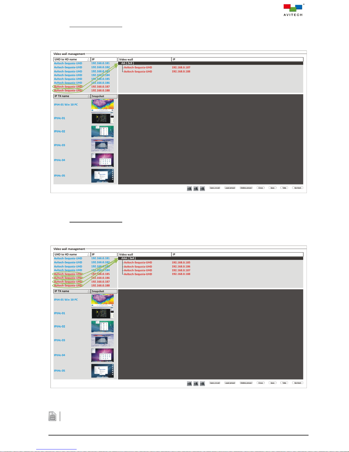
For 2×3 Wall Display
The Sequoia UHD branch can be deleted anytime by right-clicking it and selecting (clicking) Delete.
Drag the two Sequoia UHD/T+ (i.e. IP:192.168.0.187 and 192.168.0.188) to the wall name (AA
(2 × 3)) you just created. Notice that as you drag each Sequoia UHD/T+ to the wall name it
would then create a branch from the wall name.
Figure 5-6 Assign the Two Sequoia UHD/T+ to the Wall
For 3×4 Wall Display
Drag the four Sequoia UHD+ (i.e. IP:192.168.0.185 up to 192.168.0.188) to the wall name (AAA
(3 × 4)) you just created. Notice that as you drag each Sequoia UHD+ to the wall name it would
then create a branch from the wall name.
Figure 5-7 Assign the Four Sequoia UHD+ to the Wall
73
Page 81

Step 4. Double-click the wall name.
Figure 5-8 Double-click the Wall Name
For 1×1 Wall Display
The template for a 1×1 wall that comprises six displays appear.
Figure 5-9 Six Displays Form an 1×1 Wall
74
Page 82
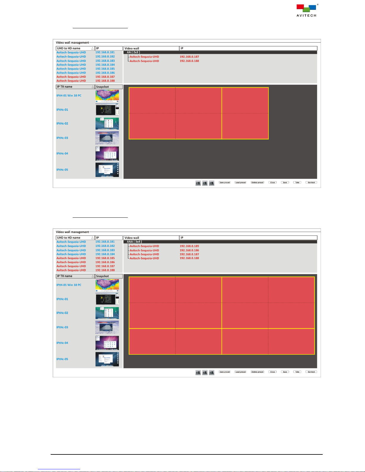
For 2×3 Wall Display
The template for a 2×3 wall that comprises a 2×2 wall beside a 2×1 wall appears.
Figure 5-10 2×2 Wall Plus 2×1 Wall to Form a 2×3 Wall
For 3×4 Wall Display
The template for a 3×4 wall that comprises two 2×2 wall on top of two 1×2 wall appears.
Figure 5-11 Two 2×2 Wall on Top of Two 1×2 Wall to Form a 3×4 Wall
75
Page 83
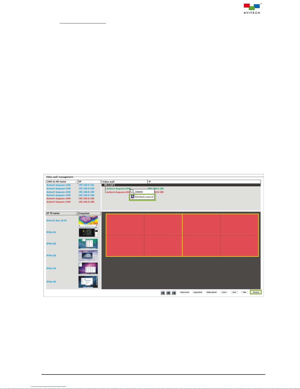
Set Genlock Source
Except for a 1×1 wall (because an image cannot straddle two 1×1 windows (cannot go beyond
its border)), all other wall configuration can set the genlock source to allow the video output of
one source (coming from the REF OUT port of Sequoia UHD 1), or a specific reference signal
from a signal generator, to be used to synchronize another source(s) together (to REF IN port of
Sequoia UHD 2); and so forth. The aim in video applications is to ensure the coincidence of
signals in time at a combining or switching point. When video sources are synchronized in this
way, they are said to be generator-locked, or genlocked.
To set the genlock source:
Designate a Sequoia UHD to be the reference signal (i.e. Sequoia UHD with IP address:
192.168.0.185). Make sure that the BNC cable is connected to the REF OUT port.
Connect the other end of the BNC cable to the REF IN port of the Sequoia UHD with IP
address: 192.168.0.186.
Right-click this Sequoia UHD (IP address: 192.168.0.185) and select (click) Genlock
source. Notice that a checkmark appears signifying that it has been enabled. The text color
for this particular branch of Sequoia UHD changes to “green” signifying that this is the
genlock source device.
Click the Genlock button (on the lower right). Notice on your wall display that the monitors
connected to the Sequoia UHD as genlock source will flicker and then stabilize. Then the wall
display that the monitors connect to the next Sequoia UHD will flicker and then stabilize. This
phenomenon can be observed when additional Sequoia UHD is daisy-chained in this
manner.
This concludes setting the genlock source.
Figure 5-12 Set Genlock Source for 2×4 Wall
76
Page 84
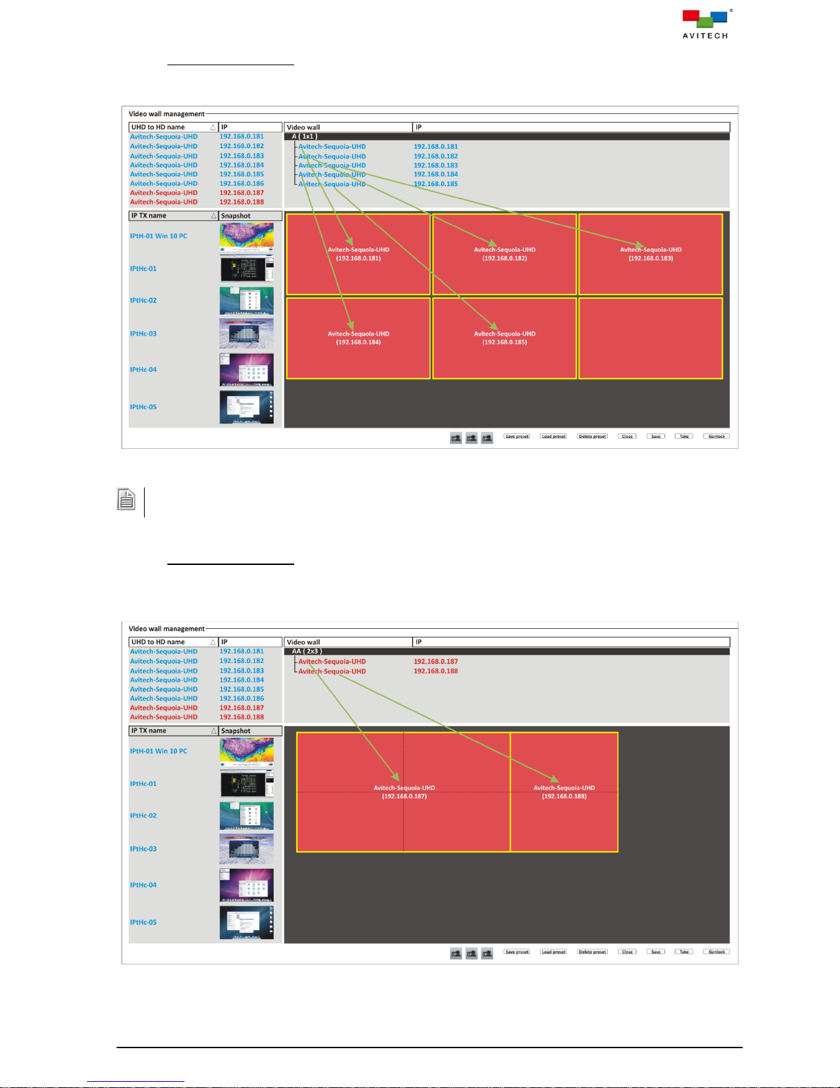
Step 5. For 1×1 Wall Display
To remove a Sequoia UHD that has been assigned to a display, right-click anywhere on the display and click
Remove device on the menu that appears. This applies to a 2×3 and 3×4 wall display as well.
Drag a Sequoia UHD to each of the five displays. Notice that the name and IP address of each
Sequoia UHD is displayed in the center of each display.
For 2×3 Wall Display
Drag a Sequoia UHD/T+ to the 2×2 wall template and the other Sequoia UHD/T+ to the 2×1 wall
template. Notice that the name and IP address of each Sequoia UHD/T+ is displayed in the
center of each wall template.
Figure 5-13 Drag a Sequoia UHD to Each Display
Figure 5-14 Drag Each Sequoia UHD/T+ to the Wall Template
77
Page 85
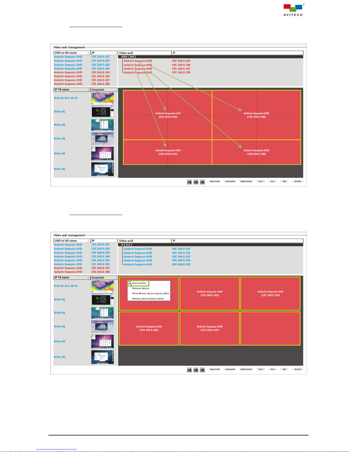
For 3×4 Wall Display
Drag a Sequoia UHD+ to each of the four displays. Notice that the name and IP address of each
Sequoia UHD+ is displayed in the center of each wall template.
Figure 5-15 Drag Each Sequoia UHD+ to the Wall Template
Step 6. For 1×1 Wall Display
On the 1×1 wall template, right-click anywhere on a display and then click Add window.
Perform the same step to each of the other four displays.
Figure 5-16 Add Window to the 1×1 Wall Template
78
Page 86
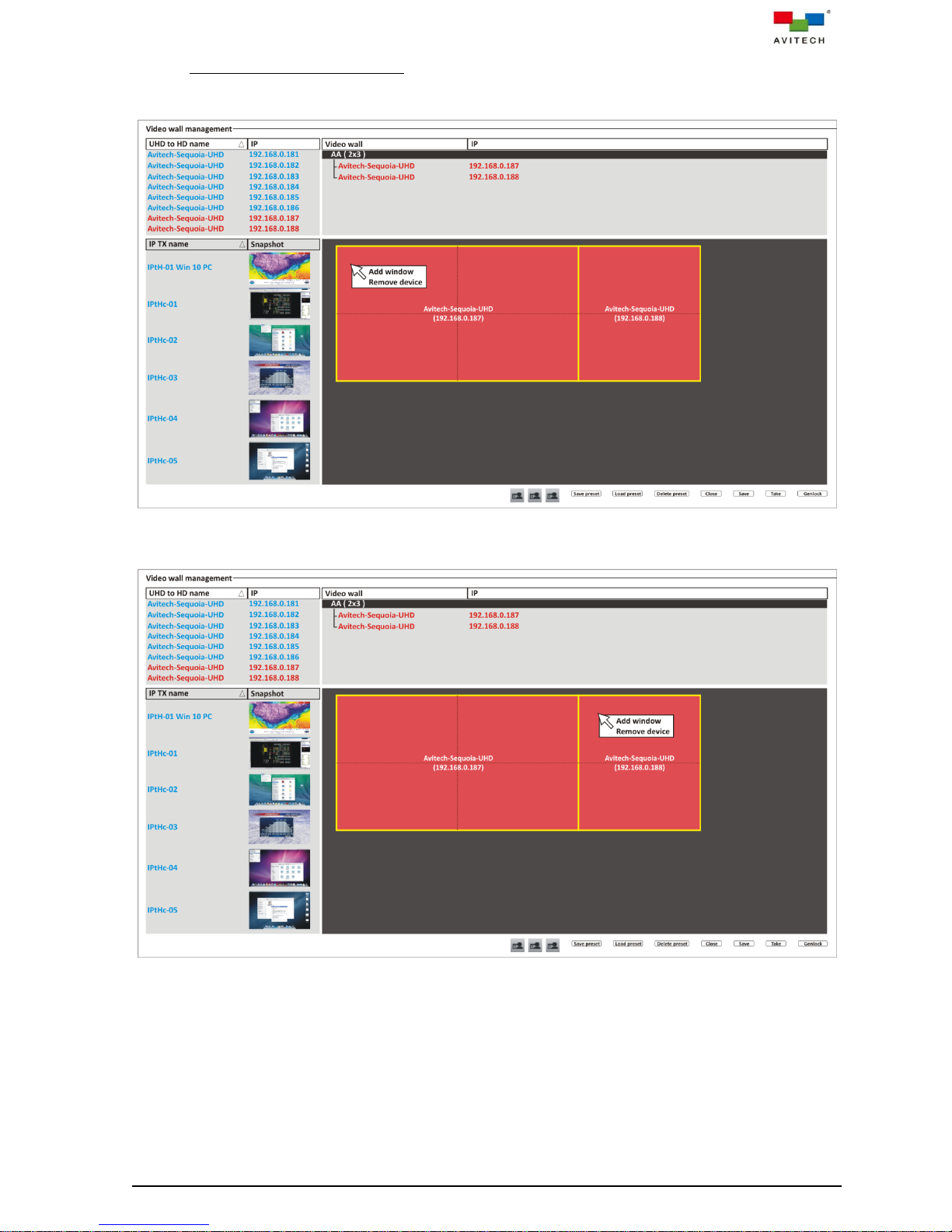
For 2×3 (and 3×4) Wall Display
On the 2×2 wall template, right-click anywhere and then click Add window.
Perform the same step to Add window on the 2×1 (and 1×2) wall template.
Figure 5-17 Add Window to the 2×2 Wall Template
Figure 5-18 Add Window to the 2×1 Wall Template
79
Page 87
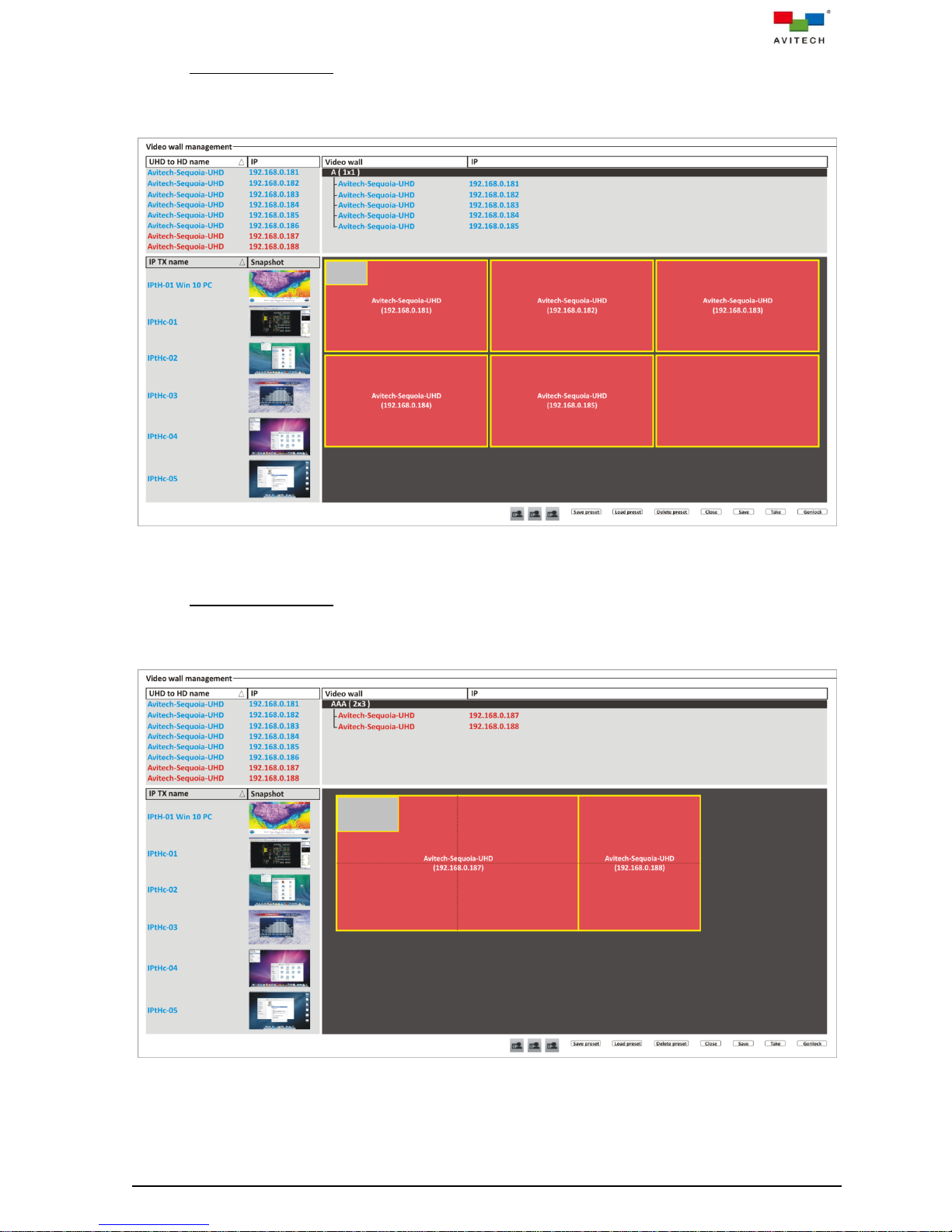
For 1×1 Wall Display
Notice that a window outline appears on the upper left corner of a display of 1×1 wall template.
Likewise, a window outline will appear on the upper left corner of the other four displays of 1×1
wall template upon adding a window to it.
Figure 5-19 Window Outline Appears Upon Adding a New Window to the 1×1 Wall Template
For 2×3 Wall Display
Notice that a window outline appears on the upper left corner of the 2×2 wall template. Likewise,
a window outline will appear on the upper left corner of the 2×1 wall template upon adding a
window to it.
Figure 5-20 Window Outline Appears Upon Adding a New Window to the 2×2 Wall Template
80
Page 88
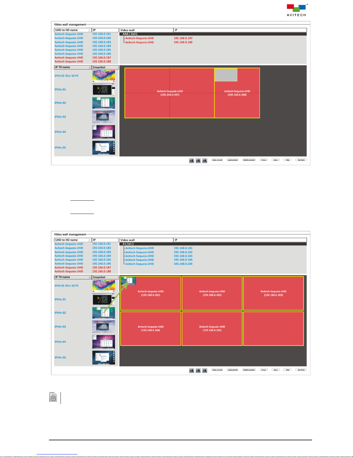
Figure 5-21 Window Outline Appears Upon Adding a New Window to the 2×1 Wall Template
Dragging another TX snapshot to a window that has a previously assigned TX source will replace the former
source.
Step 7. Two methods are available when assigning TX source to a window:
Method 1. Drag the TX snapshot or IP TX name to the blank window. Notice that the window
now displays the corresponding TX source image.
Method 2. Click to highlight (select) a TX source. Right-click anywhere on the wall template and
then click Add window. Notice that the new window already contains the corresponding TX
source image.
Figure 5-22 Drag the TX Snapshot to the Blank Window in the 1×1 Wall Template
81
Page 89
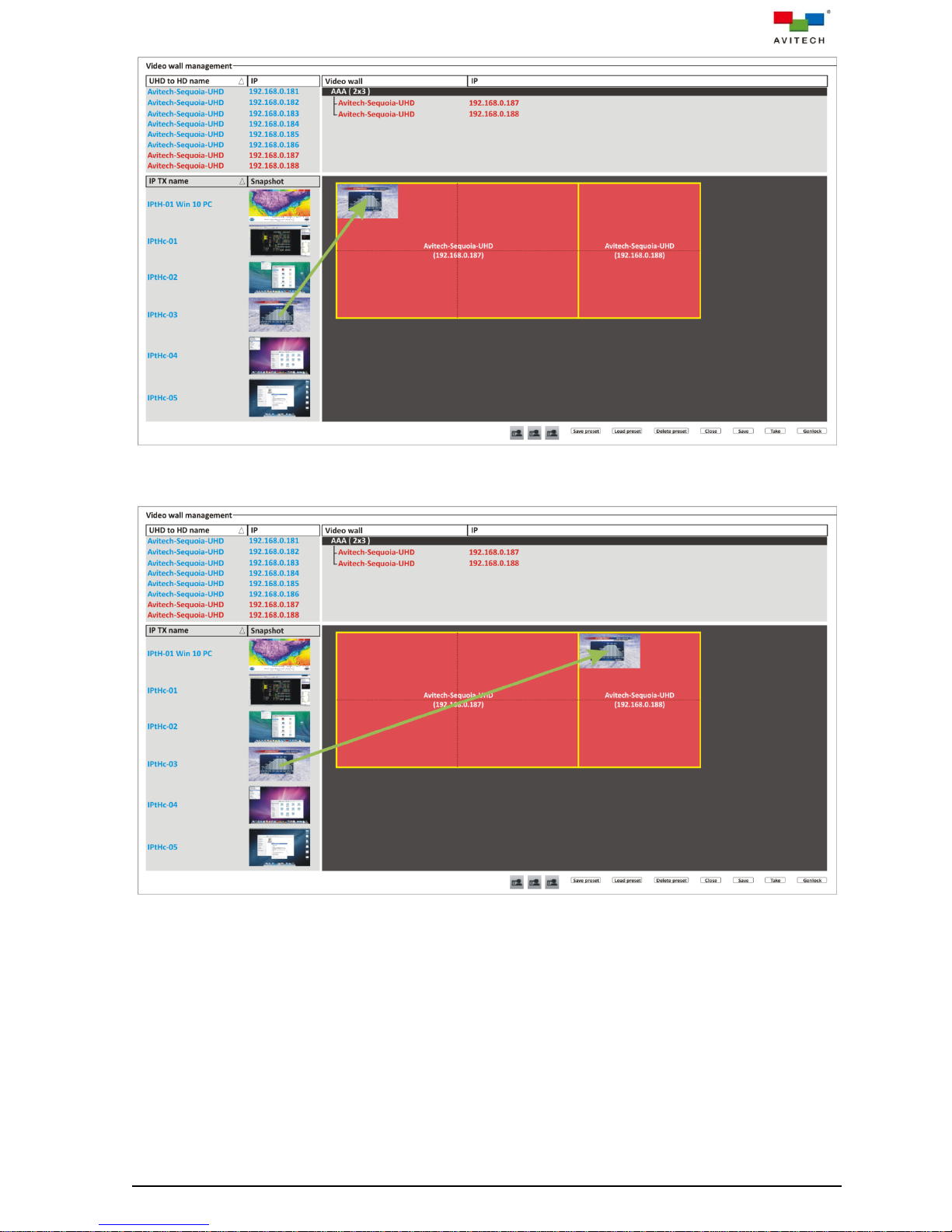
Figure 5-23 Drag the TX Snapshot to the Blank Window in the 2×2 Wall Template
Figure 5-24 Drag the TX Snapshot to the Blank Window in the 2×1 Wall Template
82
Page 90

Step 8. Before adding another new window, move aside (drag-and-drop) the first window so as not to
cause the new window to cover-up the first window. Every new window will originate on the
upper left corner of each wall.
Figure 5-25 Adding a Second Window to the 1×1 Wall Template
Figure 5-26 Adding a Second Window to the 2×2 Wall Template
83
Page 91

Figure 5-27 Adding a Second Window to the 2×1 Wall Template
1. Adding a fifth window to a display of the 1×1 wall is not allowed.
2. A window that straddles both 2×2 and 2×1 walls (as well as a window that straddles both 2×2 and 1×2
walls) will be counted as one window for each wall.
3. Adding a fifth window on either 2×2 and 2×1 walls and upon clicking the Take button may cause any of the
following to occur:
a. To cause the first window created to be hidden from view, or
b. To cause the first window that your mouse cursor has clicked out of the other three windows (not
necessarily the first window created) to become hidden from view.
But upon removing the newly added window and clicking the Take button, system will cause the hidden
window to reappear on the same position/size prior to its being hidden.
Continue to add / move (by clicking a window and without letting go of the mouse button to drag
it to its new location before letting go) / change window size (by clicking and dragging on any of
the four sides of a window) in this area.
Each display in the 1×1 wall can contain a maximum of four windows for a total of 24 windows.
The 2×2 wall can contain a maximum of four windows and the 2×1 wall can also contain a
maximum of four windows for a total of eight windows in the combined 2×3 wall.
Each of the two 2×2 wall can contain a maximum of four windows and each of the two 1×2 wall
can also contain a maximum of four windows for a total of 16 windows in the combined 3×4 wall.
84
Page 92

Figure 5-28 Right-click Menu for a Window in a Wall Display
1. Keep aspect ratio > All off, and upon adding a new window, the new window’s default setting will still be
On.
2. Keep aspect ratio > On, when dragging the window’s side to change its size and after lifting the left mouse
button, please wait awhile for system to recalculate the aspect ratio of the window based on its width.
3. Double-clicking a window (window must not straddle two monitors) will cause it to become full screen mode
(1080p) on the monitor that it currently occupies. If the window has Keep aspect ratio > On setting prior to
becoming full screen mode, system will automatically change its setting to become Off.
4. Double-clicking a window that straddles two monitors will not have any effect.
Upon right-clicking a window in the wall display, the following commands are available:
√ Remove window – removes a selected window from the wall.
√ Remove all windows – removes all windows from the wall display.
√ Full screen – transforms the selected window to full screen view (occupies the whole wall or
a whole display in the 1×1 wall).
√ Lock – toggles between locking/unlocking a selected window’s position and size (with/without
checkmark).
√ Keep aspect ratio – confines a/all window(s) to a fixed width-to-height ratio; a resized
window will also follow this aspect ratio. By default, the aspect ratio of a window is set to
match that of its corresponding video source. On – default.
√ Fine tune window position and size – upon clicking this, the following window appears:
Figure 5-29 Fine Tune Window Position and Size
85
Page 93

1. The smallest window size for any video wall configuration = 960×540. This means that if you are to set the
Width of a window to be lower than 960 then system will automatically change it to 960. Likewise, if you
are to set the Height of a window to be lower than 540 then system will automatically change it to 540.
2. Any adjustment for Width and Height would take priority over the values you could set for Horizontal
position and Vertical position. For example, if you are to set the Width as 1920 and the Horizontal
position as 1920 in a video wall display that has a maximum horizontal resolution of 3840, then it is within
the allowed valued because 1920 + 1920 = 3840. But if you are to set the Width as 1920 and Horizontal
position as 1921, then system will auto-correct your Horizontal position to be 1920 upon clicking the
Apply button.
3. Freely re-position the Fine tune window position and size window so that upon clicking Apply the effects
of your adjustment can be seen immediately. Click OK only when you are satisfied with your adjustment
and leave this window.
Horizontal position – allows you to set the window’s starting horizontal position (0 ~ x)
For a 1×1 video wall the maximum value (x) = 3840 – 960 = 2880.
The 1×1 video wall has a set width of 3840 pixels.
For a 2×2 video wall the maximum value (x) = 3840 – 960 = 2880.
The value 3840 is derived from 1920 × 2.
For a 2×3 video wall the maximum value (x) = 5760 – 960 = 4800.
The value 5760 is derived from 1920 × 3.
For a 2×4 / 3×4 video wall the maximum value (x) = 7680 – 960 = 6720.
The value 7680 is derived from 1920 × 4.
For a 1×2 UHD / 2×2 UHD video wall the maximum value (x) = 7680 – 960 = 6720.
The value 7680 is derived from 3840 × 2.
For a 1×3 UHD / 2×3 UHD video wall the maximum value (x) = 11520 – 960 = 10560.
The value 11520 is derived from 3840 × 3.
For a 2×1 UHD video wall the maximum value (x) = 3840 – 960 = 2880.
The 2×1 UHD video wall has a set width of 3840 pixels.
Vertical position – allows you to set the window’s starting vertical position (0 ~ y)
For a 1×1 video wall the maximum value (y) = 2160 – 540 = 1620.
The 1×1 video wall has a set height of 2160 pixels.
For a 2×2 / 2×3 / 2×4 video wall the maximum value (y) = 2160 – 540 = 1620.
The value 2160 is derived from 1080 × 2.
For a 3×4 video wall the maximum value (y) = 3240 – 540 = 2700.
The value 3240 is derived from 1080 × 3.
For a 1×2 UHD / 1×3 UHD video wall the maximum value (y) = 2160 – 540 = 1620.
The 1×2 UHD / 1×3 UHD video wall has a set height of 2160.
For a 2×1 UHD / 2×2 UHD / 2×3 UHD video wall the maximum value (y) = 4320 – 540 = 3780.
The value 4320 is derived from 2160 × 2.
86
Page 94

Figure 5-30 Right-click Menu for a Video Wall Name (Except 1×1 Video Wall)
Upon right-clicking a video wall name, the following commands are available:
√ Rename – rename a selected video wall.
√ Delete – remove a video wall.
√ Show all device editors – show all wall displays in a 1×1 video wall that may have been
closed.
√ Bezel gap adjustment – the following window appears. This item is not available for 1×1 wall
display but instead the abovementioned item Show all device editors will appear instead.
Figure 5-31 Bezel Gap Window
87
Page 95

The Bezel gap window allows you to adjust the pixel (offset) needed to align the image
1. Make sure to use an identical model and size of monitors when outputting a signal source
simultaneously to any wall display configuration.
2. Make sure to input at 4096×2160 resolution and output at 1920×1080 resolution.
3. This setting need be performed only once unless the monitors have been replaced.
seamlessly; more specifically the middle horizontal and vertical bezels of the wall display so
that your image/video spread on the monitors will appear more natural. The next two
illustrations show a sample 2×2 wall display before and after bezel gap adjustment.
Figure 5-32 Sample 2×2 Wall Display Before and After Bezel Gap Adjustment
Does the image appear to your satisfaction? If not, use the slider or input the number (0~300
pixel) to tweak your adjustment.
88
Page 96
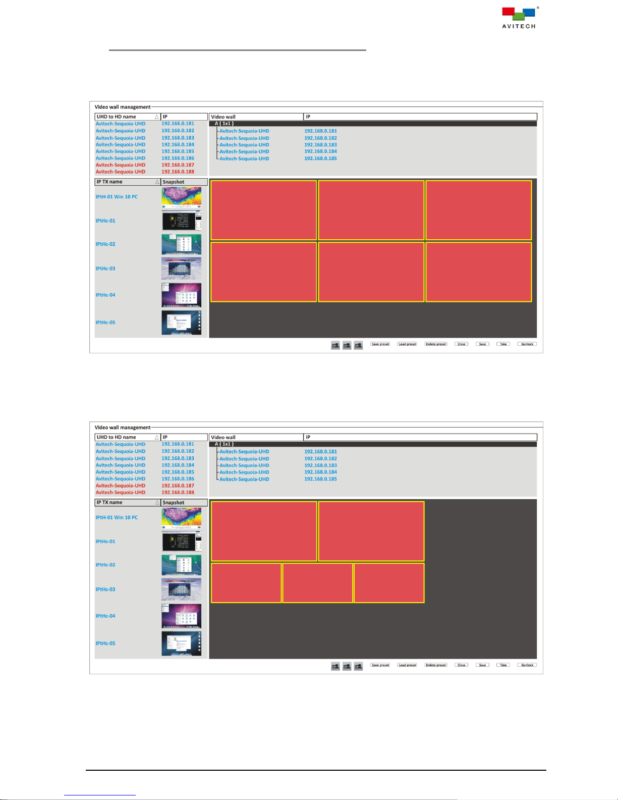
5.2 Additional Adjustments For 1×1 Wall Display
After adding a 1×1 wall display the default three horizontal walls by two vertical walls will appear. The
system then allows you to rearrange the position of the six walls as well as remove any of the walls.
Figure 5-33 Default 1×1 Wall Configuration
For example we wish to rearrange the video wall layout to become like below (two large walls on top of
three smaller walls). How should we go about it?
Figure 5-34 Designing a new 1×1 Wall Configuration
89
Page 97
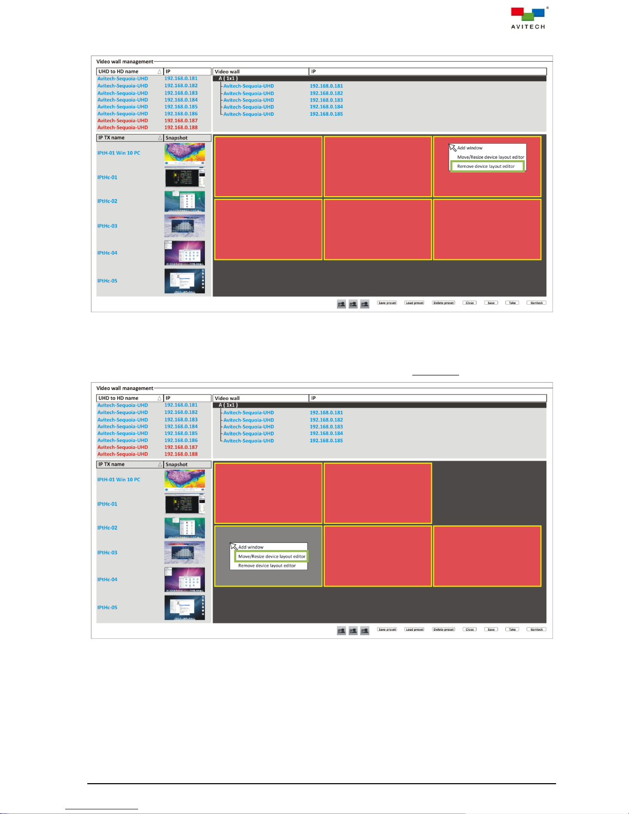
Step 1. Pick a wall to remove by right-clicking it and clicking the last item Remove device layout editor.
Figure 5-35 Remove a Wall
Step 2. Right-click the lower left wall and click the item Move/Resize device layout editor. Notice that
the wall turns into a gray background signifying that it is now in layout edit mode.
Figure 5-36 Wall in Layout Edit Mode
90
Page 98
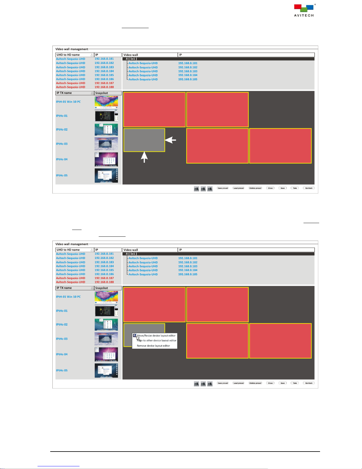
Step 3. While the wall is in layout edit mode, use the mouse to drag on the side(s) of the wall to enlarge
or shrink it (aspect ratio will always be maintained when dragging on any of the sides). You can
also reposition by clicking and dragging anywhere within the wall.
Figure 5-37 Resize the Lower Left Wall
Step 4. Right-click the wall and click Move/Resize device layout editor (with checkmark) to exit layout
edit mode for this wall. The wall will revert back to its original reddish background to signify that
it is not in layout edit mode anymore.
Figure 5-38 Exit the Layout Edit Mode
91
Page 99
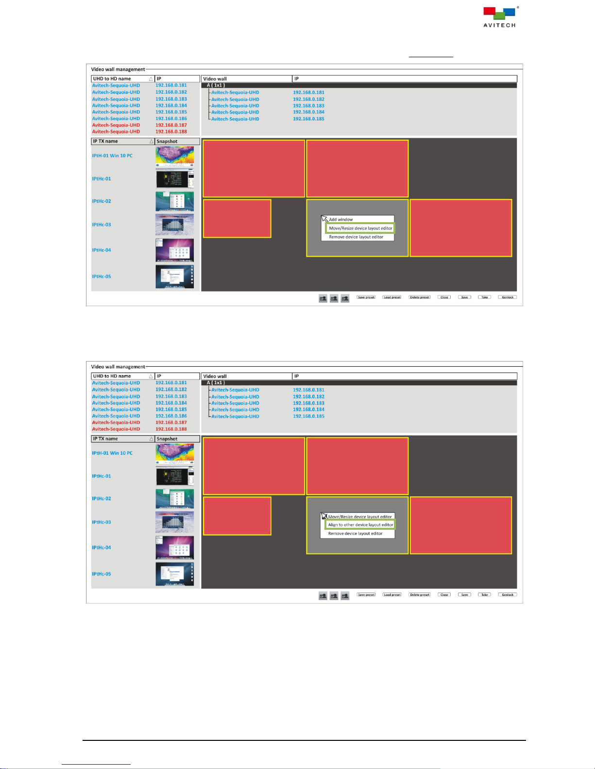
Step 5. Right-click the lower middle wall and click the item Move/Resize device layout editor. Notice
that the wall turns into a gray background signifying that it is now in layout edit mode.
Figure 5-39 Wall in Layout Edit Mode
Step 6. Again, right-click the wall and click Align to other device layout editor.
Figure 5-40 Click “Align to Other Device Layout Editor”
92
Page 100
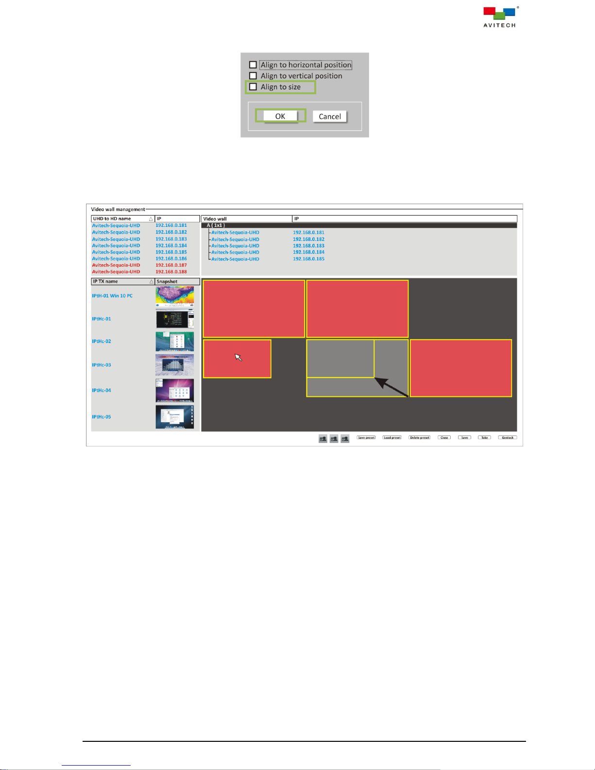
Step 7. When the following window appears click Align to size to select it. Then click OK.
Figure 5-41 Click “Align to Size”
Step 8. Click the wall that you wish to follow its size (left wall). Notice that the wall will shrink to be the
same size as the wall you copied from.
Figure 5-42 Wall Copy the Size
Step 9. Perform steps 5 ~ 8 for the lower rightmost wall.
93
 Loading...