

Page 1
User Manual
i
Rainier Summit
4K-Compatible Multiviewer with Integrated Router
Revision 1.0.0, (August, 2017)
Page 2

User Manual
ii
ABOUT THIS MANUAL
This manual contains information on how to use Avitech Rainier Summit series.
The following conventions are used to emphasize elements of text throughout the manual.
provides additional hints or information that require special attention.
identifies warnings which must be strictly followed.
Any name of a menu, command, icon or button displayed on the screen is shown in a bold typeset. For example: On
the Start menu select Settings.
To assist us in making improvements to this user manual, we welcome any comments and constructive criticism.
Email us at: sales@avitechvideo.com.
WARNING
Do not attempt to disassemble Rainier Summit series. Doing so may void the warranty. There are no user
serviceable parts inside. Please refer all servicing to qualified personnel.
TRADEMARKS
All brand and product names are trademarks or registered trademarks of their respective owners.
COPYRIGHT
The information in this manual is subject to change without prior notice. No part of this document may be
reproduced or transmitted in any form or by any means, electronic or mechanical, for any purpose, without the
express written permission of Avitech International Corporation. Avitech International Corporation may have
patents, patent applications, trademarks, copyrights or other intellectual property rights covering the subject matter
in this document. Except as expressly agreed in writing by Avitech International Corporation, the furnishing of this
document does not grant any license to patents, trademarks, copyrights or other intellectual property rights of
Avitech International Corporation or any of its affiliates.
TECHNICAL SUPPORT
For any questions regarding the information provided in this manual, please call our technical support help line at
425-885-3863, or our toll free help line at 1-877-AVI-TECH, or email us at: support@avitechvideo.com
Page 3

iii
Contents
About This Manual .................... ...................... ...................... ...................... ....................... ....... ii
Technical Support ..................................................................................................................... ii
Warranty .............. ...................... ...................... ...................... ...................... ....................... .......vi
Limitation of Liability ........................ ............................... .............................. ...........................vi
Extended Warranty Options .....................................................................................................vi
Services and Repairs Outside the Warranty Period ............... ......................... ........................vi
Regulatory Information .................. ............ ........... ........... ........... ........... ........... ........... ........... ..vi
Federal Communications Commission (FCC) Statement .......................................................vi
European Union CE Marking and Compliance Notices ................ .............. ............. .............. ..vi
Australia and New Zealand C-Tick Marking and Compliance Notice .....................................vi
1. Getting Started ............... ....................................... .................................... ..................... 1
1.1 Package Contents ... ................... .................... ................... .................... ................... .......... 1
1.2 Product Features ............................................................................................................... 2
1.3 Specifications .................................................................................................................... 4
1.4 Connections to the Rainier Summit ......................... ................................. ........................ 5
1.5 Connections to Redundant Power of Pacific Power Supply Station (PSS) ................... .. 6
1.6 Redundant Power Connection for Rainier Summit / Pacific PSS .................................... 7
2. Hardware Configuration ................................................................................................ 8
2.1 Installing the New Card on a Blank Slot ........................................................................... 8
2.2 Removing a Previously Installed Card ....................... .................... ................... ................ 9
3. Phoenix-Q Configuration ......................... ............. ............. ............. ............. ............. ... 11
3.1 Connection Method.......................................................................................................... 11
3.2 Pinging the Rainier Summit ............................................................................................. 11
3.3 Starting Up the Phoenix-Q Software ............................................................................... 12
3.4 Window Layout ................................................................................................................ 17
3.4.1 Arrange Windows (by Group) ........ ........... ........... ........... ............ ........... ........... ..... 17
3.4.2 Resize/Reposition Window . .............. .............. .............. .............. ............. .............. 19
3.4.3 Full Screen Mode; Swap Window Contents ................... ......... ........ ........ ......... ..... 20
3.4.4 Copy Window Properties ............ .................... ................... .................... ................ 20
3.4.5 Undo/Redo Changes .............................. .............. .............. .............. .............. ........ 22
3.4.6 Align Windows ............ .............................. ............................... .............................. 22
3.4.7 Copy Window Size .............. ................................. .................................. ................ 23
3.4.8 Remove Horizontal/Vertical Spacing .................................................................... 23
3.5 Temperature ............ ...................... ...................... ...................... ....................... ................ 24
3.6 Visual Studio ........ ............................ ........................... ............................ ......................... 24
3.7 Available Windows .......................................................................................................... 27
3.8 Log Window ..................................................................................................................... 29
Page 4

iv
3.9 Briefing ......................... .................... ................... .................... ................... ................... ... 30
3.10 Router ............. .............. .............. .............. .............. .............. .............. .............. .............. .. 31
4. Basic Setup Using the Phoenix-Q Software ..................... ................ ................. ......... 35
4.1 File Menu ........ ............................ ............................ ............................ ........................... ... 35
4.2 Edit Menu ......................................................................................................................... 37
4.3 View Menu .................. ........................... ............................ ............................ ................... 38
4.4 System Menu .................................................................................................................... 40
Import and Export Labels/Alarm Sound ......................................................................... 45
4.5 Help Menu ........................................................................................................................ 60
4.5.1 Firmware Version ........................... ................. ................ ................. ................. ..... 61
4.5.2 Upgrade Firmware ................................................................................................. 61
4.5.3 Product License .......................... ......................... ......................... ......................... 62
4.5.4 Alarm Log ......... ............. .............. .............. .............. .............. .............. .............. ..... 64
4.5.5 About ................ ...................... ...................... ...................... ...................... .............. 68
5. Setting the Chassis/Group/Card Properties .................. ................ ................ ............. 69
5.1 Rainier Summit Properties Setup ............... .............. .............. .............. ............. .............. 70
5.2 Setting Group Parameters ............................. ......................... ......................... .............. 103
6. Cascading ................ ................. ................ ................ ................. ................ ................ . 104
6.1 Internal Cascading ........................ ...................... ...................... ....................... .............. 104
6.1.1 Cascade of Three Groups and Duplicate Display ............................................... 104
6.1.2 Cascade Five Cards and One Independent Quad Display ................................. 106
6.1.3 Cascade All Six Cards ......................................................................................... 107
6.2 Internal Cascade with Built-in Router for Source / Multiview Output Configuration .. 108
6.3 Internal Cascading for Display Redundancy ................................................................ 113
6.4 External Cascading ......... ........... ........... ........... ............ ........... ........... ........... ........... ...... 116
6.4.1 Cascade Two Units via SDI Cascade In .............................................................. 116
6.4.2 Cascade 25 Cards via SDI Cascade In ................................................................ 116
Example: Take SDI output of any card to next chassis’ cascade input ............ 117
6.4.3 Cascade Three Units via SDI Cascade Plus Genlock Source Cascade In ......... 121
Appendix A Setting Up the Alarm Sound ..................................................................... 123
A.1 Alarm Sound Setup for No Video / Video Black / Video Freeze Occurrence .............. . 123
A.2 Alarm Sound Setup for No Audio Occurrence ............................................................. 125
A.3 Import and Export Alarm Sound ................................................................................... 127
A.4 Special Layout ............................................................................................................... 129
Appendix B Setting Up Audio................................... ................ ................. ................ .... 130
B.1 Setting Up the Speaker ID / Headphone for Audio Monitoring .................................... 130
B.2 Setting Up the SDI Output With Audio ............ ............................... ............................... 132
B.3 Setting Up the HDMI Output With Audio ......... ......................... ......................... ............ 133
Sample Illustration 1 ................ .............................. ............................... ......................... 135
Page 5

v
Sample Illustration 2 ................ .............................. ............................... ......................... 137
Appendix C Setting Up Static IP ..................... ................ ................. ................ .............. 141
Method 1: Change the IP Address of the Rainier Summit Chassis ............ ............. ............ 141
Method 2: Change the IP Address of the Controlling Computer .......... ........ ......... ........ ...... 143
For Windows XP ............................................................................................................. 143
For Windows 7 ............................................................................................................... 143
Appendix D Resetting to the Factory-Default State ..................................................... 144
Method 1: Using the Dip Switch .................. ............................... .............................. ............ 144
Method 2: Using the Phoenix-Q Software .................... .............. .............. .............. .............. 144
Appendix E Compatibility with Third-party Interface Device ...................................... 146
Setting Up the Configuration ....... ........ ........ ......... ........ ........ ......... ........ ........ ......... ........ ...... 146
Appendix F Compatibility with the Sony Switcher Interface Device .......................... 150
F.1 Setting Up the Configuration ........ ........... ........... ........... ........... ........... ............ ........... ... 150
F.2 Connecting With a Sony Production Switcher via Serial Mode ....................... ............ 152
F.3 Connecting With a Sony Production Switcher via Parallel Mode ................................ 154
Appendix G Avitech Trial Product Licensing ............................................................... 156
G.1 Trial License Statement ..... ............................ ........................... ............................ ......... 156
G.1.1 License .................. ............................... .............................. ............................... ... 156
G.1.2 Terms ................................................................................................................... 156
G.2 Conversion from a Trial License to an Authorized License ............. ................... ......... 156
G.2.1 Exporting the Machine ID .................................................................................... 156
G.2.2 License Update .................................................................................................... 159
Page 6

vi
Warranty
Avitech International Corporation (herein after referred to as “Avitech”)
warrants to the original purchaser of the prod ucts manufactured in its
facility (the “Product”), that these products will be free from defects in
material and workmanship for a period of 1 year or 15 months from the
date of shipment of the Product to the purchas er. There is a 3 month
grace period between shipping and installation.
If the Product proves to be defective during the 1 year warranty period,
the purchaser’s exclusive remedy and Avitech’s sole obligation under
this warranty is expressly limited, at Avitech’s sole option, to:
(a) repairing the defective Product without charge for parts and labor;
or (b) providing a replacement in exchange for the defective Product;
or (c) if after a reasonable time is unable to correct the defect or
provide a replacement Product in good working order, then the
purchaser shall be entitled to recover damages subject to the limitation
of liability set forth below.
Limitation of Liability
Avitech’s liability under this warranty sha ll not exceed the purchase
price paid for the defective product. In no event shall Avitech be liable
for any inci dental, special, or consequential damages, including
without limitation, loss of profits for any breach of this warranty.
If Avitech replaces the defective Product with a replacement Product
as provided under the terms of this Warranty, in no event will the term
of the warrant y on the replacem ent Product exceed the number of
months remaining on the warranty covering the defective Product.
Equipment manufactured by other suppliers and supplied by Avitech
carries the respective manufacturer’s warranty. Avitech assumes no
warranty responsibility either expressed or implied for equipment
manufactured by others and supplied by Avitech.
This Warranty is in lieu of all other warranties expressed or implied,
including without limitation, any implied warranty of merchantability or
fitness for a particular purpose, all of which are expressly disclaimed.
This Hardware Warranty shall not apply to any defect, failure, or
damage: (a) caused by improper use of the Product or inadequate
maintenance and care of the Product; (b) resulting from attempts by
other than Avitech representatives to install, repair, or service the
Product; (c) caused by installation of the Product in a hostile operating
environment or connection of the Product to incompatible equipment;
or (d) caused by the modification of the Product or integration with
other products when the effect of such modification or integrati on
increases the time or difficulties of servicing the Product.
Any Product which fails under conditions other than those specifically
covered by the Hardware Warranty, will be repaired at the price of
parts and labor in effect at the time of repair. Such repairs are
warranted for a period of 90 days from date of reshipment to customer.
Extended Warranty Options
Avitech offers OPTIONAL Extended Warranty plans that provide
continuous coverage for the Product after the expiration of the
Warranty Period. Contact an Av itech sales representative for details
on the options that are available for the Avitech equipment.
Services and Repairs Outside the Warranty Period
Avitech makes its best offer to repair a product that is outside the
warranty period, provided the product has not reached its end of life
(EOL). The minimum char ge for such repair excluding shipping and
handling is $200 (US dollars).
AVITECH INTERNATIONAL CORPORATION
● 15377 NE 90th Street Redmond, WA 98052 USA
● TOLL FREE 1 877 AVITECH
● PHONE 1 425 885 3863
● FAX 1 425 885 4726
● info@avitechvideo.com
● http://www.avitechvideo.com
Regulatory Information
Marking labels located on the exterior of the device indicate the
regulations that the model complies with. Please check the marking
labels on the device and refer to the corresponding statements in this
chapter. Some notices apply to specific models only.
Federal Communications Commission (FCC) Statement
This equipment has been tested and found to comply with the limits for
a Class A digital device, pursuant to Part 15 of the FCC Rules. These
limits are designed to provide reasonable protection against harmful
interference when the equipment is operated in a commercial
environment. T his equipment generates, uses, and ca n radiate r adio
frequency energy and, if not installed and used in accordance with the
instruction manual, may cause harmful interference to radio
communications. Operation of this equipment in a residential area is
likely to cause harmful interference, in which case the user will be
required to correct the interference at his own expense. Proper ly
shielded and grounded cables and connectors must be used in order
to meet FCC emission limits. Avitech is not responsible for any radio or
television interference caused by using other than recommended
cables and connectors or by unauthorized changes or modifications to
this equipment. Unauthorized changes or modifications could void the
user's authorit y to operate the equipment. Operation is subject to the
following two conditions: (1) this device may not cause harmful
interference, and (2) this device must accept any interference
received, including interference that may cause undesired operation.
European Union CE Marking and Compliance Notices
Statements of Compliance
English
This product follows the provisions of the European Directive
1999/5/EC.
Dansk (Danish)
Dette produkt er i overensstemmelse med det europæiske direktiv
1999/5/EC.
Nederlands (Dutch)
Dit product is in navolging van de bepalingen v an Europees Directief
1999/5/EC.
Suomi (Finnish)
Tämä tuote noudattaa EU-direktiivin 1999/5/EC määräyksiä.
Français (French)
Ce produit est conforme aux exigences de la Directive Européenne
1999/5/EC.
Deutsch (German)
Dieses Produkt entspricht den Bestimmungen der Europäischen
Richtlinie 1999/5/EC.
Ελληνικά (Greek)
To προϊόν αυτό πληροί τις προβλέψεις της Ευρωπαϊκής Οδηγίας
1999/5/EC.
Íslenska (Icelandic)
Þessi vara stenst reglugerð Evrópska Efnahags Ba ndalagsins númer
1999/5/EC.
Italiano (Italian)
Questo prodotto è conforme alla Direttiva Europea 1999/5/EC.
Norsk (Norwegian)
Dette produktet er i henhold til bestemmelsene i det europeiske
direktivet 1999/5/EC.
Português (Portuguese)
Este produto cumpre com as normas da Diretiva Européia 1999/5/EC.
Español (Spanish)
Este producto cumple con las normas del Directivo Europeo
1999/5/EC.
Svenska (Swedish)
Denna produkt har tillverkats i enlighet med EG-direktiv 1999/5/EC.
Australia and New Zealand C-Tick Marking and
Compliance Notice
Statement of Compliance
This product complies with Australia and New Zealand's standards for
radio interference.
Page 7

1
1. Getting Started
The Rainier Summit series is Avitech’s newest addition of multiviewers designed to meet 4K
monitoring demands. The 2RU Rainier Summit with modular design accommodates up to 24 multiplerate SDI/CVBS video sources on six hot-swappable multiviewer cards. Each card features both HDMI
and SDI outputs that can be independently configured to meet various display and production
requirements. Rainier Summit offers high-resolution multiview video and on-screen graphics up to 4K30
Ultra HD (UHD) clarity while managing with complete layout flexibility.
Utilizing a high-speed built-in router, Rainier Summit enables flexible routing and unlimited signal
repetition across image windows of different multiviewer cards. Through internal and external
cascading, it allows user to combine multiple cards for multiview monitoring of up to 100 sources; ideal
for building fully dynamic multiviewing systems for video production and master control.
This chapter introduces the features and specifications as well as the external components of Rainier
Summit.
1.1 Package Contents
The following standard items are included in the shipping package:
Avitech Rainier Summit series Utility Disc (software and user manual)
460 Watts Power Supply (optional)
Standard Power Cord (USA customer only) for
Rainier Summit series
DVI to HDMI Adapter (optional) RJ-50 GPI Terminal Block
DC to DC Cable (optional –
when purchasing redundancy power)
D
Power Supply Station (optional –
when purchasing redundancy power)
Ear with screw (installed on Rainier Summit
Series upon order for assembly on to rack mount)
D
Table 1-1 Package Contents
Page 8

2
Due to space limitation the LTC 1, LTC 2 and serial connectors are replaced with a RJ-50 connector. The
pin definition of the RJ-50 terminal block is shown next.
Figure 1-1 Avitech RJ-50 Pin Definition
1.2 Product Features
Rainier Summit modular 2U chassis houses up to six Independent multiviewer cards and
ensures no single point of failure
Hot-swappable I/O card and fan module support field-serviceable card expansion and
reconfiguration without interrupting signal routing
Integrated router enables any-to-any signal routing and repetition across multiple windows/
displays; no external upstream router is required
Automatic sensing of SDI (3G-Level A & B /HD/SD) and CVBS (NTSC/PAL) input signals
Support of both HDMI and SDI multiviewer output; HDMI supports full range of resolutions up to
4K UHD (3840
×
2160/30Hz/4:2:2)
Multiview outputs can be duplicated and concurrently monitored from different cards without
external DA or routing cabling
Internal cascade allows grouping of any selected modules for displaying 8, 12, 16, 20, and 24
image/video sources on one screen, or duplicates the same image to respective outputs
Support of 16-channel SDI embedded audio and audio delay adjustment
Cascading up to 25 cards from multiple Rainier Summit facilitates the monitoring of 100 sources
on one display or duplicated to multiple displays
Seamless layout control and system configuration through dedicated control software; all
cascaded units are controlled and managed instantly via one software
Linear Time Code (LTC) – optional / Vertical Interval Time Code (VITC) – optional / Embedded
(LTC/VITC/DVITC) Time Code detect and display
Genlock capability supports synchronizing multiviewer outputs to the reference signal and the
rest of studio/production equipment
Supports Avitech’s Phoenix-Q configuration interface through an Ethernet connection
Supports TSL through Ethernet (IP) or serial interface (RS-232)
Supports General Purpose Input/Output through Ethernet (working in conjunction with Avitech’s
Pacific GPIO Box)
Supports Avitech HTTP Protocol
Page 9

3
Redundant hot-swappable power supply (working in conjunction with Avitech Pacific PSS
(Power Supply Station))
Video and Audio Control:
1. Free-scaling windows, quad view, Picture-in-Picture (PiP), full screen view, adjustable safe
area, and aspect ratio control
2. Image cropping and panning
3. Closed Caption (CC) detection
4. Supports 16-channel SDI embedded audio; 8 channels selectable for monitoring via OSD
5. Adjustable audio delay (0 ~ 2700ms)
6. Audio output supports up to 8-channel HDMI / 16-channel SDI embedded or stereo phone
jack audio output
On Screen Display (OSD):
1. Border
Image borders
Video borders
2. Labels
True type font label
UMD – (under monitor display)
3. Alarms
Video: Video loss / Video freeze / Video black
Audio: Audio loss / Audio high / Audio low / Out of Phase
Fan failure alarm
Power failure alarm
System operating temperature monitoring alarm
Timecode Loss (for SDI embedded timecode only)
4. Signal format / Active Format Description (AFD) / Closed Caption detection
5. Tally (up to four tallies per image window)
6. Audio meter
7. Loudness meter (optional)
8. Digital clock (up to two digital clocks) and Analog clock (up to two analog clocks) per card
9. User logo, display label and configurable background color
10. External Linear Time Code display (option)
11. SDI Embedded Time Code display per image window
12. Safe area and aspect ratio detection
Page 10

4
1.3 Specifications
Rainier Summit – SDI card
Input
SDI/CVBS
(BNC connector)
Automatic sensing, the following input signals are supported:
3G-SDI: SMPTE 424M-2006 level A and level B-DS (Dual Stream)
YCbCr 4:2:2 10-bit
1080p60, 1080p59.94, 1080p50
HD-SDI: SMPTE 292M
1080p30, 1080p29.97, 1080PsF29.97 (segmented frame), 1080p25, 1080PsF24,
1080PsF23.98, 1080i60, 1080i59.94, 1080i50, 1035i60, 1035i59.94, 720p60,
720p59.94, 720p50, 720p30, 720p29.97, 720p25
SD-SDI: SMPTE 259M
525_60, 625_50
CVBS: NTSC/PAL
Output
HDMI and DVI
(through HDMI to DVI
adapter)
Normal/VESA output timing; 8-bit/10-bit HDMI color depth;
User configurable:
3840×2160 (4K UHD) 25Hz/30Hz
1920×1200 (WUXGA) 50Hz/60Hz
1920×1080 (HD 1080) 50Hz/59.94Hz/60Hz Progressive
1920×1080 (HD 1080) 50Hz/59.94Hz/60Hz Interlaced
1280×720 (HD 720) 50Hz/59.94Hz/60Hz
640×480 (VGA) 60Hz
Note
: The 59.94Hz refresh rate is only supported during transmission of a genlock
source to the Ref IN port.
SDI
(BNC connector)
User configurable:
1920×1080 50Hz/60Hz Progressive (4:2:2 YCbCr/10-bit)
1920×1080 50Hz/60Hz Interlaced (4:2:2 YCbCr/10-bit)
Table 1-3 Rainier Summit – SDI Card Specifications
Rainier Summit – Control card
Control interface
(RJ45/RJ50 connector)
Serial: for connecting to TSL port of the TSL controller for TSL interface
Ethernet for connecting to Windows-based Phoenix-Q software
Cascade
(BNC/HDMI connector)
For cascaded SDI/HDMI input signals from an upstream Rainier Summit
LTC/VITC
(RJ50/BNC connector)
BNC connector: for the third Linear (or Longitudinal) Timecode input or Vertical
Interval Timecode input
RJ50 connector: for first and second LTC input
Electrical: single end
Impedance: >30k ohms
Sensitivity: 500 mV pk-pk (5V maximum)
Audio
(Headphone jack)
Analog audio (stereo audio output)
Keyboard/Mouse control
(USB A connector)
For in-system GUI’s keyboard/mouse control (not available in the first release)
For alarm log in the USB thumb drive
Power
Power consumption: 460 Watt (maximum)
Power Supply
For in system power supply: AC100~240V 50/60Hz
PIB (working in conjunction with Avitech Pacific PSS POB): 12 V DC
Dimension/Weight
Dimension: 15.72 × 17.28 × 3.50 inch (39.93 × 43.90 × 8.88 cm)
Weight: 18.74 lbs (8.50 Kg)
Page 11

5
Rainier Summit – Control card
Environment/Safety
Temperature:
Operating: 0
°
C (32 °F) to 40 °C (104 °F)
Storage: –10
°
C (14 °F) to 50 °C (122 °F)
Humidity, 0% to 80% relative, non-condensing
Safety, FCC/CE/C-Tick Class A
Table 1-4 Rainier Summit-2 – Control Card Specifications
1.4 Connections to the Rainier Summit
Figure 1-1 Rainier Summit Control Card Components
Control Card
Ethernet (IP)
Ethernet (IP) port for window layout control, preset save and recall, and system
configuration via Windows-based Phoenix-Q software.
Ref Out
For Genlock signal output that supports:
720p 50Hz, 720p 59.94Hz, 720p 60Hz
Ref In
For Genlock signal input that supports:
Black Burst, Tri-level and SD/HD/3G-SDI
LTC/VITC In
For external timecode input
Linear (or Longitudinal) timecode input (encoding of SMPTE timecode data in an
audio signal) (LTC 3)
Vertical interval timecode (encoding of SMPTE timecode data into the vertical
blanking interval of the video signal)
LTC/Serial
For external linear timecode inputs (LTC1 and LTC2) and TSL controller
communication via RS-232 interface
Cascade In 1/2
BNC connectors for externally cascaded SDI input signals from an upstream Rainier
Summit (cascade input 1 and cascade input 2)
HDMI In
For externally cascaded HDMI input signal from an upstream Rainier Summit
HDMI Out
For in-system GUI’s display
Keyboard/Mouse
For in-system GUI’s keyboard and mouse control (not available in the first release)
For alarm log in the USB thumb drive
ID
Rotary dial to assign unique addresses in systems with two or more cascaded
chassis.
Headset
1/8 inch audio port for connecting headphones (stereo)
Power AC100~240V 50/60Hz
Dip Switches
Updates the firmware; as well as resets the Rainier Summit to the factory-default
setting.
Note
: Dip Switch 2 is for factory reset, see Appendix D.
Table 1-6 Rainier Summit-2 Rear Component Description
Page 12

6
Figure 1-2 Rainier Summit Multiview Card Components
SDI Card
SDI/CVBS IN
BNC connectors for SDI (3G Level A and B /HD/SD) / CVBS (NTSC/PAL) video
source signals
Supports up to 16-channel embedded audio, with 8 channels selectable for
on-screen monitoring
HDMI OUT
HDMI connector for outputting the multiview signal to HDMI or DVI display (for
monitoring resolution up to 4K30 UHD)
Supports 8-channel embedded audio (for HDMI output)
SDI OUT
BNC connector for SDI output
Supports up to 16-channel embedded audio
Independently configured multiview video with resolution up to 1080p60
Routed output for any of the 24 source signals
Table 1-7 Rainier Summit-2 – (SDI Card) Component Description
1.5 Connections to Redundant Power of Pacific Power Supply Station (PSS)
Power Input Board (PIB) of Rainier Summit-2 for redundant power
Figure 1-3 Rainier Summit Multiview Power Input Board Components
Rainier Summit-2
DC INPUT (PIB) DC connector for 12V / 19A power input
Table 1-8 Power Input Board – Component Description
Page 13

7
Power Output Board (POB) of Pacific PSS for redundant power
Figure 1-4 Pacific PSS Components
Pacific PSS
Power IN
AC100~240V 50/60Hz
Ethernet (IP)
Ethernet (IP) port for control, power supply status monitoring and system
configuration via Windows-based Phoenix-Q software
DC OUT (POB)
DC connector for 12V / 17A power output
Table 1-9 Pacific PSS – Component Description
1.6 Redundant Power Connection for Rainier Summit / Pacific PSS
The following illustration shows a redundant power connection for the Rainier Summit and PSS (Power
Supply Station).
Figure 1-5 Redundant Power Connection
Step 1. Connect one end of the first DC to DC cable to the DC OUT port on the POB (Power Out Board)
of the Pacific PSS. Connect one end of the second DC to DC cable to the DC OUT port on the
POB of the Pacific PSS.
Step 2. Connect the other end of the first DC to DC cable to the DC IN port on the PIB (Power In Board)
of the Rainier Summit. Connect the other end of the second DC to DC cable to DC IN port on the
PIB of the Rainier Summit.
Step 3. Connect the AC power cords to the 100~240V power jack for both of the Power Supply.
Page 14

8
2. Hardware Configuration
This chapter discusses the process of installing a card into the Rainier Summit chassis.
1. To prevent any damage to hardware components as well as avoid any injury, make sure to turn off
power coming from the power strip to Rainier Summit before making any changes to the hardware
configuration.
2. Not applicable for Rainier Summit-S.
2.1 Installing a New Card on a Blank Slot
The Rainier Summit chassis accepts the following card:
Rainier Summit
–
(SDI card)
Step 1. Remove the two screws securing the back plate.
Figure 2-1 Remove the Two Back Plate Screws
Step 2. Remove the back plate.
Figure 2-2 Remove the Back Plate
Page 15

9
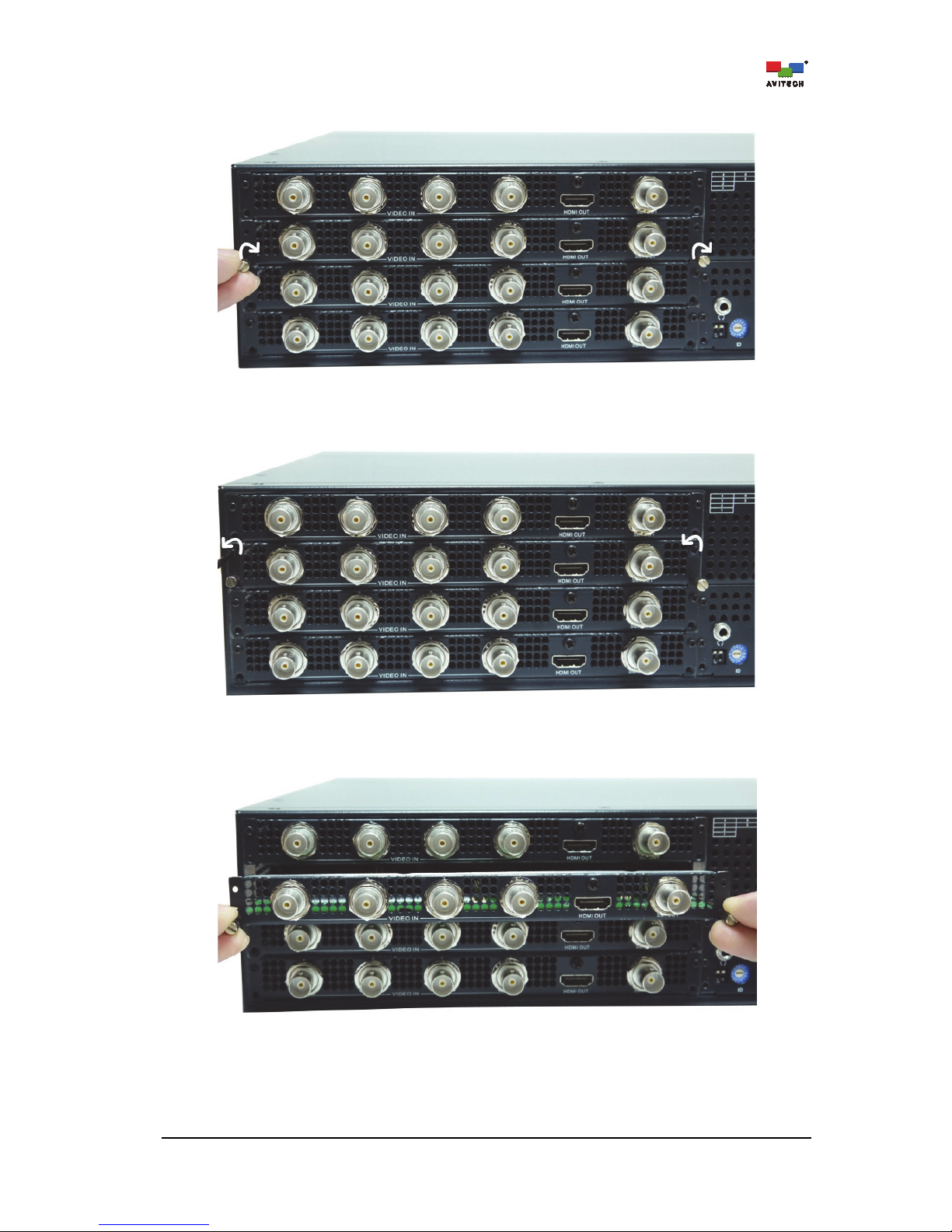
Step 3. Align both sides of the card to the rails, and slide all the way into the chassis.
Figure 2-3 Align the New Card to the Rail on Both Sides
Step 4. Tighten the screws on both sides to secure the new card to the chassis.
Figure 2-4 Tighten the Screws on Both Sides
2.2 Removing a Previously Installed Card
Step 1. Use a flat screwdriver to unscrew the left and right puller screws on the control card module.
Figure 2-5 Remove the Left and Right Puller Screws on Control Board
Page 16
10
Step 2. Use the just removed puller screws and screw it to both sides of the card to be removed.
Figure 2-6 Screw the Left and Right Puller Screws to Old Card
Step 3. Remove the left and right screws securing the card to be removed from the chassis.
Figure 2-7 Remove the Left and Right Screws
Step 4. Grasp both left and right puller screws and pull the card to be removed away from the chassis.
Figure 2-8 Pull the Left and Right Puller Screws
Step 5. Remove left and right puller screws on just removed card and return to control board module.
Page 17

11
3. Phoenix-Q Configuration
The Avitech Phoenix-Q program requires no installation. Just copy and run the system files on the
computer’s hard drive. This chapter introduces the Phoenix-Q software for setting up the Rainier
Summit.
1. Make sure the Rainier Summit is powered on and connected properly to the computer via Ethernet
before launching the Phoenix-Q software.
2. DO NOT
use the serial cable to connect the Rainier Summit to the computer. The serial port is for
connecting to a TSL controller/interface.
3.1 Connection Method
Connect the Rainier Summit to the controlling computer via an Ethernet cable.
Before connecting the computer to the Rainier Summit, the computer will need to be changed to a static
IP, and its subnet mask must be set to a similar range as the Rainier Summit (“192.168.0.5” – factorydefault IP address). Or, the IP address of the Rainier Summit can be changed to a similar range as the
controlling computer. See Appendix C for details.
3.2 Pinging the Rainier Summit
Make sure to be able to ping the chassis at “192.168.0.5” (factory-default IP address).
Step 1. Run the Phoenix-Q software by double-clicking Phoenix-Q.exe.
Step 2. Enter the factory-default IP address 192.168.0.5. Then click Ping.
Figure 3-1 Phoenix-Q Software: Enter the IP Address to Ping
Page 18

12
Step 3. The following window will appear to signify a successful communication. Click OK to exit.
Figure 3-2 Phoenix-Q Software: IP Address Pinged Successfully
3.3 Starting Up the Phoenix-Q Software
Step 1. Run the Phoenix-Q software by double-clicking Phoenix-Q.exe.
Step 2. Make sure to set the correct IP address (see Appendix C for details).
Step 3. Select the only type of connection allowed by clicking the IP Port checkbox. Then click
Connect.
Figure 3-3 Phoenix-Q Software: Select the Ethernet Connection Method
Page 19
13
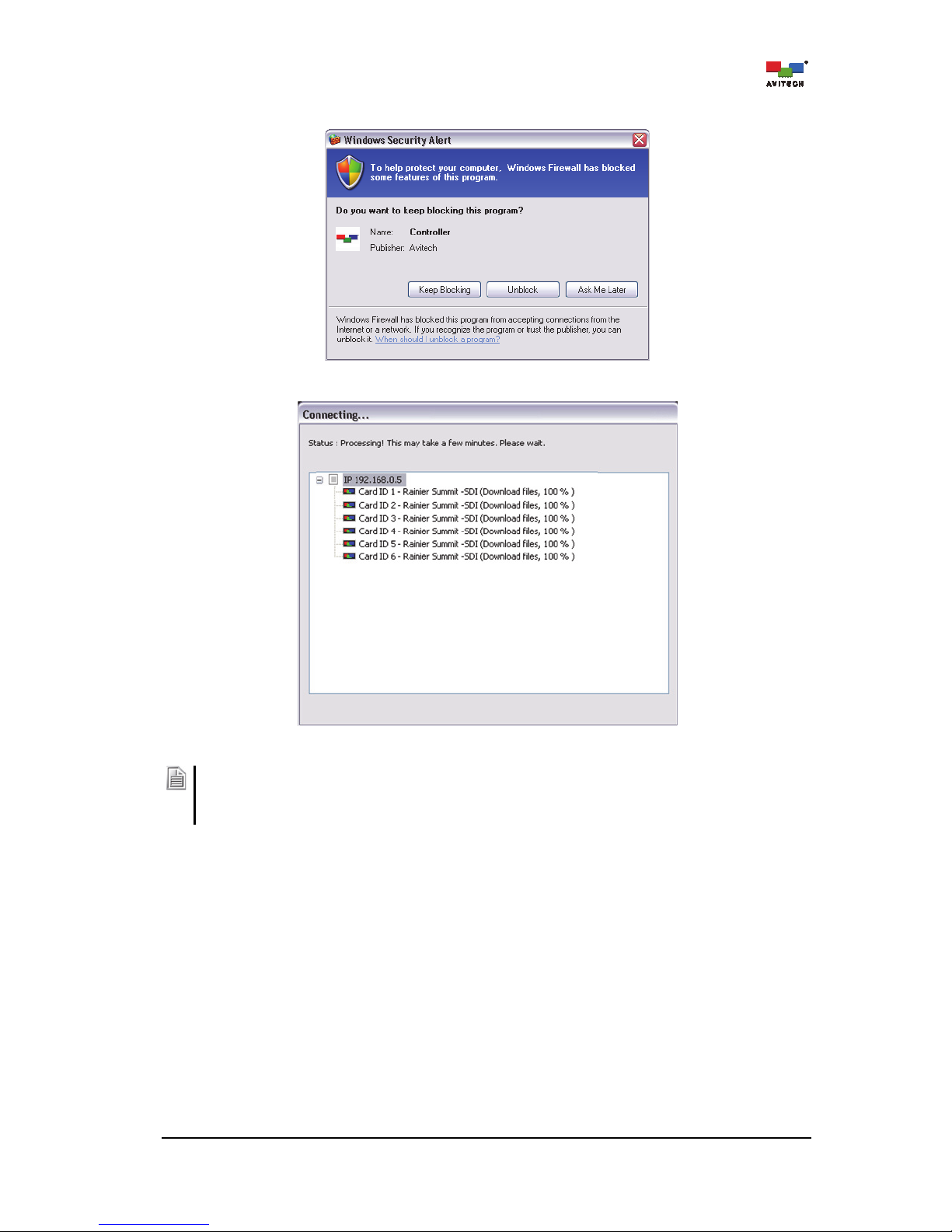
If Windows detects and pops up the security alert window as shown below, just click Unblock to proceed
.
Phoenix-Q will start to search for the Rainier Summit.
Figure 3-4 Phoenix-Q Software: Connection Progress
1. When cascading the Rainier Summit, make sure each chassis has been assigned a different IP
address.
2. Make sure the IP address of the computer running the Phoenix-Q software is in the same network as
that of the Rainier Summit.
Page 20
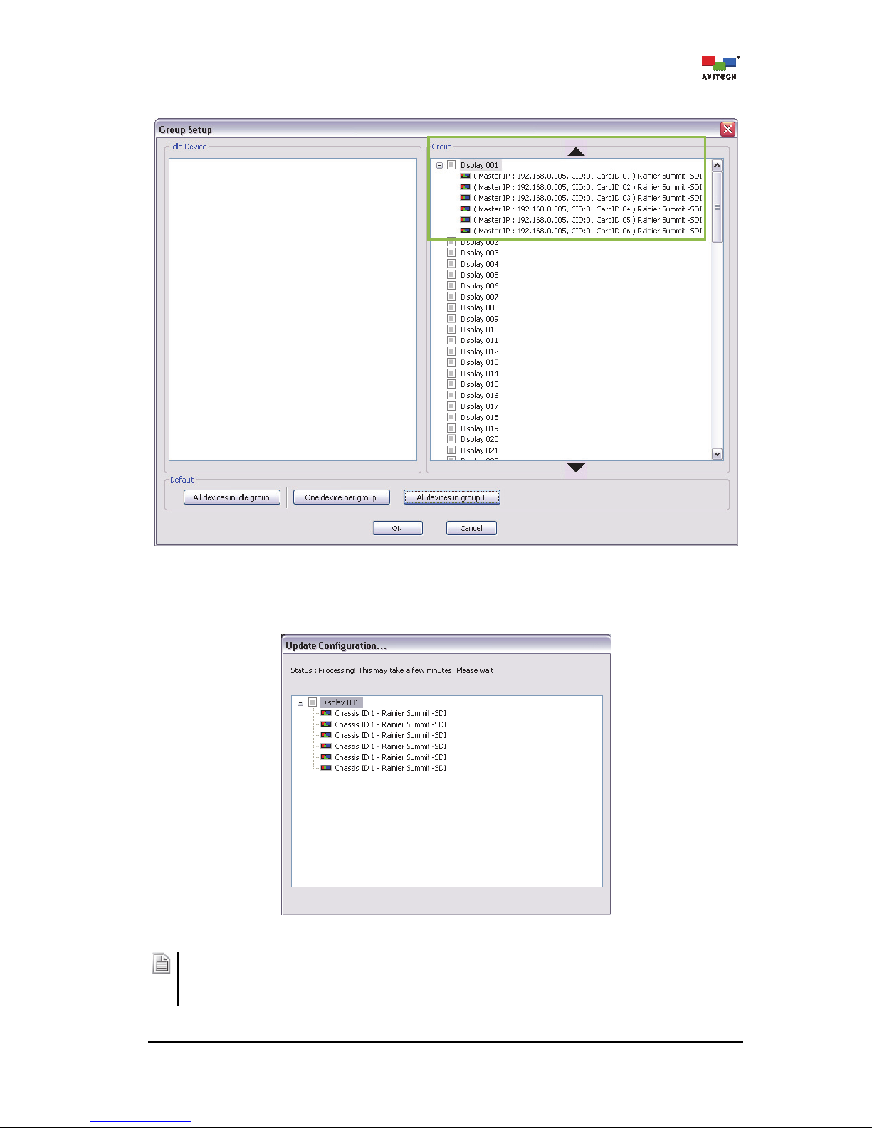
14
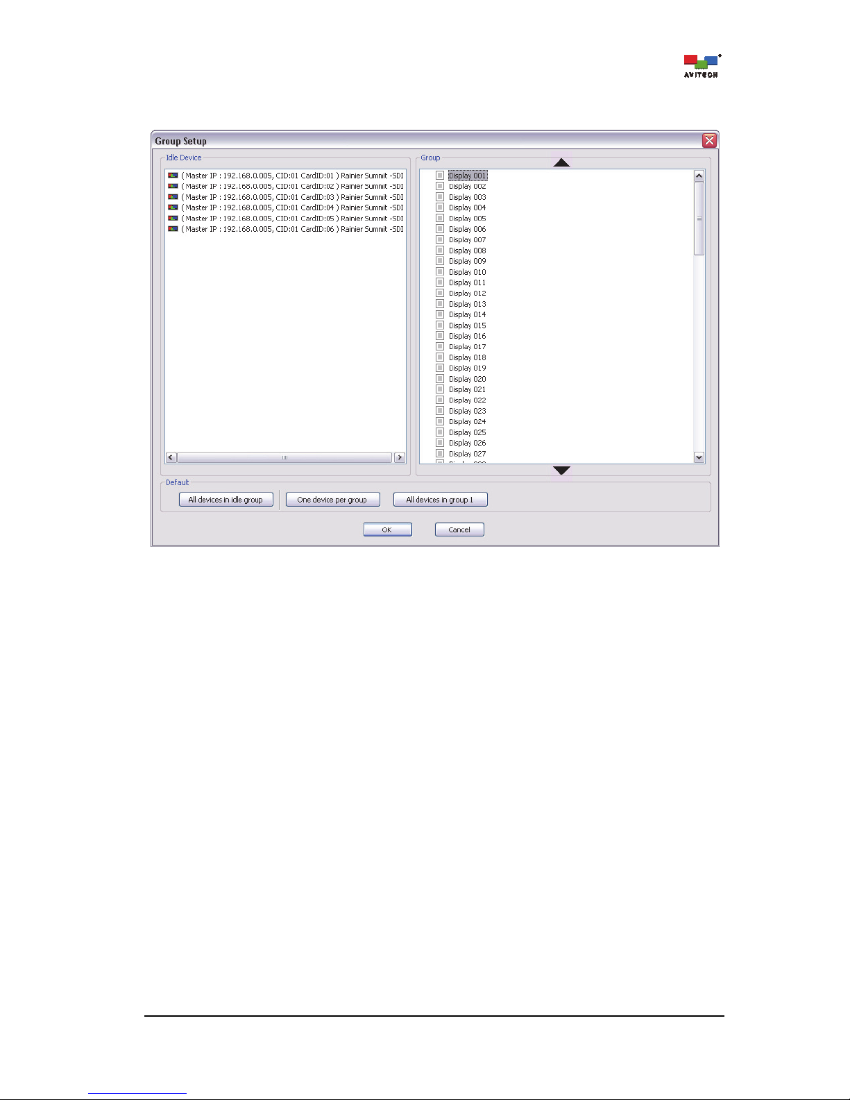
The Group Setup window will list all the card(s) of the Rainier Summit with the default IP under
Idle Device.
Figure 3-5 Phoenix-Q Software: Group Setup
Page 21

15
Step 4. To assign the grouping, drag an Idle Device listed on the left panel to the desired Group/
Display # on the right panel (i.e. Group/Display 001).
Figure 3-6 Phoenix-Q Software: Assign Idle Device to Group/Display #
Or, click the One Device Per Group button to assign a card of the Rainier Summit to each
display or click All Devices in Group 1 to assign all cards to belong to Group/Device 1.
Page 22
16
After being assigned, each card will be displayed under its respective assigned group/display.
Figure 3-7 Phoenix-Q Software: Idle Device Assigned to Group/Display 001
Step 5. Next, click OK to exit the Group Setup window. Phoenix-Q will save the configuration file
“System.json” to the device’s flash memory.
Figure 3-8 Phoenix-Q Software: Update the Configuration Progress
After completing the group/display setup, and any time afterwards when the IP address(s) of the Rainier
Summit is changed (see Appendix C), perform the simple step of entering the Group Setup window and
then clicking OK to exit (there is no need to re-assign the grouping as this has been done by the system).
This step is just to maintain system integrity when running the “HTTP” command.
Page 23
17
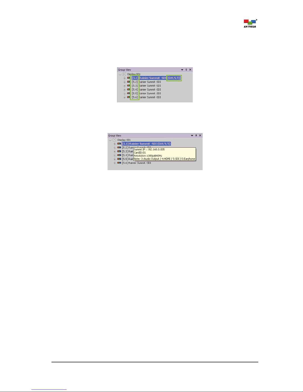
The next figure shows the sample devices assigned to “Group/Display 001.”
On the Phoenix-Q software interface shown below, “[5.1]” signifies the IP number of the chassis
and card ID number of the module assigned to the group/display. Hence “[5.2]” would signify a
chassis IP with number 192.168.0.5 and card ID number 2.
The “(O:H/S/E)” appearing after the Rainier Summit-SDI signifies audio “O”utput that is “H”DMI /
“S”DI / “E”arphone OUT.
Figure 3-9 Phoenix-Q Software: Chassis IP and Card ID Number; Audio Output Source Guide
Place the mouse cursor over a specific Rainier Summit and information regarding the “Summit
IP #” / “Card ID #” / “Resolution” / “Audio Output” for that device.
Figure 3-10 Phoenix-Q Software: Device Information and Reference
3.4 Window Layout
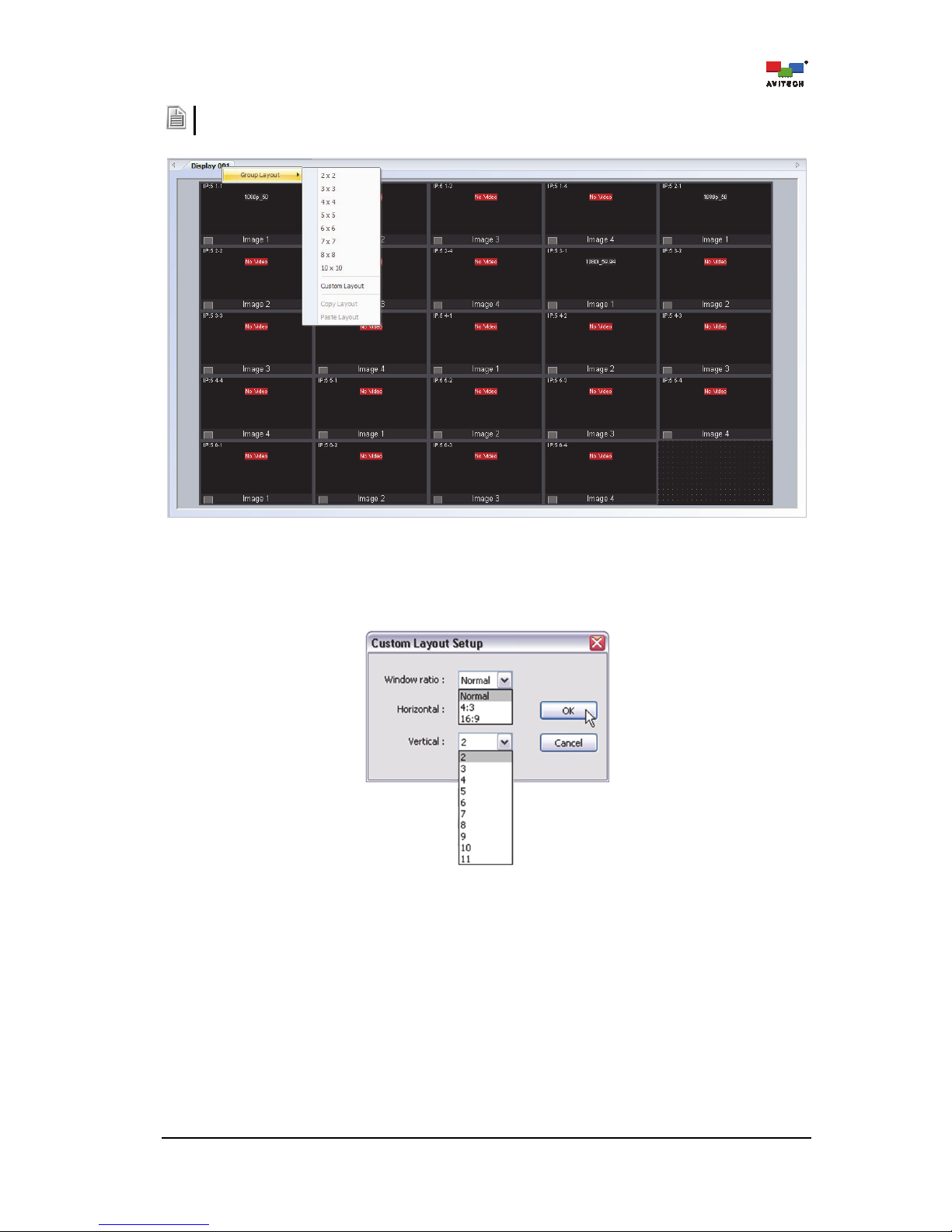
3.4.1 Arrange Windows (by Group)
For a quick layout setup of the video windows, right-click the “Group/Display ###” tab to access the
Group Layout menu. Select from 2×2 up to 10×10 as possible grid positions on the monitor.
Throughout this manual, we will refer to the multiple window interface shown below as the “main display
area”.
Page 24
18
The layout size available for the particular model will depend on the monitor’s supported resolution, OSD
display and the smallest window size limitation.
Figure 3-11 Phoenix-Q Software: Group Layout
Upon selecting Custom Layout, specify the Window Ratio (Normal / 4:3 / 16:9). If Normal is selected,
set the Horizontal and Vertical number of windows (2 to 11) as possible grid positions on the monitor. If
4:3 or 16:9 is selected, just set the Horizontal number of windows (2 to 11).
Figure 3-12 Phoenix-Q Software: Set Customized Layout
Page 25
19
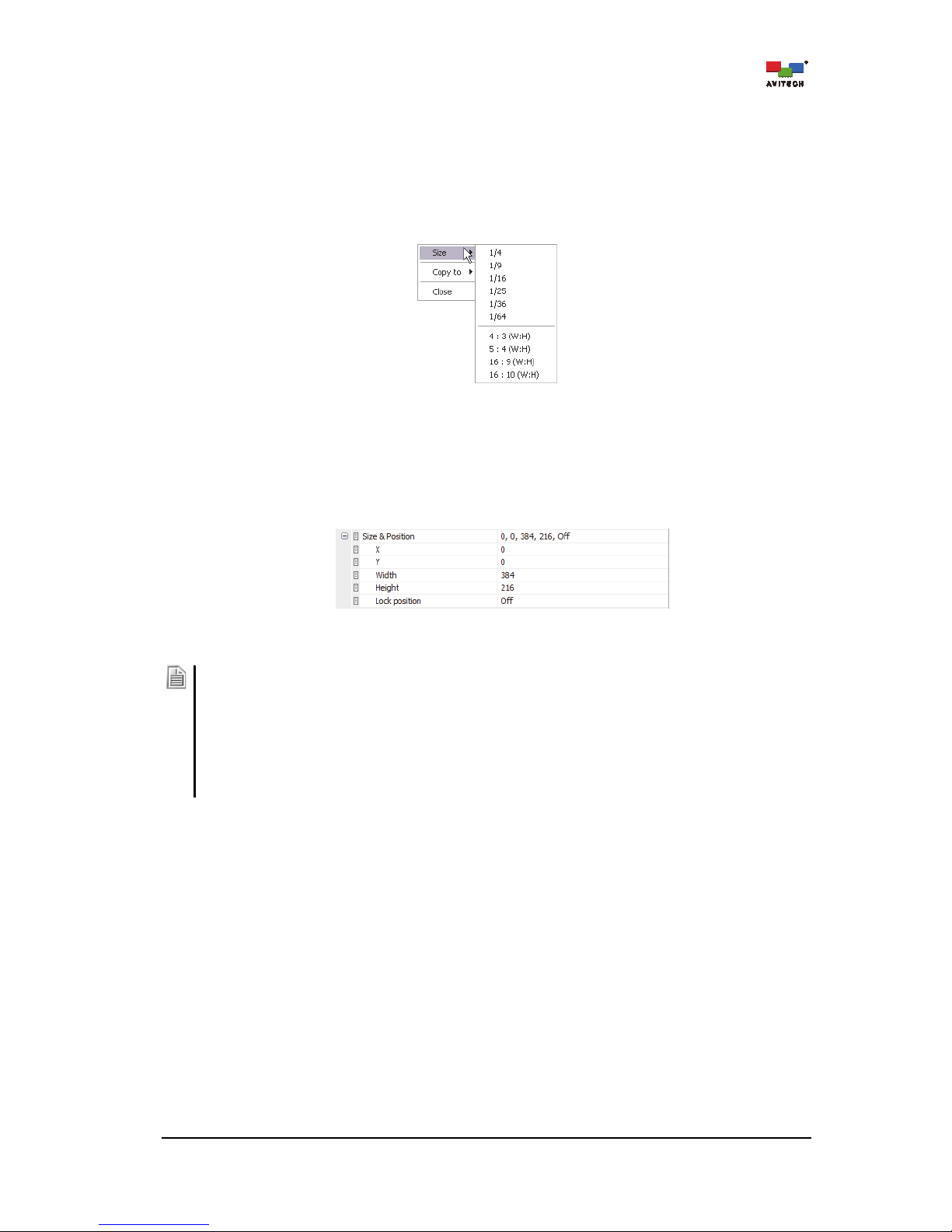
3.4.2 Resize/Reposition Window
Resize a Window
Perform the following steps to resize a window:
Method 1. Right-click a window, then select Size. Select the desired preset size from the
submenu.
Figure 3-13 Phoenix-Q Software: Select a Window Size (right-click a window)
Method 2. In the main display area, resize a window by dragging the border of a window to the
desired size.
Method 3. Select a window in the GUI, and then use the “Properties” menu to specify the exact
size for each window on a pixel-by-pixel basis.
Figure 3-14 Phoenix-Q Software: Specify a Window Size (Properties menu)
Be aware that there is a scaling limit for each window that constrains the maximum/minimum scalable size:
- For an 1080i source signal displayed on Image 2/4, the maximum size is 960×600 pixels.
- When Tally/Meter is enabled, the minimum width of a window allowed is the width of four tallies
combined. The minimum height allowed is the height of four audio meters combined (positioned
horizontally). When Tally/Meter is disabled, the minimum window size allowed is 1/15 the size of the
source signal.
- The width increases by 4 pixels when the main display area of the Phoenix-Q program is shown at a 25%
magnification; and increments by 2 pixels when shown at 50% or 100% magnification. The height always
increments by one pixel.
Reposition a Window
Perform the following steps to reposition a window:
Method 1. In the main display area, drag the center of a window and drop to a new position or use
the left/right/up/down arrow buttons on the keyboard. It will instantly be updated on the
monitor.
Method 2. Another option is to select a window in the GUI, and then use the “Properties” menu to
specify the exact position for each window on a pixel-by-pixel basis.
Page 26

20
3.4.3 Full Screen Mode; Swap Window Contents
Full Screen Mode
Double-click a window to enter full screen mode. Double-click again to return from full screen
mode.
Swap Window
Move cursor to the bottom left hand corner of a window until a letter S appears.
Figure 3-15 Phoenix-Q Software: Swap Window
Click the letter S to select a source window and then click again at a destination window where
you wish to swap the contents from the source. This will swap all the contents and properties of
the source window to the destination window.
3.4.4 Copy Window Properties
Right-click an item (with icon) on the Properties window (except with icon) and click the following to
quickly apply the settings to –
1. All the windows (Card
All)
2. A particular window (Card
Image 1/2/3/4)
3. All the cards belonging to the same (Group/Display)
4. The entire (System)
Figure 3-16 Phoenix-Q Software: Right-click Menu to Easily Apply Settings to Card/Group/System
Under the “Group/Display ###” tab, the properties of a window can be copied to another or all windows
of the same chassis, as well as to the entire system.
Page 27

21
Right-click a window, select Copy to, and click the following to quickly apply the settings to –
1. All the windows (Card
All)
2. A particular window (Card
Image 1/2/3/4)
3. All cards belonging to the same (Group/Display)
4. The entire (System)
Figure 3-17 Phoenix-Q Software: Right-click a Window and Click “Copy to”
The properties that can be copied include the following:
Window size:
1. width
2. height
Label:
1. on/off switch
2. type (ANSI label)
3. font color
4. background color
Aspect ratio:
1. on/off switch
2. sync type
3. fit image size
Safe area:
1. on/off switch
2. horizontal and vertical markers
Meter:
1. on/off switch
2. layout and alarm trigger
3. scale
4. Position
5. group
6. Width
7. meter label
8. color
9. vertical coordinates
10. VU/PPM switch
Image border:
1. on/off switch
2. width
3. color
Video border:
1. on/off switch
2. width
3. color
Page 28

22
3.4.5 Undo/Redo Changes
Click the to undo the previous step; alternatively click the to redo the previous step
that was undone.
To undo or redo multiple actions click the drop-down arrow
symbol beside the undo/redo button, then highlight and click the actions to be undone or redone. Click
the scrollbar to highlight more than six actions.
The following actions will clear the list of undo/redo from their lists:
Load/save preset file
Set display resolution
Group reset
Change group setup
Set to default state
3.4.6 Align Windows
Align a set of windows horizontally or vertically. Choose how the windows will be lined up in relation to
each other. For example, clicking the Align Right button ( ) aligns the right edges of the
windows with each other.
To align a set of windows horizontally/vertically:
Step 1. Select the windows by clicking the first window with the left mouse button and the succeeding
windows using the keyboard’s Ctrl key + left mouse button.
Other applications that are currently running on the same computer with the Phoenix-Q software may also
be using the same Ctrl key + left mouse button hot-key, and it may disable multiple window selection in the
Phoenix-Q software. In that case, close the other program first before using the Ctrl key + left mouse button
in Phoeni
x
-Q.
Step 2. Click one of the following buttons to set how the windows will be lined up with each other. The
alignment will follow the position of the last window selected.
Top
Middle
Bottom
Left
Center
Right
To undo alignment of windows, simply click the Undo button repeatedly according to the number of
windows that were aligned with the last selected window.
Page 29

23
3.4.7 Copy Window Size
These functions allow a set of selected windows to copy the width, height, or size of a designated
window appearing on screen. For example, clicking the Make Same Width button ( )
would set the selected windows to have the same width.
To modify the window size:
Step 1. Select the windows by clicking the first window with the left mouse button and the succeeding
windows using the keyboard’s Ctrl key + left mouse button.
Other applications that are currently running on the same computer with the Phoenix-Q software may also
be using the same Ctrl key + left mouse button hot-key, and it may disable multiple window selection in the
Phoeni
x
-
Q software. Close the other program first before using Ctrl key + left mouse button in Phoeni
x
-
Q.
Step 2. Click one of the following buttons to set the window’s width, height, or size following that of the
last window selected.
Copy width
Copy height
To prevent distortion on the window's image (for "interlaced" input signal), make sure the height of the
image (excluding label and border) IS NOT
smaller than one-half of the vertical active region of input source
(i.e. if resolution is set at 1080i 50Hz then the image’s height must not be less than 600 pixels).
Copy size
To undo the window’s size modification just click the Undo button repeatedly according to the number
of windows that were modified except the last selected windo
w
.
By default the main display area of the Phoenix-Q program is shown at a 25% magnification. This means
the entire layout (single or multiple windows) is visible at one-fourth magnification within the main display
area. Zoom in (50% or 100%) to get a closer look at a window’s detail.
Figure 3-18 Phoenix-Q Software: Set Customized Level Magnification for Viewing Windows
3.4.8 Remove Horizontal/Vertical Spacing
Eliminate the space between a set of windows horizontally or vertically. Choose how the windows will be
lined up in relation to each other. For example, clicking the Remove Vertical Spacing button
( ) eliminates the vertical space between a set of windows.
To position a set of windows side-by-side by removing the horizontal/vertical space:
Step 1. Select the windows by clicking the first window with the left mouse button and the succeeding
windows using the keyboard’s Ctrl key + left mouse button.
Other applications that are currently running on the same computer with the Phoenix-Q software may also
be using the same Ctrl key + left mouse button hot-key, and it may disable multiple window selection in the
Phoenix-Q software. Close the other program first before using the Ctrl key + left mouse button in
Phoenix-Q.
Page 30

24
Step 2. Click one of the following buttons to eliminate the vertical/horizontal spacing between the
windows. The position of the last window selected does not change while those of the other
window(s) change to remove any vertical/horizontal spacing in-between.
Horizontal
Vertical
1. Remove Horizontal Spacing is disabled (grayed-out) if any two consecutive window’s selected are
overlapped horizontally (x-axis perspective).
2. Remove Vertical Spacing is disabled (grayed-out) if any two consecutive windows selected are
overlapped vertically (y-axis perspective).
3.5 Temperature
Click the to open the message window for monitoring the temperature status of Rainier Summit.
Figure 3-19 Temperature: Temperature Log
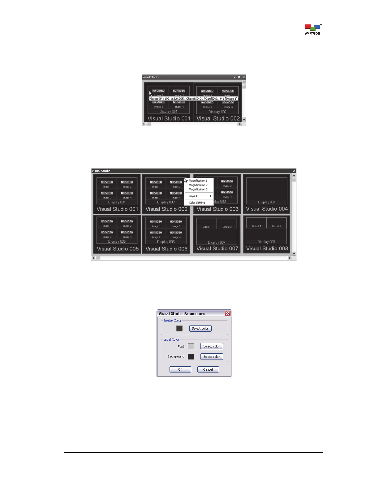
3.6 Visual Studio
For a quick overall view of monitors installed in the studio, use the “Visual Studio” tab to easily view the
present setups.
Step 1. To configure how the monitors will appear in the “Visual Studio” tab, right-click anywhere inside
the “Visual Studio” tab and click Visual Studio Setting.
Figure 3-20 Visual Studio: Click “Visual Studio Setting”
Page 31

25
Step 2. Click to select the particular Group ### (card ID) on the left column.
Click the destination Visual Studio ### (group) on the right column.
Click the right arrow button .
Select other Group ### to belong to a Visual Studio ### group. Multiple Group ### can be
assigned to the same Visual Studio ### group. Finally, click OK to exit the Visual Studio
Setting window.
To remove a particular Group ### from the previously assigned Visual Studio ### on the right
column; click to select it. Then, click the left arrow button .
Figure 3-21 Visual Studio: Assigning Visual Groups
Step 3. On the “Visual Studio” tab, select the desired layout by right-clicking anywhere and then select
Layout. Choose from 2×2 up to 10×10 as possible grid positions, as well as specify a fixed 1
row by “N” columns or “N” rows by 1 column.
Figure 3-22 Visual Studio: Select the “Layout”
If more than one Group ### was assigned to a Visual Studio ### group, initially the Group ### appearing
on the “Visual Studio” tab may be stacked on top of each other. Configure the desired Layout to display the
other Group ###.
Page 32
26
Quick Information
Positioning the cursor on top of a window will alternate between a quick information of the
window and the prompt “Double-click
Group ###” to allow the bringing up of a particular
group’s layout view in the main display area in the “Group ###” tab.
Figure 3-23 Visual Studio: Window Quick Information
Magnification
Right-click anywhere on a window to select from the three available magnifications.
Figure 3-24 Visual Studio: Select the Magnification
Color Setup
To set the border color and label color (font and background), right-click anywhere on a window
and click Color Setting.
Figure 3-25 Visual Studio: Set the Border and Label Color
Page 33
27
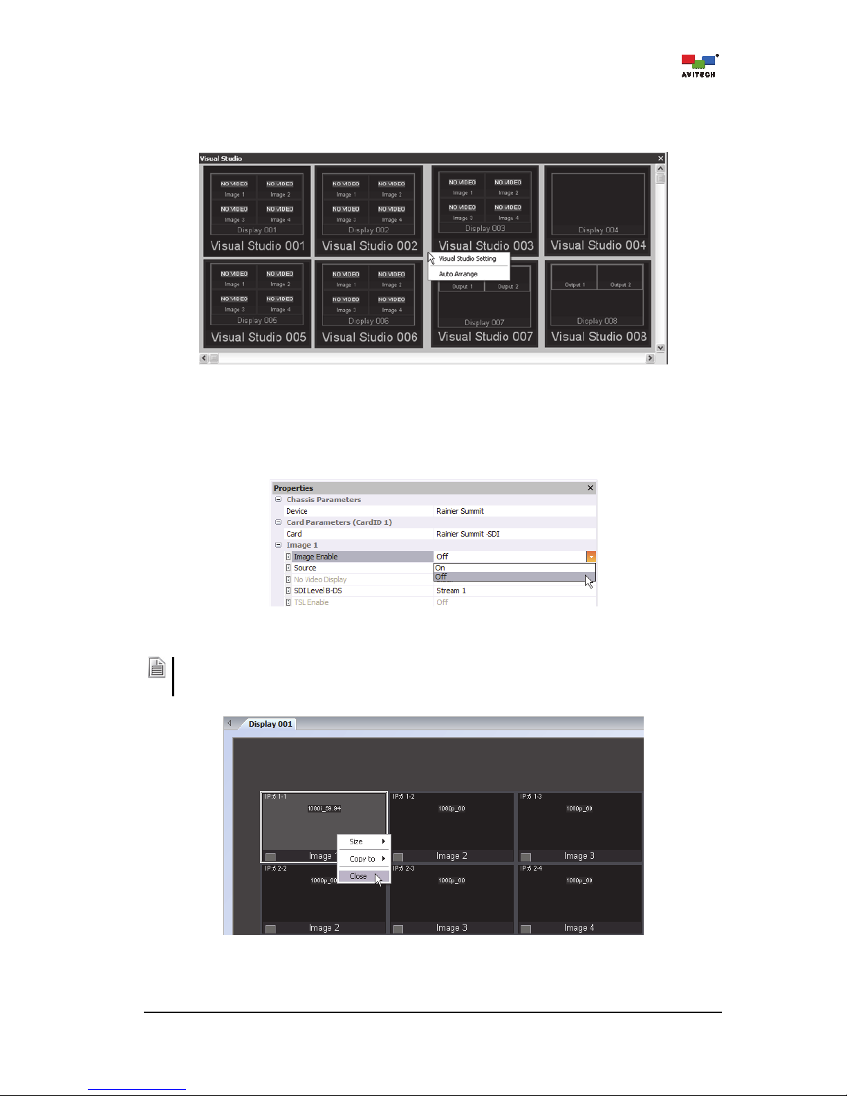
Auto Arrange
Allow the system to automatically arrange the layout of the windows appearing in the Visual
Studio tab.
Figure 3-26 Visual Studio: “Auto Arrange”
3.7 Available Windows
Image windows that are disabled (turned off) reside in a tab called “Available Windows”.
Figure 3-27 Properties Tab: Turning “Off” the Image Window
You can also close (disable) a particular window by clicking Close. The closed window would appear as an
icon under the “Available Windows” tab. To activate the window again, simply drag the window back onto
the main display area.
Figure 3-28 Phoenix-Q Software: Right-click a Window and Click “Close”
Page 34
28
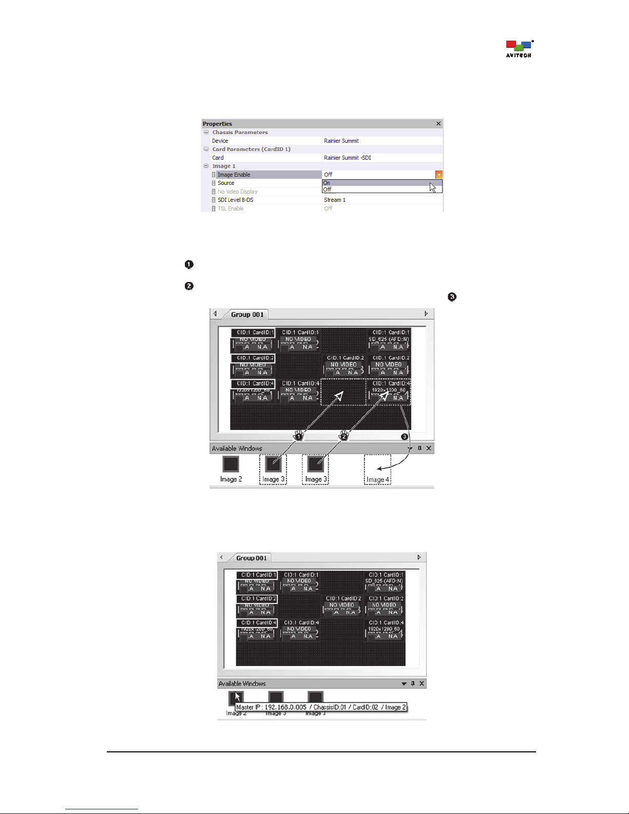
To turn back “on” an image window (re-enable), use any of the two methods listed below:
Method 1. Select the desired image window to be turned on. Then select Image Enable
On in the
“Properties” tab.
Figure 3-29 Properties Tab: Turning “On” the Image Window
Method 2. Drag the window to be enabled from the “Available Windows” tab to the “Group ###” tab.
Action (drag window to an empty location) will allow the selected window to appear in the
previously empty space.
Action (drag window on top of another window) will cause the former occupant window to
be disabled (turned off) and be moved to the "Available Windows" tab .
Figure 3-30 Properties Tab: Turning “On” the Image Window
Placing the mouse pointer on top of a window residing in the “Available Windows” tab displays
information about the image window.
Figure 3-31 Available Windows Tab: Image Window Information
Page 35

29
3.8 Log Window
Aside from letting you view the various system messages in Phoenix-Q, you can export the log
messages as a text file. This is most helpful when monitoring incidences of video loss/freeze/black,
audio high/low/loss/ out of phase, metadata Active Format Description (AFD) display and closed caption
detection.
Step 1. Right-click anywhere inside “Log Window” tab and when the menu appears, click Export.
Figure 3-32 Log Window: Right-click Menu “Export”
Step 2. Assign a filename and click Save to store the data.
Figure 3-33 Phoenix-Q Software: Save Log Window Information
Page 36
30
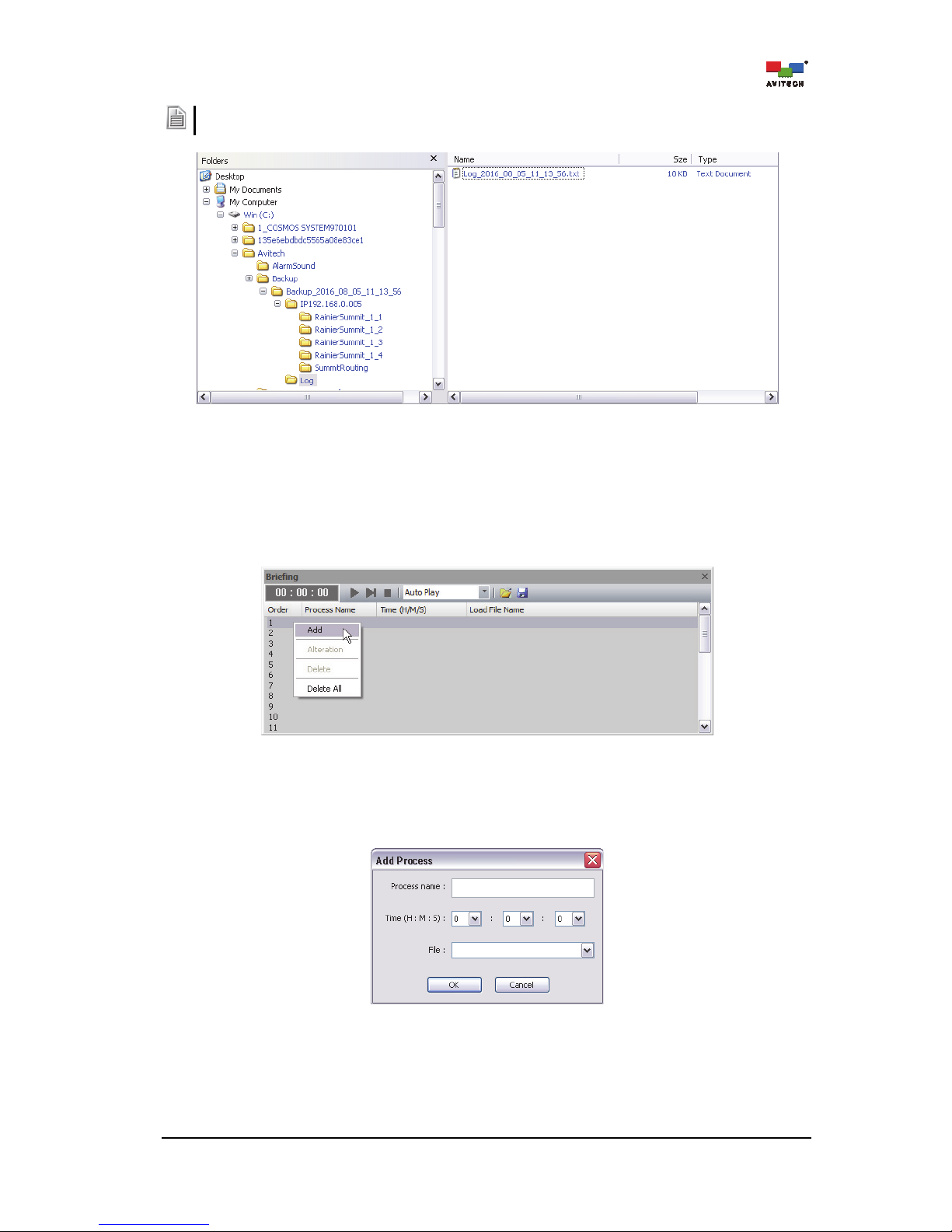
Refer to the computer’s hard drive (C: \Avitech\Backup\Backup_date_time\Log\ folder) for various system
log message text files exported from the device.
Figure 3-34 Phoenix-Q Software: Location of the Saved Log File
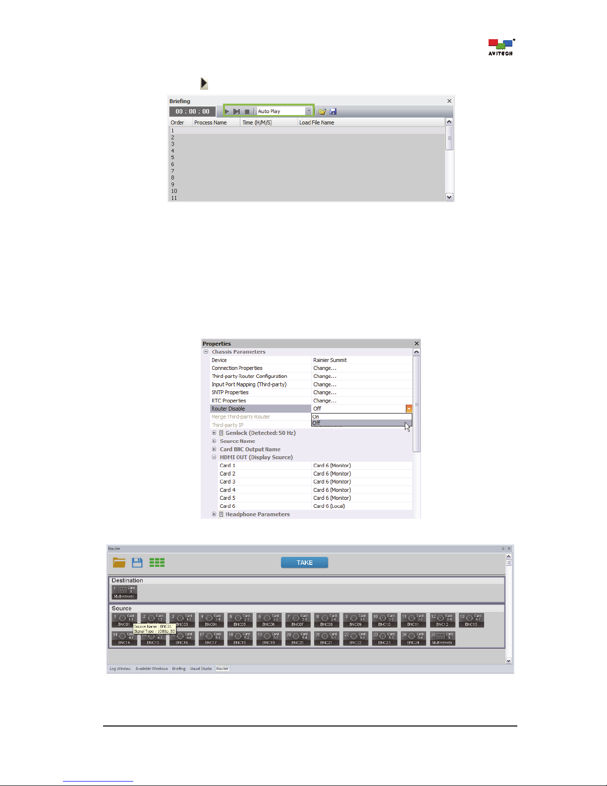
3.9 Briefing
This function allows cycling between layout presets for a slideshow effect.
Step 1. Right-click the numeric title bar under the “Briefing” tab and when the menu appears, click Add.
Figure 3-35 Briefing: Click “Add”
Step 2. Enter the Process name, specify the Time (H : M : S), and then select the previously saved
preset File (refer to section (3.1) “File Menu” for more information on saving presets). Click OK
to continue. Continue adding new processes for “briefing.”
Figure 3-36 Phoenix-Q Software: “Add Process” Window
Page 37
31
Step 3. On the drop-down menu, select Auto Play, Auto Play (Repeat), Manual, or Manual (Repeat).
Then click play to start viewing the slideshow.
Figure 3-37 Briefing: Select the Type of Playback
3.10 Router
Enable routing of source signals to any or multiple windows for monitoring. The next figure shows the
user interface of the “Router” tab for routing control. Placing the mouse cursor over an input icon will
show the input source’s information such as Source Name / Signal Type.
The router function is disabled by default. To turn on this function, locate Router Disable under the
PropertiesChassis Parameters menu of Phoenix-Q and turn it Off.
Figure 3-38 Phoenix-Q: Chassis Parameters Panel
Figure 3-39 Phoenix-Q: Router Tab
Page 38
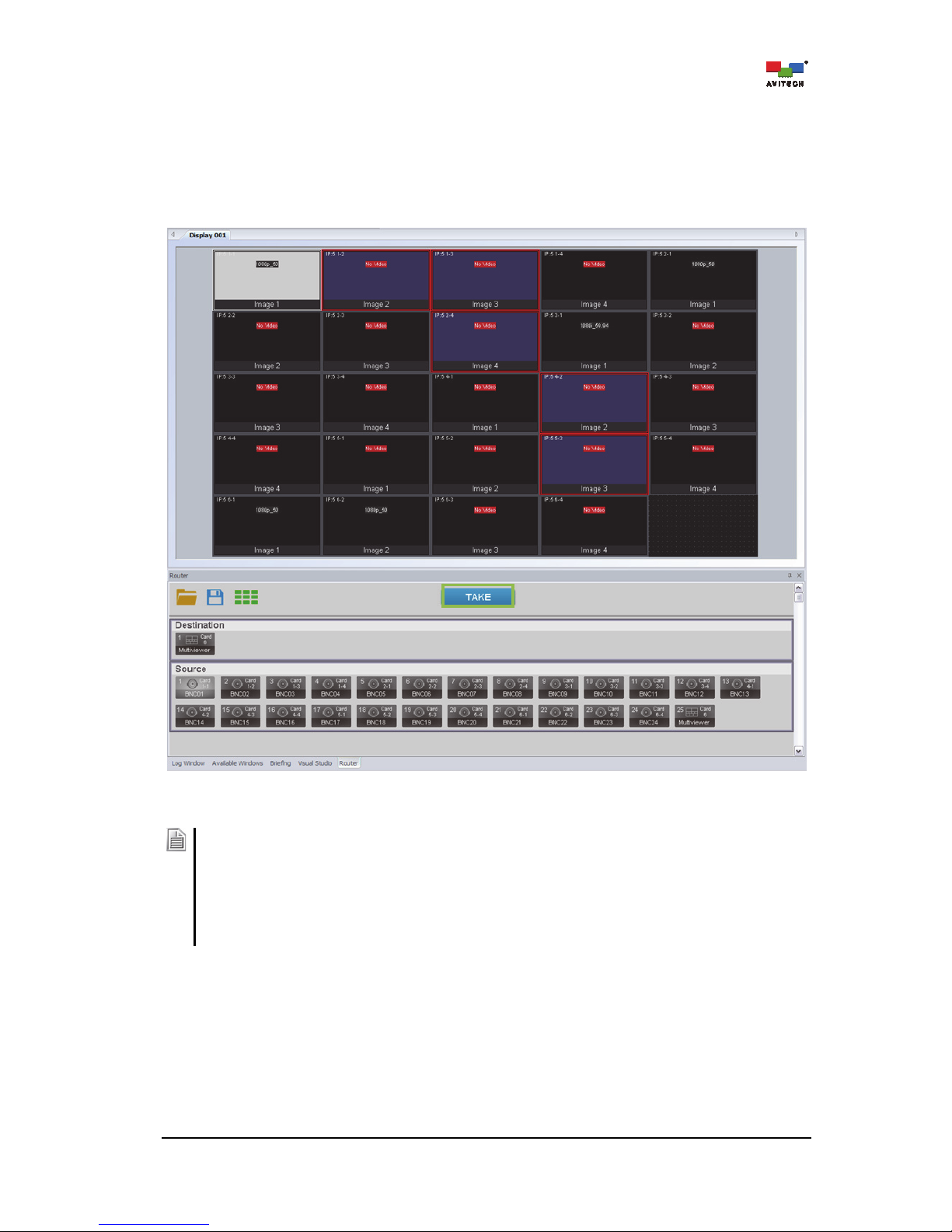
32
To set video routing,
perform the following steps
:
Step 1. Click any element of the Rainier Summit and the router UI will appear on the “Router” tab.
Step 2. Select a source signal to route by first clicking its input signal icon under the “Router” tab, and
then select the router destination(s) by clicking one or more windows on the main display area.
Click TAKE to apply the routing.
Figure 3-40 Router: Routing the Source Signal Process
When setting up video routing:
1. Left-click on the target input port. On the main display area, any window already routed from this input
will turn white in its border and green in its background.
2. Left-click a new window to be designated as the routing destination and it will turn red in its border, and
blue in its background (viewed from the main display area). Left-click this window again to cancel
routing to this designation; its window border and background color will revert back.
3. Click TAKE to confirm the routing. On the main display area, the window with a newly routed source
signal will turn white in its border, and green in its background.
Page 39
33
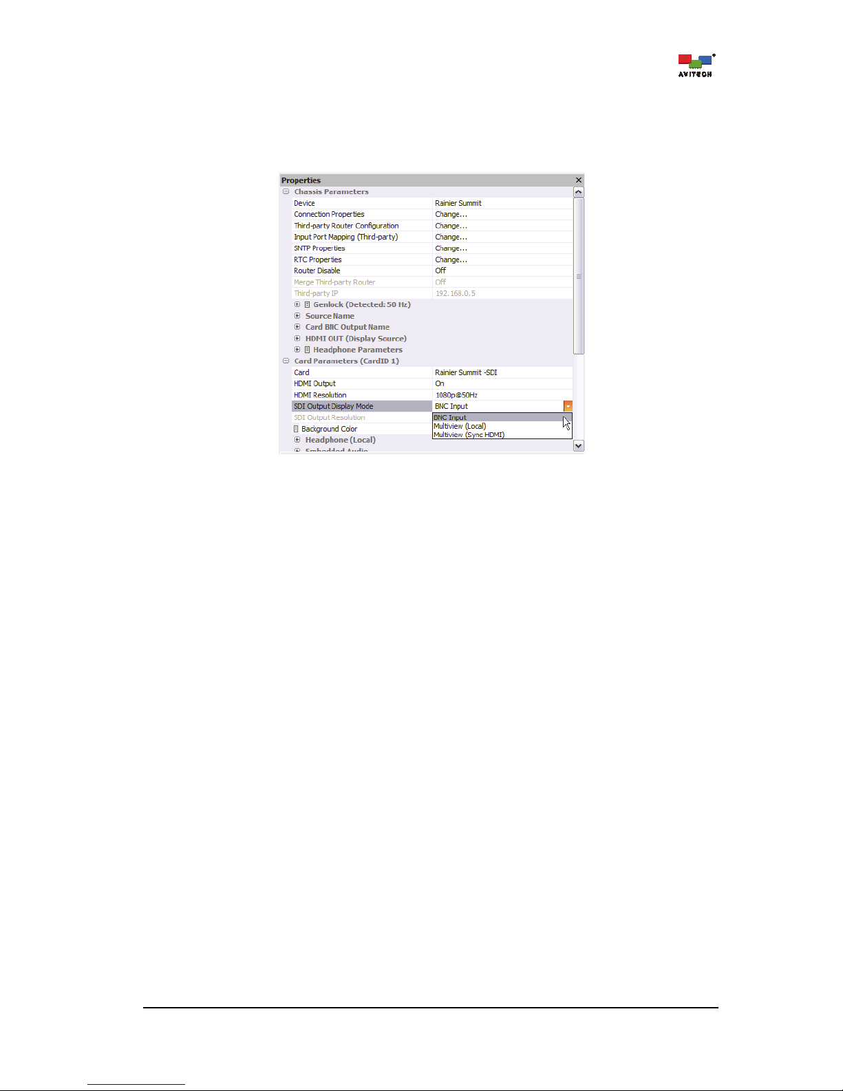
To set video routing to SDI OUT,
perform the following steps
:
The SDI Output Display Mode of a card is set to Multiview (Sync HDMI) by default. To change the
output display mode function, locate SDI Output Display Mode under PropertiesCard Parameters
menu of Phoenix-Q and select BNC Input from the drop-down menu.
Figure 3-41 Phoenix-Q: Card Parameters Panel
Step 1. Click any element of the Rainier Summit and the router UI will appear on the “Router” tab.
Page 40
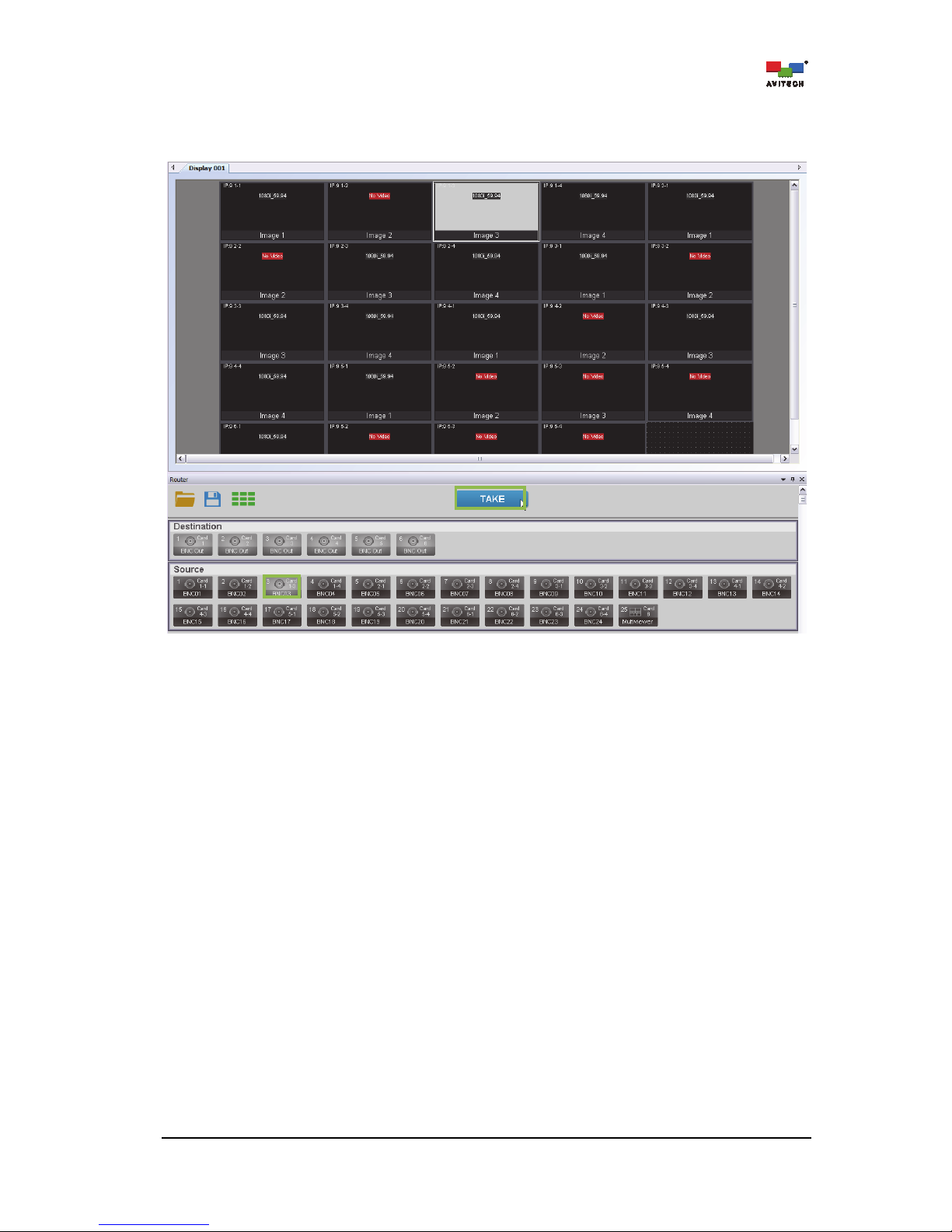
34
Step 2. Select a source signal to route by first clicking its input signal icon under the “Router” tab, and
then select the router destination by clicking one or more on the destination display area. Click
TAKE to apply the routing.
Figure 3-42 Router: “Source Routing to SDI Out” Process
Page 41
35
4. Basic Setup Using the Phoenix-Q Software
This chapter continues the discussion on the various functions of the Phoenix-Q software for setting up
the Rainier Summit, as well as familiarization of the menus found in the Phoenix-Q software.
Some items appearing on the menus of the Phoenix-Q software may not be available for the Rainier
Summit (grayed-out).
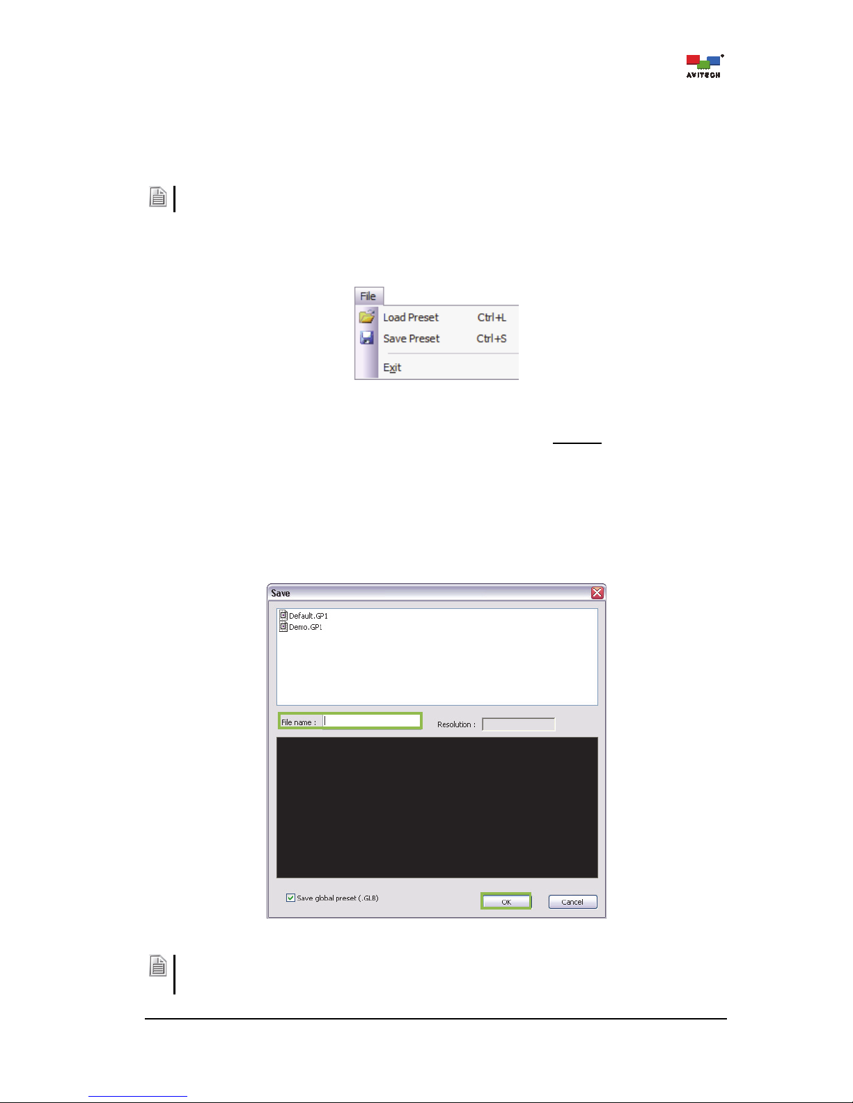
4.1 File Menu
Figure 4-1 Phoenix-Q Software: File Menu
All the presets created are stored in the Rainier Summit’s flash memory, NOT ON
the computer running
the Phoenix-Q software. To save a preset and write it to the internal flash memory of the Rainier Summit,
perform the following steps:
Step 1. Configure the window layout on the main display area to how you want it to be displayed.
Step 2. Click File and then Save Preset.
Step 3. Enter a unique filename for the preset, and click OK to save. Repeat these steps for each
additional preset.
Figure 4-2 Phoenix-Q Software: Enter Unique Filename for Preset
1. The file extension GP# will be added to the filename of a group’s preset.
2. Click to select Save Global Preset (with checkmark) to save a group preset that can be applied to all
the groups. The file extension GLB will be added to the filename.
Page 42

36
Delete a file appearing on the Save window by right-clicking the filename and clicking Delete.
Figure 4-3 Phoenix-Q Software: Delete File in Save Window
To delete all the files appearing on the window, right-click anywhere inside the window (except on the files)
and click Delete All. When the confirmation window appears, click OK to proceed.
Figure 4-4 Phoenix-Q Software: Delete All Preset Files Confirmation
Step 4. After creating presets load the file to be the master layout which gets loaded when the Rainier
Summit is powered on by clicking Load Preset.
Page 43

37
Step 5. Select a saved file and then click OK to load the preset.
Opening a preset file with “GP#” as filename extension loads a single group preset; while
opening a preset file with “GLB” as filename extension loads a preset that applies to all groups
(global preset).
Figure 4-5 Phoenix-Q Software: Load Preset File
Similar to the Save window, delete a file appearing on the Load window by right-clicking the filename and
clicking Delete. To delete all the files appearing on the window right-click anywhere inside the window
(except the filename itself) and click Delete All. When the confirmation window appears, click OK to
proceed.
Step 6. Click Exit to close the Phoenix-Q software. By clicking Yes to confirm saving, all the changes
would be saved to the configuration file “System.json” in the device‘s flash memory.
4.2 Edit Menu
Figure 4-6 Phoenix-Q Software: Edit Menu
Edit Menu
Undo Click Undo to cancel the previous step.
Redo Click Redo to repeat the previous step that was cancelled.
Font Type Click Font Type to set the Font, Font style, and Size.
Table 4-1 Phoenix-Q Software: Edit Menu Description
Page 44

38
Font Type: Click Font Type to select the Font, Font style, and Size. Then, click OK.
Figure 4-7 Phoenix-Q Software: Set Font Properties
For Windows 7: When using the Phoenix-Q in a different language other than English, the Font “Arial”
might not appear as the default font-type. This may cause the label appearing in the window to appear
askew. Perform the following steps to return the default font type to Arial.
Step 1. Click Control Panel and when the next screen appears, click Appearance and
Personalization.
Step 2. On the next screen, click Change Font Settings under Fonts.
Step 3. On the next screen, click Font Settings.
Step 4. On the next screen, click to unselect the Hide fonts based on language settings checkbox.
Then click OK to exit.
Step 5. On the Phoenix-Q software, click to select Arial as the default Font and click OK.
4.3 View Menu
Figure 4-8 Phoenix-Q Software: View Menu
View Menu
Toolbars and
Docking Windows
Enable (with checkmark) or disable the display of any of the toolbars or
windows as well as Customize the display. *See figure (4-9)
Status Bar
When selected (with checkmark) the status bar is displayed on the bottom
of the Phoenix-Q software. Click to select or unselect.
Application Look
Click Application Look to select the overall design and theme of the
Phoenix-Q software. *See figure (4-11)
Table 4-2 Phoenix-Q Software: View Menu Description
Page 45

39
Toolbars and Docking Windows:
Enable (with checkmark) or disable display of Standard toolbar, Available Windows panel, Log
Window panel, Group View panel, Properties panel, Briefing panel, as well as Customize display.
Figure 4-9 Phoenix-Q Software: “Toolbars and Docking Windows” Menu
Customize:
Click Customize to design the look of the menus and commands appearing on the Phoenix-Q software.
Click the particular folder (Commands, Toolbars, Menu and Options) and then make the necessary
changes. Click Close when finished to exit.
Figure 4-10 Phoenix-Q Software: “Customize the Toolbars” Window
Application Look:
Click Application Look to select the overall design and theme of the Phoenix-Q software. Click the
themes title to view the theme. The “dot” in front of Type 2 signifies that it is the currently selected theme
.
Figure 4-11 Phoenix-Q Software: “Application Look” Menu
Page 46

40
4.4 System Menu
Figure 4-12 Phoenix-Q Software: System Menu
System Menu
Connect or
Disconnect
Connect the computer and Rainier Summit via Ethernet connection; or
Disconnect it. Before connecting make sure that the correct
configurations are entered under the item Communication.
Reconnect
Upon unplugging the Ethernet cable and re-connecting it, click
Reconnect to continue the configuration process.
Configuration
Click Configuration to assign the groupings. Create the configuration of a
particular group (for example move the device to another group as so
desired by dragging the device listed under Group 001 to Group 003) and
then click OK. The Phoenix-Q software will save the configuration file
“S
y
stem.json” to the Rainier Summit’s flash memory.
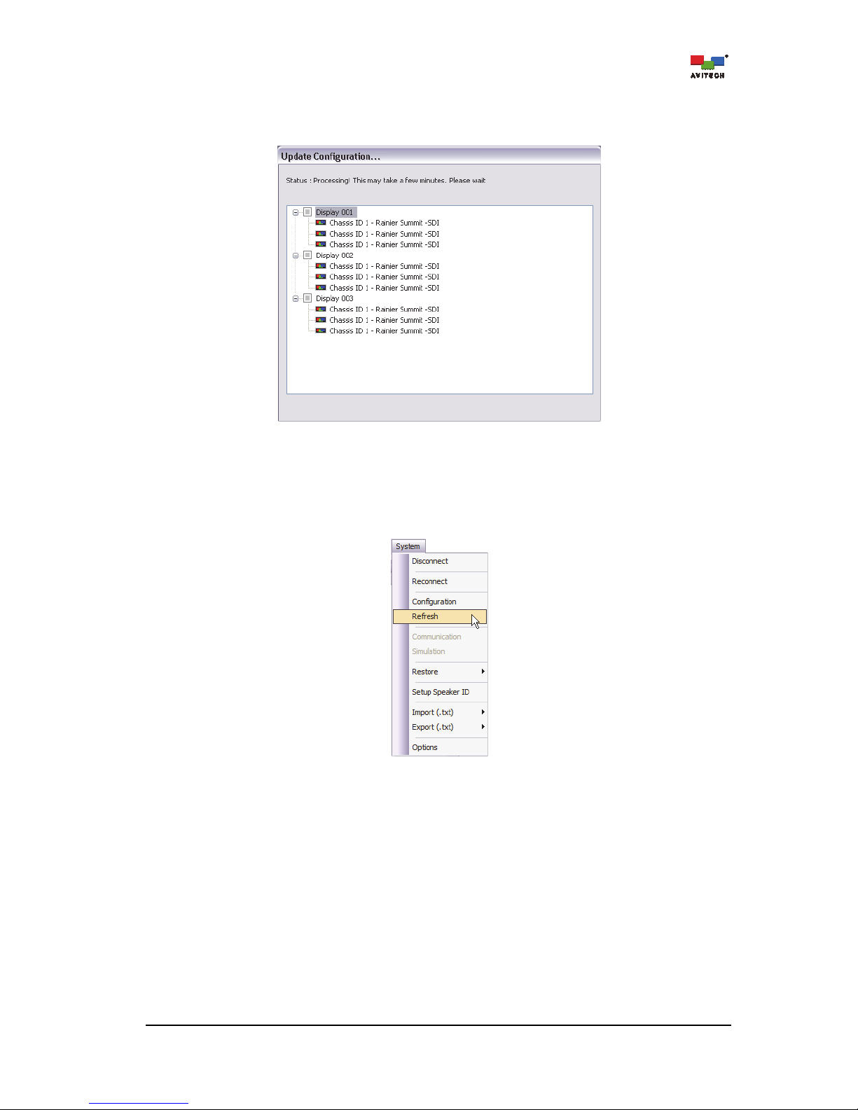
Refresh
Click Refresh to discard the current group configuration and return to the
previous one last saved as a preset.
Note
: This feature is only effective when the Phoenix-Q software stays
connected to the device after group configuration were changed. Upon
Exiting the software, you will need to use the Restore function to recover
the previous group configuration and restore the preset files.
Communication
Click Communication to select the IP Port “Ethernet” mode of
connection between the computer and Rainier Summit.
Note
: This item is not available when the computer is connected to the
Rainier Summit.
Simulation
Note: For factory testing only, this item is not available for normal use.
Restore
To restore a preset follow the steps outlined in figures (4-20 to 4-23).
Setup Speaker ID
Use Setup Speaker ID to set up which speakers to monitor for audio
sources.
Import
Import image labels or alarm sound file from a .txt file. See figures (4-21 to
4-24) for details.
Export
Export image labels or alarm sound parameters to be edited externally.
See figures (4-26 to 4-29) for details.
Options
Options opens up a pop-up window to customize a number of default
settings for Phoenix-Q. These settings are organized into the following
categories; System, GeneralExternal Device, and Communication.
See figures (4-30 to 4-48) for details.
Table 4-3 Phoenix-Q Software: System Menu Description
Page 47

41
Configuration: To change the current group configuration setting or add the cards under Idle Group to
the existing group configuration, perform the following steps:
Step 1. Click Configuration.
Figure 4-13 Phoenix-Q Software: “Configuration” Window
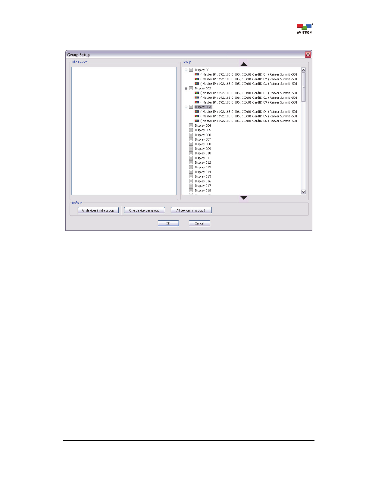
The Group Setup window will appear.
Figure 4-14 Phoenix-Q Software: “Group Setup” Window
Page 48

42
Step 2. To assign the grouping just drag the Idle Device on the left panel to the desired Group # on the
right panel (i.e. Group 003).
Figure 4-15 Phoenix-Q Software: Assign Group # to Idle Device
Page 49
43
After dragging/assigning the card, it is displayed as belonging to the assigned group.
Figure 4-16 Phoenix-Q Software: Idle Device Assigned to Group 003
Page 50
44
Step 3. Repeat the previous step for any additional Idle Device(s). Next, click OK to exit the Group
Setup window. Phoenix-Q will save the configuration file “System.json” to the device’s flash
memory.
Figure 4-17 Phoenix-Q Software: Update Configuration Progress
Refresh: To discard the current group configuration setting and return to the previous group
configuration as well as restore the preset files, perform the following steps.
Step 1. Click Refresh.
Figure 4-18 Phoenix-Q Software: “Refresh” Window
Page 51
45
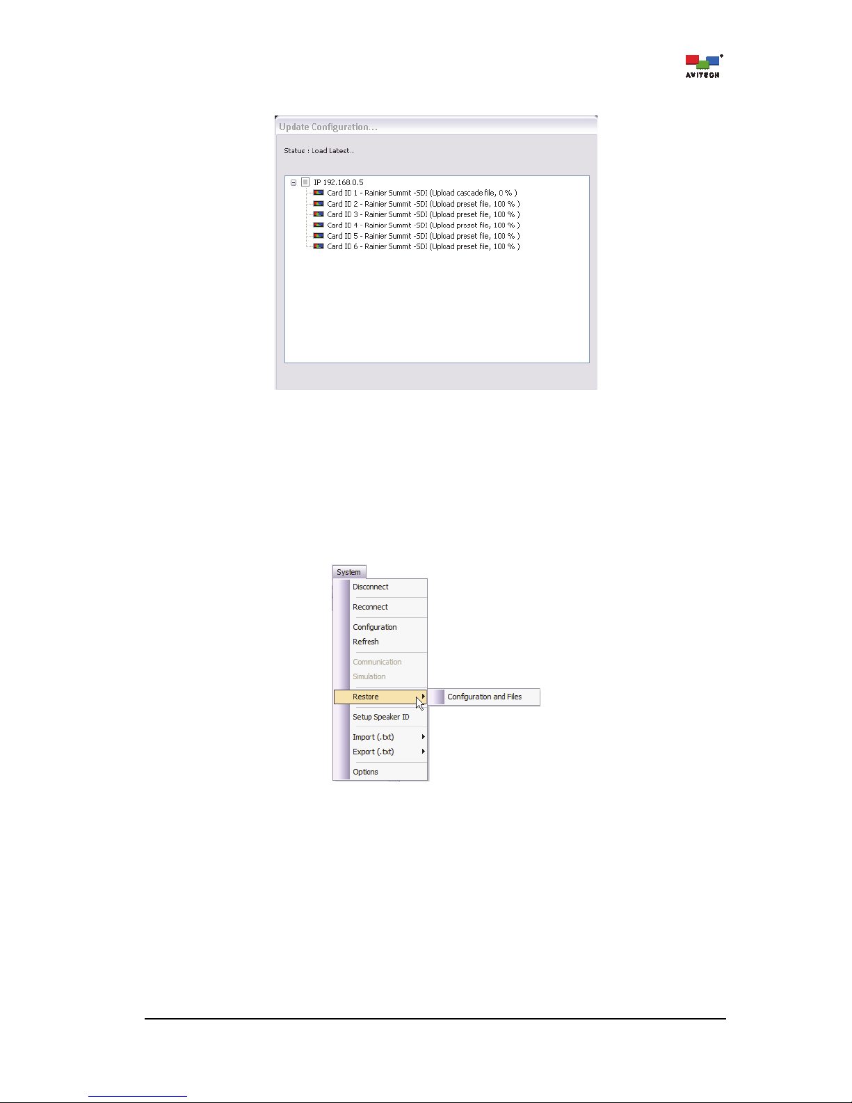
The progress of restoration will be shown.
Figure 4-19 Phoenix-Q Software: “Restore” Progress
Restore: To manually Restore a preset perform the following steps.
Step 1. Set the Rainier Summit to the factory-default value (see Appendix C for details).
Step 2. Make sure that the IP address setting of the chassis being restored matches the old chassis’
setting (if the restoration to be attempted is not for the same chassis).
Step 3. Click System
RestoreConfiguration and Files.
Figure 4-20 Phoenix-Q Software: Click “System”“Restore”“Configuration and Files”
Page 52
46
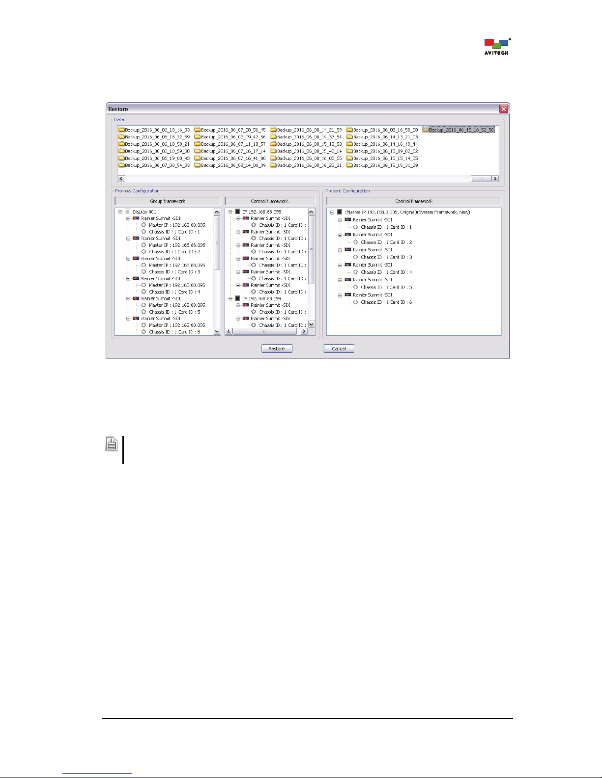
Step 4. The Date window shows the previously saved preset(s) in folders organized by dates. The
Preview Configuration window shows the group setup of the just selected folder. The Present
Configuration window shows the current group setup of the Rainier Summit.
Figure 4-21 Phoenix-Q Software: “Restore” Window
Step 5. Click to select a restore point (i.e. Backup_2016_06_15_16_52_58). The system will compare
the setup listed in the Present Configuration window with the setup listed in the Preview
Configuration window (i.e. Identical, Different, New Device).
When the setup of the Present Configuration window is different from the setup in the Preview
Configuration window (i.e. upon selecting Backup_2016_06_15_16_52_58 folder in the Date window),
manual restoration is not allowed by the system and the Restore button remains grayed-out.
Page 53
47
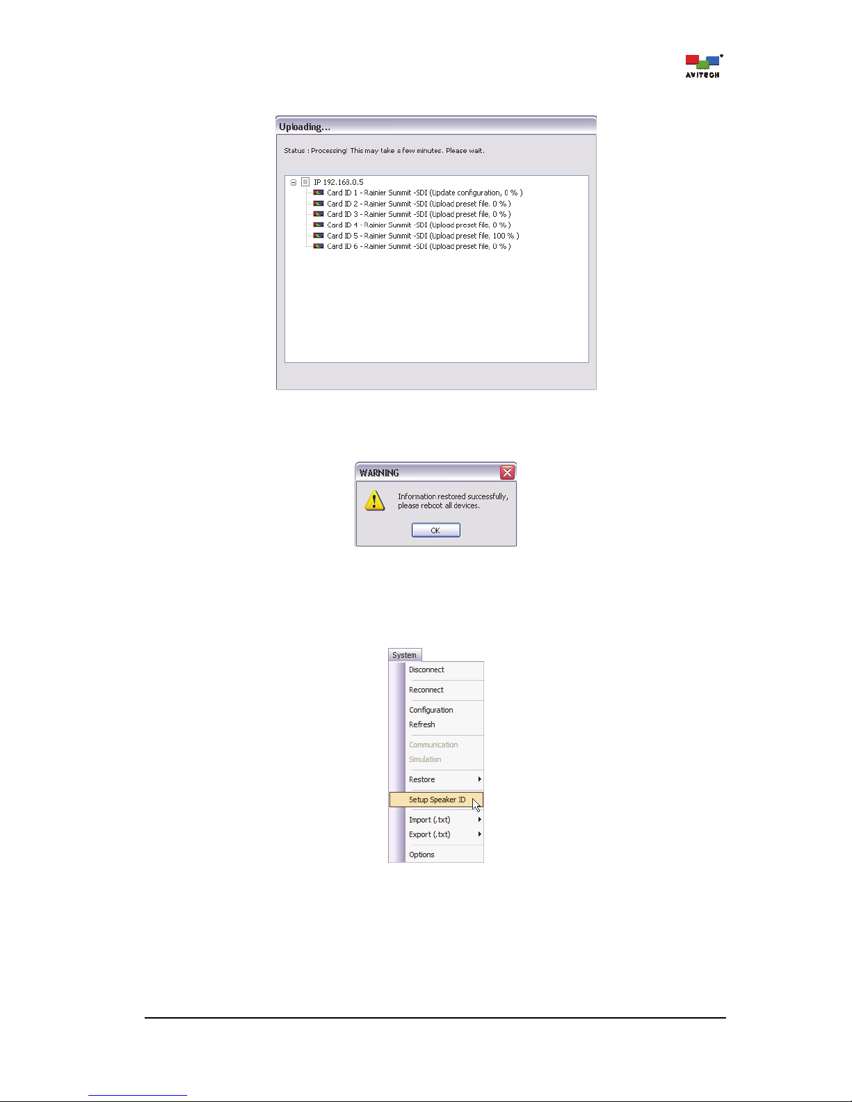
Step 6. Click Restore. The progress of restoration will be shown.
Figure 4-22 Phoenix-Q Software: “Restore” Progress
Step 7. Reboot the Rainier Summit to complete the Restore process.
Figure 4-23 Phoenix-Q Software: Reboot Device
Setup Speaker ID: When there are two or more cascaded chassis, use Setup Speaker ID to assign
each card ID to output to a designated chassis headset connector. Make sure to first assign two
or more chassis cards to the same group.
Figure 4-24 Phoenix-Q Software: Click “System”“Setup Speaker ID”
Page 54
48
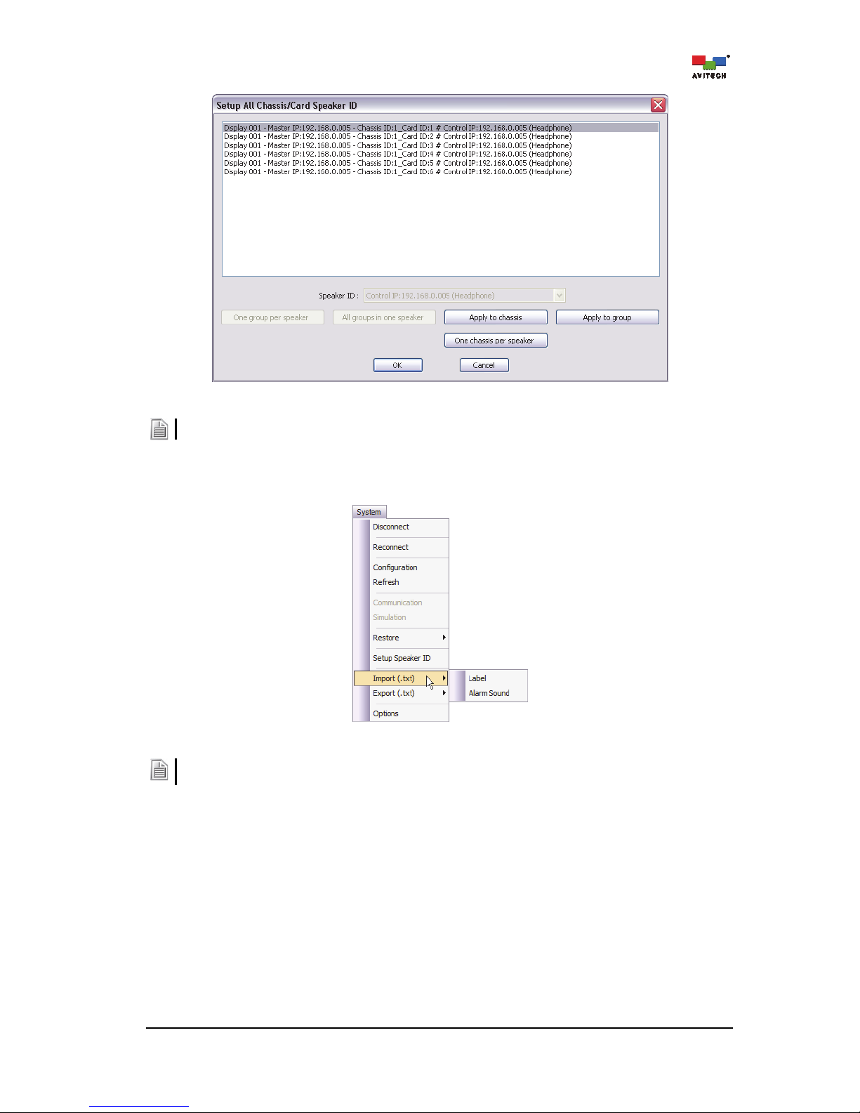
Figure 4-25 Phoenix-Q Software: Card Speaker ID
This item is only available when the computer is connected to the Rainier Summit.
Import and Export Labels / Alarm Sound
Figure 4-26 Phoenix-Q Software: Click “System”“Import/Export Label (.txt)”
1. The Label settings here will affect all the labels of the Groups in the System.
2. Refer to Appendix
A
for complete details on using the Import/ExportAlarm Sound function.
Export the label to be edited externally. The most convenient way is to export the file (label) as:
Label – up to 30 characters; can contain the English characters A–Z, a–z, 0–9
Page 55

49
Step 1. Click SystemExport (.txt)Label and assign a filename. Then click Save.
Figure 4-27 Phoenix-Q Software: Export Label
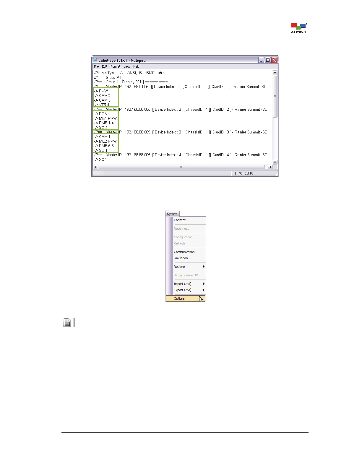
Step 2. Open the exported text file. The first row of text provides a guide to the two types of labels (A for
ANSI Label). Change the label type as desired by typing A after the dash “–” (highlighted as
shown below).
Figure 4-28 Phoenix-Q Software: Change Label Type
Page 56
50
Step 3. Edit the text in the file (highlighted as shown below). When done editing the label, save the txt
file and import it. The on-screen labels will be updated.
Figure 4-29 Phoenix-Q Software: Change Label Text
Options: Opens a pop-up window with system configuration settings.
Figure 4-30 Phoenix-Q Software: Click “System”“Options”
Some of the functions are only available when Phoenix-Q software is not connected to the Rainier Summit.
Page 57
51
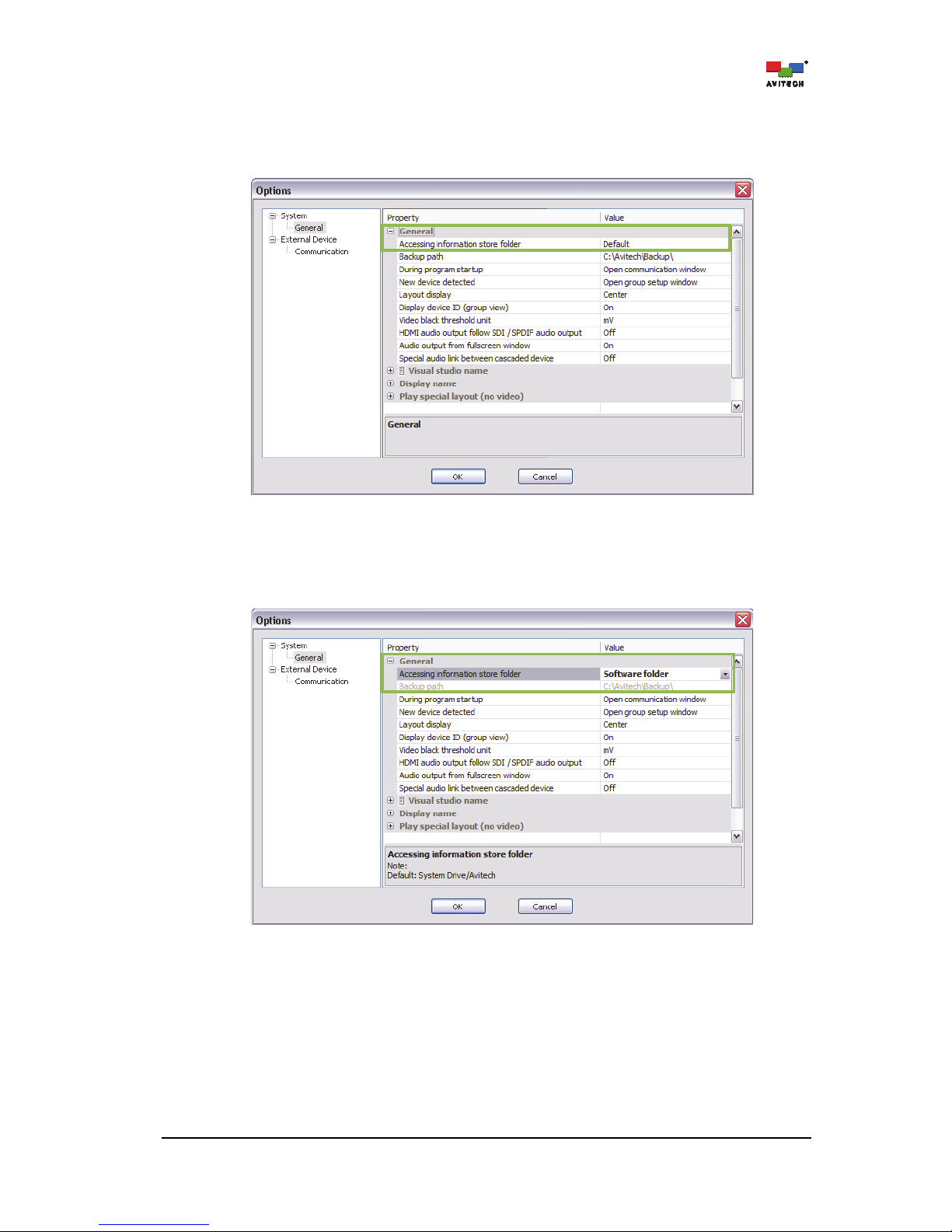
GeneralAccessing information store folder
When Accessing information store folder is set to Default, the Phoenix-Q software will save all
backup files to the computer hard drive’s “C:\Avitech\Backup\” folder (available when Phoenix-Q is
not connected to Rainier Summit).
Figure 4-31 Options: “System”“General”“Accessing information store folder”“Default”
To change the destination folder, click the drop-down button (click the cell’s rightmost portion) and
then select Software folder. All the backup files will then be saved to the same folder where the
Phoenix-Q executable file resides (available when Phoenix-Q is not connected to Rainier Summit).
Figure 4-32 Options: “System”“General”“Accessing information store folder”“Software folder”
Page 58

52
GeneralBackup path
The default backup path “C:\Avitech\Backup\” contains the system configuration, preset files, system
log data, and firmware version information. To change the backup path, type the desired path in the
Value column (available when Phoenix-Q is not connected to the Rainier Summit).
Figure 4-33 Options: “System”“General”“Backup Path”
Or click the select folder button “
…
” (on right-most edge) and when the Select Folder screen appears
choose from the existing folders or click the Make New Folder button to create a new folder. Then
click OK to exit.
Figure 4-34 Phoenix-Q Software: Select Folder Window
Page 59

53
GeneralDuring program startup
Click the drop-down button (click the cell’s rightmost edge) to select Open communication window
that allows the Phoenix-Q program to open the Communication window upon startup.
Figure 4-35 Options: “System”“General”“During Program Startup”
General
New device detected
Click the drop-down button (click the cell’s rightmost edge) and select Open group setup window
that allows the Phoenix-Q program to open the Group Setup window when a new device has been
detected.
Figure 4-36 Options: “System”“General”“New Device Detected”
To prevent an error when detecting a new device it is highly recommended the new device be returned to its
default setting before connecting it to the present setup.
Page 60

54
GeneralLayout display
Click the drop-down button (click the cell’s rightmost edge) to select Center or Upper left corner that
allows the preview window to be displayed in the center or upper left corner.
Figure 4-37 Options: “System”“General”“Layout Display”
General
Display device ID (group view)
To display the device ID information in the Group View panel, make sure Display Device ID (group
view) is enabled (set On). Click the drop-down button [click the Display device ID (group view)
cell’s rightmost edge] to select On.
Figure 4-38 Options: “System”“General”“Display Device ID (Group View)”
General
Video black threshold unit
Set the level (in IRE or mV units) when the signal will be considered black. Click the drop-down
button [click the Video black threshold unit cell’s rightmost edge] to select IRE or mV.
Page 61

55
IRE is a unit used in the measurement of composite video signals. Its name is derived from the initials of the
Institute of Radio Engineers. While mV stands for millivolt.
Figure 4-39 Options: “System”“General”“Video Black Threshold Unit”
General
HDMI Audio output follow SDI / SPDIF audio output
To allow the HDMI audio output to have the same audio output as SDI (Properties portion – Card
Parameters
Headphone (Local)Source), make sure HDMI Audio Output Follow SDI / SPDIF
Audio Output is enabled (set On). Click the drop-down button [click the HDMI Audio Output Follow
SDI / SPDIF Audio Output cell’s rightmost edge] to select On.
Figure 4-40 Options: “System”“General”“HDMI Audio Output Follow SDI / SPDIF Audio Output”
Page 62

56
Upon selecting On the following reminder appears.
Figure 4-41 Reminder upon Enabling “HDMI Audio Output Follow SDI / SPDIF Audio Output”
General
Audio output from fullscreen window
To allow audio output to route to the window that just entered full screen mode, make sure Audio
output from fullscreen window is enabled (set On). Click the drop-down button [click the Audio
output from fullscreen window cell’s rightmost edge] to select On.
Audio output will return to the previous window source upon exiting from full screen mode.
Figure 4-42 Options: “System”“General”“Audio Output From Full Screen Window”
Page 63

57
GeneralSpecial audio link between cascaded device
To allow the audio signal to pass through between cascaded Rainier Summits (both device must
belong to the same group), make sure Special audio link between cascaded device is enabled
(set On). Click the drop-down button [click the Special audio link between cascaded device cell’s
rightmost edge] to select On.
Figure 4-43 Options: “System”“General”“Special Audio Link between Cascaded Device”
General
Visual studio name
Type the Visual Studio group’s new name (up to 30 characters).
Figure 4-44 Options: “System”“General”“Visual Studio Name”
Page 64
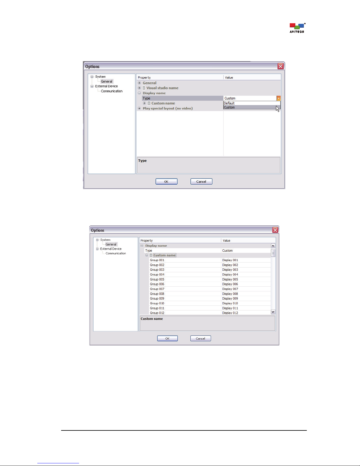
58
GeneralDisplay nameType
To change the group’s displayed name, select Custom. Click the drop-down button [click the Type
cell’s rightmost edge] to select Custom.
Figure 4-45 Options: “System”“General”“Type”
General
Display nameCustom name
Type the group’s new name (up to 30 characters).
Figure 4-46 Options: “System”“General”“Custom Name”
Page 65
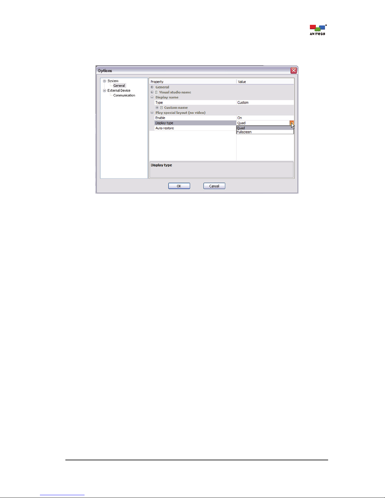
59
Play special layout (no video)
Make sure that Play special layout when No Video occurs is Enabled (set On). Click the dropdown button (click the Display Type cell’s rightmost edge) to select Quad or Fullscreen.
Figure 4-47 Options: “System”“Play Special Layout (No Video)”“Display Type”
Display Type: Quad/Fullscreen
The following sample scenarios may occur:
Sample scenario 1 – a single window loses video signal
Regardless of the present monitor’s window layout, the quad/full screen layout would be displayed
and the single window without video signal would occupy the top-left position/full screen to warn the
user that a particular window has no video signal.
Sample scenario 2 – three windows lose video signal
Regardless of the present monitor’s window layout, the quad layout would be displayed and the three
windows without video signal would occupy the top-left, top-right, and bottom-left positions to warn
the user that the three windows have lost video signal.
Or, the window whose video signal is last detected as missing would occupy the fullscreen as
warning.
Auto Restore
The following sample scenarios may occur:
Sample scenario 1 – a single window loses video signal
Allows the window layout to revert back to where it was before signal loss occurred. Click the dropdown button (click the Auto Restore cell’s rightmost edge) to select On. When Auto Restore is
disabled (set Off) then right-click the window and select Close to allow the window layout to revert
back to where it was before signal loss occurred.
Sample scenario 2 – window #2 has regained video signal out of the three windows that lost video
signal
Allows window #2 that has regained video signal to be removed from the screen. Click the dropdown button (click the Auto Restore cell’s rightmost edge) to select On. When Auto Restore is
disabled (set Off) then right-click the window and select Close to allow the window layout to revert
back to what it was before signal loss occurred. For Quad Display Type (previous item) then window
#3 would occupy the place vacated by window #2. Or, for Full screen Display Type, then the
second-to-the-last window that lost video signal would occupy the whole screen.
Page 66
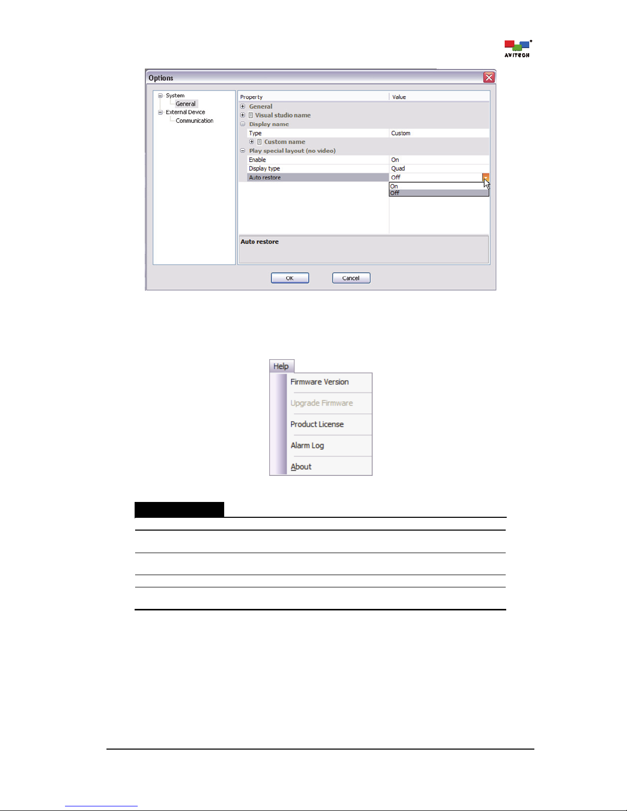
60
Figure 4-48 Options: “System”“Play Special Layout (No Video)”“Auto Restore”
4.5 Help Menu
Figure 4-49 Phoenix-Q Software: Help Menu
Help Menu
Firmware Version
Click to export as a .txt file.
Upgrade Firmware
Click Upgrade Firmware to bring the device’s firmware up-to-date
(see “Firmware Upgrade Reference Guide” for details).
Product License
Click Product License to upgrade the license to an authorized version
(see Appendix G for details).
Alarm Log
Click Alarm Log to check the log data for export as a .txt alarm log file
About
Click About to see a pop-up window displaying information about the
Phoenix-Q software (i.e., version number).
Table 4-4 Phoenix-Q Software: Help Menu Description
Page 67
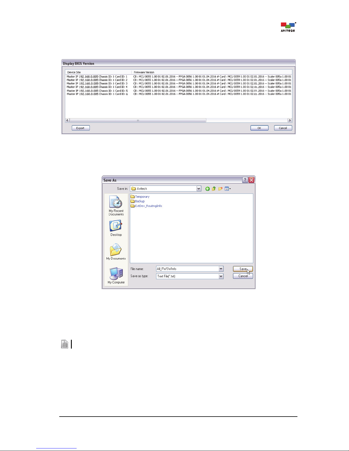
61
4.5.1 Firmware Version
Step 1. Click Firmware Version.
Figure 4-50 Phoenix-Q Software: Firmware Version
Step 2. Click Export.
Step 3. Assign a filename and click Save to store the data.
Figure 4-51 Phoenix-Q Software: Save Firmware Version Information
4.5.2 Upgrade Firmware
Click Upgrade Firmware to bring the device’s firmware up-to-date (see “Firmware Upgrade Reference
Guide for Rainier Summit” for details).
Click “System””Disconnect” first before firmware upgrade.
Page 68
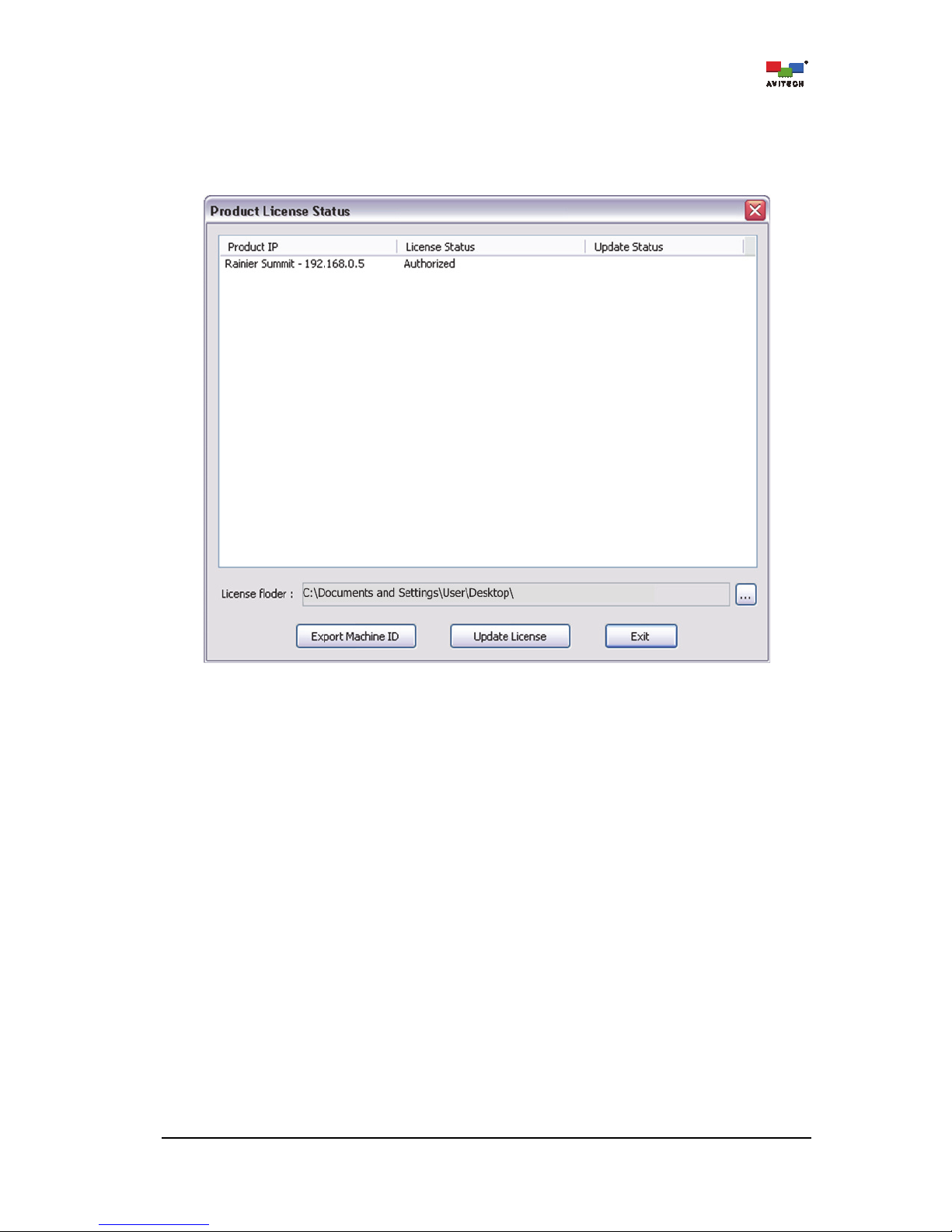
62
4.5.3 Product License
Click Product License to check the license information. There are two License Statuses,
Authorized License – used permanently
Figure 4-52 License Status: Authorized
Page 69
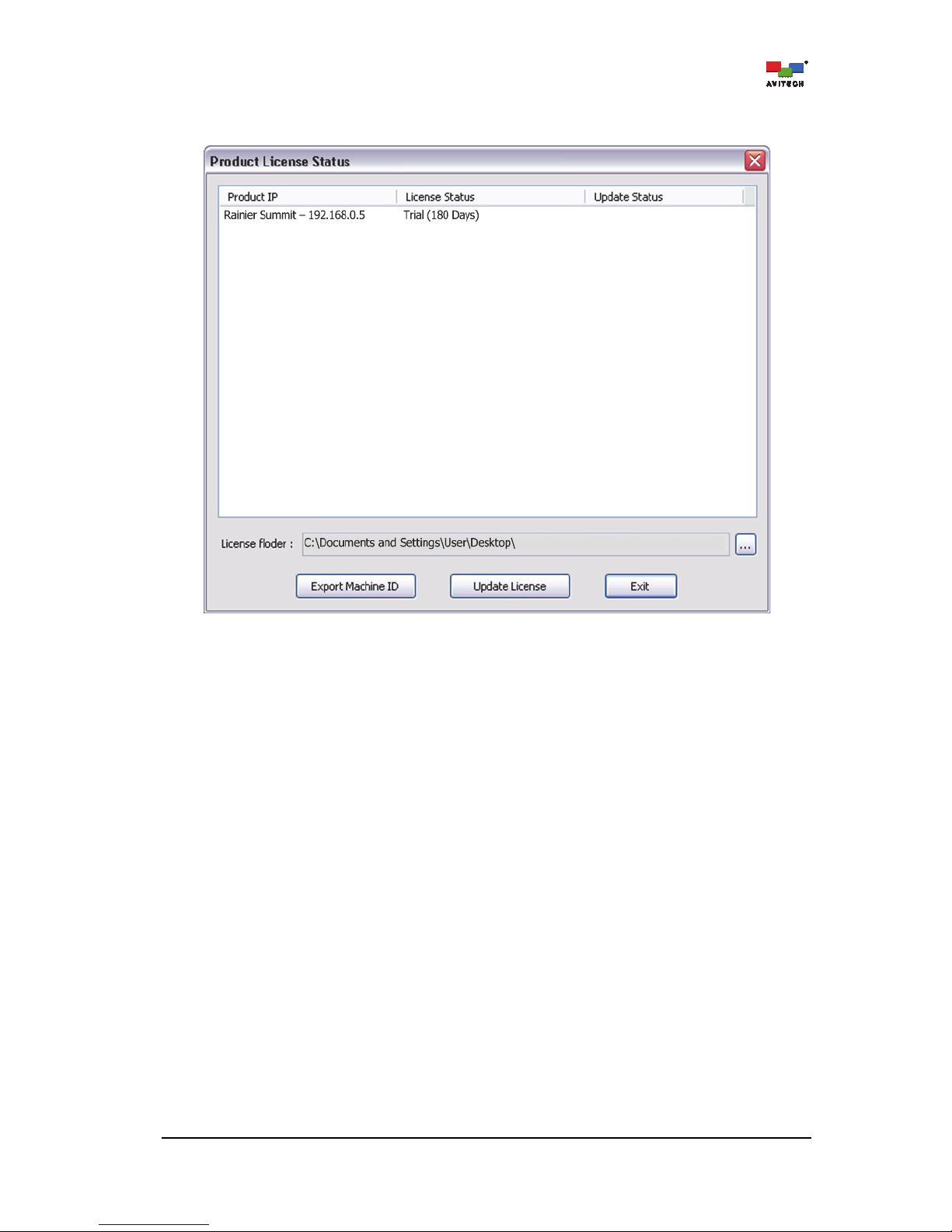
63
Trial License – for a maximum period of 180 days starting from the date of first use of the Phoenix-Q;
and/or from the first use of the Rainier Summit for evaluation purposes. (see Appendix G for details).
Figure 4-53 License Status: Trial
Page 70
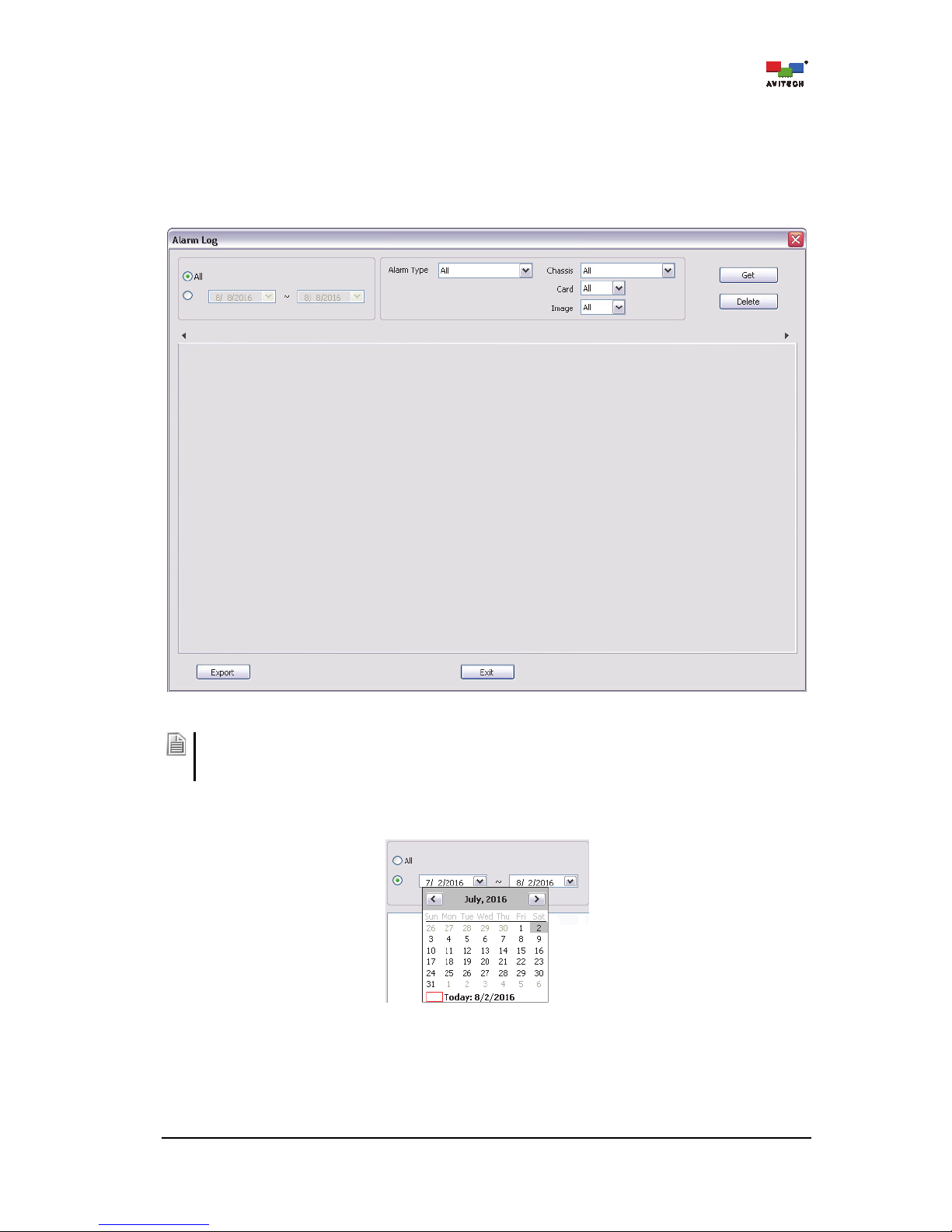
64
4.5.4 Alarm Log
The alarm log of Rainier Summit contains a record of occurrences, such as System Alarm (power
failure, fan failure, temperature too high alarm) / No Video / Video Black / Video Freeze / No Audio.
Click Alarm Log. The Alarm Log window shows the configuration for sorting the alarm data of Rainier
Summit.
Figure 4-54 Phoenix-Q Software: Alarm Log
The alarm log will be only be stored in the USB thumb drive connected to the USB port of the
Control Board. Otherwise, Phoenix-Q must be running and connected to the Rainier Summit for
logging the alarm status.
Step 1. Click All (from the initial date) or manually set the period.
Figure 4-55 Phoenix-Q Software: “Alarm Log”“Date Setting”
Page 71
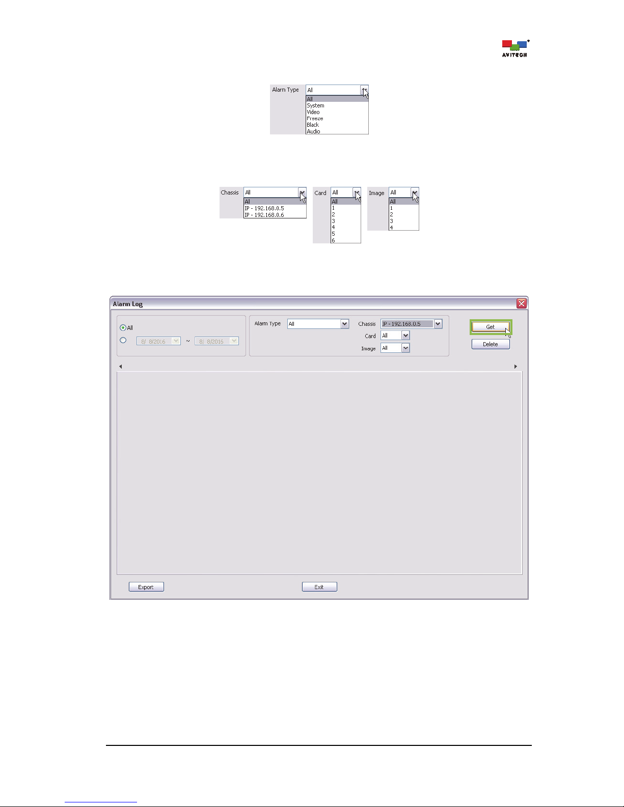
65
Step 2. Select the Alarm Type from the drop-down menu.
Figure 4-56 Phoenix-Q Software: “Alarm Log”“Alarm Type”
Step 3. Select the desired Chassis / Card / Image from the drop-down menu.
Figure 4-57 Phoenix-Q Software: “Alarm Log”“Chassis/Card/Image Setting”
Step 4. Click Get to compile and generate a system alarm log.
Figure 4-58 Alarm Log: Obtain Log (Get)
Page 72
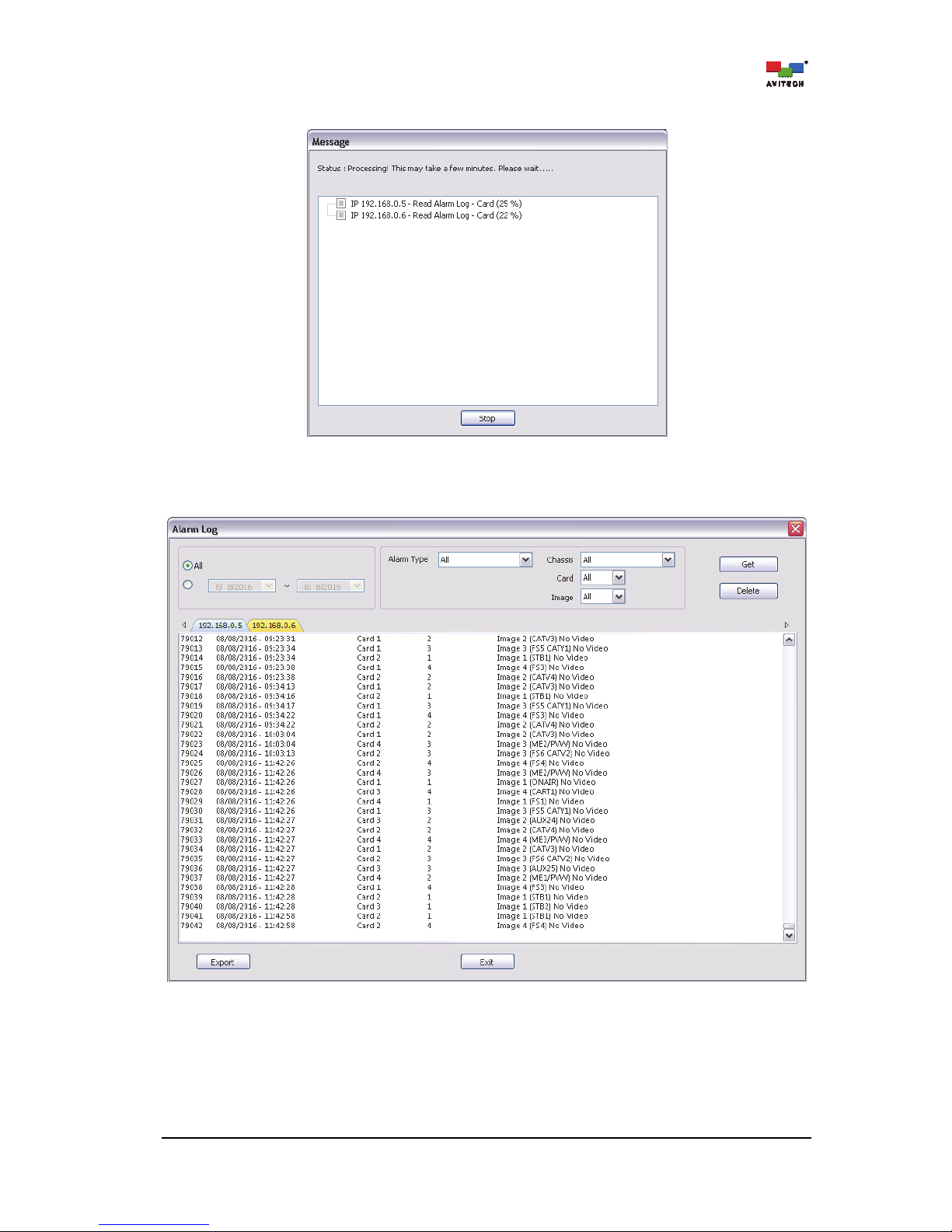
66
The progress of obtaining a log will be shown.
Figure 4-59 Alarm Log: Obtain Log Progress Window
Once the process is complete, the alarm log will be shown via tag naming under a particular
Chassis IP.
Figure 4-60 Alarm Log: Alarm Log Window via Tag Naming
Page 73
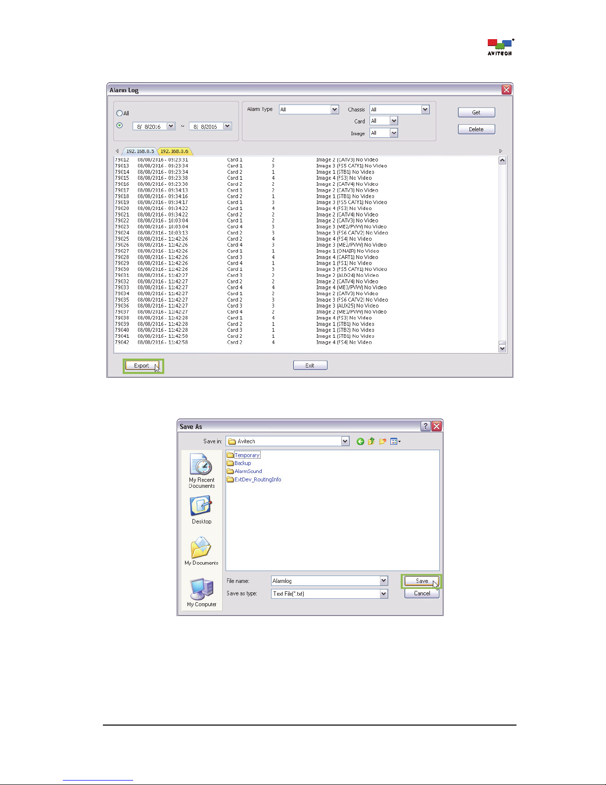
67
Step 5. Click Export to store the alarm log data.
Figure 4-61 Alarm Log: Export Alarm Log
Step 6. Assign a filename and click Save.
Figure 4-62 Alarm Log: Assign a File name for the Alarm Log
Page 74

68
Step 7. Click OK to exit.
Figure 4-63 Alarm Log Export Successful
4.5.5 About
Click About to see a pop-up box showing the Phoenix-Q software information.
Figure 4-64 Phoenix-Q Software: Version Information
Page 75

69
5. Setting the Chassis/Group/Card Properties
To set the properties of the Rainier Summit, click to select the “card” on the Group View window (left
panel) and the Properties window (right panel) would list the parameters available for setup.
Figure 5-1 Phoenix-Q Software: Chassis and Card Properties Window
Page 76

70
5.1 Rainier Summit Properties Setup
Connection Properties
Change . . .
Set the network Connection Properties by entering the IP address, Subnet
mask, Gateway, DNS 1 and DNS 2 to connect.
Note
: This item is only available when Phoenix-Q is disconnected from the master
chassis.
Third-party Router
Configuration
Change . . .
Check/uncheck to “Enable” for the Rainier Summit as the master unit for
managing an upstream third-party router and assign the Source IP of the
master Rainier Summit.
Check/uncheck to Enable a Third-party Device. Currently, third-party devices
supported are TSL, Videohub, and VikinX. Click the respective radio button to
select an upstream third-party device. Make sure to enter the correct UDP (User
Datagram Protocol) Port value that matches the connected router.
Check/uncheck to Enable a SONY switcher. Click the respective radio button to
select an upstream third-party device. Make sure to enter the correct Filter
Address value that matches the connected switcher.
Check/uncheck PSS when Rainier Summit working in conjunction with Pacific
PSS. Assign a specific PSS’ IP.
Check/uncheck Summit when the Rainier Summit upstream video source is
coming from another Rainier Summit’s SDI OUT. Assign a specific Rainier
Summit’s IP.
When configuring, connect the Rainier Summit, the controlling computer and the
Third-party Device to an Ethernet hub via Ethernet
connection. Or connect the
Page 77

71
Third-party Router
Configuration
(Master Rainier Summit) RS-232 port to the Third-party Device.
Note
: To implement TSL other than selecting “Enable”
“TSL UMD Properties” must be “On” and “Display Address / Option” must be
configured.
“Label
Display Type” for the particular Window must be configured “UMD” or
“D-Name/UMD”
Input Port Mapping
(Third-party)
Change . . .
Set the Input Port Mapping by entering the corresponding port number connected
to the Rainier Summit’s input port.
Note
: If the entered port number is equal to “-1”, firmware will ignore it. If the value
matches the third-party routing’s setting then the UDM label will be applied and
displayed in the label of the Windows.
SNTP Properties
Change . . .
Enable the SNTP feature. Upon selecting RTC, it allows the clock to synchronize
the time with an external SNTP time server.
Set the SNTP time server IP address for synchronizing the clock time with an
external SNTP time server.
Note
: When SNTP is Enabled, RTC clock will synchronize the module’s clock with
the SNTP time server.
RTC Properties
Change . . .
Set the time appearing on the real time clock (RTC).
Page 78

72
Router Disable
On / Off
Turn on or off the built-in video router function.
Note
: When Router Disable is On, the “Router” tab will not function.
Merge Third-party Router
On / Off
Turn on to control the third-party router.
Note
: This item is not available when Router Disable is Off.
Third-party IP
IP address
Select the IP address of the chosen third-party router to control.
Note:
Available IP address(es) for selection are configured in the item Third-Party
Router Communication.
Genlock (Detected: Hz)
Frame Rate (Freerun Mode)
(50 / 59.94 / 60)
Detect and sync the reference input for Genlock function (frame synchronizer). Or
manually select the reference input frame rate. After changing the frame rate,
confirm that the intended sync source is connected to the multiviewer’s Ref input
port and then reboot the device.
Source Name
BNC 1 – BNC 24
(Card 1:1 – BNC 1 ~
Card 6:4 – BNC 24)
Enter the text string to appear as the image window’s on-screen label.
Note
: This text string will be shown on the label when the label’s Display Type is
set as Source Name (S-Name).
Card BNC Output Name
Card 1 – Card 6
Enter the text string to appear as the image window’s on-screen label.
Note
: This text string will be shown on the label when the label’s Display Type is
set as Source Name (S-Name).
HDMI OUT
(Display Source)
Card 1/2/3/4/5/6
(Card 1/2/3/4/5/6,
Local / Monitor)
Select a display source as the output to each of the card’s HDMI OUT port. Select a
card’s Local multiview source as the output source or the last card’s Monitor
source as the output source to another card’s HDMI OUT port.
Note
: The last card can only select local multiview source as its output to display.
Headphone Parameters
Mute
(On / Off)
Turn off the audio output coming from the headphone connected to the audio output
port.
Sound
(Stereo / Mono Left / Mono
Right)
Select whether audio output is one-sided or coming from both sides of the
headphone.
Volume (dB)
(–64 up to 12)
Set the volume level of audio output from the headphone.
Analog gain (%)
(0.0, 14.3, 28.6, 42.9, 57.1,
71.4, 85.7, 100.0)
Adjust the proper volume level (previous item) and proper audio analog amplifier's
gain (this item) to achieve the best SNR (signal-to-noise ratio). Signal-to-noise ratio
is a measure used in comparing the level of a desired signal to the level of
background noise.
Page 79

73
The following table shows the Properties setting for Card Parameters in the Rainier Summit.
Card Parameters
HDMI Output
(On / Off)
Turn on or off the HDMI output.
HDMI Resolution
Set the display resolution.
Note
: The frame rate of the HDMI output resolution will depend on the Genlock
input frame rate. If the Genlock input frame rate is 60Hz, then the HDMI output
resolution will only list all the supported 60Hz output resolution.
SDI Output Display Mode
(BNC Input /
Multiview (Local) /
Multiview (Sync HDMI))
Select whether the SDI output is coming from the BNC input, Multiview layout
(Local) or from another main board’s cascaded multiview layout (Sync HDMI).
SDI Output Resolution
(1080p / 1080i)
Set the SDI display resolution.
Note
: The frame rate of the SDI output resolution will depend on the Genlock input
frame rate. If the Genlock input frame rate is 60Hz, then the SDI output resolution
will only list all the supported 60Hz output resolution.
Background Color
Specify the display’s background color. Click Other for more color choices
(Standard tab) or customize color (Custom tab) by setting Hue/Saturation/
Luminance as well as Red/Green/Blue values.
Headphone (Local)
Source
Select the source of the audio signal to be played on the headphone. Image 1/2/3/
4 embedded audio, or pass through embedded audio.
Channel
Select the source of the audio signal to be played on the headphone.
(Group 1/2/3/4 CH1/CH2, Group 1/2/3/4 CH3/CH4)
Audio Delay
(On / Off)
Turn on or off the audio delay.
Audio Delay (0 to 8191
Millisecond
Allows adjustment of headphone audio output to maximize the relative timing of
the audio and video signals on the monitor wall display. Use the slider to adjust the
audio monitoring delay until the headphone audio output and video are well
synchronized on the monitor wall display.
Note
: By design, the audio signal is approximately 5.56 ms.
Embedded Audio
SDI Output
Mute
(On / Off)
Turn on or off the audio output coming from the SDI OUT port.
Source
Select the source of embedded audio signal that will be outputted through the SDI
OUT port (Image 1/2/3/4 embedded audio, or pass through embedded audio
(Local/Monitor)).
Note:
1. When the SDI Output Display Mode is Multiview (Local), the embedded audio
will pass through the local audio source, likewise the SDI Output Display Mode
is Multiview (Sync HDMI), and the embedded audio will pass through from the
monitor’s audio source.
2. When the SDI Output Display Mode is BNC Input, the audio source cannot be
selected.
Page 80
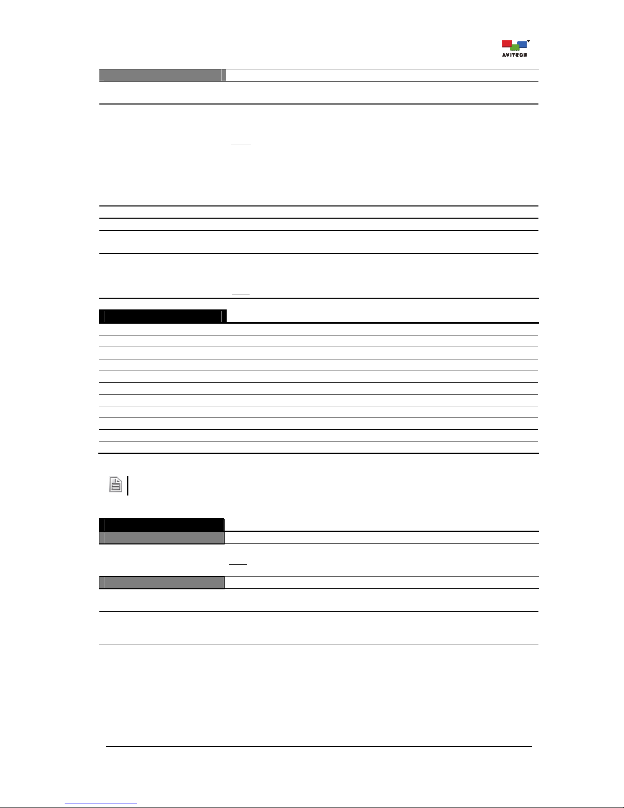
74
HDMI Output
Mute
(On / Off)
Turn on or off the audio output coming from the HDMI OUT port.
Source
Select the source of the embedded audio signal that will be outputted through the
HDMI OUT (Image 1/2/3/4 embedded audio, or pass through embedded audio
(Local/Monitor)).
Note:
1. When the HDMI Output (Display Source) is Card (Local), the embedded
audio will pass through the local audio source, likewise the HDMI Output
(Display Source) is Card (Monitor), and the embedded audio will pass through
from the monitor’s audio source.
2. The pass through embedded audio Source of Card 6 is fixed at local and cannot
be changed.
Primary Group Assign the primary embedded audio group to (Group 1/2/3/4).
Secondary Group Assign the secondary embedded audio group to (Group 1/2/3/4).
Delay Enable
(On / Off)
Turn on or off the audio delay.
Audio Delay
(1 to 2700 millisecond)
Allow adjustment of embedded audio output to maximize the relative timing of the
audio and video signals on the monitor display. Use the slider to adjust the audio
monitoring delay until the audio output and video outputs are well synchronized.
Note
: By design, audio signal is approximately 10.6 ms ahead of video.
Alarm String
No Video
Indicate when the input video signal is missing.
Video Freeze
Indicate when the input video signal is detected to be frozen.
Video Black
Indicate when the input video signal is detected as a black screen.
No Audio
Indicate when the embedded audio input signal is absent.
Audio High
Indicate when the embedded audio input volume exceeds the upper threshold.
Audio Low
Indicate when the embedded audio input volume exceeds the lower threshold.
Audio Out of Phase
Indicate when the embedded audio input signal is detected as out of phase.
No C.C
Indicate when the closed caption data is missing.
C.C 708
Indicate when the closed caption service (C.C 708) is missing.
C.C 608
Indicate when the closed caption service (C.C 608) is missing.
Timecode Loss
Indicate when the SDI embedded timecode signal is missing.
1. Alarm text strings are user-definable and will appear on an Image window’s dedicated alarm area.
2. Currently, the Rainier Summit only supports the English text string for customized alert messages.
Clock
Preset Time
Index 1 – Index 8
Set the preset time “duration” to be used in digital counter clock(s).
Note
: This item is not available when both of the two Digital Clock(s) in each card
are Off.
Preset Time Trigger
Enable
(On / Off)
Activate the “clock preset time” counter feature.
Source
(RTC / LTC #1 / LTC #2 /
LTC #3 / VITC)
Select the clock source as the reference time for triggering Index # of the preset
time.
Page 81

75
Clock
Time Zone
Select the appropriate time zone.
Daylight Saving Time
(On / Off)
Enable the clock Source to take into account the one-hour difference in real time
due to “daylight saving time” (DST).
Trigger 1 – 10
Enable
(On / Off)
Activate Trigger # for triggering specific preset time Index #.
Clock ID
(Digital 1 / Digital 2)
Select a digital clock to display the preset time Index # when being triggered.
Trigger Time
Change . . .
Set the time for the preset time Index # to be triggered.
Preset Time ID
(1/2/3/4/5/6/7/8)
Select the preset time Index # to be triggered.
Count
(Up / Down)
Select the counting method: Up (forward) or Down (reverse).
Digital Clock #1 / #2
Enable
(On / Off)
Allow the display of digital clock on screen.
Page 82

76
Digital Clock #1 / #2
Template
Change . . .
Select the digital clock template.
Digital Clock Template
Hide (Fullscreen mode)
(On / Off)
Allow the display of clock during full screen mode.
Size
X
Y
Specify the location of the clock appearing on screen by setting the X and Y
coordinates.
Width
Height
Specify size of clock appearing on screen by setting the Width and Height values.
Note: The minimum size for RTC clock template is 196 × 110; 128 × 53 for the
counter clock template.
Page 83
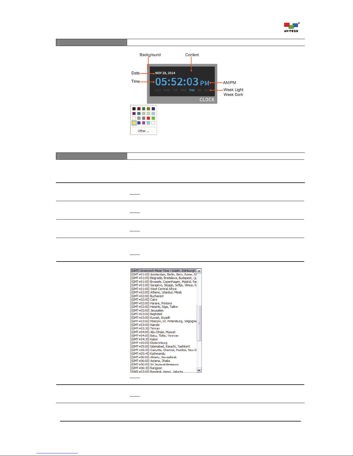
77
Color
Background
Content
Time
AM/PM
Date
Week Light
Week Dark
Digital clock components for setting the color
Set the digital clock components’ color appearing on screen. Click Other for more
color choices (Standard tab) or customize the color (Custom tab) by setting the
Hue/Saturation/Luminance as well as the Red/Green/Blue values.
Time
Source
(RTC / LTC #1 / LTC #2 / LTC
#3 / VITC)
Activate the timecode feature by selecting the RTC, LTC or Counter template. The
RTC timecode feature allows the synchronization of the clock with an external
SNTP time server; or with a RTC time. The IP port on the rear of the chassis can
control, as well as receive, timecode information simultaneously.
Preset Time ID
(1/2/3/4/5/6/7/8)
Select the preset time Index #.
Note
: This item is only available when selecting Counter_Template in Template for
Digital Clock #.
Pause
(On / Off)
Allow the pausing/resumption of the time count.
Note
: This item is only available when selecting Counter_Template in Template for
Digital Clock #.
Count
(Up / Down)
Select the counting method: Up (forward) or Down (reverse).
Note
: This item is only available when selecting Counter_Template in Template for
Digital Clock #.
Daylight Saving Time
(On / Off)
Enable the clock Source to take into account the one-hour difference in real time
due to daylight saving time (DST).
Note
: This item is not available when selecting Counter_Template in Template for
Digital Clock #.
Time Zone
Specify the desired time zone.
Note
: This item is not available when selecting Counter_Template in Template for
Digital Clock #.
Format
(12-hour / 24-hour)
Select the clock display format.
Note
: This item is not available when selecting Counter_Template in Template for
Digital Clock #.
Page 84
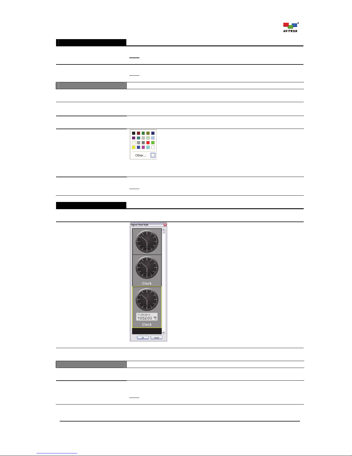
78
Digital Clock #1 / #2
Date Format
(DD_MM / MM_DD)
Select the date and month display format.
Note
: This item is not available when selecting Counter_Template in Template for
Digital Clock #.
Display Frame
(On / Off)
Enable the source’s frame (linear timecode frame) value to be shown on screen.
Note
: This item is only available when selecting LTC_Template in Digital Clock 1
or Digital Clock 2.
Label: Clock
Enable
(On / Off)
Allow the display of the clock’s label.
Position
(Bottom / Top)
Change the clock’s label position (default label position is “Bottom”).
Align
(Right / Center / Left)
Change the alignment of the clock’s label string (default label aligns to the “Right”).
Label Font Color
(On / Off)
Specify the clock’s label font color. Click Other for more color choices (Standard
tab) or customize the color (Custom tab) by setting the Hue/Saturation/
Luminance as well as the Red/Green/Blue values.
Text
Change the content of the clock’s label text string (default label is “Clock”).
Note
: Currently, the Rainier Summit only supports English, Japanese, Korean,
Chinese (Traditional), Chinese (Simplified) text string.
Analog Clock #1 / #2
Enable
(On / Off)
Allow the display of analog clock on screen.
Template
Change . . .
Select the analog clock template.
Hide (Fullscreen mode)
(On / Off)
Allow the display of clock during full screen mode.
Size
X
Y
Specify the location of the clock appearing on screen by setting the X and Y
coordinates.
Width
Height
Specify the size of the clock appearing on screen by setting the Width and Height
values.
Note: The minimum size for template_1 is 128×128, template_2 is 128×148, and
template_3 is 128×181.
Page 85
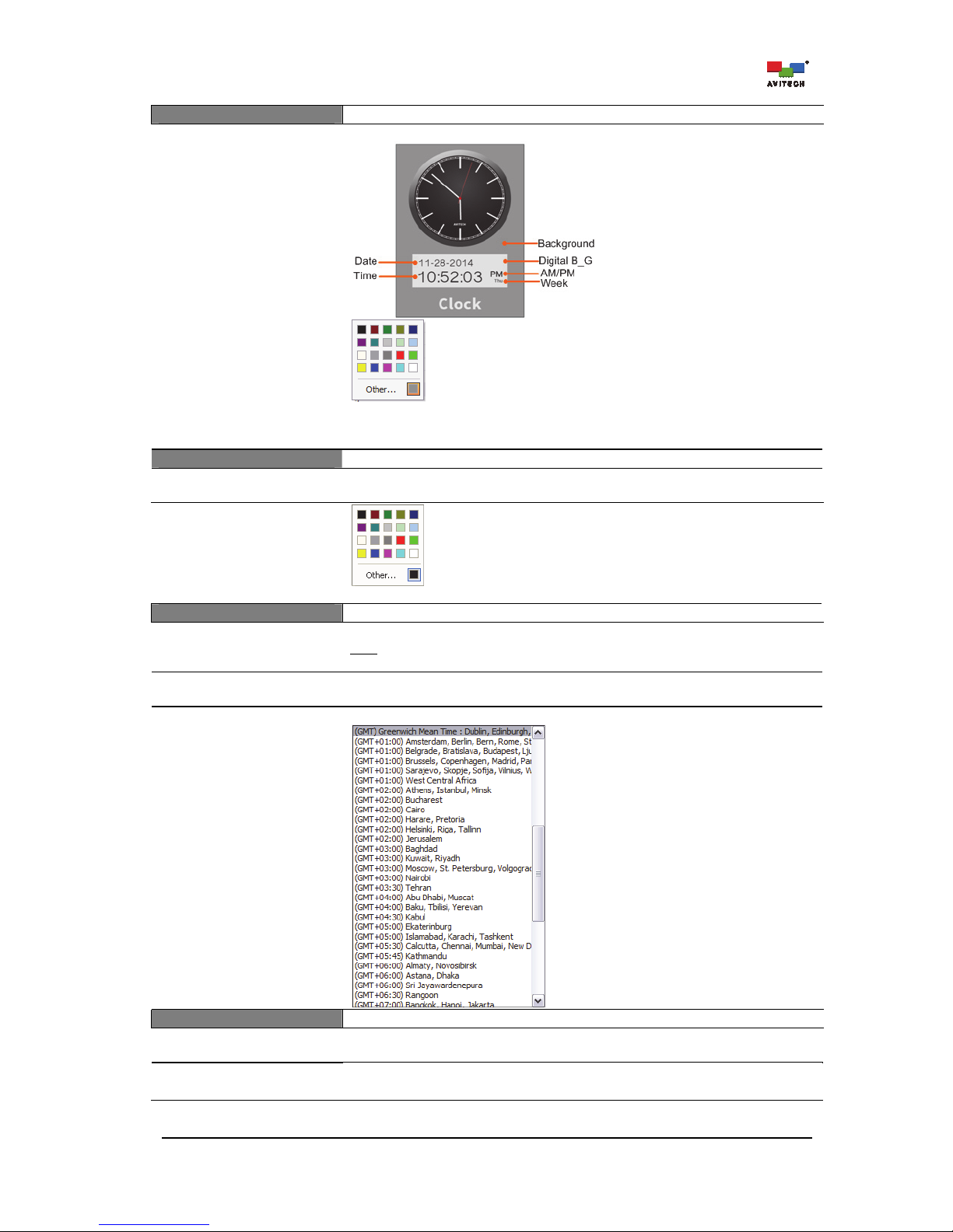
79
Color
Background
Time
Date
Week
AM/PM
Digital B_G
Analog clock components for setting the color
Set analog clock components’ color appearing on screen. Click Other for more
color choices (Standard tab) or customize color (Custom tab) by setting Hue/
Saturation/Luminance as well as Red/Green/Blue values.
Border
Width
(0 – 6 pixel)
Set border width for the analog clock (default border width is “2”).
Border Color
Change analog clock’s border color for each pixel/line (Line 1/2/3/4/5/6).
Time
Date Format
(DD_MM / MM_DD)
Select the date and month display format.
Note
: This item is only available when selecting Template_3 in Template for
Analog Clock #.
Daylight Saving Time
(On / Off)
Enable the clock Source to take into account the one-hour difference in real time
due to daylight saving time (DST).
Time Zone
Specify the appropriate time zone.
Label: Clock
Enable
(On / Off)
Allow the display of the clock’s label.
Position
(Bottom / Top)
Change the clock’s label position (default label position is at the “Bottom”).
Page 86
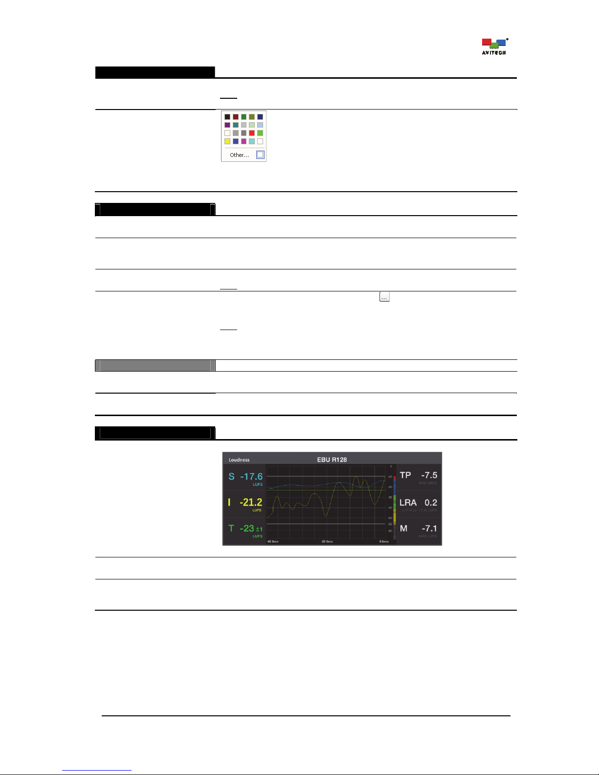
80
Analog Clock #1 / #2
Text
Change the content of the clock’s label text string (default label is “Clock”).
Note
: Currently, the Rainier Summit only supports English, Japanese, Korean,
Chinese (Traditional), and Chinese (Simplified) text string.
Label Font Color
Specify the clock’s label font color. Click Other for more color choices (Standard
tab) or customize the color (Custom tab) by setting the Hue/Saturation/
Luminance as well as the Red/Green/Blue values.
User Logo
Enable
(On / Off)
Allow the display of user logo.
Display
(Foreground /
Background)
Set the user logo to be a part of the image in the window (display in foreground) or
to appear as a background on the image window.
Hide (Full screen mode)
(On / Off)
Allow the display of user logo during full screen mode (default is “On”).
Note
: Only available when Foreground was selected in the previous item Display.
Picture
Upload
Click the cell’s rightmost edge “open” button to select a bitmap file to upload as
user logo (e.g., 1920×1200 image would take approximately 180 seconds or more
depending on the system’s resource allocation).
Note
: To fill the entire screen, size (pixel) of the user logo picture must be the same
as the multiviewer’s output resolution. In case file size is larger than the Rainier
Summit’s output resolution (see Card Parameters
Resolution), the system will
detect and prevent it from displaying as the user logo picture.
Position
X
Y
Specify the location of the user logo appearing on screen by setting the X and Y
coordinates.
Width
Height
Specify the size of the user logo appearing on screen by setting the Width and
Height values.
Loudness
This item only applies for the main board bundled with a loudness card.
Enable
(On / Off)
Allow the display of the loudness monitor.
Loudness Monitor
Hide (Full screen mode)
(On / Off)
Allow the display of the loudness monitor during full screen mode (default is “On”).
Profile
(EBU R128, ATSC A/85,
User defined)
Set the loudness compliance measurement. The EBU R128 or ATSC A/85 Mode is
displayed only when the measurements are compliant with those specifications.
User defined mode allows you to set a specified loudness range measurement.
Page 87
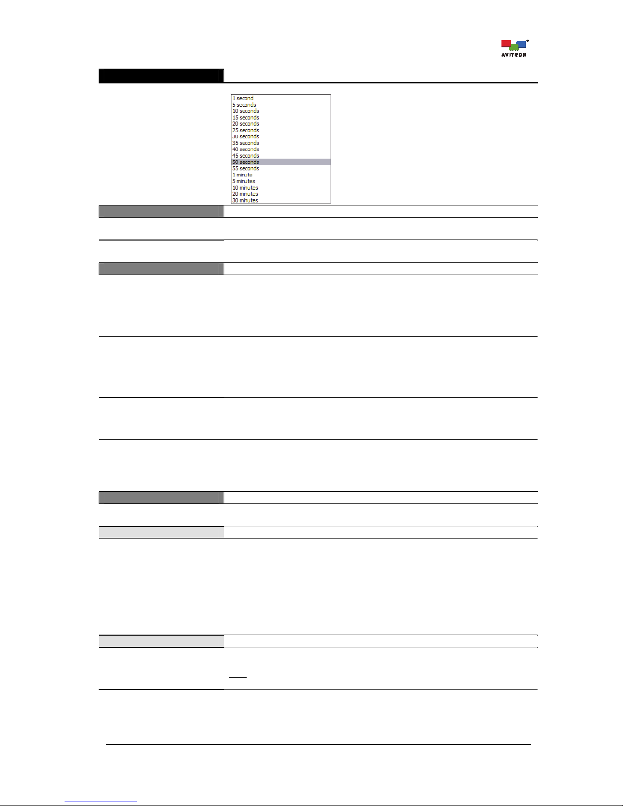
81
Loudness
This item only applies for the main board bundled with a loudness card.
Time Range
Set the horizontal time scale of the loudness monitor to the desired duration.
Size
X
Y
Specify the location of the loudness monitor appearing on screen by setting the X
and Y coordinates.
Width
Height
Specify the size of the loudness monitor appearing on screen by setting the Width
and Height values.
User Defined
Loudness Range
(On / Off)
Allow the display of the loudness range.
Loudness Range (LRA) is a measure of the variation of loudness on a macroscopic
time-scale. Loudness Range or LRA describes the overall program material range:
from the softest to the loudest portion. The range is quantified in LU, and to avoid
extreme events from affecting the overall result, the top 5% and the lowest 10% of
the total loudness range is being excluded from the LRA measurement.
Target
(–60 to –10)
Set the user-defined Target level. This parameter will change the target value in
the loudness monitor.
Target levels are specified in various broadcast standards, but only varies slightly.
For instance, the ATSC A/85 standard recommends a target of –24 and uses the
LKFS term, whereas the EBU R128 standard sets the target level at –23 and uses
the LUFS term.
Relative Gate
(–8 or –10)
Set the user defines Relative Gate.
A gating scheme that pauses measurement when the audio level drops below a
threshold of –10 or –8 LU relative to an un-gated measurement of the same
program material has been developed.
Short Term
(1 to 15)
Set the user-defined Short Term value. Changing this parameter affects the short
term calculation.
Short-term loudness (S) corresponds to loudness using a three second sliding
window with no gating. It is basically equivalent to momentary loudness but with a
long measurement period.
Measurement
Mode
(HDMI OUT / SDI OUT)
Select the audio channels for monitoring to the HDMI OUT or SDI OUT port.
Source
This item is not applicable when HDMI OUT is selected in the previous item Mode.
Channel 1 – Channel 4
( Group 1 CH1/CH2
Group 1 CH3/CH4
Group 2 CH1/CH2
Group 2 CH3/CH4
Group 3 CH1/CH2
Group 3 CH3/CH4
Group 4 CH1/CH2
Group 4 CH3/CH4)
Select the audio meter’s group (embedded audio) of Channel 1 ~ Channel 4.
SDI embedded audio is divided into four groups (CH1 to CH4), any of the 4 Groups
can be assigned to Channel 1/2/3/4.
Monitor
Left
(Group # CH#/CH#)
Select the Left channels of the 5.1 surround sound audio system that you wish to
assign to the HDMI OUT.
Note
: The group and channel shown in the drop-down menu list will depend on the
meter’s group selected in the previous item.
Page 88
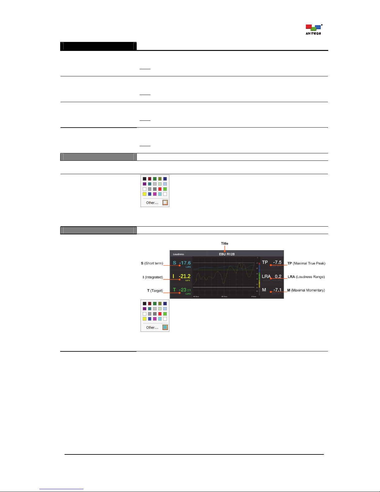
82
Loudness
This item only applies for the main board bundled with a loudness card.
Right
(Group # CH#/CH#)
Select the Right channels of the 5.1 surround sound audio system that you wish to
assign to the HDMI OUT.
Note
: The group and channel shown in the drop-down menu list will depend on the
meter’s group selected in the previous item.
Center
(Group # CH#/CH#)
Select the Center channels of the 5.1 surround sound audio system that you wish
to assign to the HDMI OUT.
Note
: The group and channel shown in the drop-down menu list will depend on the
meter’s group selected in the previous item.
Left Surround
(Group # CH#/CH#)
Select the Left Surround channels of the 5.1 surround sound audio system that
you wish to assign to the HDMI OUT.
Note
: The group and channel shown in the drop-down menu list will depend on the
meter’s group selected in the previous item.
Right Surround
(Group # CH#/CH#)
Select the Right Surround channels of the 5.1 surround sound audio system that
you wish to assign to the HDMI OUT.
Note
: The group and channel shown in the drop-down menu list will depend on the
meter’s group selected in the previous item.
Label
Text
Input the text string appearing on the label of the loudness monitor (up to 32
characters).
Text Color
Specify the loudness monitor’s label font color. Click Other for more color choices
(Standard tab) or customize the color (Custom tab) by setting the Hue/Saturation
/Luminance as well as the Red/Green/Blue values.
Color
Title
S (Short term)
I (Integrated)
T (Target)
TP (Maximal True Peak)
LRA (Loudness Range)
M (Maximal Momentary)
Color setting for loudness monitor’s components.
Specify the loudness monitor component’s color appearance on screen. Click
Other for more color choices (Standard tab) or customize the color (Custom tab)
by setting the Hue/Saturation/Luminance as well as the Red/Green/Blue values.
Page 89
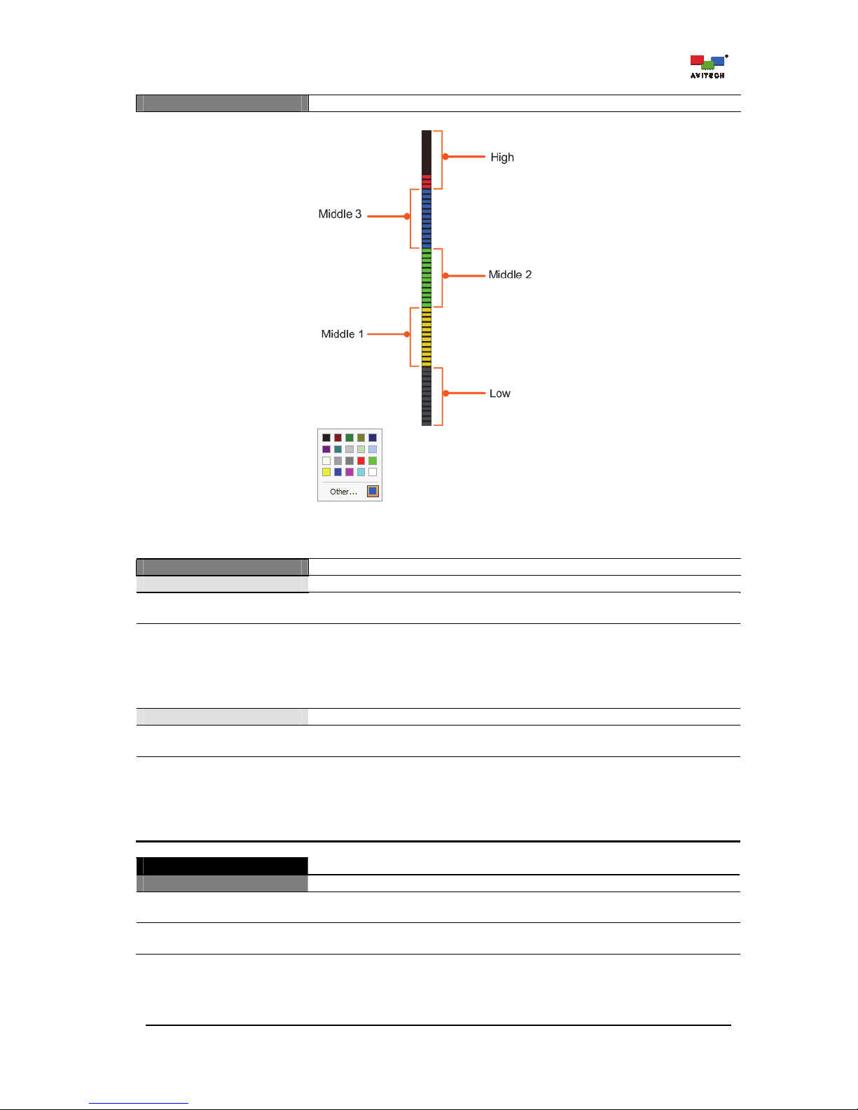
83
Meter
High Light / High Dark
Middle3 Light / Middle3 Dark
Middle2 Light / Middle2 Dark
Middle1 Light / Middle1 Dark
Low Light / Low Dark
Color setting for loudness meter components.
Specify the light and dark color’s degree in the loudness meter appearing on
screen. Click Other for more color choices (Standard tab) or customize the color
(Custom tab) by setting the Hue/Saturation/Luminance as well as the Red/
Green/Blue values.
Alarm
Too Loud
Enable
(On / Off)
Allow the display of the “Volume is too loud” alarm.
Align
(–70 to 0)
Specify the meter’s measurement alignment when the audio is too loud. This
parameter sets the maximum allowable value for the integrated (I) measurement
without triggering an alarm.
For instance, the maximum tolerance is set to –20. If the integrated measurement
is –19, then a “Volume is too loud” alarm will be triggered. If the integrated (I)
measurement is –20, then no alarm will be triggered.
Too Quiet
Enable
(On / Off)
Allow the display of the “Volume is too low” alarm.
Align
(–70 to 0)
Specify the meter’s measurement alignment when the audio is too low (inaudible).
This parameter sets the minimum allowable value for the integrated (I)
measurement without triggering an alarm.
For instance, the maximum tolerance set to –25. If the integrated measurement
is –25, then a “Volume is too quiet” alarm will be triggered. If the integrated
measurement is –26, then no alarm is triggered.
Alert
Alert – Power
Enable
(On / Off)
Turn on the power alert feature that is triggered when either one of the power
source in redundant power supply is cut-off.
Display Preview Test
(On / Off)
Allows the confirmation of the power alert position appearing on screen.
Page 90

84
Alert
Time Lag
(Always on, 1, 5, 10, 30
minutes, 1, 2, 6, 12, 24
hours)
Set the time interval between cut-off of one of the redundant power source and
when power alarm is shown on screen.
Display Time (Seconds)
(1 to 120)
Set the length of time that power alarm remains on screen.
Font Color
Specify the power alert’s font color. Click Other for more color choices (Standard
tab) or customize the color (Custom tab) by setting the Hue/Saturation/
Luminance as well as the Red/Green/Blue values.
Border Color
Change the power alert’s border color.
Position
(X / Y)
Specify the location of the power alert appearing on screen by setting the X and Y
coordinates.
Alert – Fan
Enable
(On / Off)
Turn on the fan alarm feature that is triggered when either one of the power source
from the redundant power supply is cut-off.
Display Preview Test
(On / Off)
Allows you to confirm the fan alert’s position appearing on screen.
Time Lag
(Always on, 1, 5, 10, 30
minutes, 1, 2, 6, 12, 24
hours)
Set the time interval between the occurrence of cut-off of one of the fan module and
when power alarm is shown on screen.
Display Time (Seconds)
(1 to 120)
Set the length of time that fan alert remains on screen.
Font Color
Specify the fan alert’s font color. Click Other for more color choices (Standard tab)
or customize the color (Custom tab) by setting the Hue/Saturation/ Luminance
as well as the Red/Green/Blue values.
Border Color
Change the fan alert’s border color.
Position
(X / Y)
Specify the location of the fan alert appearing on screen by setting the X and Y
coordinates.
Alert – Temperature
Enable
(On / Off)
Turn on the temperature alert feature that is triggered when a card’s operating
temperature is warmer than normal.
Display Preview Test
(On / Off)
Allows you to confirm the temperature alert display position on screen.
Time Lag
(Always on, 1, 5, 10, 30
minutes, 1, 2, 6, 12, 24
hours)
Set the time interval when a card’s operating temperature is not normal and when
the temperature alert is shown on screen.
Page 91

85
Alert
Display Time (Seconds)
(1 to 120)
Set the length of time that a card’s operating temperature alert remains on screen.
Font Color
Specify the temperature alert’s font color. Click Other for more color choices
(Standard tab) or customize the color (Custom tab) by setting the Hue/
Saturation/Luminance as well as the Red/Green/Blue values.
Border Color
Change the temperature alert’s border color.
Position
(X / Y)
Specify the location of the temperature alert appearing on screen by setting the X
and Y coordinates.
Display Label
Enable
(On / Off)
Allow you to show the display label on screen.
Priority
(Top Most / Background)
Set the display label to the top most level over the window (display top most in
foreground) or to appear as a background on the image window.
Hide (Fullscreen mode)
(On / Off)
Allows showing of the display label during full screen mode (default is “Off”).
Position
X
Y
Specify the location of the display label appearing on screen by setting the X and
Y coordinates.
Label: Display 001
Size
(6 – 72 pixel)
Set the size (height) of the display label (default label is “72” pixel).
Font Color
Specify the display label’s font color. Click Other for more color choices
(Standard tab) or customize the color (Custom tab) by setting the Hue/
Saturation/Luminance as well as the Red/Green/Blue values.
B-G Color
Specify the display label’s background color. Click Other for more color choices
(Standard tab) or customize the color (Custom tab) by setting the Hue/
Saturation/Luminance as well as the Red/Green/Blue values.
Text
Change the content of the display label’s text string.
Note
: Currently, the Rainier Summit only supports English, Japanese, Korean,
Chinese (Traditional), Chinese (Simplified) text string.
Border
Border Width
(0 – 6 pixel)
Set the border width for the display label (default border width is “2”).
Page 92

86
Border Color
Change the display label’s border color.
Table 5-1 Phoenix-Q Software: Setting the Chassis and Card Properties for Rainier Summit
The following table shows the Properties setting for each image window in the Rainier Summit.
Figure 5-2 Phoenix-Q Software: Image Properties Window
Page 93

87
Image
Image Enable
(On / Off)
Show or hide the selected window on the monitor. Upon selecting Off, the hidden
window will appear on the Available Windows panel (see below). To display the
window again, simply drag the icon into the main display area (can also drag
multiple windows utilizing the Ctrl key + left mouse button).
Source
(Card 1:1 – BNC01 to Card
6:4 – BNC24)
Select the input signal source for each window (i.e. if Card 2:1 – BNC05 was
selected for a window, the window would be displaying the same input signal from
Card 2, BNC port 1).
No Video Display
(Black / Last Frame)
Select the display format when detecting the absence of video signal (default
display shows a “Black” image on the window).
SDI Level B-DS
(Stream 1 / Stream 2)
Select the 3G-SDI level B dual stream channel to monitor (default is “Stream 1”)
Note:
Dual Stream 3G-SDI is a specific variant of the 3G-SDI signal that combines
two completely separate 4:2:2 image streams into a single SDI signal.
TSL Enable
(On / Off)
Enable/Disable TSL for the configuration of the IP port with a TSL connection.
Alarm Setting
Change . . .
Open up the alarm “Settings” window for configuring alarm detection and display
for each image window.
Video
Freeze Display
(On / Off)
Activate the “video freeze” alarm feature. Freeze detection is done by comparing
successive frames based on the Video Freeze’s parameters (Sensitivity Level,
Period, and Threshold) under the “Image” properties. Once the alarm is triggered,
it will only be released if the freeze condition is no longer detected.
Note
: Analog input signal is not supported.
Black Display
(On / Off)
Activate the “video black” alarm feature. Black detection is done by comparing
successive frames based on the Video Black’s parameters (Video Detect Area,
Level, Threshold, and Detect Number (Frame)) under the Image properties. Once
the alarm is triggered, it will only be released if the black display condition is no
longer detected.
Note
: Analog input signal is not supported.
Display Enable
(On / Off)
Enable/Disable the video alarm display (for video signal loss). The alarm will be
released upon detecting the presence of video signal.
Page 94

88
Video
No Video Lock
(On / Off)
Turning on video alarm lock allows the alarm during occurrence of “NO VIDEO /
VIDEO BLACK / VIDEO FREEZE” to remain on screen even after video image
signal has resumed streaming from the input source. This feature is most useful
when the operator is away and wants to keep track of any occurrence of “video
loss, video black or video freeze.
Note
: To remove the “NO VIDEO” text on screen, click the Erase Alarm button.
Horizontal Position
(Left / Center / Right)
Adjust the position of the video alarm horizontally (default alarm horizontal
position is “Center”).
Vertical Position
(Top / Center / Bottom)
Adjust the position of the video alarm vertically (default alarm vertical position is
“Top”).
Font Color
Specify the video alarm’s font color. Click Other for more color choices (Standard
tab) or customize the color (Custom tab) by setting the Hue/Saturation/
Luminance as well as the Red/Green/Blue values.
B-G Color
Specify the video alarm’s background color. Click Other for more color choices
(Standard tab) or customize the color (Custom tab) by setting the Hue/
Saturation/Luminance as well as the Red/Green/Blue values.
Blending Level
(0 up to 7)
Use the slider to set the transparency level (default is “0” (no transparency)) of the
alarm appearing on screen.
Video Border
Red Color
(On / Off)
Enable the image window’s border to turn Red as warning.
Flash
(On / Off)
Enable the image window’s border to Flash as warning.
Audio
Display Enable
(On / Off)
Enable/Disable audio alarm display (for audio signal loss/high/low/out of phase).
No Audio Lock
(On / Off)
Turning on audio alarm lock allows the alarm during occurrence of “NO AUDIO /
OUT OF PHASE” to remain on screen even after audio signal has resumed
streaming from the input source. This feature is most useful when the operator is
away and wants to keep track of any occurrence of audio loss or out of phase.
Note
: To remove the “NO AUDIO” text on screen click the Erase Alarm button.
No Audio Alarm
(Single Meter)
(On / Off)
Activate the alarm that is triggered when no audio is detected.
Horizontal Position
(Left / Center / Right)
Adjust the position of the audio alarm horizontally (default alarm horizontal position
is “Center”).
Vertical Position
(Top / Center / Bottom)
Adjust the position of the audio alarm vertically (default alarm vertical position is
“Center”).
Page 95

89
Audio
Font Color
Specify the audio alarm’s font color. Click Other for more color choices (Standard
tab) or customize the color (Custom tab) by setting the Hue/Saturation/
Luminance as well as the Red/Green/Blue values.
B-G Color
Specify the audio alarm’s background color. Click Other for more color choices
(Standard tab) or customize the color (Custom tab) by setting the Hue/
Saturation/Luminance as well as the Red/Green/Blue values.
Blending Level
(0 up to 7)
Use the slider to set the transparency level (default is “0” (no transparency)) of the
alarm appearing on screen.
Video Border
Red Color
(On / Off)
Enable the image window’s border to turn Red as warning.
Flash
(On / Off)
Enable the image window’s border to Flash as warning.
Response Time
Signal In
(0.25 to 49.75)
Set the Signal In alarm response time for audio alarm to react upon regaining the
audio signal (audio signal status from “abnormal” to “normal”).
Signal Out
(0.25 to 49.75)
Set the Signal Out alarm response time for audio alarm to react upon losing the
audio signal (audio signal status from “normal” to “abnormal”).
C.C
C.C Detect
(On / Off)
Allow detection of closed captioning. “No C.C” would be displayed if detection is
enabled but input signal is without closed captioning.
Mode
(Auto Sense / C.C 608 /
C.C 708)
Allow to show the type of closed captioning. Upon selecting Auto Sense, the Rainier
Summit will automatically detect ancillary packets (DID/SDID) located in the vertical
blanking region of the input source. Alternatively, select C.C 608 or C.C 708 for
closed captioning services defined in their respective standards.
Horizontal Position
(Left / Center / Right)
Adjust the position of the C.C alarm horizontally (default alarm horizontal position is
“Right”).
Vertical Position
(Top / Center / Bottom)
Adjust the position of the C.C alarm vertically (default alarm vertical position is
“Bottom”).
Font Color
Specify the C.C alarm’s font color. Click Other for more color choices (Standard
tab) or customize the color (Custom tab) by setting the Hue/Saturation/
Luminance as well as the Red/Green/Blue values.
B-G Color
Specify the C.C alarm’s background color. Click Other for more color choices
(Standard tab) or customize the color (Custom tab) by setting the Hue/
Saturation/Luminance as well as the Red/Green/Blue values.
Blending Level
(0 up to 7)
Use the slider to set the transparency (default is “0” (no transparency)) of the label
appearing on screen.
Page 96
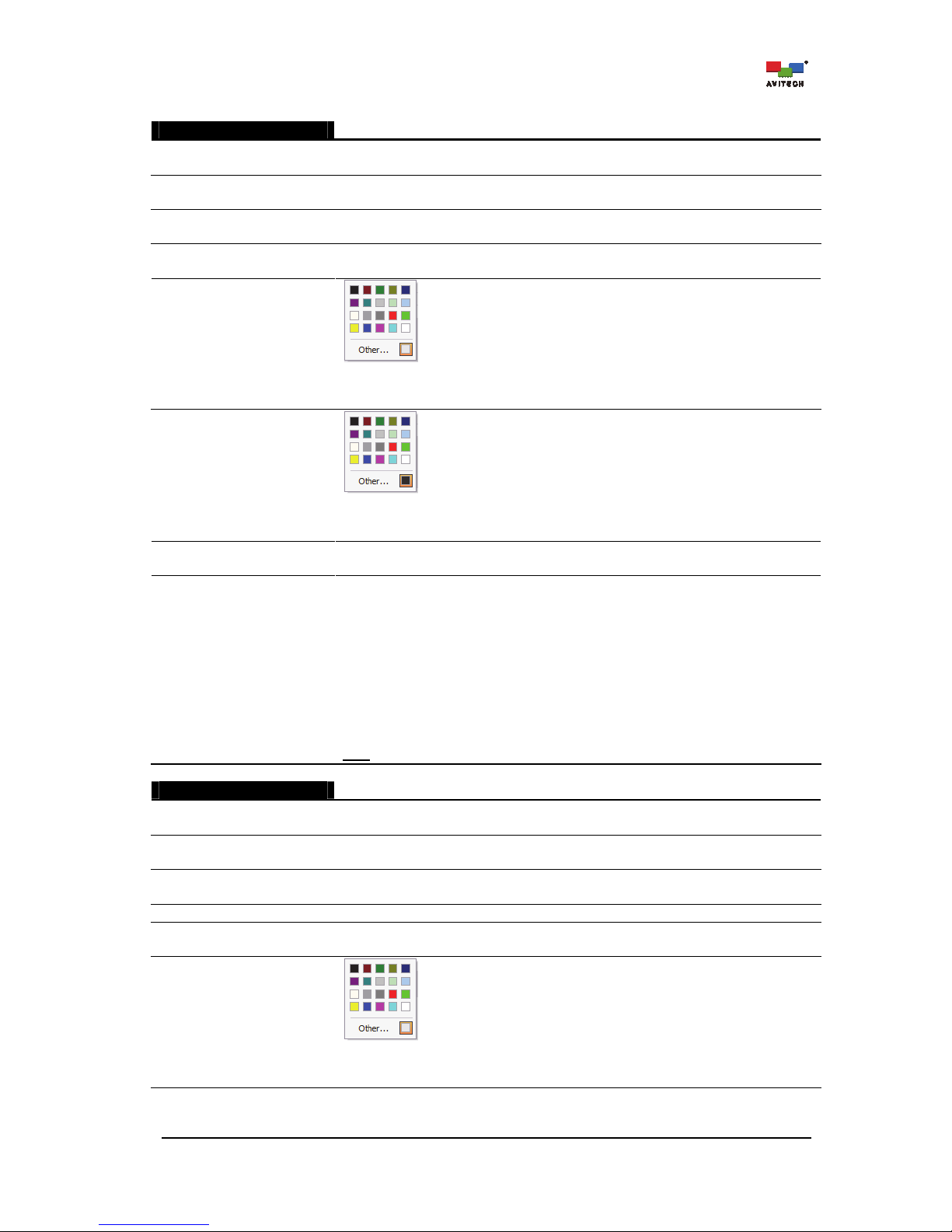
90
Signal Format
Enable
(On / Off)
Enable/Disable the display of input video signal format for each image window.
Horizontal Position
(Left / Center / Right)
Adjust the position of the signal format horizontally (default alarm horizontal position
is “Left”).
Vertical Position
(Top / Center / Bottom)
Adjust the position of the signal format vertically (default alarm vertical position is
“Top”).
Font Size
(6 to 72)
Set the size (height) of the signal format (default font size is “20” pixel).
Font Color
Specify the signal format’s font color. Click Other for more color choices (Standard
tab) or customize the color (Custom tab) by setting the Hue/
Saturation/Luminance as well as the Red/Green/Blue values.
B-G Color
Specify the signal format’s background color. Click Other for more color choices
(Standard tab) or customize the color (Custom tab) by setting the Hue/
Saturation/Luminance as well as the Red/Green/Blue values.
Blending Level
(0 up to 7)
Use the slider to set the transparency level (default is “0” (no transparency)) of the
signal format appearing on screen.
Display AFD
(On / Off)
On: Display the AFD (Active Format Description). Standard AFD (active format
description) codes provide information about where in the coded picture the active
video is and also the "protected area" (area that needs to be shown). Outside of the
protected area, edges at the sides or the top/bottom can be removed without
missing anything significant. The Rainier Summit can then use this information,
together with knowledge of the display shape and user preferences, to choose a
presentation mode.
Active area signaling allows the display device to process the incoming signal to
provide the highest resolution and most accurate picture possible. While aspect
ratio signaling allows the display device to produce the best image possible
.
Off: Disable the AFD display feature.
Note
: This item is only available when selecting On for Signal Format.
Timecode
Enable
(On / Off)
Enable/Disable timecode display (form of media metadata).
Horizontal Position
(Left / Center / Right)
Adjust the position of the timecode horizontally (default alarm horizontal position is
“Center”).
Vertical Position
(Top / Center / Bottom)
Adjust the position of the timecode vertically (default alarm vertical position is
“Bottom”).
Background
Display the timecode’s background.
Font Size
(6 to 72)
Set the size (height) of the timecode (default font size is “20” pixels).
Font Color
Specify the timecode’s font color. Click Other for more color choices (Standard tab)
or customize the color (Custom tab) by setting the Hue/Saturation/ Luminance as
well as the Red/Green/Blue values.
Page 97
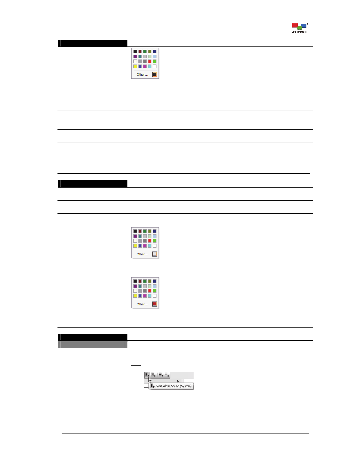
91
Timecode
B-G Color
Specify the timecode’s background color. Click Other for more color choices
(Standard tab) or customize the color (Custom tab) by setting the Hue/
Saturation/Luminance as well as the Red/Green/Blue values.
Blending Level
(0 up to 7)
Use the slider to set the transparency (default is “3”) of the timecode appearing on
screen.
Mode
(LTC / VITC #1 /
VITC #2)
Select the input source of the timecode to be displayed on a window when the input
source is HD-SDI.
Note
: This item is not available upon selecting On in DVITC.
DVITC
(On / Off)
Enable/Disable timecode display for DVITC.
Line Number (10 ~ 20)
Specify the DVITC inserted in an active line for extraction of a SD-SDI input source.
For 525-line/60-field systems, the DVITC shall be inserted on lines 12 and 275.
Insertion on lines 14 and 277 is optional.
For 625-line/50-field systems, the DVITC shall be inserted on lines 19 and 332.
Insertion on lines 21 and 334 is optional. Default: Line 19 for SD-625.
Timecode Loss
Enable
(On / Off)
Enable/Disable display of timecode loss alarm for each image window.
Horizontal Position
(Left / Center / Right)
Adjust the position of the timecode loss alarm horizontally (default alarm horizontal
position is “Center”).
Vertical Position
(Top / Center / Bottom)
Adjust the position of the timecode loss alarm vertically (default alarm vertical
position is “Bottom”).
Font Color
Specify the timecode loss’ font color. Click Other for more color choices (Standard
tab) or customize the color (Custom tab) by setting the Hue/
Saturation/Luminance as well as the Red/Green/Blue values.
B-G Color
Specify the timecode loss’s background color. Click Other for more color choices
(Standard tab) or customize the color (Custom tab) by setting the Hue/
Saturation/Luminance as well as the Red/Green/Blue values.
Alarm Sound
Video
Enable
(On / Off)
Activate playback of alarm sound when no video/video black/freeze is detected in a
window.
Note
: To enable alarm sound playback, click the Start Alarm Sound (System) icon
(will become grayed-out).
Page 98
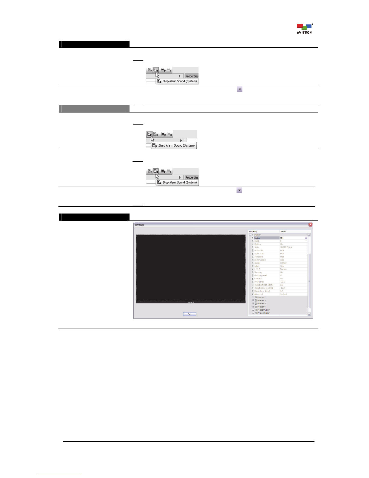
92
Alarm Sound
Set Playback Duration
(Second)
Set “video alarm” sound playback duration (seconds) for a window.
Note
: To shut off alarm sound playback before the specified time set has elapsed,
click the Start Alarm Sound (System) icon (will become grayed-out).
File
Click the cell’s rightmost edge “change” button to select the audio file as the
video alarm sound for the window.
Note
: Only the “WAV” audio file format is supported.
Audio
Enable
(On / Off)
Activate playback of alarm sound when no audio is detected in a window.
Note
: To enable alarm sound playback, click the Start Alarm Sound (System) icon
(will become grayed-out).
Set Playback Duration
(Second)
Set “audio alarm” sound playback duration (seconds) for a specific window.
Note
: To shut off alarm sound playback before the specified time duration has
elapsed, click the Start Alarm Sound (System) icon (will become grayed-out).
File
Click the cell’s rightmost edge “change” button to select the audio file as the
audio alarm sound for the window.
Note
: Only the “WAV” audio file format is supported.
Meter Layout
Status: On / Off
Change . . .
Specify the audio meter layout for the particular window to monitor on screen.
Page 99
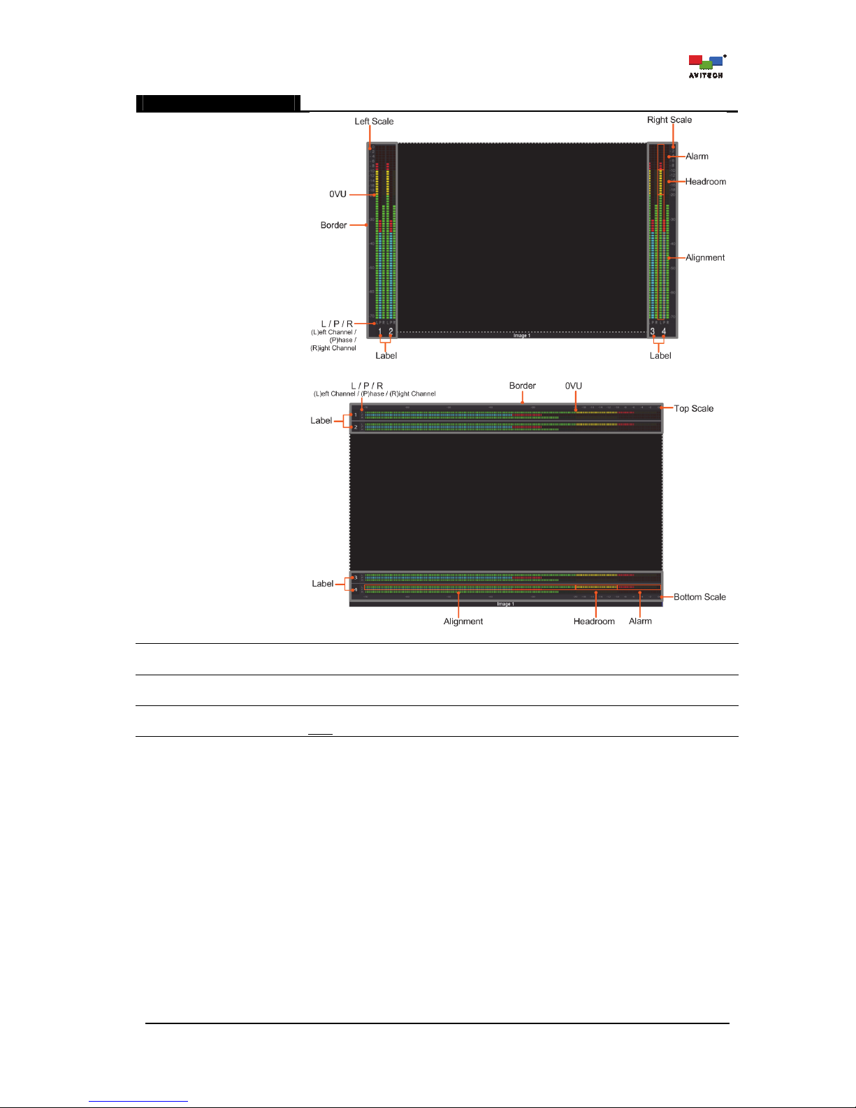
93
Meter Layout
Meter layout vertically positioned.
Meter layout horizontally positioned.
Enable
(On / Off)
Enable/Disable audio meter display for each image window.
Width
(4 to 16)
Specify the audio meter’s width.(range from “4” to “16” pixels per channel)
Outside
(On / Off)
Allow the location of the audio meter to be outside the video area.
Note
: This is not allowed when the image width is less than 128 pixels.
Page 100
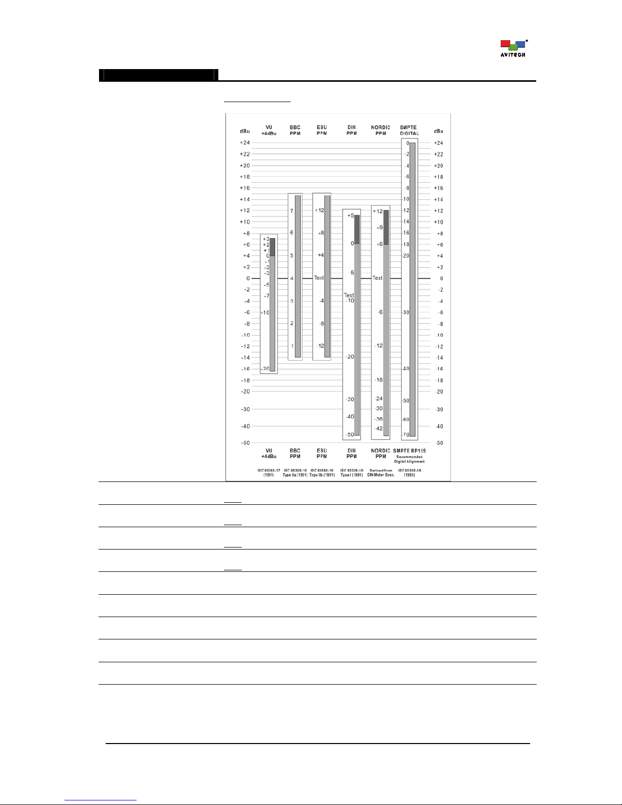
94
Meter Layout
Scale
Allow the selection of the type of meter scale.
Audio meter scale
: SMPTE Digital / VU / BBC PPM / EBU PPM / DIN PPM / Nordic
PPM
Left Scale
(Display / Hide)
Display/Hide the scale of the meter when located at the left of a window.
Note
: This is not allowed when the Position is Horizontal.
Right Scale
(Display / Hide)
Display/Hide the scale of the meter when located at the right of a window.
Note
: This is not allowed when the Position is Horizontal.
Top Scale
(Display / Hide)
Display/Hide the scale of the meter when located at the top of a window.
Note
: This is not allowed when the Position is Vertical.
Bottom Scale
(Display / Hide)
Display/Hide the scale of the meter when located at the bottom of a window.
Note
: This is not allowed when the Position is Vertical.
Border
(Display / Hide)
Display/Hide the border of the meter.
Label
(Display / Hide)
Display/Hide the label of the meter.
L / P / R
(Display / Hide)
Display/Hide the Left channel/Phase/Right channel meter.
Blending
(On / Off)
Allow meter blending with video.
Blending Level
(0 up to 7)
Use the slider to set the transparency (default is “0” (no transparency)) of the meter
appearing on screen.
 Loading...