

Page 1

GSM-EDGE Repeaters
PRODUCT DESCRIPTION AND USER'S MANUAL
4.2 Install the Repeater
Instructions in the left column are fast track instructions and can be used by experienced users. Other users
are recommended to read the complete text in this installation guide
4.2.1 Unpack the Repeater
Unpack the
repeater
Inspect the shipped material before unpacking the equipment, document any visual
damage and report according to routines.
A delivery of a repeater from Avitec contains:
! Checklist with delivered items
! Repeater
! Wall mounting kit or rack mounting kit (defined in order)
! 4 bolts for attaching repeater to mounting kit
! Cable cover
! Keys to repeater and cable cover
! CD containing Product Description and User’s Manual
! Any other specifically ordered item
4.2.2 Mount the Repeater
Mount the
repeater on a wall,
on a pole or in a
rack
Ensure proper
ventilation
Mount the repeater in an accessible location and in a location that fulfils the
environmental requirements.
The repeater can be mounted on the wall, on a pole or in a 19 inch rack. The
Repeater is delivered with a wall mounting kit or a rack mounting kit.
The repeater needs to be mounted tightly to eliminate vibrations
Wall mounting kit Rack mounting kit
Mount the repeater so that heat can be dispersed from it. The repeater wall mounting
kit ensures an optimum airflow between the wall and the repeater itself. Do not
block this air channel as it will cause the MTBF of the repeater to drop dramatically,
or even in the worst case cause the repeater to fail completely.
If possible use a wall in the shadow to minimize the overall sun loading. If sufficient
shielding cannot be obtained, an additional sun shield should be mounted.
© Avitec AB A1009300 A 104 (177)
Page 2

GSM-EDGE Repeaters
PRODUCT DESCRIPTION AND USER'S MANUAL
Example of a sun shield
4.2.3 Ensure Proper Grounding
Connect the
grounding
protection
Ensure that good grounding protection measures are taken to create a
reliable repeater site. Make sure to use adequately dimensioned
grounding cables. The minimum recommended conductive area for a
grounding cable is 16mm
The antenna cabling should be connected to ground every 10m by a
reliable grounding kit.
Make sure the grounding product used is suitable for the kind and size
of cable being used.
Connect the repeater box bolt to the same ground.
2.
Ground
Ground connector on repeater
© Avitec AB A1009300 A 105 (177)
Page 3

GSM-EDGE Repeaters
PRODUCT DESCRIPTION AND USER'S MANUAL
4.2.4 Ensure Good EMV Protection (Lightning)
Caution
If insufficient Electro magnetic Protection is provided,
or if EMV measures are not taken, warranties issued by Avitec are not valid.
Connect the
lightning
protection
The lightning hazard to electric and electronic equipment consists in the
interferences of direct lightning current infections and high surge voltages induced
by the electromagnetic field of nearby lightning channels or down conductors.
Amplitudes from cloud-to-earth lightning amounts to several 10kA and may last
longer than 2 ms. The damage caused depends on the energy involved and on the
sensitivity of the electronics systems.
Ensure that lightning protection measures are taken to create a reliable repeater site.
Protect all coaxial cables and power cables from the transients caused by lightning.
Fit all cables with suitable lightning protection devices.
For detailed information please refer to IEC 61024-1 and 61312-1 for international
standards for protection of information systems against LEMP, Lightning
Electromagnetic Pulse, including radio transmitters. They define proper planning,
installation and inspection of effective lightni ng protection systems.
The top of the mast
must be higher than
the antennas and be
properly grounded
Antennas
The grounding
path must have
reliable continuity
and be correctly
dimensioned
Primary Protective Devices
Equipotential
Grounding Bars
Repeater
Secondary Protective
Devices
Protective Device
The Avitec repeaters comply with the EN standard ETS 301 498-8 which stipulates
demands on lightning/surge protection for typical infrastructure telecom equipment
installations.
Several lightning protection devices should be used in series with declining
threshold voltages to help attenuate the pulse component which makes it through the
first layer of protection.
The primary protective device is part of the site installation and is not supplied by
Avitec. Coaxial lightning protection is normally one of these three types: Gas
230V AC/48V DC
capsule, High-pass and Bandpass.
© Avitec AB A1009300 A 106 (177)
Page 4

GSM-EDGE Repeaters
PRODUCT DESCRIPTION AND USER'S MANUAL
There also need to be a protective device installed on the power supply cord.
Protective device installed in connection with the power supply
4.2.5 Attach Antenna Cables
Note!
Note!
Attach the antenna
cables to the
repeater antenna
connections
For Frequency Translating Repeaters see also 4.2.8 Mount the Coupler
For site installation advice and descriptions of antenna installation see 4.1 Prepare
the Site.
Connectors
The connector to the directional coupler (frequency translating repeaters donor unit)
is N-type female. Antenna connections are DIN 7/16” connectors, female.
Compatibility
Make sure that cables and connectors are compatible. Using cables and connectors
from the same manufacturer is helpful.
Waterproof all
outdoor
connections
Connectors
All connectors must be clean and dry
Waterproof all outdoor connections using silicone, vulcanizable tape or other
suitable substance as moisture and dust can impair RF characteristics.
Make sure enough room has been allocated for the bending radius of the cable. RF
cables must not be kinked, cut or damaged in any way
Connect the RF cables to the antennas tightly but without damaging threads
Fasten cables tight to cable ladder or aluminum sheet
Cable Dimensions
For short length of feeder cables use ½ “, for longer feeder cables use 7/8”. Chose
thicker coax cables for lower attenuation. Minimize the length of the coax cables to
reduce the attenuation
Jumper Cables
Use jumper cables for easy installation. The RF Coaxial cable can be substituted at
each end with a jumper cable.
© Avitec AB A1009300 A 107 (177)
Page 5

GSM-EDGE Repeaters
PRODUCT DESCRIPTION AND USER'S MANUAL
4.2.6 Attach Fiber Cable
Caution
Un-terminated optical receptacles may emit laser radiation.
Do not stare into beam or view with optical instruments.
4.2.6.1 Fiber Connector in the Repeater Casing
Select fibre
Connect the fiber
cable
4.2.6.2 Fiber Connector in the Opto Module
Select fibre
Insert the fiber
into the repeater
via the fitting
Attach the fiber to
the connector in
the Opto Module
Recommended fiber cable is single mode 9/125.
Connect the fibre directly to the FC/APC connector in the casing.
Note! Clean the fiber connector before it is connected to the Opto module, see
instruction below.
Note! This installation is only suitable for indoor use. The IP 65 classification of the
repeater casing is no longer valid.
Recommended fiber cable is single mode 9/125.
The casing of the repeater is equipped with a Pg connector for attachment of a
corrugated hose (NW 17 mm, outer diameter 21.2 mm).
The hose, together with the Pg connector, meet the protection standard IP50.
Supplemented by O-rings, the protection standard IP67 is met.
Make sure the fiber is not too sharply bent. Put the excess fiber cable in soft bends
in the repeater. See illustration. Fasten the cable to make sure it is not damaged
when the repeater lid is closed.
Note! Clean the fiber connector before it is connected to the Opto module, see
instruction below.
© Avitec AB A1009300 A 108 (177)
Page 6

GSM-EDGE Repeaters
PRODUCT DESCRIPTION AND USER'S MANUAL
Make necessary
measurements
Mount the hose to
the connector
Seal the hose Seal the hose according to the demands at hand. If the IP classification of the casing
Make necessary measurements to ensure a correct installation.
When the cable has been installed, the quality of the optical path should be checked
for optical path loss and magnitude and location of any reflections. This can be done
with an Optical Time Domain Reflectometer (OTDR). The total return loss should
be > 45 dB.
Optical reflections can degrade the noise and linearity of a fiber optic link. In
particular, reflections that reach the laser can be a problem. Keep all discrete
reflections to > 60 dB. The FC/APC connectors are polished to a return loss >60 dB.
The casing of the repeater is equipped with a Pg connector for attachment of a
corrugated hose (NW 17 mm, outer diameter 21.2 mm). The hose, together with the
Pg connector, meet the protection standard IP50. Supplemented by O-rings, the
protection standard IP67 is met.
should be maintained O-rings should be used and both ends of the hose should be
sealed with for instance silicon (free of acetic acid).
If necessary to access the
repeater end of the hose,
the power plinth can be
loosened (two screws) and
moved forward.
The repeater seen from the
inside with the conduit
marked by an arrow.
(No fiber is present in this
illustration)
Cleaning Optical Connectors
Optical reflections from a discontinuity such as a poor connector interface appear on an RF spectrum
analyzer trace as stable variations in the noise floor amplitude that are periodic with RF frequency. If the
reflection is bad enough, it could impact the system performance. By far, the most common cause for a large
discrete reflection is a dirty optical connector. A bit of dust or oil from a finger can easily interfere with, or
block this light. Fortunately, it is very easy to clean the connector.
© Avitec AB A1009300 A 109 (177)
Page 7

GSM-EDGE Repeaters
PRODUCT DESCRIPTION AND USER'S MANUAL
Be sure to use the correct procedure for the given connector. When disconnected, cap the FC/APC connector
to keep it clean and prevent scratching the tip of the ferrule.
Alternative 1
Swipe the tip of the ferule 2-3 times with a cotton
swab soaked in alcohol. Let it air dry.
Alternative 2
Use a product specially designed for the purpose.
4.2.7 Supply Power to the Repeater
Caution!
The antenna cables must be connected to the repeater before mains power is switched on. Alternatively the
antenna connections on the repeater can be terminated with 50ohm termination plugs.
Note!
Connect the
repeater to the
power supply
Avitec repeaters can be fed by 110/230 VAC, 50/60 Hz or 48 VDC. Ensure that the
right voltage is used.
Mains power is connected to the repeater via a plinth inside the repeater.
The strain relief fitting is a Pg 13.5 suitable for a 6-12 mm cable diameter.
230VAC or 110 VAC
Connect the power cable to the plinth with the phase linked to the brown cable,
neutral linked to the blue and ground to the yellow/green. See illustration below.
Phase
Neutral
Ground
L
N
Strain Relief Fitting
Connection Plinth
48 VDC
Connect the power cable to the plinth with negative (-48V) to the uppermost
connection and positive (0V) to the middle connection. Leave the lower connection
© Avitec AB A1009300 A 110 (177)
Page 8

GSM-EDGE Repeaters
PRODUCT DESCRIPTION AND USER'S MANUAL
empty. See illustration below.
Negative
Positive
-48V
0V
Strain Relief Fitting
Connection Plinth
Recommended cable areas for 48VDC
0 - 10 meters between repeater and
power supply
10 – 50 meters between repeater and
power supply
Over 50 meters between repeater and
power supply
2,5 mm²
4 mm²
Recommendation is to reconfigure the
installation, or to make special
arrangements to increase cable area
Note!
Back-up battery
Requirements on 48 V power supply
The 48V power supply must comply with SELV requirements, as defined in
EN60950, which implies double isolation. The output power needs to be 48VDC
+25%/-15%.
For a 2 channel repeater the maximum input current is 8A, for a 4-channel repeater
16A.
In 4-channel repeaters there are two power supplies – one in each part of the box.
Each power supply has its own power switch. Both need to be switched on.
Backup Battery
There is a back-up battery installed in connection with the power supply. If there is a
power failure the battery will supply enough power for the Control Module in the
repeater to send information about the power failure.
The backup battery can be switched on an off separately. The switch is placed
adjacent to the mains power switch on the power supply.
In 4-channel repeaters there is a backup battery only in connection to the main
power supply unit.
At delivery the back-up battery is connected. It can be replaced by lifting the battery
pack out of the crate and disconnecting the cable.
© Avitec AB A1009300 A 111 (177)
Page 9

GSM-EDGE Repeaters
PRODUCT DESCRIPTION AND USER'S MANUAL
Connector
4.2.8 Mount the Coupler
Caution!
When the coupler is connected the affected base station sector needs to be taken out of service. Turn the base
station off before detaching the cable to the base station cell antenna. It might shut down the whole network –
chose an off-peak time for this installation.
Note!
Mount the coupler
The Coupler is used only in connection with Frequency Translating Repeaters
The connection between the donor unit and the BTS is made using an Avi tec
Coupler. The attenuation from the BTS to the repeater is -30 dB. The attenuation
through the coupler from the BTS to the antenna is minimal.
Avitec Coupler
The coupler is connected in series with the BTS antenna. J1 and J2 are used for the
connection of the coupler in-between the BTS and the cable to the BTS antenna.
© Avitec AB A1009300 A 112 (177)
Page 10

GSM-EDGE Repeaters
PRODUCT DESCRIPTION AND USER'S MANUAL
To Antenna
Link Ante nna
RF Coaxial cable
Repeater
7/16 type connector, female
Cap
-30dB Coupler
7/16 type
connector
BTS
N-type
connector, female
7/16 type
connector
N-type connector, female
Coupler connections
J3 or J4 is connected to the repeater donor unit depending on the orientation of the
coupler. If J1 is connected to the BTS; J3 is used for connection with the repeater, if
J2 is connected to the BTS; J4 is used for connection with the repeater. The
connector not used (J3 or J4) must be sealed with a cap to prevent the ingression of
dust and water.
! J1 and J2 are DIN 7/16 connectors, one male and one female
! J3 and J4 are N-type connectors, female
1. Disconnect the antenna from the base station
2. Decide whether to connect a filter in series with the antenna cable (between the
coupler and the antenna) to prevent any disturbances from the repeater to reach
the antenna
3. Attach the coupler in-between the base station and the antenna cable. (J1 and
J2).
4. Attach the coupler connector closest to the base station to the repeater donor
antenna connector
5. Attach a cap to the connector closest to the antenna connection
6. Turn the base station back on and verify that it is operational.
7. Seal the coupler with rubber tape. Start on the base station antenna cable and
wrap to the base station port cable. Wrap in a circular motion downwards.
Cover the coupler and its connecting parts completely. This will provide a
weather resistant seal. Complete by adding three layers of PVC tape for UV
protection.
© Avitec AB A1009300 A 113 (177)
Page 11

GSM-EDGE Repeaters
PRODUCT DESCRIPTION AND USER'S MANUAL
4.2.9 Connect External Alarms
Connect external
alarms
If the repeater is equipped with an external alarm interface card the connector plinth
for the external alarms is located at the bottom of the repeater.
The strain relief fitting in is a Pg 13.5 suitable for a 6-12 mm cable diameter.
Connect the alarm cords to the plinth according to the pin layout below (in the
standard version pins 14 – 18 are not used).
Pin # Signal
1 External alarm 1A
2 External alarm 1B
3 External alarm 2A
4 External alarm 2B
5 External alarm 3A
6 External alarm 3B
7 External alarm 4A
8 External alarm 4B
9 Alarm +15V
10 Alarm 0V
11 Relay A
12 Relay B
13 GND
14 NC
15 NC
16 NC
17 NC
18 NC
External Alarm
Four external alarm sources can be connected to the repeater. These alarms operate on
a voltage between 12 and 24VDC. The presence or absence of this voltage will trigger
the alarm depending on how the alarm polarity has been configured via software.
The alarms can be configured active-low or active-high, so that the alarm is given
either in the presence or absence of applied power. Active high means that an applied
voltage of between 12 and 24 V will cause the external alarm indicator to turn red.
Active low means that when there is no voltage the alarm indicator will turn red.
The repeater can supply +15 VDC to an external alarm source through pin 9 and 10.
The maximum allowed load is 50mA.
The repeater contains a relay (pin 11 and 12) that can be connected to an external
device to indicate an alarm. The relay can be configured to trigger on any number of
internal and external alarms. The maximum current that can be supplied is 50mA.
For configuration of external alarms see section 4.4.4 Alarm Configuration.
4.2.10 Close Repeater
Close repeater Close lid and lock repeater, or continue with the next section: Start-up the Repeater
© Avitec AB A1009300 A 114 (177)
Page 12

GSM-EDGE Repeaters
PRODUCT DESCRIPTION AND USER'S MANUAL
4.3 Start-up the Repeater
Caution!
Make sure the antenna cables or 50 ohm terminations are connected to the repeater’s antenna connectors
before the repeater is turned on.
Install the RMC Install the RMC software on a computer from a CD or a diskette.
Connect to the LMT
port
Switch the repeater
on
Open the repeater and connect the computer to the LMT port via a DB9 male
connector with serial RS232 interface.
LMT port
The communication parameters are set automatically by the RMC.
Switch the repeater on by using the power switches on the power supply.
Note! See caution above!
Power switches
There are two switches. One is for the battery and one is for the mains.
Note! Always switch on both switches when the repeater should be switched on.
Note!
Note!
Check power supply
LEDs
© Avitec AB A1009300 A 115 (177)
The power switch has two positions; “on” and “stand by”. In the stand by position
the repeater is still connected to the mains power but not operational.
On 4-channel models both mains power supplies need to be switched on.
Power Supply LED
Check the LEDs on the Power unit and Control Module to ensure that normal
operation conditions have been attained.
The power supply has 4 LEDs to indicate the status.
Mains
Power
+6V +15V +28V
Page 13

GSM-EDGE Repeaters
PRODUCT DESCRIPTION AND USER'S MANUAL
LED 1: Mains Power, green
Slow flash Power supply unit operating on AC or DC
OFF Power supply unit not oper ating
LED 2: +6V, red
Slow flash (every 10 seconds) +6V power supply operating
Quick flash +6V power supply not operating or
operating with malfunction
LED 3: +15V, red
Slow flash (every 10 seconds) +15V power supply operating
Quick flash +15V power supply not operating or
operating with malfunction
LED 4: +28V, red
Slow flash (every 10 seconds) +28V power supply operating
Quick flash +28V power supply not operating or
operating with malfunction
Examples
Mains
Power
Mains
Power
Mains
Power
+6V +15V +28V
+6V +15V +28V
+6V +15V +28V
LED 1 is flashing slowly, LED 2 – 4 are
flashing slowly (once every 10 seconds)
=> power supply unit is operating without
problem
LED 1 is flashing slowly, one or two of
the red LEDs are flashing quickly
=> Mains power is operating but there is a
problem with some of the other voltages
LED 1 is flashing slowly, all of the red
LEDs are flashing quic kly
=> Mains power is out and unit is
operating on backup battery
© Avitec AB A1009300 A 116 (177)
Page 14

GSM-EDGE Repeaters
PRODUCT DESCRIPTION AND USER'S MANUAL
Check Control
Module LEDs
Control Module LED
The Control Module has 3 LEDs to indicate the status.
123
LED 1: green
OFF GSM Module switched OFF
Permanent ON GSM Module Switched on, not registered on network
Slow Flash GSM Module switched on, registered on network
(approximately 1 flash per second)
Quick flash Module switched on, registered on network, call
active (approximately 3 flashes per second)
LED 2: red
OFF Control Module switched OFF
Slow Flash Control Module switched on, status OK (once every
10 seconds)
Quick flash Control Module switched on, one or more errors /
alarms detected (except door status)
Check optic module
LEDs.
LED 3: blue
OFF Control Module switched OFF, or no one logged in
Slow Flash Control Module switched on, nobody logged in
locally OK (once every 10 seconds)
Quick flas h Control Module switche d on, someone logged in
remotely or locally
Opto Module LED
On the optic module there are 4 green LEDs.
TEMP Local temperature in opto
module
POWER Power to unit green light = power on
OPTO TX Transmitted signal on fiber green light = OK
OPTO RX Received signal on fiber green light = OK
green light = OK
© Avitec AB A1009300 A 117 (177)
Page 15

GSM-EDGE Repeaters
PRODUCT DESCRIPTION AND USER'S MANUAL
Start the RMC The RMC can be started from the Start menu (or by clicking on the RMC icon, if
made available).
Select “Cable”
connection
Select
communication port
Enter user name and
password
These are the default settings:
User Name Password Authority
USERNAM1 PASSWRD1 read/write
USERNAM2 PASSWRD2 read/write
USERNAM3 PASSWRD3 read only
USERNAM4 PASSWRD4 read only
The system does not differentiate between upper and lower case letters.
Note!
Note!
Do not use the number pad when entering numbers.
Failed login attempts are logged. Default maximum number is 8. It is
decremented by one every hour, which means that it takes one hour after the last
failed attempt before a new try can be made.
4.3.1 Choose Work View
Choose “Console”
mode, “Terminal”
mode or “Firmware”
mode
© Avitec AB A1009300 A 118 (177)
Page 16

GSM-EDGE Repeaters
PRODUCT DESCRIPTION AND USER'S MANUAL
Console mode
The console mode displays a large number of repeater parameters and contains
a number of console pages. It adjusts its user interface to adapt to the features of
the connected repeater.
Terminal mode
Firmware mode
The terminal mode is used for communication with the repeater using its native
command line interface. This interface follows the VT100 standard. For some
special actions and error tracing, this mode gives an enhanced availability of the
repeater.
The firmware mode is used for monitoring the currently installed software and
for uploading new software to the repeater.
© Avitec AB A1009300 A 119 (177)
Page 17

GSM-EDGE Repeaters
PRODUCT DESCRIPTION AND USER'S MANUAL
4.4 Configure the Repeater
The following pages will guide you through the configuration of Channel Selective repeaters as well as
Frequency Translating repeaters utilizing the Repeater Maintenance Console (RMC) so ft ware.
Configuration of a repeater is made partially on site and partially remotely through the AEM. At site the RF
parameters are set and verified, the repeater is given a name (a tag) and the remote communication is set and
verified. All other configuration can, and should be made from the AEM.
4.4.1 Set up RF Configuration
4.4.1.1 Channel Selective Re peaters
Ensure online
communication with
the repeater
This image will
appear
Chain 1
Channel number
Uplink
Attenuation
Power level
Downlink
Attenuation
Power level
Select “Console” mode
Select “RF/Status” window
23
30 30
OFF
45
30
OFF
3030
OFFOFF
--
dBm
Saturation level
Set all power levels
Set “Power Level” in uplink and downlink to “OFF” in all chains
to “OFF”
In the “Power Level” menu the output power can be limited to a specific value or the
output power can be switched off completely by choosing “OFF”.
Set all attenuation
levels to a maximum
Set “Attenuation” to the maximum value in both chains uplink and downlink
(In a 4 channel repeater there are 4 chains).
© Avitec AB A1009300 A 120 (177)
Page 18

GSM-EDGE Repeaters
PRODUCT DESCRIPTION AND USER'S MANUAL
Choose the maximum attenuation value from the drop down menu, in this case 30dB.
Set channel numbers
Monitor the input
power
Configure the
downlink of Chain1
Set the channel numbers for all chains that are to be used in the installation.
In this example the channel in Chain 1 is set to 23 and the channel in Chai n 2 is set to
45.
Note! Chain 1 must a lways contain the BCCH.
Click on the RF Levels icon to monitor the RF levels.
RF Levels icon
Input powe r level in do wnlink
chain 1 is -53 dBm
-53
dBm
--
dBm
Input power in the downlink of Chain 1 is dependant on the signal from the serving
Base Station, in this example it is -53 dBm
Set “Power Level” in Chain 1 downlink to the desired value, in this example
+37 dBm. This value can be based on a link budget, or be the maximum output the
repeater can generate.
Adjust attenuation in
the downlink
View the power meter in the top right corner of the screen. In this example the output
power is +22 dBm.
Output power levelin downlink
-53
dBm
+ 22
dBm
chain 1 is +22 dBm
Lower the attenuation level step by step until the desired output power level is
reached. In this example +37 dBm. Zero attenuation is the same as maximum gain.
© Avitec AB A1009300 A 121 (177)
Page 19

GSM-EDGE Repeaters
PRODUCT DESCRIPTION AND USER'S MANUAL
23
30
OFF
14
37
The attenuation is
adjusted in this box
The desired power level
is set in this box
Saturation leve l
indicator
-53
dBm
+ 37
dBm
The current output
power level is
displayed in this box
Note! The accuracy
of this measure is
±2dBm
Also use the saturation level indicator. The saturation level is indicated with plain text
as well as with LEDs. The saturation level can be: Low (green), Ok (green), High
(yellow) or Critical (red).
The optimal level is Ok, on the verge of High. To reach this value lower the
attenuation step by step until the saturation reaches High. Then raise the attenuation
one step. The saturation should now be back on Ok.
Note! Since the repeater has an ALC function (Automatic Level Control), the repeater
will not transmit more power even if the attenuation is lowered even more.
Configure the
downlink of Chain 2
Configure the uplink
of Chain 1 and 2
Apply the same Power Level and Attenuation in downlink Chain 2 as in downlink
Chain 1.
The presence of the BCCH in Chain 1 will ensure stable power levels whereas
downlink and uplink power levels in Chain 2 will be dependant on the amount of
traffic. This will make Chain 2 appear unstable.
In a 4-channel repeater also configure the downlink of Chain 3 and Chain 4.
Note! All channels that are not to be used should always be switched off (set Power
Level to “OFF”.)
Set the Power Level for the uplink in Chain 1 and Chain 2 to the same value as for the
downlink, in this example +37dBm, or any other level decided in the link budget.
Set the Attenuation 2dB higher than in the downlink. In this example 16dB (14dB +
2dB)
In a 4-channel repeater also set the uplink for Chain 3 and Chain 4
Since the BTS is more sensitive than a mobile unit there may be less signal gain from
the mobile unit in to the BTS (UL) than in the opposite direction. The uplink
attenuation can be adjusted more accurately later on, once the drive test signal
measurements have been completed.
© Avitec AB A1009300 A 122 (177)
Page 20

GSM-EDGE Repeaters
PRODUCT DESCRIPTION AND USER'S MANUAL
Make an antenna
See 4.1.3 Antenna Isolation
isolation test
4.4.1.2 Frequency Translating Repeaters
Start with the donor
unit
The Single Donor (SD) and Double Donor (DD) units are configured in the same
way.
Ensure online
communication with
Select “Console” mode
the repeater
This image will
Select “RF/Status” window
appear
Chain 1
Channel number
Link channe l
23 4512
30 30
OFF
Link Ch
30
OFF
Link Ch
39
Uplink
Attenuation
Power Level
Downlink
Attenuation
Power Level
Saturation Status
Set all power levels
to “OFF”
Set all attenuation
levels to a maximum
3030
OFFOFF
Set “Power Level” in uplink and downlink to “OFF” in all chains
In the “Power Level” menu the output power can be limited to a specific value or the
output power can be switched off completely by choosing “OFF”.
Set “Attenuation” to the maximum value in both chains uplink and downlink.
Choose the maximum attenuation value from the drop down menu, in this case
30dB.
Set channel numbers
Set the channel numbers for all chains that are to be used in the installation.
In this example the channel in Chain 1 is set to 23 and the channel in Chai n 2 is set
© Avitec AB A1009300 A 123 (177)
Page 21

GSM-EDGE Repeaters
PRODUCT DESCRIPTION AND USER'S MANUAL
to 45.
Note! Chain 1 must a lways contain t he BCCH.
Set Link channel
numbers
View the input
power
Configure the
downlink of Chain1
Set the Link channels to the desired values. In this example channel 12 in Chain 1
and channel 39 in Chain 2.
Click on the RF Levels icon to monitor the RF levels.
RF Levels icon
Input power level in downlink
chain 1 is +13 dBm
+ 13
dBm
--
dBm
The input power in the downlink of Chain 1 is in this example approximately
+13dBm (output power of the BTS -30dB from the coupler)
Set “Power Level” in Chain 1 downlink (the link) to the desired value, in this
example +37 dBm. This value can be based on a link budget and depends for
instance on the distance to the remote unit.
View the power meter in the top right corner of the screen. In this example the
output power is +22 dBm.
Output power lev elin downlink
+ 13
dBm
+ 22
dBm
chain 1 is +22 dBm
Adjust attenuation in
the downlink
Lower the attenuation level step by step until the desired output power is reached. In
this example +37 dBm. Zero attenuation is the same as maximum gain
© Avitec AB A1009300 A 124 (177)
Page 22

GSM-EDGE Repeaters
PRODUCT DESCRIPTION AND USER'S MANUAL
Link Ch
23
12
30
OFF
14
37
+ 13
dBm
+ 37
The attenuation is
adjusted in this box
The desired power level
is set in this box
Saturation level
indicator
dBm
The current output
power level is
displayed in th is b o x
Note! The accuracy
of this measure is
±2dBm
Also use the saturation level indicator. The saturation level is indicated with plain
text as well as with LEDs. The saturation level can be: Low (green), Ok (green),
High (yellow) or Critical (red).
The optimal level is Ok, on the verge of High. To reach this value lower the
attenuation step by step until the saturation reaches High. Then raise the attenuation
one step. The saturation should now be back on Ok.
Note! Since the repeater has an A LC function ( Automatic Leve l Control), the
repeater will not transmit more power even if you continue to lower the attenuation.
Configure the
downlink of Chain2
Configure the uplink
in Chain 1 and 2
Continue wit h the
remote unit
Apply the same Power Level and Attenuation in downlink Chain 2 as in downlink
Chain 1.
The presence of the BCCH in Chain 1 will ensure stable power levels whereas
downlink and uplink power levels in Chain 2 will be dependant on the amount of
traffic. This will make Chain 2 appear unstable.
Note! All channels that are not to be used should always be switched off. (Set Power
Level to “OFF”.)
Set the Power Level for the uplink to -10/-13/-15 dBm depending on the site design,
for instance the number of sectors in the BTS and the level of noise allowed.
Set the Attenuation 2dB higher than in the downlink. In this example the attenuation
in the uplink is set to 16dB (14dB + 2dB= 16dB)
Since the BTS is more sensitive than a mobile unit there may be less signal gain
from the mobile unit in to the BTS (UL) than in the opposite direction. The uplink
attenuation can be adjusted more accurately later on once the drive test signal
measurements have been completed.
The configuration of the Remote Unit is almost identical to the configuration of the
Donor Unit apart from the gain and output power settings.
© Avitec AB A1009300 A 125 (177)
Page 23

GSM-EDGE Repeaters
PRODUCT DESCRIPTION AND USER'S MANUAL
Set all power levels
to “OFF”
Set all Attenuation
levels to a maximum
Set channel numbers
Set link channel
numbers
View the input
power in the
downlink
See instruction for donor unit above
See instruction for donor unit above
Set the same channel numbers as for the donor unit.
Set the same link channel numbers as for the donor unit.
Click on the RF Levels icon to monitor the RF levels.
RF Levels icon
Input power level in downlink
Chain 1 is -65 dBm
-65
dBm
--
dBm
The input power in the downlink of Chain 1 is in this example approximately
-65dBm.
Note! The input signal level will vary between different repeater installations
depending on the distance between the Donor Unit and the Remote Unit and other
parameters affecting the signal’s propagation.
Configure the
downlink of Chain1
Adjust attenuation in
the downlink
Configure the
downlink of Chain2
Configure the uplink
in Chain 1 and
Chain 2
Set “Power Level” in Chain 1 downlink to the desired value, in this example
+43 dBm. This value can be based on a link budget, or be the maximum output the
repeater can generate.
43
Lower the attenuation level step by step until the desired output power is reached. In
this example +43 dBm. See instruction for donor unit above
Apply the same Power Level and Attenuation in downlink Chain 2 as in downlink
Chain 1.
The presence of the BCCH in Chain 1 will ensure stable power levels whereas
downlink and uplink power levels in Chain 2 will be dependant on the amount of
traffic. This will make Chain 2 appear unstable.
Note! All channels that are not to be used should always be switched off. (Set Power
Level to “off”.)
Set the Power Level in the uplink of both Chain 1 and 2 (the link) to +37 dBm (the
same as for downlink in the donor unit).
Set the Attenuation 2dB higher than in the downlink.
© Avitec AB A1009300 A 126 (177)
Page 24

GSM-EDGE Repeaters
PRODUCT DESCRIPTION AND USER'S MANUAL
4.4.1.3 Fiber Fe d Repeaters
Configuration of the repeater amplification can be made locally. If the repeater is connected to a Hub the
configuration can also be made via this Hub. See Hub User’s Manual.
Ensure online
communication with
the repeater
This image will
appear
Status and alarms
Uplink input and
output power
Uplink attenuation
Downlink input and
output power
Downlink
attenuation
Select “Console” mode
Select “RF/Status” window
Check that the fibre
is OK
Set attenuation level
in uplink and
downlink to a
maximum
Configure the
downlink
Make sure there are no alarms relating to the fibre.
Choose the maximum attenuation value from the drop down menu, in this case
30dB.
© Avitec AB A1009300 A 127 (177)
Page 25

GSM-EDGE Repeaters
PRODUCT DESCRIPTION AND USER'S MANUAL
Lower the attenuation level step by step until the desired output power level is
reached. In this example +33 dBm. Zero attenuation is the same as maximum gain.
The input signal contains the MCCH and will have a stable value.
Configure the uplink
In the uplink direction the attenuation needs to be set based on a measurement of a
known signal which is transmitted through the repeater and the Hub as well as the
fibre. There are two ways of performing this measurement.
Alternative 1
Use a signal generator to insert a signal of approximately -65dBm to -75dBm into
the repeater’s server antenna port. Measure the signal level on the BTS or on the
coupler and adjust the attenuation so that the total gain in the uplink is close to 0dB.
(At 0dB gain the signal level at the coupler should be -35dBm and on the BTS 65dBm in this example.)
Alternative 2
Use a signal generator to insert a signal of approximately -65dBm to -75dBm into
the repeater’s server antenna port. Log into the Hub and monitor the uplink via the
RMC. This measurement is not as accurate as alternative 1.
-35dBm
-65dBm
Hub
-30dB
Coupler
BTS
Fiber
Repeater
Signal
Generator
-65dBm
Note! If there are problems to reach 0dB gain in the whole chain extra attenuators
might need to be added to the system.
Note! If several repeaters are connected to the same Hub the total gain in each chain
should be slightly lower than 0dB not to insert too much noise into the BTS.
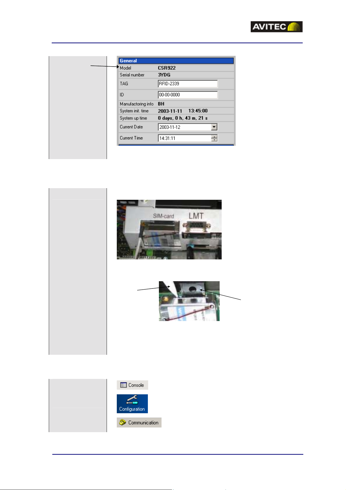
4.4.2 Set Repeater Name (TAG)
Give the repeater a
unique name.
Select “Console” mode”
Select “Configuration” window
Select “Product” page
Alternative 2: Use the
RMC to measure the
uplink at the Hub
© Avitec AB A1009300 A 128 (177)
Page 26
GSM-EDGE Repeaters
PRODUCT DESCRIPTION AND USER'S MANUAL
Insert the name in
this box
4.4.3 Set Up Remote Access
Insert the SIM card
Note! Make sure the SIM card has a Data Call/SMS number and is activated.
The modem is placed next to the LMT port close to the power supply
Pen
SIM card holder
The SIM card holder is on top of the modem
Insert the SIM card by pressing the lever on the left side of the card holder on the
modem (with a pen or another narrow item) so that the card holder pops up. Insert
the SIM card and press the card holder back into place.
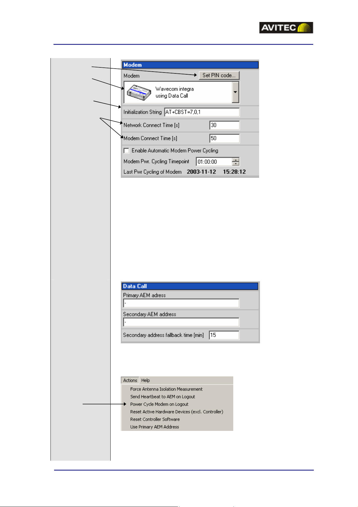
4.4.3.1 Data Call Configuration
Note! If the repeater should be controlled by the AEM this Data Call configuration needs to be made.
Set modem
parameters
© Avitec AB A1009300 A 129 (177)
Select “Console” mode
Select “Configuration” window
Select “Communication” page
Page 27
GSM-EDGE Repeaters
PRODUCT DESCRIPTION AND USER'S MANUAL
Pin Code
Data Call
Initialization string
Connect times
1. Choose Data Call
2. Set pin code, if the SIM card has PIN code request enabled
3. Set the modem initialization string. This string differs bet we en networks.
Primary recommendation is AT+CBST=7,0,1. If remote communication
cannot be established try 7,0,3 or 0,0,3 or 0,0,1.
Data call address
Note! Not to be set at
local installation
Power Cycle Modem
4. Leave Network Connect Time and Modem Connect Time at default values.
5. Tick “Enable Automatic Modem Power Cycling” for the modem to be power
cycled once every 24 hours. Set the time at which the modem should be tested.
This function ensures that the repeater always is logged in to the network.
Note! Do not set addresses for the Data Call. The AEM will call the repeater after
the installation is ready and initiate this communication.
Select Actions and initiate a Power Cycle Modem Logout from the drop-down
menu.
© Avitec AB A1009300 A 130 (177)
Page 28

GSM-EDGE Repeaters
PRODUCT DESCRIPTION AND USER'S MANUAL
Log out
Wait Wait until verification is ready
Log in remotely
Select “Modem”
connection
Select “terminal” mode. Type <LOGOUT>
Note! Do not choose “Disconnect”.
Log in via the modem.
Select
communication port
Save the repeater’s
phone number in the
RMC phone book
Test Test that the remote access is functioning correctly
© Avitec AB A1009300 A 131 (177)
Page 29
GSM-EDGE Repeaters
PRODUCT DESCRIPTION AND USER'S MANUAL
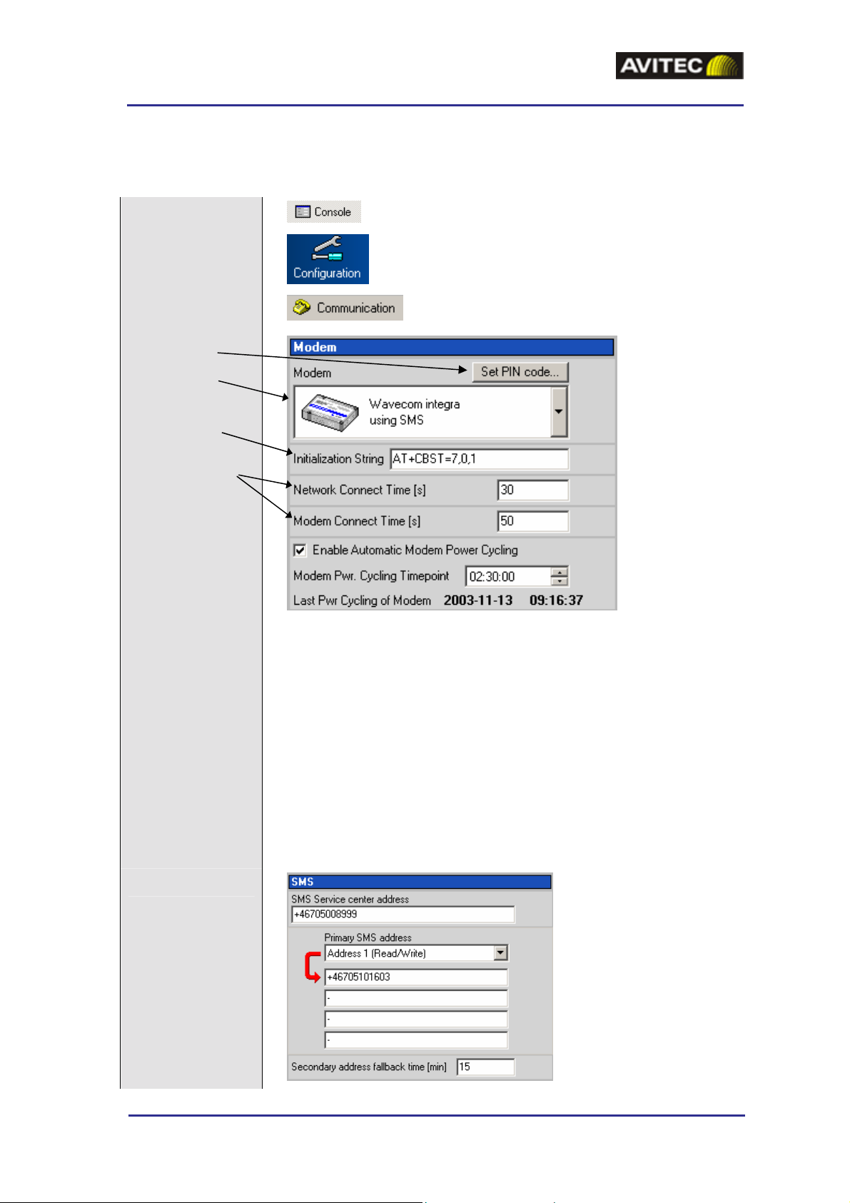
4.4.3.2 SMS Configuration
Note! AEM can not be used if the repeater is configured for SMS communication.
Set modem
parameters
Pin Code
SMS
Initialization string
Connect times
Select “Console” mode
Select “Configuration” window
Select “Communication” page
Set SMS addresses
1. Choose SMS
2. Set pin code, if the SIM card has PIN code request enabled
3. Set modem initialization string. This string di ffers b etween networks. Primary
recommendation is AT+CBST=7,0,1. If remote communication cannot be
established try 7,0,3 or 0,0,3 or 0,0,1.
4. Leave Network Connect Time and Modem Connect Time at default values.
5. Tick “Enable Automatic Modem Power Cycling” for the modem to be power
cycled once every 24 hours. Set the time at which the modem should be tested.
This function ensures that the repeater always is logged in to the network.
© Avitec AB A1009300 A 132 (177)
Page 30
GSM-EDGE Repeaters
PRODUCT DESCRIPTION AND USER'S MANUAL
Set SMS service centre address (the SMSC number to be used).
Set Address 1. This is the address to which all SMS alarms and reports will be sent.
Note! Always set this address.
Set Address 2, 3 and 4 if needed.
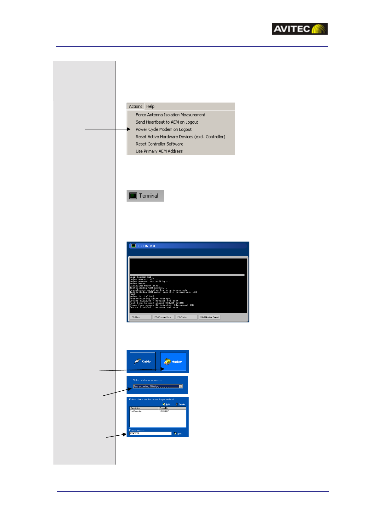
Power Cycle Modem
Select Actions and initiate a Power Cycle Modem Logout from the drop-down
menu.
Log out
Wait Wait until verification is ready
Log in remotely
Select “Modem”
connection
Select “terminal” mode Type <LOGOUT>
Note! Do not choose “Disconnect”.
Log in via the modem
Select
communication port
Save the repeater’s
phone number in the
RMC phone book
Test Test that the remote access is functioning correctly
© Avitec AB A1009300 A 133 (177)
Page 31
GSM-EDGE Repeaters
PRODUCT DESCRIPTION AND USER'S MANUAL
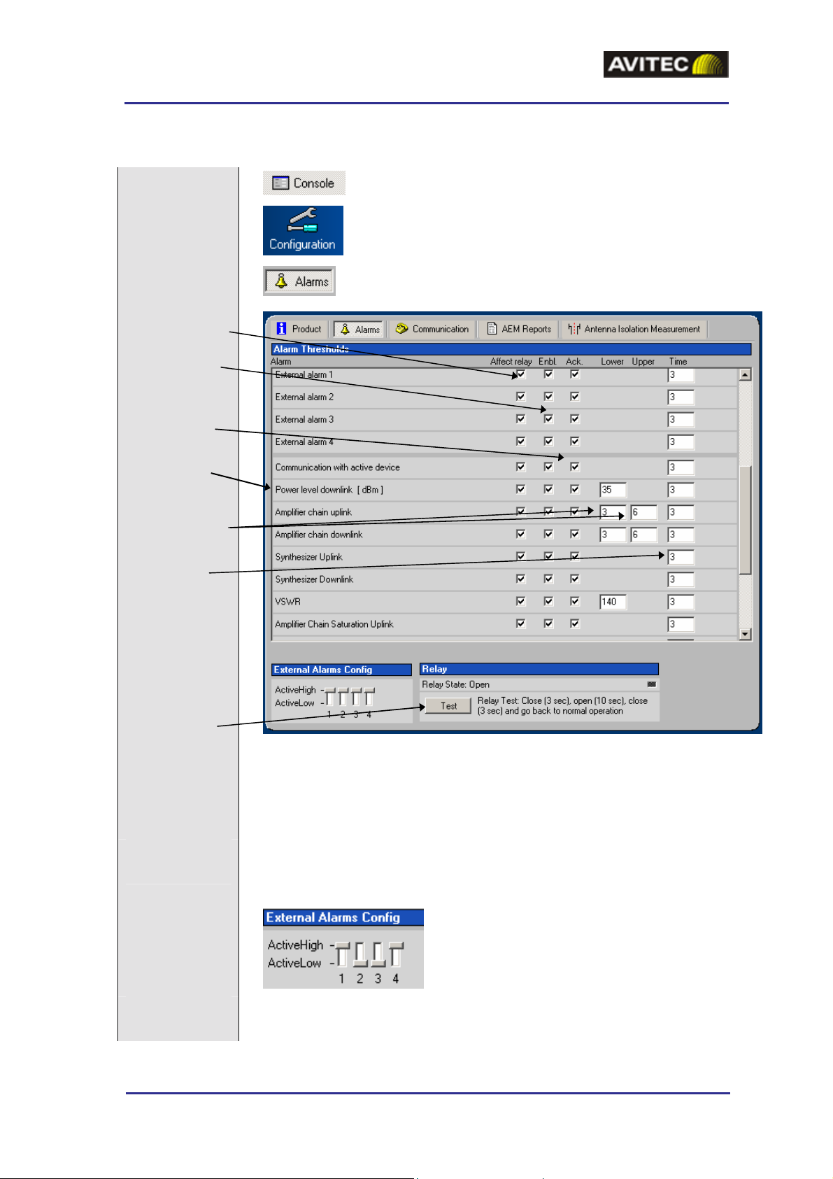
4.4.4 Alarm Configuration
Monitor alarm set
up
Relay connection
enabled
Alarm enabled
Acknowledgement
is required
BCCH alarm
Trigger le vels
Delay time
Select “Console” mode
Select “Configuration” window
Select “Alarms” page
Relay test
Configure external
alarms
The alarm configuration is set up automatically and should be left unmodified, except
for “Power level downlink”.
Note! Power level downlink (BCCH) should be adjusted to fit the installation in regards
to the output power set. In this example a 3 second drop below 35dBm will cause an
alarm.
Four external alarms can be connected to the repeater. See section 4.2.9 Connect
External Alarms.
Set active high or active low for each of these four alarms.
Test the relay The built in relay can be tested by clicking on “Test”. The relay will then be closed for 3
seconds, open for 10 seconds and closed for 3 seconds.
© Avitec AB A1009300 A 134 (177)
Page 32

GSM-EDGE Repeaters
PRODUCT DESCRIPTION AND USER'S MANUAL
4.4.5 Heartbeat Configuration
Monitor heartbeat set
up
Repetition cycle
Retransmissions
Repetition cycle
Select “Console” mode
Select “Configuration” window
Select “AEM Reports” page
4.4.6 AEM Report Configuration
Monitor set up
Select “Console” mode
Select “Configuration” window
Select “AEM Reports” page
Heartbeat
Alarm
© Avitec AB A1009300 A 135 (177)
Page 33

GSM-EDGE Repeaters
PRODUCT DESCRIPTION AND USER'S MANUAL
4.5 Installation Checklists
4.5.1 Channel Selective Repeater Installation
Check box when done
1 Repeater Installation
1.1 Ensure isolation between server and donor antenna is adequate,
repeater’s gain plus 10– 25 dB (depending on situation)
1.2 Measured isolation ____
1.3 Proper grounding made and EMV protection installed
1.4 Cable from donor antenna connected to donor antenna port
1.5 Cable to server antenna connected to server antenna port
1.6 Mains cable connected to the repeater unit
1.7 Cable protection cover bolted to repeater unit, any outdoor
connections waterproofed
2 Repeater Unit Setup
2.1 Repeater switched on
2.2 Power Supply led and Control Module led shows no error
2.3 Channels set to: 1 ___ 2 ___ 3___ 4___
2.4 BCCH in chain 1
2.5 Power level channel 1 downlink set to _____
2.6 Attenuation channel 1 downlink set to ___ (saturation level checked)
2.7 Power level channel 1 uplink set to same as downlink
2.8 Attenuation channel 1 uplink set to same as downlink
2.9 Power level and attenuation channel 2, 3 and 4 set to same levels as channel 1
2.10 Power Supply led and Control Module led shows no error
2.11 Output power downlink channel 1 ____ (reading from RMC)
2.12 Repeater TAG set to ___________
2.13 Repeater secured and locked
Installation date:_______________ Installer signature:_____________________
Site name: ________________Site number: ______________ GPS coordinates:________
© Avitec AB A1009300 A 136 (177)
Page 34

GSM-EDGE Repeaters
PRODUCT DESCRIPTION AND USER'S MANUAL
4.5.2 Preparation Sheet, Frequency Translating Repeater
General
Channels to be repeated____ and _____ => to donor checklist
Link channel (s) to be used ___ and ___ => to donor checklist
Donor Unit
BTS output power + __dBm
Feeder loss between BTS and coupler - ___dB
Coupling loss in coupler - ___dB
Feeder loss between coupler and donor unit - ___dB
__________________________________________________________________
Downlink input power to donor unit (P_in) = __dBm
Desired link power (P
): (+37/+34/+31dBm) ___dBm*
link
=> to donor checklist (Power level downlink)
Required donor downlink gain (G) = P
– Pin = ___dB
link
Donor downlink attenuation = 42 – G (SD) / 45 - G (DD) = ___dB
Attenuation setting to be used (closest larger even number) ___ dB
=> to donor checklist (Attenuation downlink)
Desired uplink ALC level -10/-13/-16 (SD) / -7/-10/-13 (DD) ___dBm
=> to donor checklist (Power level uplink)
Link path
Donor link antenna feeder loss + ___dB
Donor link antenna gain - ___dBi
Link path loss + ___dB
Remote link antenna gain - ___dBi
Remote link antenna feeder loss + ___dB
_________________________________________________________________
Total link loss (L) = ___dB
Remote Unit
Downlink i nput power from link antenna (Pin) = P
Desired remote server power (P
): 40/37/34 (IR) / 43/40/37 (ER) ___dBm
out
-L ___dBm
link
=> to remote checklist (Power level downlink)
Required remote downlink gain (G) = P
– Pin = ___dB
out
Remote unit downlink attenuation = 105–G (IR) / 108-G (ER) = ___dB
© Avitec AB A1009300 A 137 (177)
Page 35

GSM-EDGE Repeaters
PRODUCT DESCRIPTION AND USER'S MANUAL
Attenuation setting to be used (closest larger even number) ___dB
=> to remote checklist (Attenuation downlink)
Desired link power (+37/+34/+31) ___dBm*
=> to remote checklist (Power level uplink)
*Note! Link power should be the same for remote and donor
Date:__________________ Calculated by:_____________________
Site Name: __________________________ Site Number: _____________________
© Avitec AB A1009300 A 138 (177)
Page 36

GSM-EDGE Repeaters
PRODUCT DESCRIPTION AND USER'S MANUAL
4.5.3 Frequency Translating Repeater, Donor Unit
Check box when done
1. Coupler Installation
1.1 -30dB Coupler installed on BTS main antenna feeder
1.2 Type N connector closer to antenna terminated with 50 ohm plug
1.3 Type N connector closer to BTS connected to donor cable
1.4 BT S operating normally with coupler installed verified
1.5 Coupler weath erproof ed
2. Donor Unit Installation
2.1 Proper grounding made and EMV protection installed
2.2 Cable from coupler connected to donor port
2.3 Cable to link antenna connected to link antenna port
2.4 Mains cable connected to the repeater unit
2.5 Cable protection cover bolted to donor unit, any outdoor
connections waterproofed
3. Donor Unit Setup
3.1 Donor unit switched on
3.2 Power Supply led and Control Module led shows no error
3.3 Channels set to: 1 ___ 2 ___
3.4 Link channels set to: 1 ___ 2 ___
3.5 Power level link channel 1 downlink set to _____
3.6 Attenuation link channel 1 downlink set to ___ (according to budget)
3.7 Power level channel 1 uplink set to ___ (according to budget)
3.8 Attenuation channel 1 uplink set to same as link channel downlink
3.9 Power levels and attenuation link channel 2 and channel 2 set to same
levels as link channel and channel 1
3.10 Power Supply led and Control Module led shows no error
3.11 Output power downlink channel 1 ____ (reading from RMC)
3.12 Repeater TAG set to _______________
3.13 Repeater secured and locked
Installation date:_______________ Installer signature:_____________________
Site name: ________________Site number: ______________ GPS coordinates:________
© Avitec AB A1009300 A 139 (177)
Page 37

GSM-EDGE Repeaters
PRODUCT DESCRIPTION AND USER'S MANUAL
4.5.4 Frequency Translating Repeater, Remote Unit
Check box when done
1. Remote Unit Installation
1.1 Ensure adequate isolation between link and serving antenna (>75dB)
1.2 Proper grounding made and EMV protection installed
1.3 Cable from link antenna connected to link antenna port
1.4 Cable to server antenna connected to server antenna port
1.5 Mains cable connected to the repeater unit
1.6 Cable protection cover bolted to donor unit, any outdoor
connections waterproofed
2. Remote Unit Setup
2.1 Remote unit switched on
2.2 Power Supply led and Control Module led shows no error
2.3 Channels set to same as donor
2.4 Link channels set to same as donor
2.5 Power level channel 1 downlink set to ___ (according to budget)
2.6 Attenuation channel 1 downlink set to ___ (according to budget)
2.7 Power level link channel 1 uplink set to same as power level
link channel 1 downlink i n donor unit
2.8 Attenuation link channel 1 uplink set to same as attenuation channel 1
downlink
2.9 Power level and attenuation link c hannel 2 and channel 2 set to same
levels as channel 1
2.10 Power Supply led and Control Module led shows no error
2.11 Output power downlink channel 1 ____ (reading from RMC)
2.12 Repeater TAG set to ___
2.13 Repeater secured and locked
Installation date:_______________ Installer signature:_____________________
Site name: ________________Site number: ______________ GPS coordinates:________
© Avitec AB A1009300 A 140 (177)
Page 38

GSM-EDGE Repeaters
PRODUCT DESCRIPTION AND USER'S MANUAL
5 Maintenance
5.1 General
The system normally operates without any operator intervention or maintenance. In the unlikely event of a
unit failure, the field replaceable components (antenna unit, cables, etc.) should be checked and replaced if
faulty and the system restored. A failed unit can be removed and replaced with a spare while the rest of the
system (other repeaters) is operating. However, the power supply of the failed repeater should be isolated
from AC mains and DC power before any module is replaced.
Should the system malfunction, the condition of the antenna systems as well as the continuity of the cabling
should be checked before replacing any of the repeater modules.
Caution
Please be aware that the equipment may, during certain conditions become very warm and can cause minor
injuries if handled without any protection, such as gloves.
5.2 Preventive Maintenance
The Avitec repeaters do not require any preventative maintenance apart from changing the backup battery
once every three years.
Caution
Risk of explosion if battery is replaced by an incorrect type.
Dispose of used batteries according to local laws and instructions.
© Avitec AB A1009300 A 141 (177)
Page 39

GSM-EDGE Repeaters
PRODUCT DESCRIPTION AND USER'S MANUAL
6 Specifications
6.1 CSR 922
Electrical Specifications
Frequency range Uplink, UL 880 – 915 MHz (E-GSM900)
Frequency range Downlink, DL 925 – 960 MHz (E-GSM900)
Frequency range Uplink, UL 876 – 911 MHz (R-GSM900)
Frequency range Downlink, DL 921 – 956 MHz (R-GSM900)
Operational bandwidth 35 MHz
Number of channels 1 – 2
Channel programming 200 kHz channel spacing
Selectivity > 60 dB at 400 kHz
> 70 dB at 600 kHz
Ripple in pass band < 2 dB
Sensitivity < - 109 dBm at S/N 9 dB
Noise figure 2.5 dB typical, < 3 dB at max gain
Maximum input level, non destructive +10 dBm
Propagation delay 5.5 µs typical
Output power per carrier (UL/DL) +37 dBm GSM/ GMSK
+34 dBm EDGE / 8-PSK average power
Modulation Accuracy
GSM / GMSK < 2.5 ° RMS and < 10 ° peak at +37 dBm
EDGE / 8-PSK < 3 % EVM RMS at + 34 dBm
Intermodulation < - 36 dBm (two carriers at + 37 dBm, 600 kHz spacing)
Spurious responses < - 36 dBm for 9 kHz – 1 GHz
< - 30 dBm for 1 GHz – 13 GHz
Gain 60 – 90 dB, adjustable, in 1 dB steps
System impedance 50 ohm
Return loss at antenna connections > 16 dB
Antenna connectors DIN 7/16
Electrical ratings 110/230 VAC, 50/60 Hz or -48 VDC
Power Consumption 100 W typical / 200 W maximum (traffic dependent)
© Avitec AB A1009300 A 142 (177)
Page 40

GSM-EDGE Repeaters
PRODUCT DESCRIPTION AND USER'S MANUAL
Mechanical Specifications
Dimensions 470 x 340 x 145 mm
Enclosure Aluminum (IP 65)
Weight 16 kg
Environmental Specifications
EMC See compliance below
Operating Temperature - 25 to + 55 ° C
Storage - 30 to + 70 ° C
Humidity ETSI EN 300 019-2-4 (see compliance below)
MTBF > 100 000 hrs
Complies with R&TTE Directive including
ETS EN 301 502 (ETS EN 300 609-4/GSM 11.26)
ETS EN 301 498-8
EN 60 950
© Avitec AB A1009300 A 143 (177)
Page 41

GSM-EDGE Repeaters
PRODUCT DESCRIPTION AND USER'S MANUAL
6.2 CSR 924
Electrical Specifications
Frequency range Uplink, UL 880 – 915 MHz (E-GSM900)
Frequency range Downlink, DL 925 – 960 MHz (E-GSM900)
Frequency range Uplink, UL 876 – 911 MHz (R-GSM900)
Frequency range Downlink, DL 921 – 956 MHz (R-GSM900)
Operational bandwidth 35 MHz
Number of channels 1 – 4
Channel programming 200 kHz channel spacing
Selectivity > 60 dB at 400 kHz
> 70 dB at 600 kHz
Ripple in pass band < 2 dB
Sensitivity < - 108 dBm at S/N 9 dB
Noise figure 3 dB typical, < 3.5 dB at max gain
Maximum input level, non destructive +10 dBm
Propagation delay 5.5 µs typical
Output power per carrier (UL/DL) +34 dBm GSM/ GMSK
+31 dBm EDGE / 8-PSK average power
Modulation Accuracy
GSM / GMSK < 2.5 ° RMS and < 10 ° peak at +34 dBm
EDGE / 8-PSK < 3 % EVM RMS at +31 dBm
Intermodulation < - 36 dBm (two carriers at + 34 dBm, 600 kHz spacing)
Spurious responses < - 36 dBm for 9 kHz – 1 GHz
< - 30 dBm for 1 GHz – 13 GHz
Gain 54 – 84 dB, adjustable, in 1 dB steps
System impedance 50 ohm
Return loss at antenna connections > 16 dB
Antenna connectors DIN 7/16
Electrical ratings 110/230 VAC, 50/60 Hz or -48 VDC
Power Consumption 180 W typical / 400 W maximum (traffic dependent)
© Avitec AB A1009300 A 144 (177)
Page 42

GSM-EDGE Repeaters
PRODUCT DESCRIPTION AND USER'S MANUAL
Mechanical Specifications
Dimensions 470 x 340 x 220 mm
Enclosure Aluminum (IP 65)
Weight 30 kg
Environmental Specifications
EMC See compliance below
Operating Temperature - 25 to + 55 °C
Storage - 30 to + 70 °C
Humidity ETSI EN 300 019-2-4 (see compliance below)
MTBF > 100 000 hrs
Complies with R&TTE Directive including
ETS EN 301 502 (ETS EN 300 609-4/GSM 11.26)
ETS EN 301 498-8
EN 60 950
© Avitec AB A1009300 A 145 (177)
Page 43

GSM-EDGE Repeaters
PRODUCT DESCRIPTION AND USER'S MANUAL
6.3 CSR 924 H
Electrical Specifications
Frequency Ranges
Frequency range Uplink, UL 880 – 915 MHz (E-GSM900)
Frequency range Downlink, DL 925 – 960 MHz (E-GSM900)
Frequency range Uplink, UL 876 – 911 MHz (R-GSM900)
Frequency range Downlink, DL 921 – 956 MHz (R-GSM900)
Operational bandwidth 35 MHz
Number of channels 1 – 4
Channel programming 200 kHz channel spacing
Selectivity > 60 dB at 400 kHz
> 70 dB at 600 kHz
Ripple in passband < 2 dB
Sensitivity < - 108 dBm at S/N 9 dB
Noise figure 3 dB typical, < 3,5 dB at max gain
Maximum input level, non destructive + 10 dBm
Propagation delay 5,5 µs typical
Output power per carrier, DL + 37 dBm GSM/ GMSK,
+ 34 dBm EDGE / 8-PSK average power
Output power per carrier, UL + 34 dBm GSM/ GMSK
+ 31 dBm EDGE / 8-PSK average power
Modulation Accuracy
GSM / GMSK < 2.5 ° RMS and < 10 ° peak at + 37 dBm
EDGE / 8-PSK < 3 % EVM RMS at + 34 dBm
Intermodulation < - 36 dBm (two carriers at + 37 dBm, 600 kHz spacing)
Spurious responses < - 36 dBm for 9 kHz – 1 GHz
< - 30 dBm for 1 GHz – 13 GHz
Gain DL/UL 63 – 93 dB, adjustable, in 1 dB steps
System impedance 50 Ω
Return loss at antenna connections > 16 dB
Antenna connectors DIN 7/16
Electrical ratings 110/230 VAC, 50/60 Hz or -48 VDC
Power Consumption 180 W typical / 400 W maximum
© Avitec AB A1009300 A 146 (177)
Page 44

GSM-EDGE Repeaters
PRODUCT DESCRIPTION AND USER'S MANUAL
Mechanical Specifications
Dimensions 470 x 340 x 220 mm
Enclosure Aluminium (IP 65)
Weight 30 kg
Environmental Specifications
EMC See compliance below
Operating Temperature - 25 to + 55 ° C
Storage - 30 to + 70 ° C
Humidity ETSI EN 300 019-2-4 ( see compliance below)
MTBF > 100000 hrs
Complies with R&TTE Directive including
ETS EN 301 502 (ETS EN 300 609-4 / GSM 11.26)
ETS EN 301 498-8
EN 60 950
© Avitec AB A1009300 A 147 (177)
Page 45

GSM-EDGE Repeaters
PRODUCT DESCRIPTION AND USER'S MANUAL
6.4 CSR1822
Electrical Specifications
Frequency range Uplink, UL 1710 - 1785 MHz (DCS-1800)
Frequency range Downlink, DL 1805 - 1885 MHz (DCS-1800)
Operational bandwidth 75 MHz
Number of channels 1 - 2
Channel programming 200 kHz Channel spacing
Selectivity > 60 dB at 400 kHz
>70 dB at 600 kHz
Ripple in passband < 2 dB
Sensitivity < - 109 dBm at S/N 9 dB
Noise figure 2.5 dB typical, < 3 dB at max gain
Maximum input level, non destructive + 10 dBm
Propagation delay 5,5 µs typical
Output power per carrier (UL/DL) + 37dBm GSM/ GMSK
+ 34 dBm EDGE / 8-PSK average power
Modulation Accuracy
GSM / GMSK < 2.5 ° RMS and < 10 ° peak at +37 dBm
EDGE / 8-PSK < 3 % EVM RMS at + 34 dBm
Intermodulation < - 36 dBm (two carriers at + 37 dBm, 600 kHz spacing)
Spurious responses < - 36 dBm for 9 kHz - 1 GHz
< - 30 dBm for 1 GHz - 13 GHz
Gain 60 - 90 dB, adjustable, in 1 dB steps
System impedance 50 ohm
Return loss at antenna connections > 16 dB
Antenna connectors DIN 7/16
Electrical ratings 110/230 VAC, 50/60 Hz or -48 VDC
Power Consumption 100 W typical / 200 W maximum (traffic dependent)
Mechanical Specifications
Dimensions 470 x 340 x 145 mm
Enclosure Aluminum (IP 65)
Weight 16 kg
© Avitec AB A1009300 A 148 (177)
Page 46

GSM-EDGE Repeaters
PRODUCT DESCRIPTION AND USER'S MANUAL
Environmental Specifications
EMC See compliance below
Operating Temperature - 25 to + 55 ° C
Storage - 30 to + 70 ° C
Humidity ETSI EN 300 019-2-4 (see compliance below)
MTBF > 100 000 hrs
Complies with R& TTE Directive including
ETS EN 301 502 (ETS EN 300 609-4 / GSM 11.26 )
ETS EN 301 498-8
EN 60 950
© Avitec AB A1009300 A 149 (177)
Page 47

GSM-EDGE Repeaters
PRODUCT DESCRIPTION AND USER'S MANUAL
6.5 CSR1824
Electrical Specifications
Frequency range Uplink, UL 1710 - 1785 MHz (DCS-1800)
Frequency range Downlink, DL 1805 - 1885 MHz (DCS-1800)
Operational bandwidth 75 MHz
Number of channels 1 - 4
Channel programming 200 kHz channel spacing
Selectivity > 60 dB at 400 kHz
>70 dB at 600 kHz
Ripple in passband < 2 dB
Sensitivity < - 108 dBm at S/N 9 dB
3 dB typical, < 3,5 dB at max gain
Maximum input level, non destructive + 10 dBm
Propagation delay 5,5 µs typical
Output power per carrier (UL/DL ) + 34 dBm GSM/ GMSK
+ 31 dBm EDGE / 8-PSK average power
Modulation Accuracy
GSM / GMSK < 2.5 ° RMS and < 10 ° peak at +37 dBm
EDGE / 8-PSK < 3 % EVM RMS at + 34 dBm
Intermodulation < - 36 dBm (two carriers at + 34 dBm, 600 kHz spacing)
Spurious responses < - 36 dBm for 9 kHz - 1 GHz
< - 30 dBm for 1 GHz - 13 GHz
Gain 54 - 84 dB, adjustable, in 1 dB steps.
System impedance 50 ohm
Return loss at antenna connections > 16 dB
Antenna connectors DIN 7/16
Electrical ratings 110/230 VAC, 50/60 Hz or -48 VDC
Power Consumption 180 W typical / 400 W maximum (traffic dependent)
Mechanical Specifications
Dimensions 470 x 340 x 220 mm
Enclosure Aluminum (IP 65)
Weight 30 kg
© Avitec AB A1009300 A 150 (177)
Page 48

GSM-EDGE Repeaters
PRODUCT DESCRIPTION AND USER'S MANUAL
Environmental Specifications
EMC See compliance below
Operating Temperature - 25 to + 55 ° C
Storage - 30 to + 70 ° C
Humidity ETSI EN 300 019-2-4 (see compliance below)
MTBF > 100 000 hrs
Complies with R& TTE Directive including
ETS EN 301 502 (ETS EN 300 609-4 / GSM 11.26 )
ETS EN 301 498-8
EN 60 950
© Avitec AB A1009300 A 151 (177)
Page 49

GSM-EDGE Repeaters
PRODUCT DESCRIPTION AND USER'S MANUAL
6.6 CSR1922
Electrical Specifications
Frequency range Uplink, UL 1850 - 1910 MHz (PCS-1900)
Frequency range Downlink, DL 1930 - 1990 MHz (PCS-1900)
Operational bandwidth 60 MHz
Number of channels 1 - 2
Channel programming 200 kHz Channel spacing
Selectivity > 60 dB at 400 kHz
>70 dB at 600 kHz
Ripple in passband < 2 dB
Sensitivity < - 109 dBm at S/N 9 dB
Noise figure 2.5 dB typical, < 3 dB at max gain
Maximum input level, non destructive + 10 dBm
Propagation delay 5,5 µs typical
Output power per carrier (UL/DL) + 37dBm GSM/ GMSK
+ 34 dBm EDGE / 8-PSK average power
Modulation Accuracy
GSM / GMSK < 2.5 ° RMS and < 10 ° peak at +37 dBm
EDGE / 8-PSK < 3 % EVM RMS at + 34 dBm
Intermodulation < - 36 dBm (two carriers at + 37 dBm, 600 kHz spacing)
Spurious responses < - 36 dBm for 9 kHz - 1 GHz
< - 30 dBm for 1 GHz - 13 GHz
Gain 60 - 90 dB, adjustable, in 1 dB steps
System impedance 50 ohm
Return loss at antenna connections > 16 dB
Antenna connectors DIN 7/16
Electrical ratings 110/230 VAC, 50/60 Hz or -48 VDC
Power Consumption 100 W typical / 200 W maximum (traffic dependent)
Mechanical Specifications
Dimensions 470 x 340 x 145 mm
Enclosure Aluminum (IP 65)
Weight 16 kg
© Avitec AB A1009300 A 152 (177)
Page 50

GSM-EDGE Repeaters
PRODUCT DESCRIPTION AND USER'S MANUAL
Environmental Specifications
EMC See compliance below
Operating Temperature - 25 to + 55 ° C
Storage - 30 to + 70 ° C
Humidity ETSI EN 300 019-2-4 (see compliance below)
MTBF > 100 000 hrs
Complies with R& TTE Directive including
ETS EN 301 502 (ETS EN 300 609-4 / GSM 11.26 )
ETS EN 301 498-8
EN 60 950
© Avitec AB A1009300 A 153 (177)
Page 51

GSM-EDGE Repeaters
PRODUCT DESCRIPTION AND USER'S MANUAL
6.7 CSR1924
Electrical Specifications
Frequency range Uplink, UL 1850 - 1910 MHz (PCS-1900)
Frequency range Downlink, DL 1930 - 1990 MHz (PCS-1900)
Operational bandwidth 60 MHz
Number of channels 1 - 4
Channel programming 200 kHz channel spacing
Selectivity > 60 dB at 400 kHz
>70 dB at 600 kHz
Ripple in passband < 2 dB
Sensitivity < - 108 dBm at S/N 9 dB
3 dB typical, < 3,5 dB at max gain
Maximum input level, non destructive + 10 dBm
Propagation delay 5,5 µs typical
Output power per carrier (UL/DL ) + 34 dBm GSM/ GMSK
+ 31 dBm EDGE / 8-PSK average power
Modulation Accuracy
GSM / GMSK < 2.5 ° RMS and < 10 ° peak at +37 dBm
EDGE / 8-PSK < 3 % EVM RMS at + 34 dBm
Intermodulation < - 36 dBm (two carriers at + 34 dBm, 600 kHz spacing)
Spurious responses < - 36 dBm for 9 kHz - 1 GHz
< - 30 dBm for 1 GHz - 13 GHz
Gain 54 - 84 dB, adjustable, in 1 dB steps
System impedance 50 ohm
Return loss at antenna connections > 16 dB
Antenna connectors DIN 7/16
Electrical ratings 110/230 VAC, 50/60 Hz or -48 VDC
Power Consumption 180 W typical / 400 W maximum (traffic dependent)
Mechanical Specifications
Dimensions 470 x 340 x 220 mm
Enclosure Aluminum (IP 65)
Weight 30 kg
© Avitec AB A1009300 A 154 (177)
Page 52

GSM-EDGE Repeaters
PRODUCT DESCRIPTION AND USER'S MANUAL
Environmental Specifications
EMC See compliance below
Operating Temperature - 25 to + 55 ° C
Storage - 30 to + 70 ° C
Humidity ETSI EN 300 019-2-4 (see compliance below)
MTBF > 100 000 hrs
Complies with R& TTE Directive including
ETS EN 301 502 (ETS EN 300 609-4 / GSM 11.26 )
ETS EN 301 498-8
EN 60 950
© Avitec AB A1009300 A 155 (177)
Page 53

GSM-EDGE Repeaters
PRODUCT DESCRIPTION AND USER'S MANUAL
6.8 CSFT 922
Electrical Specification
Frequency range Uplink, UL 880 – 915 MHz (E-GSM900)
Frequency range Downlink, DL 925 – 960 MHz (E-GSM900)
Frequency range Uplink, UL 876 – 911 MHz (R-GSM900)
Frequency range Downlink, DL 921 – 956 MHz (R-GSM900)
Operational bandwidth 35 MHz
Number of channels 1 – 2
Channel programming 200 kHz Channel spacing
Selectivity > 60 dB at 400 kHz
> 70 dB at 600 kHz
Ripple in passband < 2 dB
Sensitivity
Donor unit (SD) and (DD)
UL < - 109 dBm at S/N 9 dB
DL N/A
Remote unit (IR) and (ER) < - 109 dBm at S/N 9 dB
Noise figure
Donor unit (SD) and (DD)
UL 2.5 dB typical, < 3 dB at max gain
DL N/A
Remote unit (IR) and (ER) UL/DL 2.5 dB typical, < 3 dB at max gain
Maximum input level, no damage
Donor unit (SD) and (DD)
UL + 23 dBm
DL + 10 dBm
Remote unit (IR) and (ER) UL/DL + 10 dBm
Propagation delay 5.5 µs typical
© Avitec AB A1009300 A 156 (177)
Page 54

GSM-EDGE Repeaters
PRODUCT DESCRIPTION AND USER'S MANUAL
Output power per carrier
Donor unit (SD)
DL + 37 dBm GSM/ GMSK
+ 34 dBm EDGE / 8-PSK average power
UL - 10 dBm GSM/ GMSK
- 13 dBm EDGE / 8-PSK average power
Donor unit (DD)
DL + 37 dBm GSM/ GMSK
+ 34 dBm EDGE / 8-PSK average power
UL - 7 dBm GSM/ GMSK
- 10 dBm EDGE / 8-PSK average power
Remote unit (IR)
DL + 40 dBm GSM/ GMSK
+ 37 dBm EDGE / 8-PSK average power
UL + 37 dBm GSM/ GMSK
+ 34 dBm EDGE / 8-PSK average power
Remote unit (ER)
DL + 43 dBm GSM/ GMSK
+ 40 dBm EDGE / 8-PSK average power
UL + 37 dBm GSM/ GMSK
+ 34 dBm EDGE / 8-PSK average power
Gain
Donor unit (SD) max 42 dB, adjustable, in 1 dB steps
Donor unit (DD) max 45 dB, adjustable, in 1 dB steps
Remote unit (IR)
DL/UL 75 - 105 dB, adjustable, in 1 dB steps
Remote unit (ER)
DL/UL 78 - 108 dB, adjustable, in 1 dB steps
Gain Flatness (200 kHz BW) ± 1 dB
Gain Flatness (15 MHz BW) ± 1 dB
Input to Link Channel Fre quency Erro r < 1 x 10
-9
Modulation Accuracy
Donor unit (SD) and (DD)
DL
GSM / GMSK < 2.5 ° RMS and < 10 ° peak at +33 dBm
EDGE / 8-PSK < 3 % EVM RMS at +30 dBm average power
UL
GSM / GMSK < 2.5 ° RMS and < 10 ° peak at -10 dBm
© Avitec AB A1009300 A 157 (177)
Page 55

GSM-EDGE Repeaters
PRODUCT DESCRIPTION AND USER'S MANUAL
EDGE / 8-PSK < 3 % EVM RMS at -13 dBm average power
Remote unit (IR)
DL
GSM / GMSK < 2.5 ° RMS and < 10 ° peak at +40 dBm
EDGE / 8-PSK < 4 % EVM RMS at +37 dBm average power
UL
GSM / GMSK < 2.5 ° RMS and < 10 ° peak at +37 dBm
EDGE / 8-PSK < 3 % EVM RMS at +34 dBm average power
Remote unit (ER)
DL
GSM / GMSK < 2.5 ° RMS and < 10 ° peak at +43 dBm
EDGE / 8-PSK < 4 % EVM RMS at +40 dBm average power
UL
GSM / GMSK < 2.5 ° RMS and < 10 ° peak at +37 dBm
EDGE / 8-PSK < 3 % EVM RMS at +34 dBm average power
Intermodulation
Donor unit (SD) and (DD) < -36 dBm (two carriers at + 33 dBm DL, 600 kHz
spacing)
< -70 dBm (two carriers at -10 dBm UL, 600 kHz
spacing)
Remote unit (IR) < -36 dBm (two carriers at + 40 dBm DL, 600 kHz
spacing)
< -36 dBm (two carriers at +37 dBm UL, 600 kHz
spacing)
Remote unit (ER) < -36 dBm (two carriers at + 43 dBm DL, 600 kHz
spacing)
< -36 dBm (two carriers at +37 dBm UL, 600 kHz
spacing)
Spurious responses < - 36 dBm for 9 kHz – 1 GHz
< - 30 dBm for 1 GHz – 13 GHz
System impedance 50 ohm
Return loss at antenna connections > 16 dB
Antenna connectors DIN 7/16
Electrical ratings 110/230 VAC, 50/60 Hz or -48 VDC
Power Consumption 100 W typical / 200 W maximum (traffic dependent)
Mechanical Specifications
Dimensions 470 x 340 x 145 mm
© Avitec AB A1009300 A 158 (177)
Page 56

GSM-EDGE Repeaters
PRODUCT DESCRIPTION AND USER'S MANUAL
Enclosure Aluminum (IP 65)
Weight 16 kg
Environmental Specifications
EMC See compliance below
Operating Temperature - 25 to + 55 ° C
Storage - 30 to + 70 ° C
Humidity ETSI EN 300 019-2-4 (see compliance below)
MTBF > 100 000 hrs
Complies with R& TTE Directive including
ETS EN 301 502 (ETS EN 300 609-4 / GSM 11.26)
ETS EN 301 498-8
EN 60 950
© Avitec AB A1009300 A 159 (177)
Page 57

GSM-EDGE Repeaters
PRODUCT DESCRIPTION AND USER'S MANUAL
6.9 CSFT 1822
Electrical Specifications
Frequency range Uplink, UL 1710 - 1785 MHz (DCS 1800)
Frequency range Downlink, DL 1805 - 1880 MHz (DCS 1800)
Operational bandwidth 75 MHz
Number of channels 1 - 2
Channel programming 200 kHz Channel spacing
Selectivity > 60 dB at 400 kHz
> 70 dB at 600 kHz
Ripple in passband < 2 dB
Sensitivity
Donor unit (SD) and (DD)
UL < - 109 dBm at S/N 9 dB
DL N/A
Remote unit (IR) and (ER) < - 109 dBm at S/N 9 dB
Noise figure
Donor unit (SD) and (DD)
UL 2.5 dB typical, < 3 dB at max gain
DL N/A
Remote unit (IR) and (ER) UL/DL 2.5 dB typical, < 3 dB at max gain
Maximum input level, no damage
Donor unit (SD) and (DD)
UL + 23 dBm
DL + 10 dBm
Remote unit (IR) and (ER) UL/DL + 10 dBm
Propagation delay 5,5 µs typical
Output power per carrier
Donor unit (SD)
DL + 37 dBm GSM/ GMSK
+ 34 dBm EDGE / 8-PSK average power
UL - 10 dBm GSM/ GMSK
- 13 dBm EDGE / 8-PSK average power
Donor unit (DD)
© Avitec AB A1009300 A 160 (177)
Page 58

GSM-EDGE Repeaters
PRODUCT DESCRIPTION AND USER'S MANUAL
DL + 37 dBm GSM/ GMSK
+ 34 dBm EDGE / 8-PSK average power
UL - 10 dBm GSM/ GMSK
- 13 dBm EDGE / 8-PSK average power
Remote unit (IR)
DL + 40 dBm GSM/ GMSK
+ 37 dBm EDGE / 8-PSK average power
UL + 37 dBm GSM/ GMSK
+ 34 dBm EDGE / 8-PSK average power
Remote unit (ER)
DL + 43 dBm GSM/ GMSK
+ 40 dBm EDGE / 8-PSK average power
UL + 37 dBm GSM/ GMSK
+ 34 dBm EDGE / 8-PSK average power
Gain
Donor unit (SD) max 42 dB, adjustable, in 1 dB steps
Donor unit (DD) max 45 dB, adjustable, in 1 dB steps
Remote unit (IR)
DL/UL 75 - 105 dB, adjustable, in 1 dB steps
Remote unit (ER)
DL/UL 78 - 108 dB, adjustable, in 1 dB steps
Gain Flatness (200 kHz BW) ± 1 dB
Gain Flatness (15 MHz BW) ± 1 dB
Input to Link Channel Fre quency Erro r < 1 x 10
-9
Modulation Accuracy
Donor unit (SD) and (DD)
DL
GSM / GMSK < 2.5 ° RMS and < 10 ° peak at +33 dBm
EDGE / 8-PSK < 3 % EVM RMS at +30 dBm average power
UL
GSM / GMSK < 2.5 ° RMS and < 10 ° peak at -10 dBm
EDGE / 8-PSK < 3 % EVM RMS at -13 dBm average power
Remote unit (IR)
DL
GSM / GMSK < 2.5 ° RMS and < 10 ° peak at +40 dBm
EDGE / 8-PSK < 4 % EVM RMS at +37 dBm average power
UL
© Avitec AB A1009300 A 161 (177)
Page 59

GSM-EDGE Repeaters
PRODUCT DESCRIPTION AND USER'S MANUAL
GSM / GMSK < 2.5 ° RMS and < 10 ° peak at +37 dBm
EDGE / 8-PSK < 3 % EVM RMS at +34 dBm average power
Remote unit (ER)
DL
GSM / GMSK < 2.5 ° RMS and < 10 ° peak at +43 dBm
EDGE / 8-PSK < 4 % EVM RMS at +40 dBm average power
UL
GSM / GMSK < 2.5 ° RMS and < 10 ° peak at +37 dBm
EDGE / 8-PSK < 3 % EVM RMS at +34 dBm average power
Intermodulation
Donor unit (SD) and (DD) < -36 dBm (two carriers at + 33 dBm DL, 600 kHz
spacing)
< -70 dBm (two carriers at -10 dBm UL, 600 kHz
spacing)
Remote unit (IR) < -36 dBm (two carriers at + 40 dBm DL, 600 kHz
spacing)
< -36 dBm (two carriers at +37 dBm UL, 600 kHz
spacing)
Remote unit (ER) < -36 dBm (two carriers at + 43 dBm DL, 600 kHz
spacing)
< -36 dBm (two carriers at +37 dBm UL, 600 kHz
spacing)
Spurious responses < - 36 dBm for 9 kHz - 1 GHz
< - 30 dBm for 1 GHz - 13 GHz
System impedance 50 ohm
Return loss at antenna connections > 16 dB
Antenna connectors DIN 7/16
Electrical ratings 110/230 VAC, 50/60 Hz or -48 VDC
Power Consumption 100 W typical / 200 W maximum (traffic dependent)
Mechanical Specifications
Dimensions 470 x 340 x 145 mm
Enclosure Aluminum (IP 65)
Weight 16 kg
Environmental Specifications
EMC See compliance below
Operating Temperature - 25 to + 55 ° C
Storage - 30 to + 70 ° C
© Avitec AB A1009300 A 162 (177)
Page 60

GSM-EDGE Repeaters
PRODUCT DESCRIPTION AND USER'S MANUAL
Humidity ETSI EN 300 019-2-4 (see compliance below)
MTBF > 100 000 hrs
Complies with R& TTE Directive including
ETS EN 301 502 (ETS EN 300 609-4 / GSM 11.26)
ETS EN 301 498-8
EN 60 950
© Avitec AB A1009300 A 163 (177)
Page 61

GSM-EDGE Repeaters
PRODUCT DESCRIPTION AND USER'S MANUAL
6.10 CSFT 1922
Electrical Specifications
Frequency range Uplink, UL 1850 - 1920 MHz (PS 1900)
Frequency range Downlink, DL 1930 - 1990 MHz (PS 1900)
Operational bandwidth 60 MHz
Number of channels 1 - 2
Channel programming 200 kHz Channel spacing
Selectivity > 60 dB at 400 kHz
> 70 dB at 600 kHz
Ripple in passband < 2 dB
Sensitivity
Donor unit (SD) and (DD)
UL < - 109 dBm at S/N 9 dB
DL N/A
Remote unit (IR) and (ER) < - 109 dBm at S/N 9 dB
Noise figure
Donor unit (SD) and (DD)
UL 2.5 dB typical, < 3 dB at max gain
DL N/A
Remote unit (IR) and (ER) UL/DL 2.5 dB typical, < 3 dB at max gain
Maximum input level, no damage
Donor unit (SD) and (DD)
UL + 23 dBm
DL + 10 dBm
Remote unit (IR) and (ER) UL/DL + 10 dBm
Propagation delay 5,5 µs typical
Output power per carrier
Donor unit (SD)
DL + 37 dBm GSM/ GMSK
+ 34 dBm EDGE / 8-PSK average power
UL - 10 dBm GSM/ GMSK
- 13 dBm EDGE / 8-PSK average power
Donor unit (DD)
© Avitec AB A1009300 A 164 (177)
Page 62

GSM-EDGE Repeaters
PRODUCT DESCRIPTION AND USER'S MANUAL
DL + 37 dBm GSM/ GMSK
+ 34 dBm EDGE / 8-PSK average power
UL - 7 dBm GSM/ GMSK
- 10 dBm EDGE / 8-PSK average power
Remote unit (IR)
DL + 40 dBm GSM/ GMSK
+ 37 dBm EDGE / 8-PSK average power
UL + 37 dBm GSM/ GMSK
+ 34 dBm EDGE / 8-PSK average power
Remote unit (ER)
DL + 43 dBm GSM/ GMSK
+ 40 dBm EDGE / 8-PSK average power
UL + 37 dBm GSM/ GMSK
+ 34 dBm EDGE / 8-PSK average power
Gain
Donor unit (SD) max 42 dB, adjustable, in 1 dB steps
Donor unit (DD) max 45 dB, adjustable, in 1 dB steps
Remote unit (IR)
DL/UL 75 - 105 dB, adjustable, in 1 dB steps
Remote unit (ER)
DL/UL 78 - 108 dB, adjustable, in 1 dB steps
Gain Flatness (200 kHz BW) ± 1 dB
Gain Flatness (15 MHz BW) ± 1 dB
Link to output Channel Frequency Err or < 1 x 10⁻⁹
Modulation Accuracy
Donor unit (SD) and (DD)
DL
GSM / GMSK < 2.5 ° RMS and < 10 ° peak at +33 dBm
EDGE / 8-PSK < 3 % EVM RMS at +30 dBm average power
UL
GSM / GMSK < 2.5 ° RMS and < 10 ° peak at -10 dBm
EDGE / 8-PSK < 3 % EVM RMS at -13 dBm average power
Remote unit (IR)
DL
GSM / GMSK < 2.5 ° RMS and < 10 ° peak at +40 dBm
EDGE / 8-PSK < 4 % EVM RMS at +37 dBm average power
UL
© Avitec AB A1009300 A 165 (177)
Page 63

GSM-EDGE Repeaters
PRODUCT DESCRIPTION AND USER'S MANUAL
GSM / GMSK < 2.5 ° RMS and < 10 ° peak at +37 dBm
EDGE / 8-PSK < 3 % EVM RMS at +34 dBm average power
Remote unit (ER)
DL
GSM / GMSK < 2.5 ° RMS and < 10 ° peak at +43 dBm
EDGE / 8-PSK < 4 % EVM RMS at +40 dBm average power
UL
GSM / GMSK < 2.5 ° RMS and < 10 ° peak at +37 dBm
EDGE / 8-PSK < 3 % EVM RMS at +34 dBm average power
Intermodulation
Donor unit (SD) and (DD) < -36 dBm (two carriers at + 33 dBm DL, 600 kHz
spacing)
< -70 dBm (two carriers at -10 dBm UL, 600 kHz
spacing)
Remote unit (IR) < -36 dBm (two carriers at + 40 dBm DL, 600 kHz
spacing)
< -36 dBm (two carriers at +37 dBm UL, 600 kHz
spacing)
Remote unit (ER) < -36 dBm (two carriers at + 43 dBm DL, 600 kHz
spacing)
< -36 dBm (two carriers at +37 dBm UL, 600 kHz
spacing)
Spurious responses < - 36 dBm for 9 kHz - 1 GHz
< - 30 dBm for 1 GHz - 13 GHz
System impedance 50 ohm
Return loss at antenna connections > 16 dB
Antenna connectors DIN 7/16
Electrical ratings 110/230 VAC, 50/60 Hz or -48 VDC
Power Consumption 100 W typical / 200 W maximum (traffic dependent)
Mechanical Specifications
Dimensions 470 x 340 x 145 mm
Enclosure Aluminum (IP 65)
Weight 16 kg
Environmental Specifications
EMC See compliance below
Operating Temperature - 25 to + 55 ° C
© Avitec AB A1009300 A 166 (177)
Page 64

GSM-EDGE Repeaters
PRODUCT DESCRIPTION AND USER'S MANUAL
Storage - 30 to + 70 ° C
Humidity ETSI EN 300 019-2-4 (see compliance below)
MTBF > 100 000 hrs
Complies with R& TTE Directive including
ETS EN 301 502 (ETS EN 300 609-4 / GSM 11.26)
ETS EN 301 498-8
EN 60 950
© Avitec AB A1009300 A 167 (177)
Page 65

GSM-EDGE Repeaters
PRODUCT DESCRIPTION AND USER'S MANUAL
6.11 CSFT 91822
Electrical Specification
Frequency range Uplink, UL 880 – 915 MHz (E-GSM900)
Frequency range Downlink, DL 925 – 960 MHz (E-GSM900)
Link Frequency Range Uplink, UL 1805 – 1880 MHz
Link Frequency Range Downlink, DL 1710 – 1785 MHz
Operational bandwidth 35 MHz
Number of channels 1 – 2
Channel programming 200 kHz Channel spacing
Selectivity > 60 dB at 400 kHz
> 70 dB at 600 kHz
Ripple in passband < 2 dB
Sensitivity
Donor unit (SD) and (DD)
UL < - 109 dBm at S/N 9 dB
DL N/A
Remote unit (IR) and (ER) < - 109 dBm at S/N 9 dB
Noise figure
Donor unit (SD) and (DD)
UL 2.5 dB typical, < 3 dB at max gain
DL N/A
Remote unit (IR) and (ER) UL/DL 2.5 dB typical, < 3 dB at max gain
Maximum input level, no damage
Donor unit (SD) and (DD)
UL + 23 dBm
DL + 10 dBm
Remote unit (IR) and (ER) UL/DL + 10 dBm
Propagation delay 5.5 µs typical
© Avitec AB A1009300 A 168 (177)
Page 66

GSM-EDGE Repeaters
PRODUCT DESCRIPTION AND USER'S MANUAL
Output power per carrier
Donor unit (SD)
DL + 37 dBm GSM/ GMSK
+ 34 dBm EDGE / 8-PSK average power
UL - 10 dBm GSM/ GMSK
- 13 dBm EDGE / 8-PSK average power
Donor unit (DD)
DL + 37 dBm GSM/ GMSK
+ 34 dBm EDGE / 8-PSK average power
UL - 7 dBm GSM/ GMSK
- 10 dBm EDGE / 8-PSK average power
Remote unit (IR)
DL + 40 dBm GSM/ GMSK
+ 37 dBm EDGE / 8-PSK average power
UL + 37 dBm GSM/ GMSK
+ 34 dBm EDGE / 8-PSK average power
Remote unit (ER)
DL + 43 dBm GSM/ GMSK
+ 40 dBm EDGE / 8-PSK average power
UL + 37 dBm GSM/ GMSK
+ 34 dBm EDGE / 8-PSK average power
Gain
Donor unit (SD) max 42 dB, adjustable, in 1 dB steps
Donor unit (DD) max 45 dB, adjustable, in 1 dB steps
Remote unit (IR)
DL/UL 75 - 105 dB, adjustable, in 1 dB steps
Remote unit (ER)
DL/UL 78 - 108 dB, adjustable, in 1 dB steps
Gain Flatness (200 kHz BW) ± 1 dB
Gain Flatness (15 MHz BW) ± 1 dB
Input to Link Channel Fre quency Erro r < 1 x 10
-9
Modulation Accuracy
Donor unit (SD) and (DD)
DL
GSM / GMSK < 2.5 ° RMS and < 10 ° peak at +33 dBm
EDGE / 8-PSK < 3 % EVM RMS at +30 dBm average power
UL
GSM / GMSK < 2.5 ° RMS and < 10 ° peak at -10 dBm
© Avitec AB A1009300 A 169 (177)
Page 67

GSM-EDGE Repeaters
PRODUCT DESCRIPTION AND USER'S MANUAL
EDGE / 8-PSK < 3 % EVM RMS at -13 dBm average power
Remote unit (IR)
DL
GSM / GMSK < 2.5 ° RMS and < 10 ° peak at +40 dBm
EDGE / 8-PSK < 4 % EVM RMS at +37 dBm average power
UL
GSM / GMSK < 2.5 ° RMS and < 10 ° peak at +37 dBm
EDGE / 8-PSK < 3 % EVM RMS at +34 dBm average power
Remote unit (ER)
DL
GSM / GMSK < 2.5 ° RMS and < 10 ° peak at +43 dBm
EDGE / 8-PSK < 4 % EVM RMS at +40 dBm average power
UL
GSM / GMSK < 2.5 ° RMS and < 10 ° peak at +37 dBm
EDGE / 8-PSK < 3 % EVM RMS at +34 dBm average power
Intermodulation
Donor unit (SD) and (DD) < -36 dBm (two carriers at + 33 dBm DL, 600 kHz
spacing)
< -70 dBm (two carriers at -10 dBm UL, 600 kHz
spacing)
Remote unit (IR) < -36 dBm (two carriers at + 40 dBm DL, 600 kHz
spacing)
< -36 dBm (two carriers at +37 dBm UL, 600 kHz
spacing)
Remote unit (ER) < -36 dBm (two carriers at + 43 dBm DL, 600 kHz
spacing)
< -36 dBm (two carriers at +37 dBm UL, 600 kHz
spacing)
Spurious responses < - 36 dBm for 9 kHz – 1 GHz
< - 30 dBm for 1 GHz – 13 GHz
System impedance 50 ohm
Return loss at antenna connections > 16 dB
Antenna connectors DIN 7/16
Electrical ratings 110/230 VAC, 50/60 Hz or -48 VDC
Power Consumption 100 W maximum
Mechanical Specifications
Dimensions 470 x 340 x 145 mm
© Avitec AB A1009300 A 170 (177)
Page 68

GSM-EDGE Repeaters
PRODUCT DESCRIPTION AND USER'S MANUAL
Enclosure Aluminum (IP 65)
Weight 16 kg
Environmental Specifications
EMC See compliance below
Operating Temperature - 25 to + 55 ° C
Storage - 30 to + 70 ° C
Humidity ETSI EN 300 019-2-4 (see compliance below)
MTBF > 100 000 hrs
Complies with R& TTE Directive including
ETS EN 301 502 (ETS EN 300 609-4 / GSM 11.26)
ETS EN 301 498-8
EN 60 950
© Avitec AB A1009300 A 171 (177)
Page 69

GSM-EDGE Repeaters
PRODUCT DESCRIPTION AND USER'S MANUAL
6.12 CSFT 18922
Electrical Specifications
Frequency range Uplink, UL 1710 - 1785 MHz (DCS 1800)
Frequency range Downlink, DL 1805 - 1880 MHz (DCS 1800)
Link Frequency Range Uplink, UL 880 – 915 MHz (E-GSM)
Link Frequency Range Downlink, DL 925 – 960 MHz (E-GSM)
Operational bandwidth 75 MHz
Number of channels 1 - 2
Channel programming 200 kHz Channel spacing
Selectivity > 60 dB at 400 kHz
> 70 dB at 600 kHz
Ripple in passband < 2 dB
Sensitivity
Donor unit (SD) and (DD)
UL < - 109 dBm at S/N 9 dB
DL N/A
Remote unit (IR) and (ER) < - 109 dBm at S/N 9 dB
Noise figure
Donor unit (SD) and (DD)
UL 2.5 dB typical, < 3 dB at max gain
DL N/A
Remote unit (IR) and (ER) UL/DL 2.5 dB typical, < 3 dB at max gain
Maximum input level, no damage
Donor unit (SD) and (DD)
UL + 23 dBm
DL + 10 dBm
Remote unit (IR) and (ER) UL/DL + 10 dBm
Propagation delay 5,5 µs typical
Output power per carrier
Donor unit (SD)
© Avitec AB A1009300 A 172 (177)
Page 70

GSM-EDGE Repeaters
PRODUCT DESCRIPTION AND USER'S MANUAL
DL + 37 dBm GSM/ GMSK
+ 34 dBm EDGE / 8-PSK average power
UL - 10 dBm GSM/ GMSK
- 13 dBm EDGE / 8-PSK average power
Donor unit (DD)
DL + 37 dBm GSM/ GMSK
+ 34 dBm EDGE / 8-PSK average power
UL - 10 dBm GSM/ GMSK
- 13 dBm EDGE / 8-PSK average power
Remote unit (IR)
DL + 40 dBm GSM/ GMSK
+ 37 dBm EDGE / 8-PSK average power
UL + 37 dBm GSM/ GMSK
+ 34 dBm EDGE / 8-PSK average power
Remote unit (ER)
DL + 43 dBm GSM/ GMSK
+ 40 dBm EDGE / 8-PSK average power
UL + 37 dBm GSM/ GMSK
+ 34 dBm EDGE / 8-PSK average power
Gain
Donor unit (SD) max 42 dB, adjustable, in 1 dB steps
Donor unit (DD) max 45 dB, adjustable, in 1 dB steps
Remote unit (IR)
DL/UL 75 - 105 dB, adjustable, in 1 dB steps
Remote unit (ER)
DL/UL 78 - 108 dB, adjustable, in 1 dB steps
Gain Flatness (200 kHz BW) ± 1 dB
Gain Flatness (15 MHz BW) ± 1 dB
Input to Link Channel Fre quency Erro r < 1 x 10
-9
Modulation Accuracy
Donor unit (SD) and (DD)
DL
GSM / GMSK < 2.5 ° RMS and < 10 ° peak at +33 dBm
EDGE / 8-PSK < 3 % EVM RMS at +30 dBm average power
UL
GSM / GMSK < 2.5 ° RMS and < 10 ° peak at -10 dBm
EDGE / 8-PSK < 3 % EVM RMS at -13 dBm average power
Remote unit (IR)
© Avitec AB A1009300 A 173 (177)
Page 71

GSM-EDGE Repeaters
PRODUCT DESCRIPTION AND USER'S MANUAL
DL
GSM / GMSK < 2.5 ° RMS and < 10 ° peak at +40 dBm
EDGE / 8-PSK < 4 % EVM RMS at +37 dBm average power
UL
GSM / GMSK < 2.5 ° RMS and < 10 ° peak at +37 dBm
EDGE / 8-PSK < 3 % EVM RMS at +34 dBm average power
Remote unit (ER)
DL
GSM / GMSK < 2.5 ° RMS and < 10 ° peak at +43 dBm
EDGE / 8-PSK < 4 % EVM RMS at +40 dBm average power
UL
GSM / GMSK < 2.5 ° RMS and < 10 ° peak at +37 dBm
EDGE / 8-PSK < 3 % EVM RMS at +34 dBm average power
Intermodulation
Donor unit (SD) and (DD) < -36 dBm (two carriers at + 33 dBm DL, 600 kHz
spacing)
< -70 dBm (two carriers at -10 dBm UL, 600 kHz
spacing)
Remote unit (IR) < -36 dBm (two carriers at + 40 dBm DL, 600 kHz
spacing)
< -36 dBm (two carriers at +37 dBm UL, 600 kHz
spacing)
Remote unit (ER) < -36 dBm (two carriers at + 43 dBm DL, 600 kHz
spacing)
< -36 dBm (two carriers at +37 dBm UL, 600 kHz
spacing)
Spurious responses < - 36 dBm for 9 kHz - 1 GHz
< - 30 dBm for 1 GHz - 13 GHz
System impedance 50 ohm
Return loss at antenna connections > 16 dB
Antenna connectors DIN 7/16
Electrical ratings 110/230 VAC, 50/60 Hz or -48 VDC
Power Consumption 100 W maximum
Mechanical Specifications
Dimensions 470 x 340 x 145 mm
Enclosure Aluminum (IP 65)
Weight 16 kg
© Avitec AB A1009300 A 174 (177)
Page 72

GSM-EDGE Repeaters
PRODUCT DESCRIPTION AND USER'S MANUAL
Environmental Specifications
EMC See compliance below
Operating Temperature - 25 to + 55 ° C
Storage - 30 to + 70 ° C
Humidity ETSI EN 300 019-2-4 (see compliance below)
MTBF > 100 000 hrs
Complies with R& TTE Directive including
ETS EN 301 502 (ETS EN 300 609-4 / GSM 11.26)
ETS EN 301 498-8
EN 60 950
© Avitec AB A1009300 A 175 (177)
Page 73

GSM-EDGE Repeaters
PRODUCT DESCRIPTION AND USER'S MANUAL
6.13 CSF 922
Electrical Specifications
Frequency range Uplink, UL 880 – 915 MHz (E-GSM900)
Frequency range Downlink, DL 925 – 960 MHz (E-GSM900)
Operational bandwidth 35 MHz
Number of channels 1 – 2
Channel programming 200 kHz channel spacing
Selectivity > 60 dB at 400 kHz
> 70 dB at 600 kHz
Ripple in pass band < 2 dB
Sensitivity < - 109 dBm at S/N 9 dB
Noise figure 2.5 dB typical, < 3 dB at max gain
Maximum input level, non destructive +10 dBm
Propagation delay 5 µs typical
Output power per carrier (UL/DL) +37 dBm GSM/ GMSK
+34 dBm EDGE / 8-PSK average power
Modulation Accuracy
GSM / GMSK < 2.5 ° RMS and < 10 ° peak at +37 dBm
EDGE / 8-PSK < 3 % EVM RMS at + 34 dBm
Intermodulation < - 36 dBm (two carriers at + 37 dBm, 600 kHz spacing)
Spurious responses < - 36 dBm for 9 kHz – 1 GHz
< - 30 dBm for 1 GHz – 13 GHz
Gain 38 - 68 dB, adjustable, in 1 dB steps
System impedance 50 ohm
Return loss at antenna connections > 16 dB
Antenna connectors DIN 7/16
Electrical ratings 110/230 VAC, 50/60 Hz or -48 VDC
Power Consumption 100 W typical / 200 W maximum (traffic dependent)
Mechanical Specifications
Dimensions 470 x 340 x 145 mm
Enclosure Aluminium (IP 65)
Weight 16 kg
© Avitec AB A1009300 A 176 (177)
Page 74

GSM-EDGE Repeaters
PRODUCT DESCRIPTION AND USER'S MANUAL
Environmental Specifications
EMC See compliance below
Operating Temperature - 25 to + 55 ° C
Storage - 30 to + 70 ° C
Humidity ETSI EN 300 019-2-4 (see compliance below)
MTBF > 100 000 hrs
Complies with R&TTE Directive including
ETS EN 301 502 (ETS EN 300 609-4/GSM 11.26)
ETS EN 301 498-8
EN 60 950
© Avitec AB A1009300 A 177 (177)
 Loading...