

Page 1

Network Scanner
User’s Manual
Regulatory model: FL-1401B
Avision Inc.
Page 2

User’s Manual
ii
Trademarks
Microsoft is a U.S. registered trademark of Microsoft Corporation.
Windows, Windows Vista, Windows 7, Windows 8, and Windows 10
are either registered trademarks or trademarks of Microsoft
Corporation in the United States and/or other countries.
Energy Star
®
is a registered trademark of the U.S. government.
IBM, IBM PC are registered trademarks of International Business
Machines Corp.
Other brands and product names herein are trademarks or
registered trademarks of their respective holders.
Copyright
All rights reserved. No part of this publication may be
reproduced, transmitted, transcribed, stored in a retrieval
system, or translated into any language or computer language,
in any form or by any means, electronic, mechanical, magnetic,
optical, chemical, manual, or otherwise, without the prior written
permission of Avision Inc.
Material scanned by this product may be protected by
governmental laws and other regulations, such as copyright
laws, the customer is solely responsible for complying with all
such laws and regulations.
Warranty
The information contained in this document is subject to
change without notice.
Avision makes no warranty of any kind with regard to this
material, including, but not limited to, the implied warranties
of fitness for a particular purpose.
Avision shall not be liable for errors contained herein or for
incidental or consequential damages in connection with the
furnishing, performance, or use of this material.
Page 3

User’s Manual
iii
Federal Communications Commission (FCC) compliance
information statement
Part 15
The product has been tested and found to comply with the limits
for a Class A digital device pursuant to Part 15 of the FCC Rules.
Operation is subject to the following two con d itions: (1) this
device may not cause harmful interference and (2) this device
must accept any interference received including interference that
may cause undesired operation.
The FCC Class A limits are designed to provide reasonable
protection against harmful interference when the equipment is
operated in a commercial environment. This equipment
generates, uses, and can radiate radio frequency energy and, if
not installed and used in accordance with the in struction manual
may cause harmful interference in which case the user will be
required to correct the interference at his own expense.
As an ENERGY STAR® Partner, Avision Inc. has
determined that this product meets the ENERGY
STAR guidelines for energy efficiency.
Page 4

User’s Manual
iv
European Union Regulatory Notice
Products bearing the CE marking comply with the following EU
Directives:
Low Voltage Directive 2014/35/EC
EMC Directive 2014/30/EC
Restriction of the use of certain hazardous substances
(RoHS) Directive 2014/53/EU
RED (Radio Equipment Directive) (2014/53/EC)
CE compliance of this product is valid if powered with the correct
CE-marked AC adapter provide by Avision.
This product satisfies the Class A limits of EN55022, EN55024,
safety requirements of EN 60950 and ROHS requirements of
EN50581.
*This machine is certified as Class 1 LED product.
CE Warning
This is a class A product. In a domestic environ ment t his produc t
may cause radio interference in which case the user may be
required to take adequate measures.
Page 5

User’s Manual
v
FCC ID: YWTWF7601U7A1
FCC Caution:
Any changes or modifications not expressly approved by the
party responsible for compliance could void the user’s authority
to operate this equipment.
This device is intended only for OEM integrat ors under the
following conditions:
1) The antenna must be installed such that 20 cm is maintained
between the antenna and users.
2) The transmitter module may not be co-located with any
other transmitter or antenna.
IMPORTANT NOTICE:
FCC Radiation Exposure Statement:
This equipment complies with FCC radiation exposure limits set
forth for an uncontrolled environment. This equipment should be
installed and operated with minimum distance 20cm between
the radiator & your body. To maintain compliance with FCC RF
exposure compliance requirements, please avoid direct contact
to the transmitting antenna during transmitting.
IC Notice:
Operation is subject to the following two con d itions:
1) This device may not cause interference and
2) This device must accept any interference, including
interference that may cause undesired operation of the device.
IMPORTANT NOTE:
IC Radiation Exposure Statement:
This equipment complies with IC radiation exposure limits set
forth for an uncontrolled environment. End users must follow the
specific operating instructions for satisfying RF exposure
compliance. This equipment should be installed and operated
with minimum distance 20cm between the radiator & your body.
This transmitter must not be co-located or operating in
conjunction with any other antenna or transmitter.
Page 6

User’s Manual
vi
Règlementd’ Industry Canada
Les conditions de fonctionnement sont sujettes à deux
conditions:
(1) Ce périphérique ne doit pas causer d’interférence et.
(2) Ce périphérique doit accepter toute interférence, y compris
les interférences pouvant perturber le bon fonctionnement de ce
périphérique.
Disposal of Waste Equipment
This symbol on the product or on its packaging indicates that the
product can not be disposed of with your other household waste.
Instead it should be sent to appropriate facilities for recovery
and recycling in an effort to protect human health and the
environment. Fore more information about where you can drop
off your waste equipment for recycling, please contact your local
city office, your household waste disposal service or the shop
where you purchased the product.
System Requirements
CPU: Intel
®
Core™ 2 Duo or higher
Memory: 32 bit: 2GB
64 bit: 4GB
Optical Drive: DVD-ROM Drive
USB Port: USB port 2.0 (compatible with USB 1.1)
Compatible
Operating
System:
Microsoft Windows XP(SP3), Windows Vista,
Windows 7, Windows 8.x (32-bit/64-bit),
Windows 10 (32-bit/64-bit)
Page 7

User’s Manual
vii
Product Safety Guide
Please clearly read all these instructions, and follow all instructions
and warnings before installing and using the device.
The following indications are used in this document to obviate any
chance of accident or damage to you and/or the device.
WARNING
Indicates potentially hazardous situations, which
if instructions are not followed, could result in
death or serious injury.
CAUTION
Indicates a potentially hazardous situation
which, if instructions are not followed, may
result in minor or moderate injury or damage to
property.
WARNING
Use only the AC power adapter that came with your device.
Using any other AC power adapter could cause fire, electrical
shock, or injury.
Use only the AC power cord and USB cable that came with your
device and avoid abrasions, cuts, fraying, crimping, and kinking.
Using any other AC power cord and USB cable could cause fire,
electrical shock, or injury.
Do not place objects on top of the AC power cord, and do not
allow the AC power adapter or the AC power cord to be stepped
on or run over.
Place the device and its AC power adapter near an electrical
outlet where the AC power adapter can easily be unplugged.
If you use an extension cord with the device, make sure that
the total ampere rating of the devices plugged into the
extension cord does not exceed the cord's ampere rating.
Place the device close enough to the computer so that the
interface cable can easily reach between the device and the
computer.
Page 8

User’s Manual
viii
Do not place or store the device or its AC power adapter:
Outdoors
Near excessive dirt or dust, water, or heat sources
In locations subject to shocks, vibrations, high
temperature or humidity, direct sunlight, strong light
sources, or rapid changes in temperature or humidity
Do not use the device with wet hands.
Never disassemble, Edit, or attempt to repair the AC power
adapter, device, or device option by yourself, except as
specifically explained in the device's documentation. This could
cause fire, electrical shock, or injury.
Do not insert objects into any opening, as they may touch
dangerous voltage points or short-out components. Beware of
electrical shock hazards.
Unplug the device and the AC power adapter, and refer
servicing to qualified service personnel under the following
conditions:
The AC power adapter or plug is damaged.
Liquid has entered the device or the AC power adapter.
Object has entered the device or the AC power adapter.
The device or the AC power adapter has been dropped,
or the case has been damaged.
The device or the AC power adapter does not operate
normally (i.e. appearance of smoke, strange smell, odd
noise, etc.), or exhibits a distinct change in performance
Unplug the device and the AC power adapter before cleaning.
Page 9

User’s Manual
ix
CAUTION:
Do not locate the device on rackety or aslope tables. Do not
locate the device on unstable surface. The device may fall
down and this may result in injury.
Do not place heavy objects on the unit. It may cause
unbalance and the device may fall down. This may result in
injury.
Store the AC Power cord/USB cable bundled out of the reach of
children to avoid the risk of injury.
Keep plastic bags bundled out of the reach of children or throw
them away to avoid the danger of suffocation.
If you are not going to use the device for a long period, unplug
the AC power adapter from the electrical outlet.
Page 10

User’s Manual
1-1
1. Introduction
Thank you for purchasing the network scanner. Without any
computer, the product allows you to scan single-sided or
double-sided document(s) and deliver the electronic images
to various destinations including e-mail addresses, ftp
servers, network folders, or a USB drive.
What is best, with the built-in Wi-Fi module, the Avision
network scanner allows your mobile devices (smartphone,
tablet, etc.), wireless or wired computers in the LAN to start a
scan and receive the scanned image.
Before you install and operate the new scanner, please take a
few minutes to read through this manual. It provides proper
instructions for you to unpack, install, operate and maintain
the scanner.
1.1 Features
Scan-to-E-mail:
C
onnected to an ethernet network and a SMTP server, the
product allows you to transmit document(s) to your e-mail as an
attachment. With a specified e-mail profile, the document(s)
is/are first scanned and converted into an image file, and then
transmitted to remote recipients within minutes.
Scan-to-Network:
The product allows you to send the scanned documents to a
network via FTP (File Transfer Protocol) or CIFS (Common
Internet File System) protocol. The scan-to-folder feature offloads the mail server from handling large attachments.
Page 11

User’s Manual
1-2
Managing the Product Remotely:
The product provides a convenient way to manage your e-mail
address book, filing destinations (network folders) remotely. By
simply typing the machine's IP address in the URL field of your
browser, the product web page will be prompted. This web page
allows the administrator to create up to 20 e-mail profiles and
20 filing destinations to conveniently deliver the scanned
documents to multiple recipients.
Scanning and Saving Your Images to a USB Flash Drive:
By plugging a USB flash drive into the USB port of the product,
the product allows you to scan your document and save the
scanned images to your USB flash drive.
1.2 Package Items
T
he following figure indicates the package contents. Please
check all the items against your checklist. If you do not
receive all the items, please contact your authorized local
dealer immediately.
Page 12

User’s Manual
1-3
1. Scanner Main Unit
2. Quick Guide/CD
3. USB Cable
4. Power Adapter & Power Cord
Note:
1. Only use the AC adapter DA-48M24 by APD included in the
machine. Using other AC adapters may damage the machine
and void the warranty.
2. Please unpack the packing carefully, and check the contents
against the checklist. If any items are missing or damaged,
please contact your dealer immediately.
3. To access more service supports, visit www.avision.com to
register your Avision’s product.
2
4
1
3
Page 13

User’s Manual
1-4
1.3 Front View
Part Name Function
Extension Can be pulled out and adjusted to the
size of the document being scanned.
ADF Paper Tray Load the document onto this part
when scanning document.
Paper Guides Adjusts to the width of the documents
to prevent skewing of the scanned
pages.
Operation Panel
LCD screen:
Shows menu options and scan
progress.
The Power Button:
Press to turn on the power.
The Scan Button:
Press to start a scan.
The Cancel Button:
Press to cancel a scanning job during
operation.
Extension
Paper Guide
Paper Stopper
Power Button
Paper Guide
Output Tray
Extension
ADF
Paper Tray
LCD Screen with
Up/Down Buttons
Scan Button
Stop Button
Paperweight
Position Adjuster
Page 14
User’s Manual
1-5
Output Tray Open to collect the document after
scanned.
Position
Adjuster
Slide the adjuster inward to make the
Output Tray in a flat position.
Extension Pull it out. Documents are ejected
from the ADF to the tray.
Paperweight Used to hold down a stack of output
paper.
Paper Stopper Adjust to the length of the documents
to prevent them from falling apart.
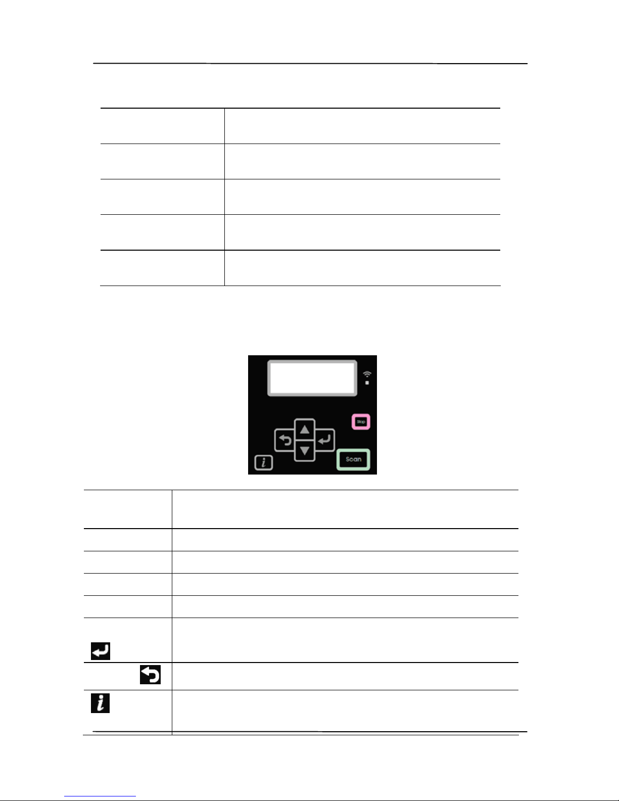
1.4 Operational Panel
LCD
screen
Used to display information and provide access
to the product’s functions.
Wi-Fi LED Used to indicate the Wi-Fi status.
Stop Used to stop an operation.
Scan Used to start a scan.
/ Used to toggle through the menus or options.
Enter
Used to enter a selection.
Back
Used to go back to the previous level.
Used to show to basic system
information.
Page 15

User’s Manual
1-6
1.5 Rear View
Part Name Function
Power Jack Connect the AC adapter to the
scanner.
LAN port Connect the LAN cable to the
scanner for wired network
connection.
WPS button Press to use WPS (Wi-Fi Protected
Setup) to connect to a wireless
access point which supports WPS.
Press the WPS button of your
access point and then press and
hold the WPS button of the
scanner for 5 seconds to start the
WPS connection.
Wi-Fi Switch Turn on or off to enable or disable
the Wi-Fi connection.
USB Port Connect the USB cable to the
scanner.
Kensington
Security Slot
Attach to a lock to secure the
scanner.
Power Jack
LAN Port
WPS Button
USB Port
Kensington
Security
Slot
Wi-Fi Switch
Page 16

User’s Manual
1-7
1.6 Side View
Part Name Function
USB Flash Drive Used to insert a USB flash drive.
USB Flash
Port
Page 17

User’s Manual
1-8
1.7 Pre-installation Checklist
The product has to be setup properly on your network to
perform scan to e-mai
l and scan to network functions. Before
using the product, please setup the product properly on your
network for e-mail and filing function. The following network
parameters have to be set.
1. DHCP Enable:
2. IP Address: . . .
3. Subnet Mask: . . .
4. Gateway IP: . . .
5. DNS Server: . . .
6. WINS Server: . . .
7. SMTP Server:
8. SMTP Port: 25
9. LDAP Server: . . .
10. LDAP Port:
Explanation of contents:
1. *DHCP Enable: Choose Yes to obtain
IP/subnet/gateway/DNS server/WINS
server addresses automatically from
DHCP server.
2. *IP Address: The Internet Protocol (IP) address
assigned to your machine by your
network administrator or by DHCP
server.
3. Subnet Mask:
The net mask address assigned by your
network administrator or by DHCP
server.
4. Gateway IP: The gateway IP address assigned by
your network administrator or by DHCP
server.
Page 18

User’s Manual
1-9
5. *DNS server: The IP address of DNS server assigned
by your network administrator.
6. *WINS Server: The IP address of WINS server
assigned by your network
administrator.
7. *SMTP Server:
The IP address of your SMTP mail
server assigned by your network
administrator.
8. SMTP Port:
The port number of your SMTP Mail
Server.
9. *LDAP Server:
The IP address of your LDAP server.
10. LDAP Port:
The port number of your LDAP server.
Page 19

User’s Manual
1-10
Note:
1. DHCP server: With DHCP (Dynamic Host Configuration
Protocol), a host can automatically be given a unique IP
address each time it connects to a network--making IP
address management an easier task for network
administrators. If the DHCP server is available from your
network, you do not need to enter TCP/IP, subnet mask,
gateway, and DNS information. Instead, this information
will be automatically given for the product.
2. IP Address: An IP (Internet Protocol) address uniquely
identifies a host connection to an IP network. System
administrator or network designer assigns the IP address.
The IP address consists of two parts, one identifying the
network and the one identifying your node. The IP
address is usually written as four numbers separated by
periods. Each number can be zero to 255. For example,
10.1.30.186 could be an IP address.
3. SMTP: Stands for Simple Mail Transfer Protocol. It is the
main communication protocol used to send and receive email on the internet.
4. DNS: Stands for Domain Name System. The DNS server
identifies hosts via names instead of IP addresses. If the
DNS server is available on your network, you can enter
the domain name instead of digits for the IP address.
5. WINS: Stands for Windows Internet Naming Service.
WINS resolves Windows network computer names (also
known as NetBIOS names) to Internet IP addresses,
allowing Windows computers on a network to easily find
and communicate with each other.
6. LDAP: Stands for Lightweight Directory Access Protocol.
LDAP enables users to access directories and address
books directly from external networked devices to
simplify document distribution.
Page 20

User’s Manual
2-1
2. Scanner Installation
2.1 Precautions
Keep the scanner out of direct sunl
ight. Direct exposure
to the sun or excessive heat may cause damage to the
unit.
Do not install the scanner in a humid or dusty place.
Be sure to use the proper AC power source.
Place the scanner securely on an even, flat surface.
Tilted or uneven surfaces may cause mechanical or
paper-feeding problems.
Retain the scanner box and packing materials for
shipping purposes.
Page 21

User’s Manual
2-2
2.2 Connecting to Power
Before connecting, make sure the power switch is off.
Pl
ug the small end of the power adaptor into the power jack of
your scanner. Insert the other end to an appropriate power
outlet.
2.3 Turning on the Power
Press the Power Swi
tch button on the front panel, the Power
LED will flash. When it is finished and ready to scan, the LED
indicator will stop flashing and become steadily on. To turn
off the scanner, press the Power Switch button for about 3
seconds, the Power LED will be off.
Page 22

User’s Manual
2-3
2.4 Connecting to a Network Cable
1. Connect one end of your network cable to an available port
of the swi
tching hub of your LAN.
2. Connect the other end to the LAN port at the back of the
product as shown.
Page 23

User’s Manual
2-4
2.5 Obtaining the Product’s IP Address via DHCP
If you connect the product to your computer vi
a a network
cable, you need to specify an IP address for the product. An IP
address can be obtained automatically through the DHCP server
by default, or you may specify a static IP address via the
product’s embedded web page. Please follow the steps in below
to configure the IP address of the product.
To obtain the product’s IP address via DHCP,
1. Turn on the scanner by pressing the Power button.
2. Press
key on the panel and then choose [Network] on
the LCD screen.
3. The product’s IP address through DHCP server will be
displayed. (Default DHCP) (For example, 10.1.20.25)
<Information>
Scanner
Network
<Wired>
IP Address
10.1.20.25
Page 24

User’s Manual
2-5
2.6 Setting the Product’s Date and Time
To set the product’s date and ti
me,
1. Open your browser and type the product’s IP address on the
URL field to prompt the product’s embedded web page.
To access complete information of the web page, please
login with the default user name and password – [admin].
The password can be changed later in the web page.
2. Choose [Device Management]>[General], and then
revise current date and time. Or specify your NTP server.
4. Click [Update] to save the setting and exit the page.
Device
Management
Page 25

User’s Manual
2-6
2.7 Specifying the Product’s Mail Server
To use the scan-to-email feature, you must specify the product’s
SMTP server or LDAP server i
f you wish to import an address
book from other devices.
To specify the SMTP and LDAP server,
1. On the product’s web page, choose [Network]>[Mail
server] option to prompt the [Mail server] page.
2. Enter your mail server information. Enter authentication
information if required. (See the follow in g screen as an
example.)
E-mail Server Setting
Mail Server Enter the IP address of your SMTP server.
SMTP Port # Enter the port number of the SMTP server.
* 25
Device Email Address
Enter the device’s e-mail address. If the [From]
address has not been set in the E-Mail setting,
this address will be shown as the [From]
address from outgoing mails.
Authenticati
on Method
Enter the email authentication method.
Choice: *None, SMTP, POP3
Encrypt Choose the encryption method of your emails
to the SMTP server.
Choice: *None, STARTTLAS, SSL/TLS
Mail
Server
Page 26

User’s Manual
2-7
Login Name Enter the login name for SMTP
authentication.
Password Enter the password for SMTP authentication.
LDAP Server Setting
LDAP Server IP
or URL
Enter the IP address or the URL of your
LDAP server.
Port # Enter the port number of the LDAP server.
* 389
Login Name Enter the login name of the LDAP server.
Note:
1. In Microsoft Active Directory, some
servers may require you to add “domain
name” as your full login name. For
example, if your domain name is
“company” and your user name is
“administrator”, then your full login
name is “company\administrator”.
2. When your LDAP server requests an
“anonymous login”, please leave your
login name and password blank instead
of typing “anonymous” as your login
name and password.
Password Enter the password of the LDAP server.
Search Root Enter your base DN. Base DN (distinguished
name) identifies the starting point of a
search. A dn indicates what record to view
in an LDAP tree. The top level of the LDAP
directory tree is the base, referred to as the
"base DN". For example, you could indicate
a base of dc=com,dc=net for a search that
starts at the top and proceeds downward.
Search
Attribute
cn
Obtain E-Mail
Address From
mail
Timeout(secon
d)
The specified time to connect the LDAP
server.
Authentication
Type
Choice: Anonymous, Simple
Page 27

User’s Manual
2-8
Note: Please check the SMTP server and LDAP server
information with your Network Administrator.
3. Click [Update] to save the setting and exit the page.
Note:
1. The login name is case-sensitive and is up to 32 digits
or characters.
2. The password is case-sensitive and is up to 16
characters.
3. LDAP Search:
This machine supports two types of authentication,
simple and anonymous, to login your LDAP servers.
This machine allows up to 100 match results in a single
search.
The attributes such as “cn” and “mail” have been
predefined as the search field. Therefore, if your
search text is “m”, the LDAP search engin e will search
the name or the email address that contains the
character “m”. For example, you might get the return
match results such as “mary, [email protected]”, or “jack,
[email protected]”.
Page 28
User’s Manual
3-1
3. Setting Up and
Managing Destinations
This section provides procedure for the administrator to setup
and manage destinations including e-mail addresses or netw ork
folders to distribute the scanned document on the network.
3.1 Setting Up Your E-Mail Address Book
T
o create an E-Mail Profile, you must first setup your E-Mail
Address Book. This section provides procedure for the
administrator on how to setup E-Mail Address Book.
3.1.1 Adding A New E-Mail Address
Follow these steps to setup your Address Book.
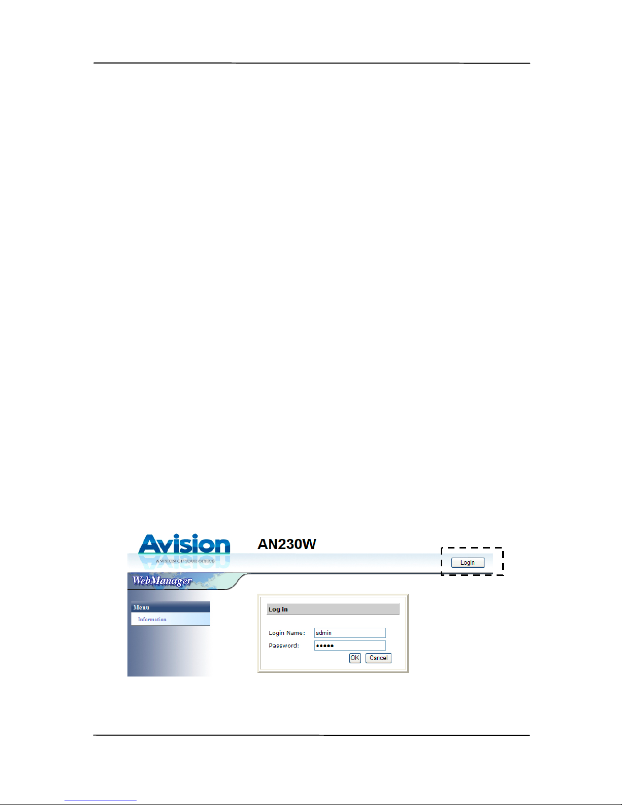
1. Open your browser and type the product’s IP address on
the URL field to prompt the product’s embedded web page.
To access complete information of the web page, please
l
ogin with the default user name and password – [admin].
The password can be changed later in the web page.
2. Choose [Address Book] to prompt the [Address Book]
page.
Page 29

User’s Manual
3-2
3. On the [E-Mail List] tab, choose [New] to prompt the
[Add a New E-Mail Address] page.
4. Enter your E-Mail address and its description.
5. Edit your address information. Click [Submit] to save the
setting or [Quit] to leave the page without saving any
setting.
Note:
Up to 200 e-mail addresses can be entered in the Address
Book.
3.1.2 Deleting A Current E-Mail Address
To delete a current e-mail address,
1. Repeat Step 1 to Step 2 from the previous section, Adding
a New E-Mail Address. The [Address Book] page
appears.
Page 30

User’s Manual
3-3
2. Choose the address you want to delete from the list and
then choose [Delete] to erase the address. A
Confirmation dialog box appears to confirm your deletion.
Click [OK] to confirm or [Cancel] to exit.
3.1.3 Editing A Current E-Mail Address
To Edit a current e-mail address,
1. Repeat Step 1 to Step 2 from the previous section, Adding
a New E-Mail Address. The [Address Book] appears.
2. Choose the address you want to Edi
t from the list and then
choose [Edit] to prompt the [Edit E-Mail Addresses]
page.
3. Edit your address information. Click [Submit] to save the
setting or [Quit] to leave the page without saving any
setting.
3.1.4 Adding A New E-Mail Group
T
o send multiple addresses simultaneously at one time, y ou
can create address group to speed up the process. Up to 20
addresses can be included in one group and a total of 20
groups can be created in the Address Book.
1. Repeat Step 1 to Step 2 from the previous section, Adding
a New E-Mail Address. The [Address Book] appears.
2. Click [Group List] and then choose [New] to prompt the
[Add a New Group] page.
3. Enter your group name and its description.
4. Choose the address from the right side and click to add
a member to the group.
5. Click [Submit] to save the setting or [Quit] to leave the
page without saving any setting.
Page 31

User’s Manual
3-4
3.1.5 Deleting A Current E-Mail Group
To delete a current e-mail group,
1. Repeat Step 1 to Step 2 from the previous section, Adding
a New E-Mail Address. The [Address Book] appears.
2. C
lick [Group List] and choose the group you want to
delete from the list and then choose [Delete] to erase the
group. A Confirmation dialog box appears to confirm your
deletion. Click [OK] to confirm or [Cancel] to exit.
3.1.6 Editing A Current E-Mail Group
T
o Edit a current e-mail group,
1. Repeat Step 1 to Step 2 from the previous section, Adding
a New E-Mail Address. The [Address Book] appears.
2. Click [Group List] and choose the group you want to Edit
from the list and then choose [Edit] to prompt the [Edit
E-Mail Group] page.
3. Edit your group information. Choose the group member
you wish to add and then click to add the new member
or click to delete an old member from the group.
4. Click [Submit] to save the setting or [Quit] to leave the
page without saving any setting.
Page 32
User’s Manual
3-5
3.1.7 Importing An E-Mail Address Book
To import an e-mail address book,
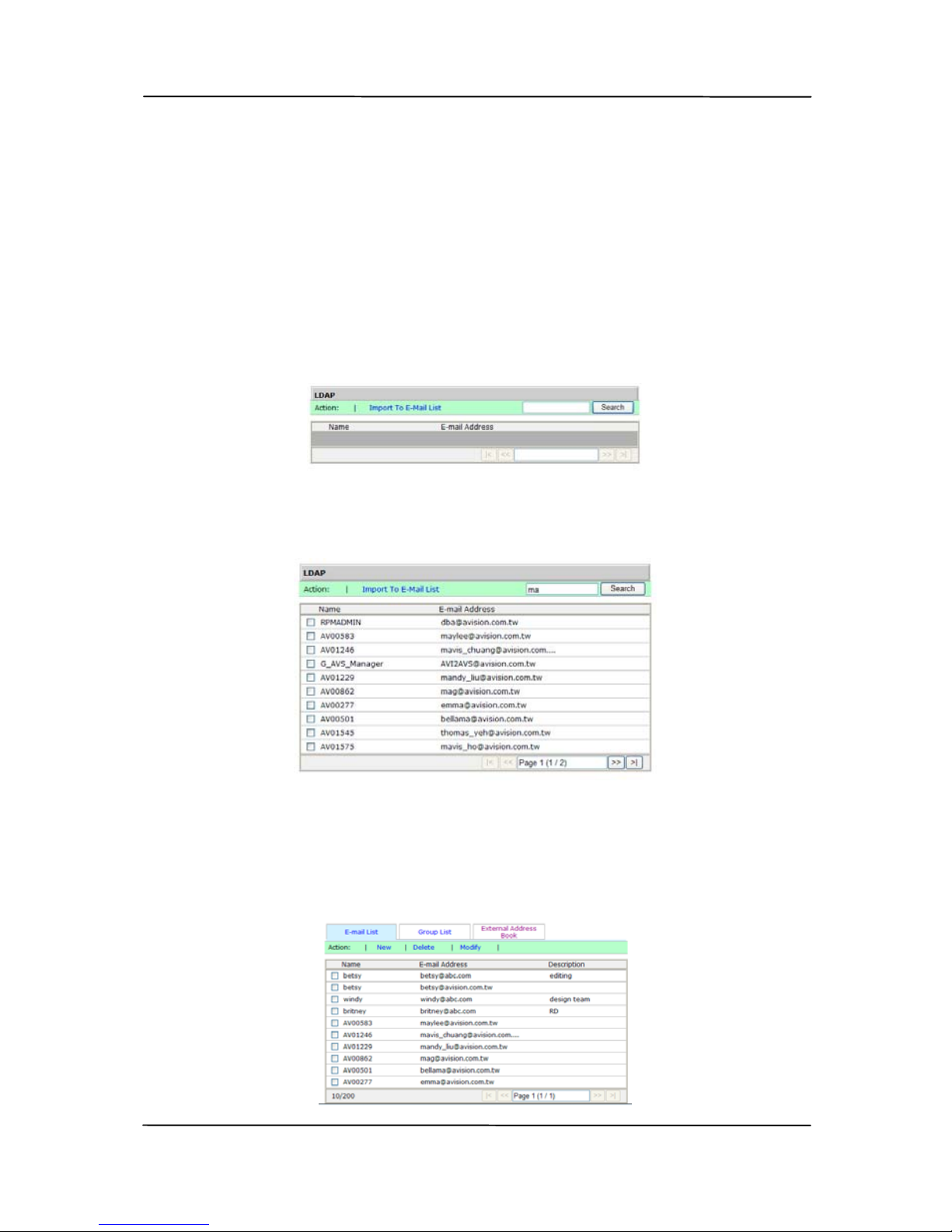
1. Repeat Step 1 to Step 2 from the previous section, Adding
a New E-Mail Address. The [Address Book] appears.
2. C
lick [External E-Mail Address Book] to prompt the
[LDAP] page.
3. Enter your search key word, for example, ma.
4. In a second, the search result will be displayed.
5. Choose the e-mail address which you want to import to
the device and click the [Import to E-Mail List] tab.
6. The selected e-mail addresses will be imported and
included in your E-Mail list as shown in below.
Page 33
User’s Manual
3-6
3.2 Setting Up Your E-Mail Profiles
T
his section provides procedures to setup your e-mail profile to
send the scanned document to your recipients.
3.2.1 Adding A New E-Mail Profile
T
o create an E-Mail Profile, follow these steps:
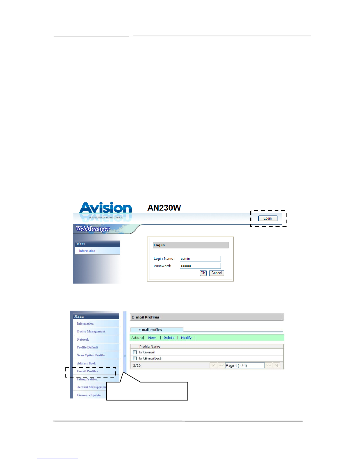
1. Open your browser and type the product’s IP address on
the URL field to prompt the product’s embedded web page.
To access complete information of the web page, please
login with the default user name and password – [admin].
The password can be changed later in the web page.
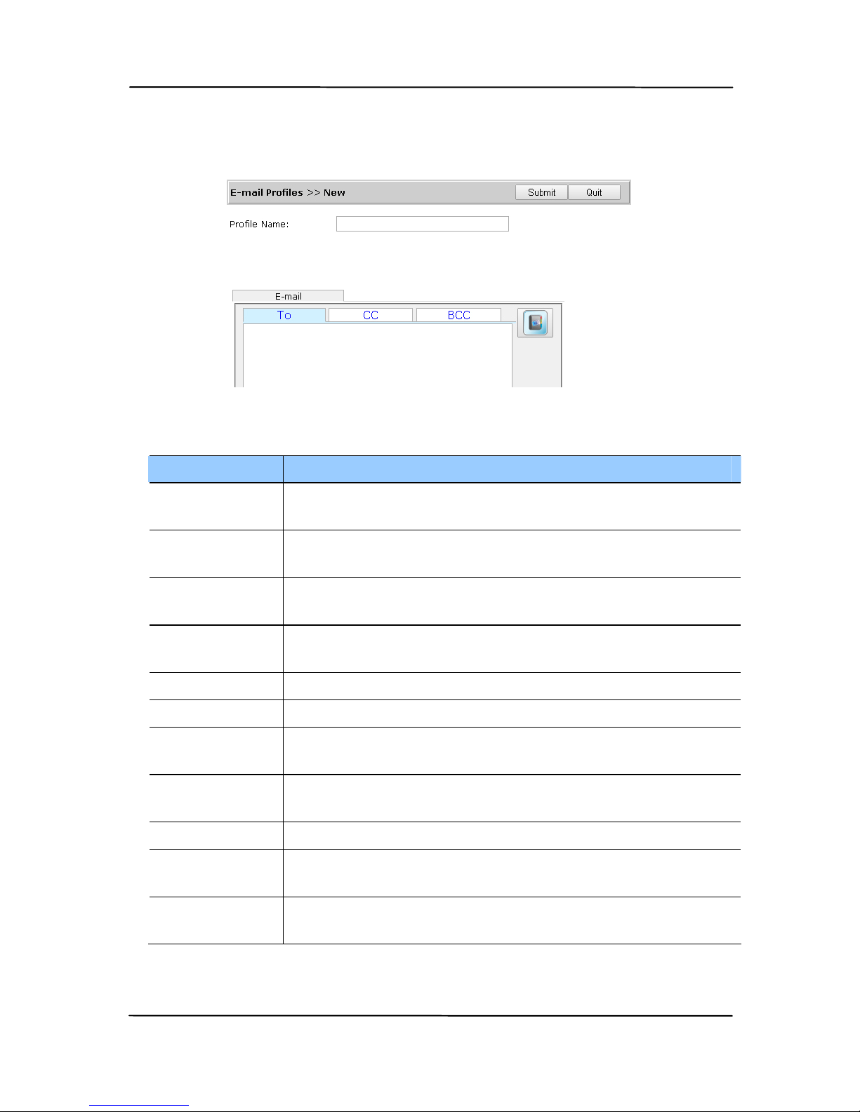
2. Choose [E-Mail Profiles] to prompt the following page.
E-Mail Profiles
Page 34
User’s Manual
3-7
3. Choose [New] to prompt the [Add a New E-Mail Profile]
page.
Enter the following information respectively:
Item Description
Profile
Name
Enter the name of your profile. The name will be
shown in the LCD screen.
To Select the recipient’s e-mail address from the
Address Book.
CC Select the CC e-mail address from the Address
Book.
BCC Select the BCC e-mail address from the Address
Book.
Subject Type your subject.
File Name Enter the file name of your attachment.
From Select the sender’s e-mail address from the
Address Book.
Reply to
Address
Select the e-mail address you wish to reply to.
Text Type your email message here.
File
Separation
Choice: 1MB/3M/5M/10M/30MB/Unlimited
Scan Option
Profile
Choose your scan option profile. (*Default)
4. Click [Submit] to save the setting and exit the page.
Page 35

User’s Manual
3-8
3.2.2 Deleting A Current E-Mail Profile
T
o delete a current e-mail profile,
1. Repeat Step 1 to Step 3 from the previous section, Adding
a New E-Mail Profile. The [E-Mail Profiles] page appears.
2. Choose the E-Mail Profile you want to delete from the list
and then choose [Delete] to erase the profile. A
Confirmation dialog box appears to confirm your deletion.
Click [OK] to confirm or [Cancel] to exit.
3.2.3 Editing A New E-Mail Profile
T
o Edit a current e-mail group,
1. Repeat Step 1 to Step 3 from the previous section, Adding
a New E-Mail Profile. The [E-Mail Profiles] page appears.
2. Choose the E-Mail Profile you want to Edit from the list
and then choose [Edit] to prompt the [Edit E-Mail
Profile] page.
3. Edit your profile information.
4. Click [Submit] to save the setting or [Quit] to leave the
page without saving any setting.
Page 36
User’s Manual
3-9
3.3 Setting Up Your Filing Profile
T
he section provides procedure on how to setup your f iling
profile to send your scanned document to the specified
network.
3.3.1 Adding A New Filing Profile
T
o create a Filing Profile, follow these steps:
1. Open your browser and type the product’s IP address on
the URL field to prompt the product’s embedded web page.
To access complete information of the web page, please
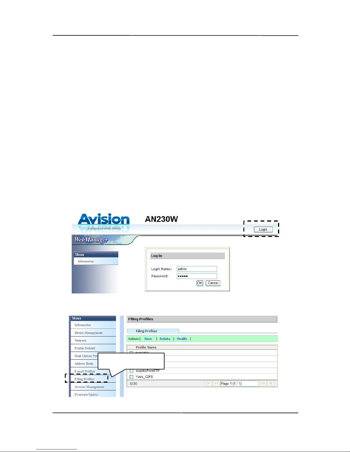
login with the default user name and password – [admin].
The password can be changed later in the web page.
2. Choose [Filing Profile] to prompt the following page.
Filing Profiles
Page 37
User’s Manual
3-10
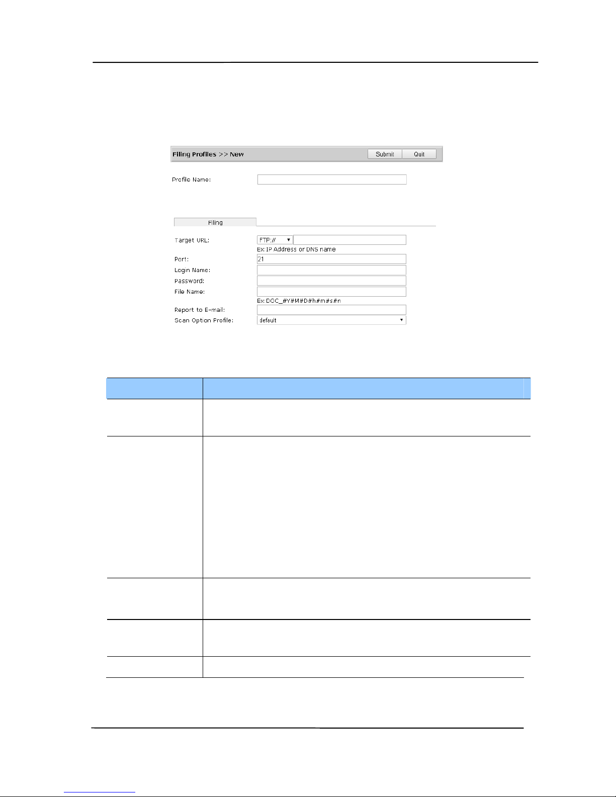
3. Choose [New] to prompt the [Add a New Filing Profile]
page.
Enter the following information respectively:
Item Description
Profile
Name
Enter the name of your profile. The name will
be shown in the LCD screen.
Target
URL
Enter the IP address and the shared folder
name of your FTP server.
FTP: If you have not established a folder in
the FTP server, please do not enter the folder
name in the URL address.
CIFS: You must set a folder in the CIFS
server or your scanned image may not be
uploaded successfully.
Port # Enter the port number of the filing serv er.
* 21 (FTP), 139 (CIFS)
Login
Name
Enter the user name of the filing server.
Password Enter the password of filing server.
Page 38

User’s Manual
3-11
File Name Enter your desired prefix for the file name.
Naming Method:
Prefix_YYMMDDHHMMSS_xxx.file format.
For example,
「DOC_150213144840_001.pdf」
indicates 2015 (year) 2 (February) 13
(date) 14 (hour) 48 (minute) 40 (second)
001 (serial number)
Report to
E-mail
Enter an e-mail address if you wish to send
the filing report to the e-mail.
Scan
Option
Profile
Choose your desired scan option profile.
4. Click [Submit] to save the setting or [Quit] to leave the
page without saving any setting.
Page 39

User’s Manual
3-12
3.3.2 Deleting A Current Filing Profile
T
o delete a current filing profile,
1. Repeat Step 1 to Step 3 from the previous section, Adding
a New Filing Profile. The [Filing Profile] page appears.
2. Choose the Filing Profile you want to delete from the list
and then choose [Delete] to erase the profile. A
Confirmation dialog box appears to confirm your deletion.
Click [OK] to confirm or [Cancel] to exit.
3.3.3 Editing A New Filing Profile
T
o Edit a current filing profile,
1. Repeat Step 1 to Step 3 from the previous section, Adding
a New Filing Profile. The [Filing Profile] page appears.
2. Choose the Filing Profile you want to Edit from the list and
then choose [Edit] to prompt the [Edit Filing Profile]
page.
3. Edit your profile information.
4. Click [Submit] to save the setting or [Quit] to leave the
page without saving any setting.
Page 40

User’s Manual
4-1
4. Operation
4.1 Loading Your Paper
4.1.1 Notice on Using the ADF
Before using the ADF, please make sure that your paper meets
t
he following specifications:
Document(s) can range in size from 50 x 50 mm (2 x 2
in.) to 216 x 356 mm (8.5 x 14 in.).
Document(s) can range in weight from 27 ~ 413 g/m
2
(7
~ 110 lb.)
ID cards up to 1.25 mm (0.05 in.) thick
Document(s) should be square or rectangular and in good
condition (not fragile or torn).
Document(s) should be free of curl, wrinkle, wet ink, or
punch holes.
Document(s) should be free of staples, paper clips, paper
sticky notes.
Page 41
User’s Manual
4-2
4.1.2 Loading Your Document in the ADF Paper Tray
Fanning Your Document
Note:
To avoid occasional multi-feeds or paper jams, please fan
your documents and align the top edges before feeding them
into the scanner.
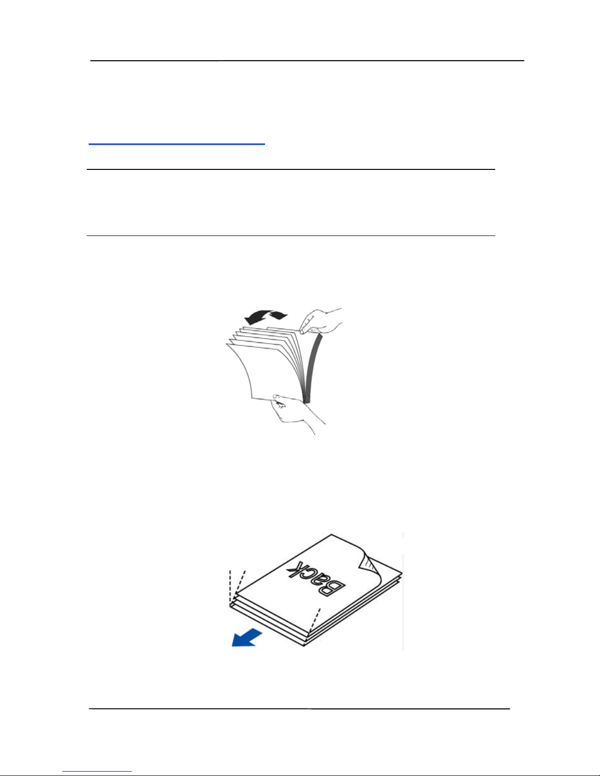
1. Hold both ends of the documents and fan them a few
times.
2. Rotate the documents by 90 degrees and fan them in the
same manner.
3. Align the edges of the documents in a step-like pattern
(see picture below).
Step-like
Scanning
Direction
Page 42
User’s Manual
4-3
Document Feeding
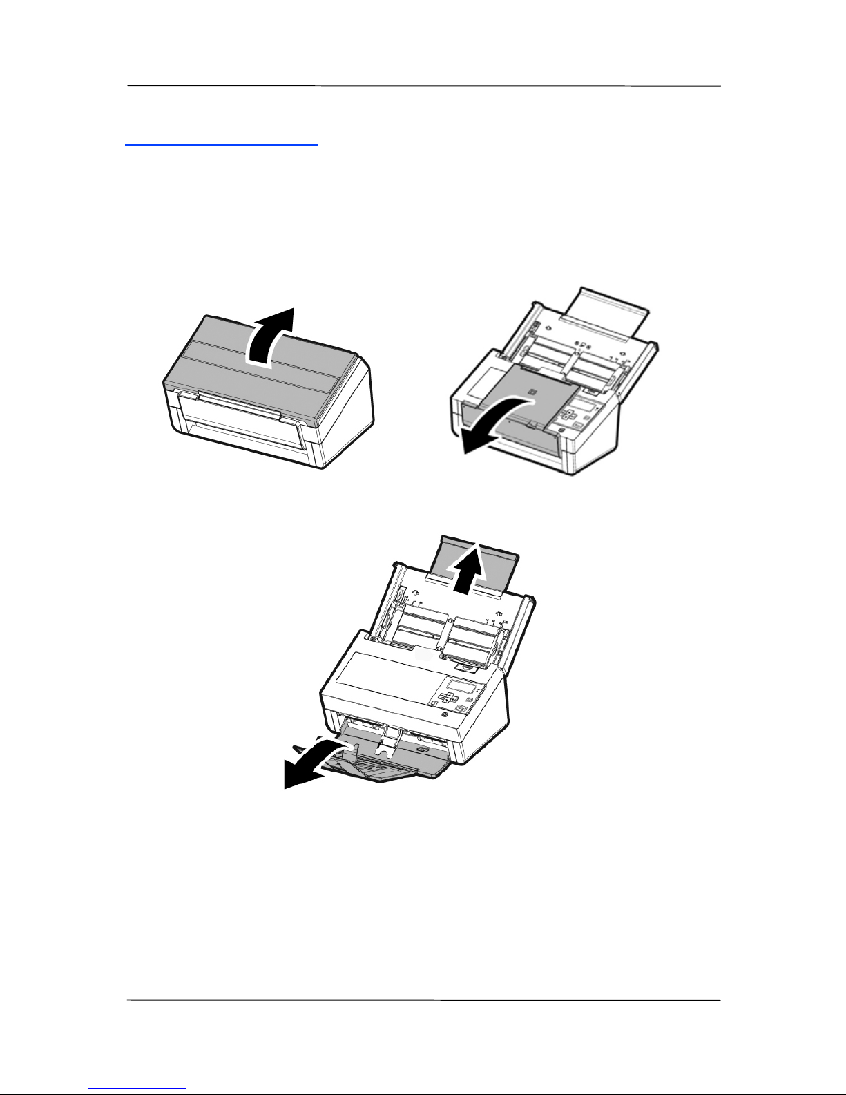
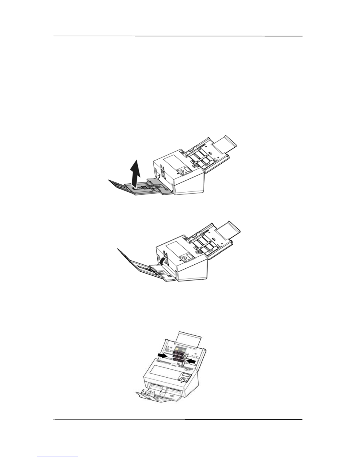
1. Unfold the document feeder and its extension.
2. Unfold the output tray and raise the paper stopper.
Page 43
User’s Manual
4-4
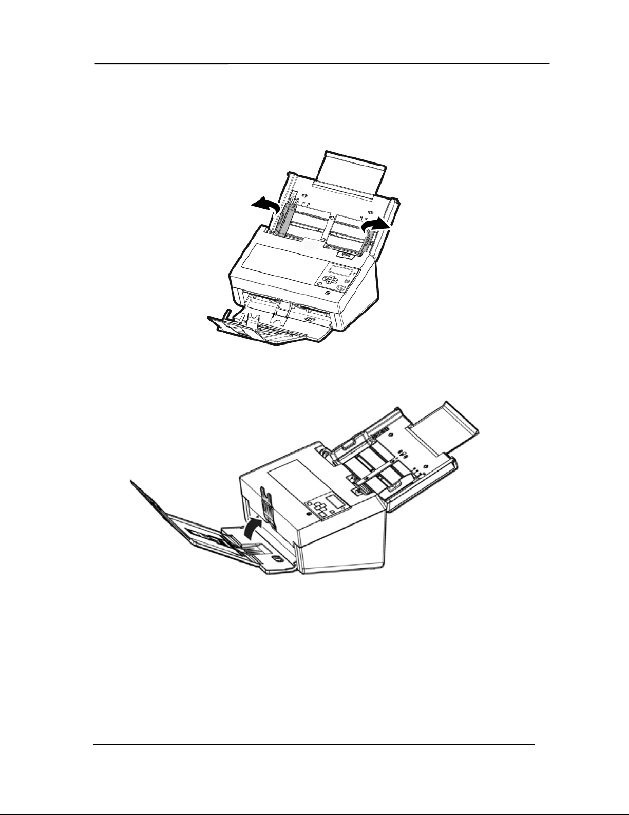
3. Raise the paper guide to hold your multi-page
document.
4. Raise the paperweight.
Page 44
User’s Manual
4-5
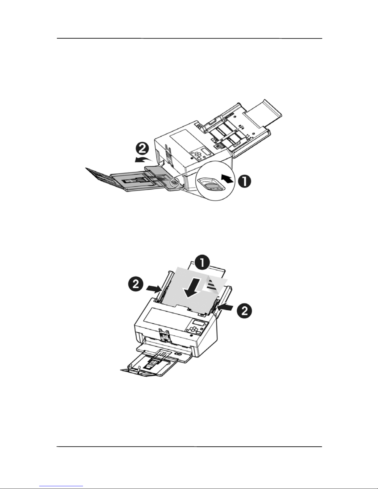
5. Slide the position adjustor inward
to make the output
tray in a flat position
.
6. Load a stack of document face down with the top of the
pages pointing into the feeder.
7. Verify that the paper guides are aligned with the edges
of the stack.
Page 45
User’s Manual
4-6
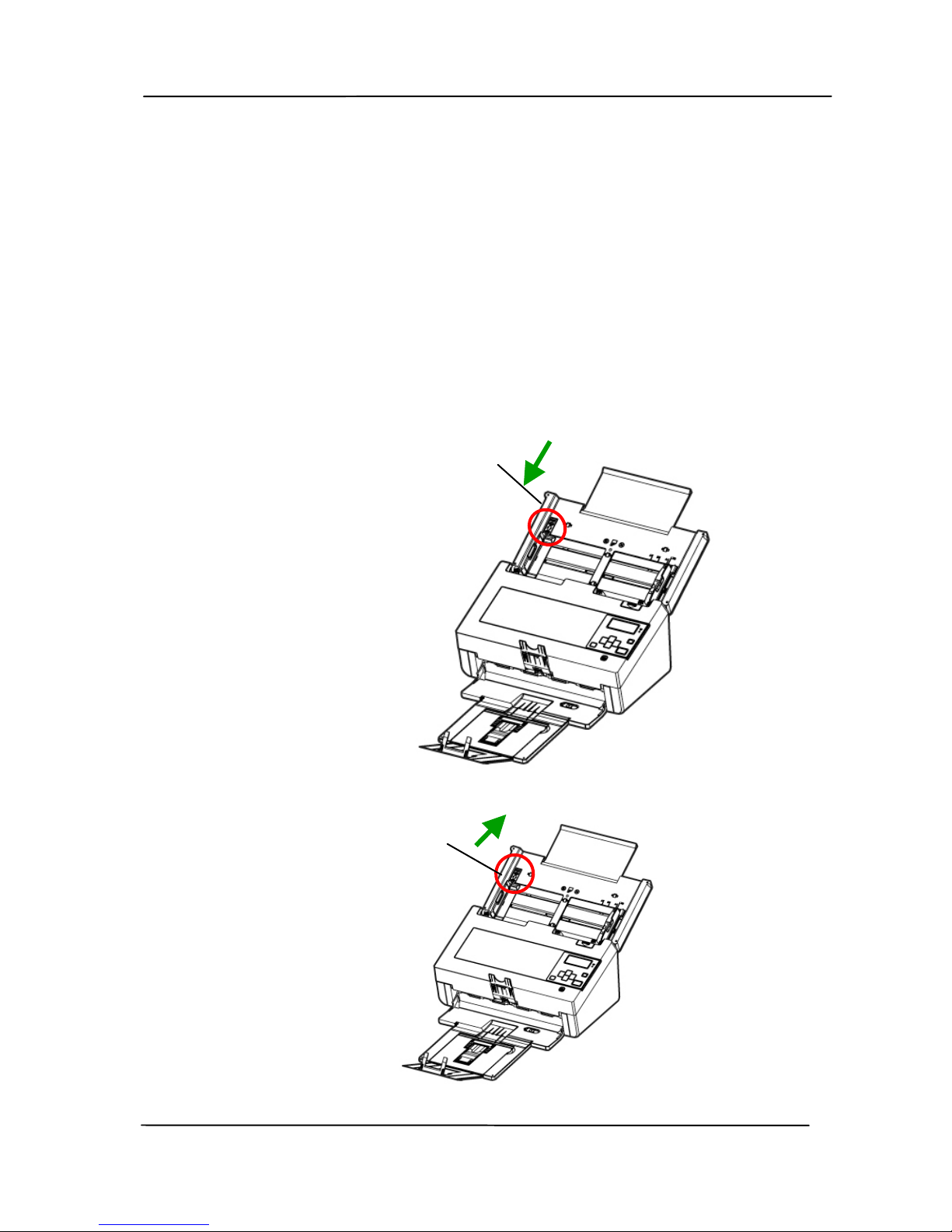
Note: The [Paper Width] switch:
If your document width is 216 mm (8.5 in.):
If your document width is 216 mm (8.5 in.), slide the
[Paper Width] switch DOWN to fix your paper guide to
conveniently load the letter-size document.
If your document width is larger than 216 mm (8.5 in.):
If your document width is larger than 216 mm (8.5 in.)
such as invoices with punch holes, slide the [Paper
Width] switch UP and move the paper guide to the right
end to load your documents.
Slide DOWN the [Paper
Width] switch to set your
paper width to 216 mm
(8.5 in.)
Slide UP the [Paper
Width] switch to set
your paper width larger
than 216 mm (8.5 in.)
Page 46
User’s Manual
4-7
4.1.3 Scanning Cards
To scan cards, it is recommended to press down the paper
wei
ght and then raise the output tray to keep the cards from
falling apart.
1. Lift the output tray up to make the output tray in an
angled position.
2. Press down the paper weight.
3. Load your cards horizontally into the paper tray. Align
the paper guides and make sure the edges of cards
slightly touch the paper guides on both side as
illustrated.
8B
Page 47
User’s Manual
4-8
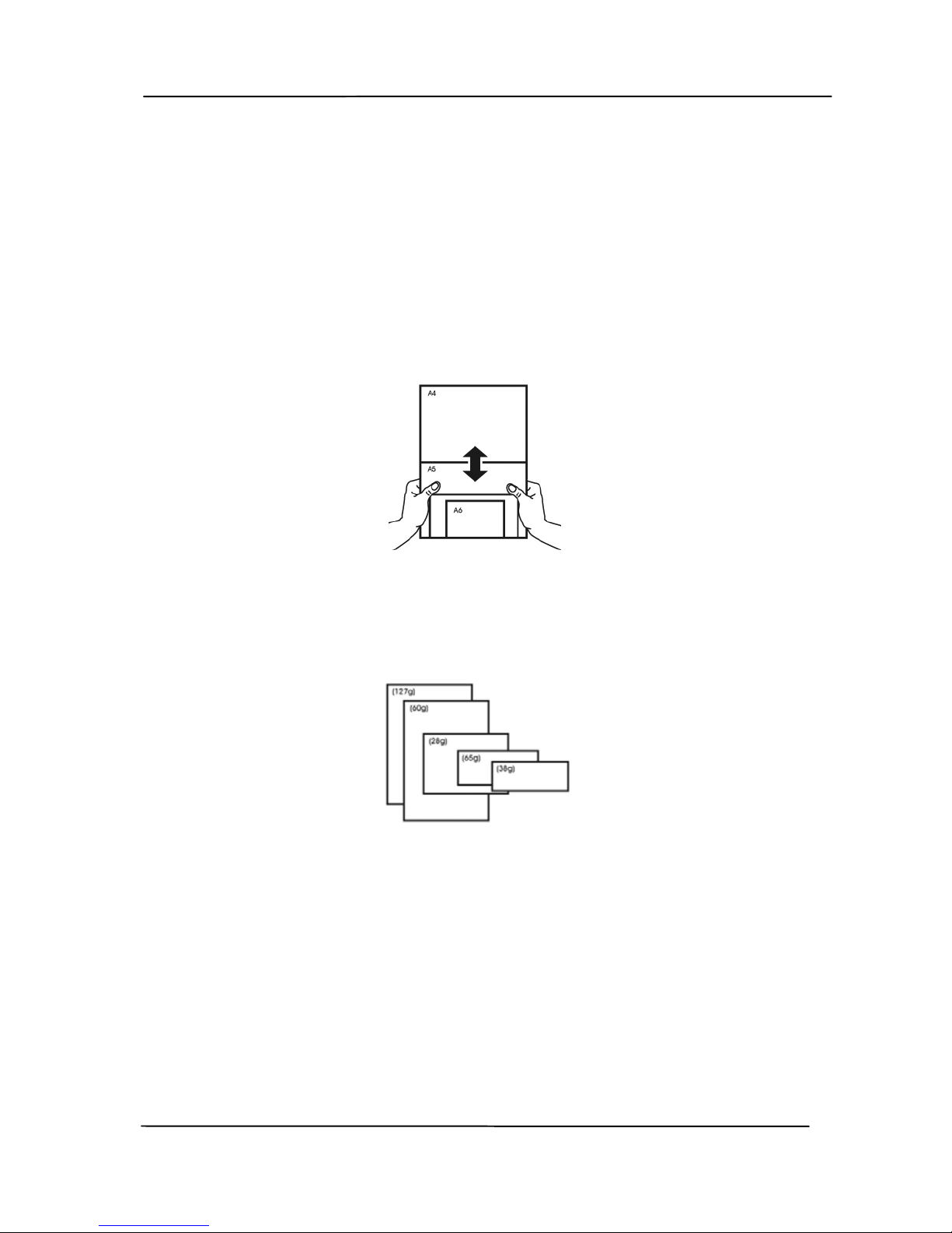
4.1.4 Scanning a Stack of Document with Various sizes
and Weights
When scanning a batch of documents with different sizes and
weights, be sure to follow these guidelines to avoid a skewed
image or a paper jam:
1. Align the documents TOP EDGE first in the sequence of
paper size from large to small.
2. If two pages are of the same size yet with different weight,
arrange these pages in the sequence of paper weight from
heavyweight to lightweight.
Page 48
User’s Manual
4-9
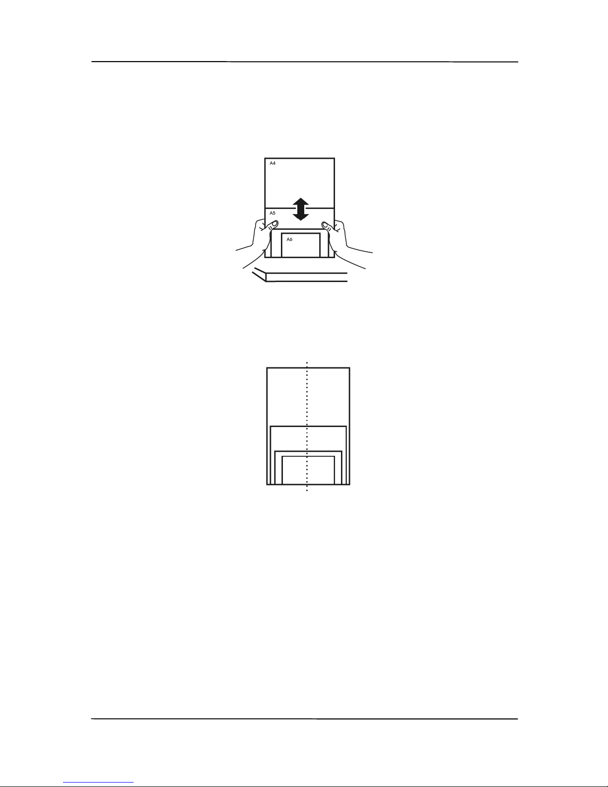
3. Align the edges of the documents by tapping the bottom of
the stack against the table top.
4. Center these pages in the document feeder and make sure
that the edges of page of the largest size slightly touch the
Paper Guide.
Page 49
User’s Manual
4-10
4.2 Scanning and Sending Your Scanned Image to E-
Mail
Before You Begin:
Before scanning and sending your scanned image as an
attachment to your e-mail, make sure you have setup your email profile first as described in the preceding section, 3.2
Setting up Your E-Mail Profile.
To start a scan and send the scanned image as an attachment
to your E-mail,
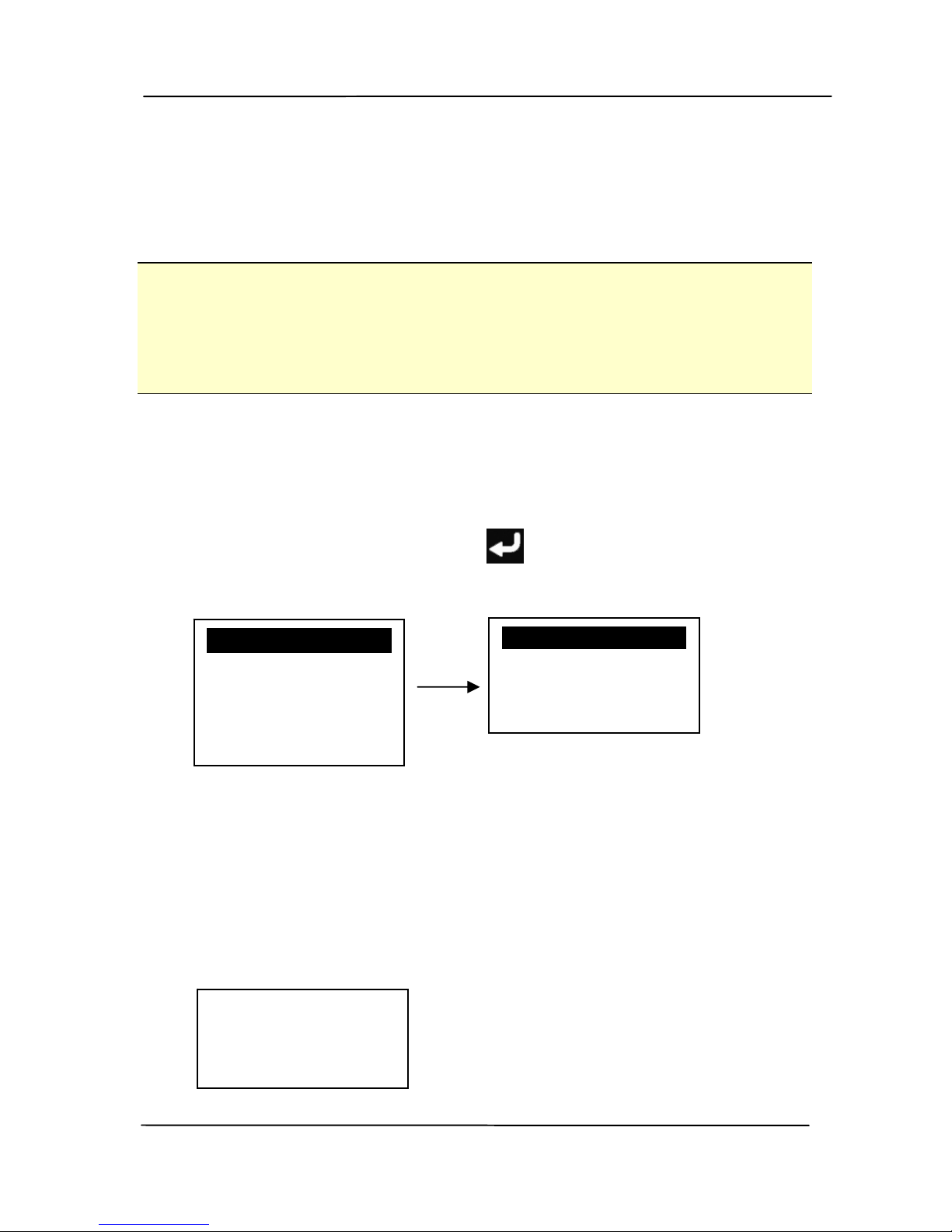
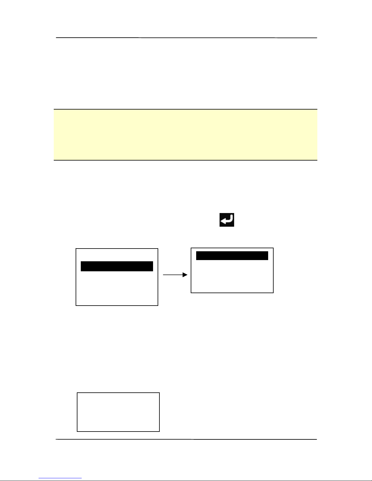
1. Use / to scroll to [Email Profiles] on the LCD display
and then press the [Enter]
key. The current E-Mail
profile will be shown.
2. Choose the E-mail profile you wish to send the scanned
image to.
3. Press the [Scan] button to start a scan.
4. The scanner starts feeding your document and sends the
scanned image to your E-mail.
E-Mail Profiles
Filing Profiles
Scan to USB
Scan to PC
AP Mode
E-Mail Profile 1
E-Mail Profile 2
E-Mail Profie 3
E-Mail Profile
Scanning
Page 1
Page 50
User’s Manual
4-11
4.3 Scanning and Sending Your Scanned Image to a
Network Folder
Before You Begin:
Before scanning and sending your scanned image to a network
folder, make sure you have setup your e-mail profile first as
described in the preceding section, 3.3 Setting up Your Filing
Profile.
To start a scan and send the scanned image to a network
folder,
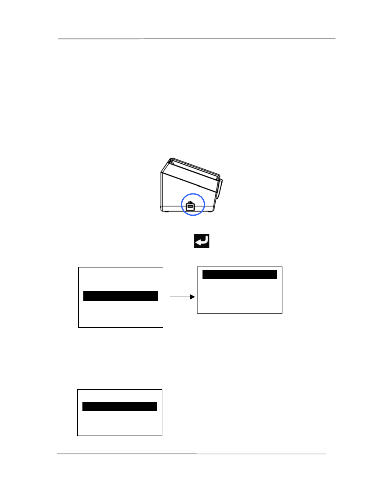
1. Use to scroll down to [Filing Profiles] on the LCD
display and then press the [Enter]
key. The current
Filing profile will be shown.
2. Choose the Filing profile you wish to send the scanned
image to.
3. Press the [Scan] button to start a scan.
4. The scanner starts feeding your document and sends the
scanned image to a specified network folder.
E-Mail Profiles
Filing Profiles
Scan to USB
Scan to PC
AP Mode
Filing Profile 1
Filing Profile 2
Filing Profile 3
Filing Profile
Scanning
Page 1
Page 51
User’s Manual
4-12
4.4 Scanning and Sending Your Scanned Image to a USB
Flash Drive
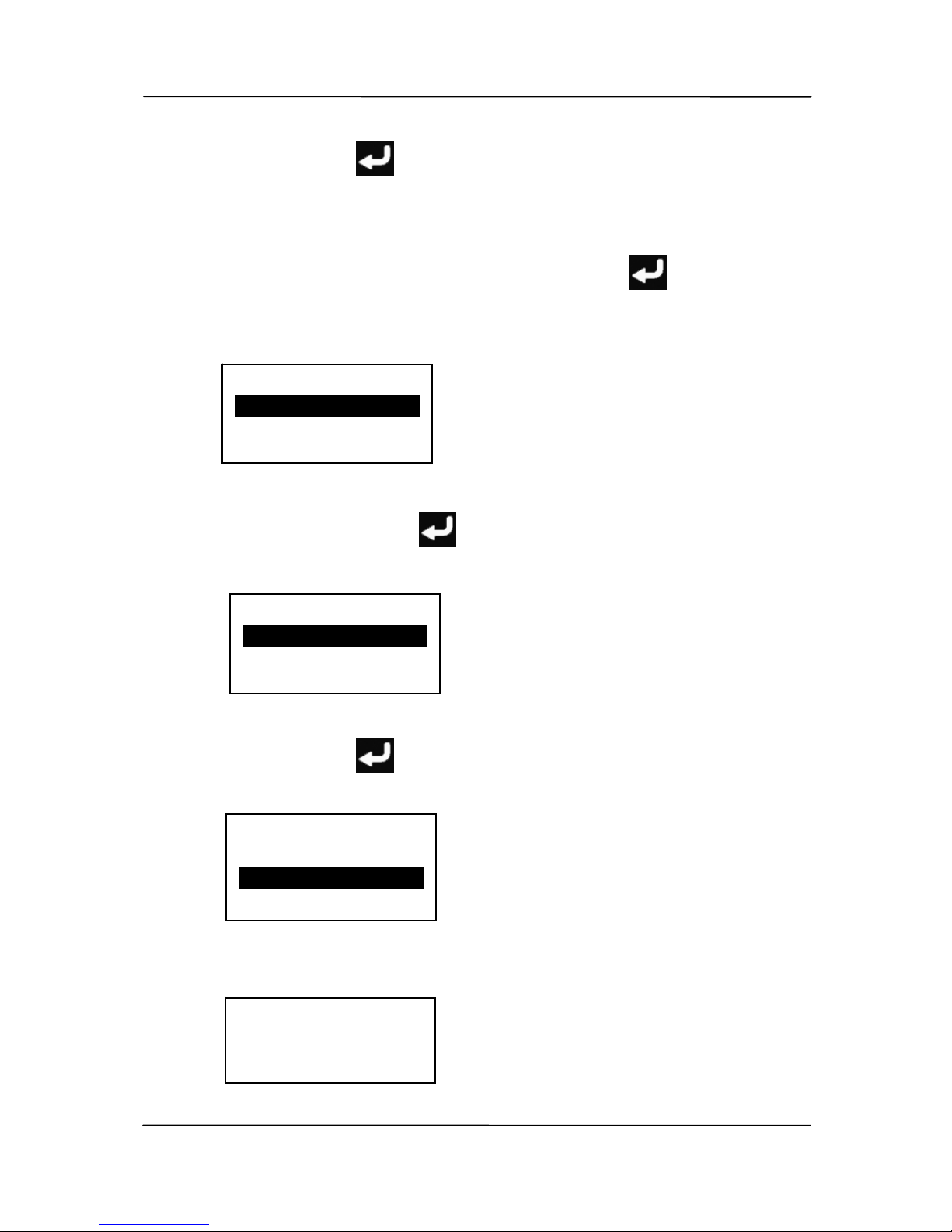
To start a scan and send the scanned image to an inserted USB
fl
ash drive,
1. Insert a USB flash drive to the flash drive port on the left
side of the scanner.
2. Use to scroll down to [Scan to USB] on the LCD display
and then press the [Enter]
key. The current scan
profile will be shown.
3. Choose your desired scan profile from the list.
Or choose [default] to check and select your desired scan
settings respectively.
E-Mail Profiles
Filing Profiles
Scan to USB
Scan to PC
AP Mode
default
scan profile 1
invoice
<Paper Size>
A4
Letter
Legal
Page 52
User’s Manual
4-13
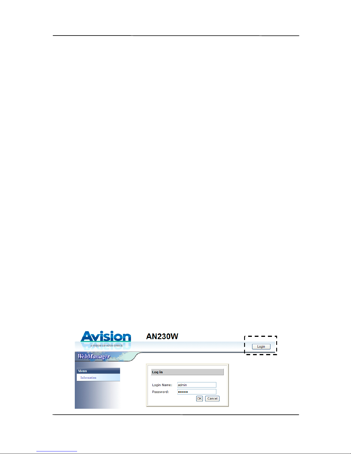
a. Use to select your desired paper size and then press
the [Enter]
key to go to the next item. Choice:
*A4, Letter, Legal, 4x6, 5x7, Auto. (*: default)
b. Use to select to scan one side or two sides of your
document and then press the [Enter]
key to go to
the next item. Choice: *Simplex (1-Sided), Duplex (2Sided) (*: default)
c. Use to select your desired color mode and then
press the [Enter]
key to go to the next item.
Choice: *Color, Gray (*: default)
d. Use to select your desired resolution and then press
the [Enter]
key to start a scan. Choice: 150 dpi,
200 dpi, *300 dpi, 600 dpi (*: default)
e. The scanner starts feeding your document and sends
the scanned image to your USB flash drive.
<Scan Size>
Simplex
Duplex
<Color Mode>
Color
Gray
<Resolution>
200 dpi
300 dpi
600 dpi
Scan to USB
Scanning
Page 1
Page 53
User’s Manual
5-1
5. Setting up and Managing
Your Scan Settings for the
Product
The product allows you to set various scan settings to fit your
different scanning task. The scan settings include basic image
processing settings, such as, color/grayscale/black and white,
output file format, resolution, paper size, one-sided or twosided.
5.1 Editing Your Scan Option Profiles
T
his section provides procedure for the administrator on how to
setup the scan option profiles to fit a variety of scanning tasks.
5.1.1 Adding A New Scan Option Profile
To add a new scan option profile,
1. Open your browser and type the product’s IP address on
the URL field to prompt the product’s embedded web page.
To access complete information of the web page, please
l
ogin with the default user name and password – [admin].
The password can be changed later in the web page.
Page 54
User’s Manual
5-2
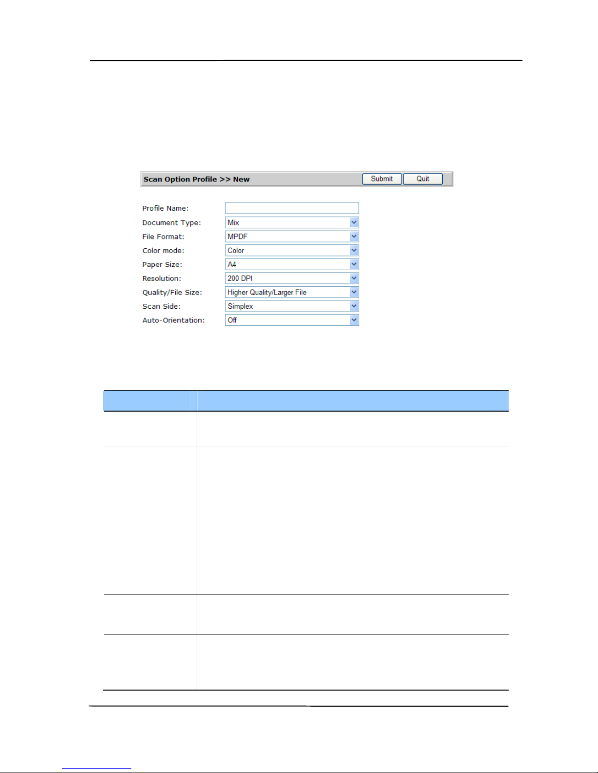
2. Choose [Scan Option Profile] to prompt the [Scan
Option Profile] page.
3. Choose [New] to prompt the [Add a New Scan Option
Profile] page.
Refer to the following table to choose your selection
respectively:
Item Description
Profile
Name
Enter the name of your profile.
Document
Type
Choose your document type.
Choice: *Mixed, Photo, Document
Text: Suitable for document contains pure
text.
Photo: Suitable for document contains
photos.
Mixed: Suitable for common business
document with photo or text.
File
Format
Choose your desired file format.
Choice: JPEG, TIFF, MTIFF, PDF, *MPDF
Color
Mode
Choose your desired color mode.
Choice: *Color, Grayscale, Black and
White
Page 55

User’s Manual
5-3
Paper Size
Choose your desired paper size.
Choice: Auto, 4x6, 5x7, *A4, Letter,
Legal
Resolution Choose your desired resolution for your
scanning task.
Choice: 150 dpi, *200 dpi, 300 dpi, 600
dpi
Scan Side Choose to scan 1-Sided or 2-Sided
document.
Choice: *Simplex (1-Sided), Duplex (2Sided).
* default
4. Click [Submit] to save the setting or [Quit] to leave the
page without saving any setting.
5.1.2 Deleting A New Scan Option Profile
To delete a current scan option profile,
1. Repeat Step 1 to Step 3 from the previous section, Adding
a New Scan Option Profile. The [Scan Option Profile]
page appears.
2. Choose the scan option profile you want to del
ete from the
list and then choose [Delete] to erase the profile. A
Confirmation dialog box appears to confirm your deletion.
Click [OK] to confirm or [Cancel] to exit.
Page 56

User’s Manual
5-4
5.1.3 Editing A New Scan Option Profile
To Edit a current scan option profile,
1. Repeat Step 1 to Step 3 from the previous section, Adding
a New Scan Option Profile. The [Scan Option Profile]
page appears.
2. Choose the scan option profile you want to Edit from the
l
ist and then choose [Edit] to prompt the [Edit Scan
Option Profile] page.
3. Edit your profile information.
4. Click [Submit] to save the setting or [Quit] to leave the
page without saving any setting.
Page 57
User’s Manual
6-1
6. Configuring the Product
The section provides procedure to configure system
information, specify your net w ork settings, create address
book, set E-mail or Filing profile, update firmware, and
export/import system data.
6.1 Configuring the Product’s Device Management
Information
6.1.1
Configuring the Product’s General Information
To change the product’s general information:
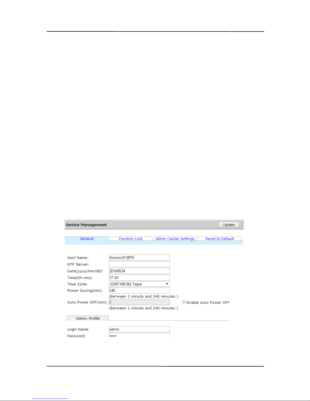
1. On the product’s web page, choose [Device
Management]>[General] to prompt the [General]
page.
Page 58

User’s Manual
6-2
3. Refer to the following table to change the product’s
general information.
Item Description
Host Name
Avision-xxxxxx: The host name for the
scanner in a wired and wireless
environment. Xxxxxx indicates the last six
digits of the scanner’s Mac address.
NTP Server
Used to specify the product’s NTP server.
Date Used to specify the product’s current date.
Time Used to specify the product’s current time.
The time format is 24-hour system.
Time Zone Used to specify the time zone of your
location.
Power
Saving
Used to specify how long the product needs
to enter the power saving mode after last
action. Range: 1 ~ *240 minutes
Auto Power
OFF
Used to specify how long the product needs
to shut down automatically after last action.
Range: 1 ~ 480 minutes
Enable Auto
Power Off
Check to enable auto power off.
Admin Profile
User Name If desired, change the default user name –
[admin] to login the web page.
Password If desired, change the default password –
[admin] to login the web page.
* : Factory Default
4. Click [Update] to save the setting.
Page 59

User’s Manual
6-3
6.1.2 Configuring the Product’s Function Lock
The machine allows system admi
nistrator to disable the
functions including multi-feed detect ion via ultrasonic or scan
to USB.
To disable multi-feed function via ultrasonic,
1. On the product’s web page, choose [Device
Management] and then [Function Lock].
2. Choose [Off] from the dropdown box of the [Multi-feed
Detection] option.
3. The multi-feed detection function via ultrasonic sensor will
be turn off.
To disable scan to USB function,
1. On the product’s web page, choose [Device
Management] and then [Function Lock].
2. Choose [Off] from the dropdown box of the [Scan to
USB] option.
3. The [Scan to USB] function will be turn off.
Page 60

User’s Manual
6-4
6.1.3 Sending the System Log
T
he machine allows the system log file (a file records all the
events/jobs that occur in the machine) to be sent to a specified
server to review the log file for troubleshooting purpose.
To send the system log file,
1. On the product’s web page, choose [Device
Management] and then [Admin Center Settings].
2. Check [Enable] and then enter the IP address of the
server you wish to send the log report.
3. Click [Update] to complete and save the settings. The
system log file will be sent to the server whenever there is
a new job occurs in the machine.
6.1.4 Configuring the Product’s Settings to Default
The following system settings can be retrieved to factory
default: Administrator and account user name and password,
network setti
ngs, all configurations.
To configure the product’s settings to default,
1. On the product’s web page, choose [Device
Management] and then [Reset to Default].
2. Choose the items you wish to configure them to default.
Choice: Reset Admin, Reset Network Settings, Reset
Admin and Network, Reset to Factory Default.
3. The corresponding data will be reset.
Page 61
User’s Manual
6-5
6.2 Specifying the Product’s Network Settings
6.2.1 Specifying the Product’s Wired Network Settings
The machine allows the system admi
nistrator to specify the
following network settings: wired network settings, wireless
network settings, mail server information. Follow these steps to
specify the network information.
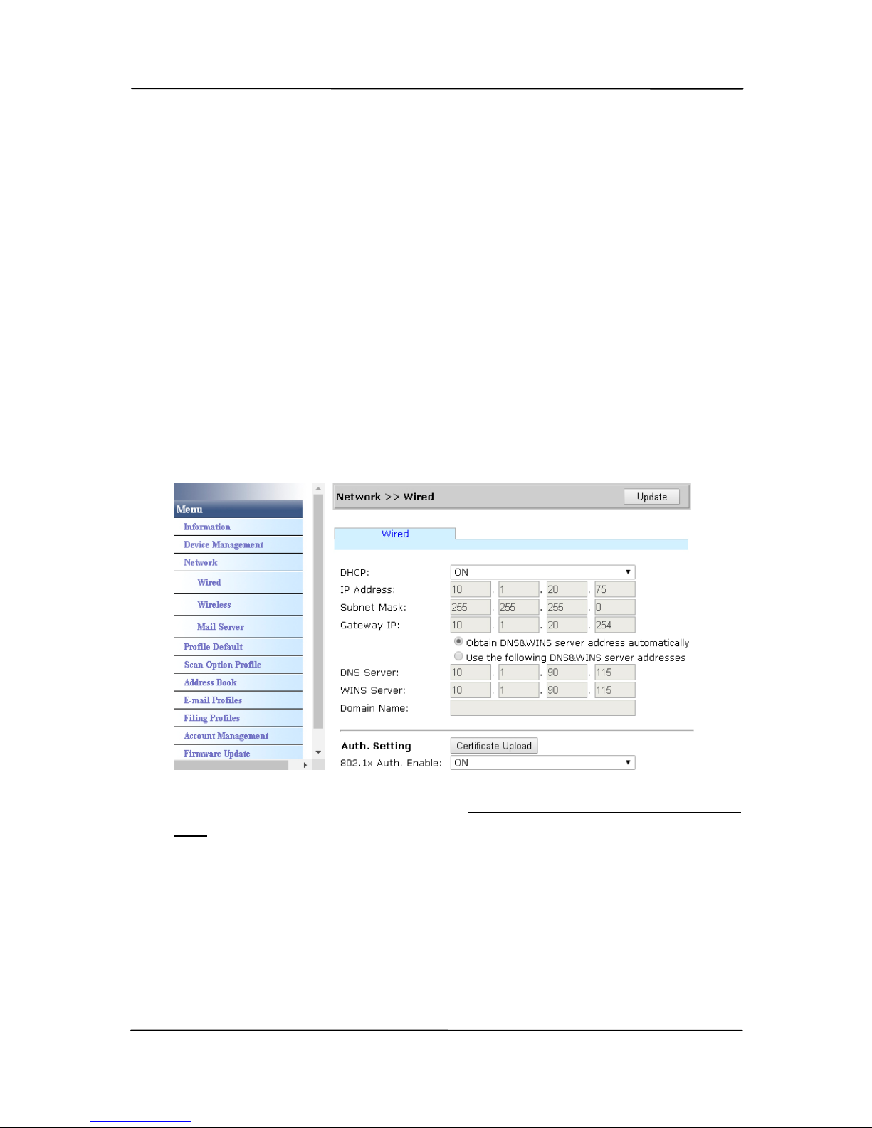
1. On the product’s web page, choose [Network] and then
[Wired] option to prompt the [Wired Network] page.
2. Refer to the preceding section 1.7 Pre-installation check
list to specify the IP address for the product.
3. After the IP address has been specified, choose [Update]
to complete and save the settings.
Page 62

User’s Manual
6-6
Upload Certificate:
If IEEE 802.1x authentication method has been used to access
a network server, the product offers the administrator to
upload the certificate information throug h the embedded web
page. To upload the certificate files, follow these steps:
1. Download the latest certificate files from y our network
administrator.
1. Open your browser and type the product’s IP address on
the URL field to prompt the product’s embedded web page.
To access complete information of the web page, please
login with the default user name and password – [admin].
The password can be changed later in the web page.
2. On the product’s web page, choose [Network]>[Wired]
to prompt the [Wired Settings] page.
3. Choose [Certificate Upload].
4. Click [Browse] on the item of [Root Certificate], [Client
Certificate], [Client Key], and [Client Password]
respectively to choose the certificate file on your
computer.
5. Click [Update] to start updating the certificate.
Page 63

User’s Manual
6-7
6.2.2 Specifying the Product’s Wireless Network
Settings
1. On the product’s web page, choose
[Network]>[wireless] option to prompt the [Wireless]
page.
2. Refer to the subsequent section – 7.2 Connecting to a
Wireless Network to specify your wireless network
settings.
6.2.3 Specifying the Product’s Mail Server Settings
1. On the product’s web page, choose [Network]>[Mail
server] option to prompt the [Mail server] page.
2. Refer to the preceding section - 2.7 Specifying the
Product’s Mail Server to specify the mail server
information.
Page 64
User’s Manual
6-8
6.3 Configuring the Profile Default for USB
To change the profile defaul
t for scan-to-USB:
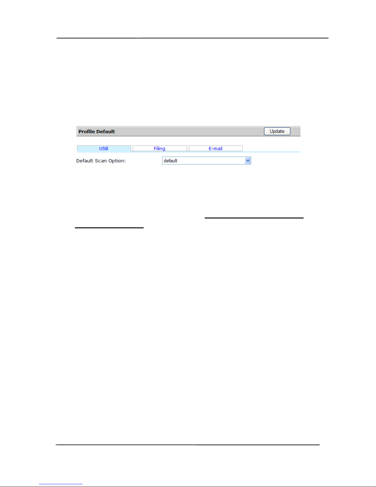
1. On the product’s web page, choose [Profile Default] to
prompt the [Profile Default ] page.
2. Make sure the [USB] tab has been selected.
3. Choose your desired default scan option from the list.
Refer to the preceding section, 5.1 Editing Your Scan
Option Profiles, to make various scan options to fit a
variety of scanning tasks.
4. Click [Update] to save the setting.
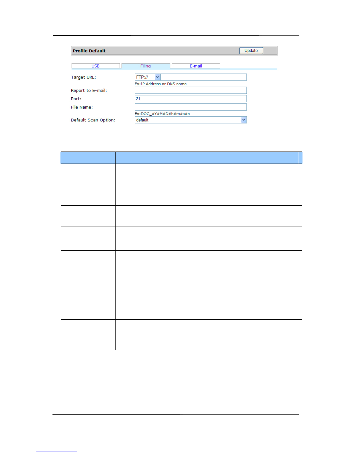
6.4 Configuring the Profile Default for Filing
T
o change the profile default for Filing:
1. Repeat Step 1 to Step 2 from the previous section,
Configuring the Profile Default for USB. The [Profile
Default] page appears.
2. Choose [Filing] to prompt the [Profile Default for
Filing] page.
Page 65
User’s Manual
6-9
2. Refer to the following table to enter your desired settings.
Item Description
Target
URL
Enter the default IP address and the shared
folder name of your filing server.
Protocol: Enter the type of protocol of your
filing server. Choice: FTP, CIFS
Report to
E-mail
Enter an e-mail address if you wish to send
the filing report to the e-mail.
Port Enter the port number of t he filing server.
* 21 (FTP), 139 (CIFS)
File Name Enter your desired prefix for the file name.
Naming Method:
Prefix_YYMMDDHHMMSS_xxx.file format.
For example,
「DOC_150213144840_001.pdf」indicates
2015 (year) 2 (February) 13 (date) 14 (hour)
48 (minute) 40 (second) 001 (serial number)
Default
Scan
Option
Choose the default scan option for the
scanned image of the filing profile.
3. Click [Update] to save the setting.
Page 66
User’s Manual
6-10
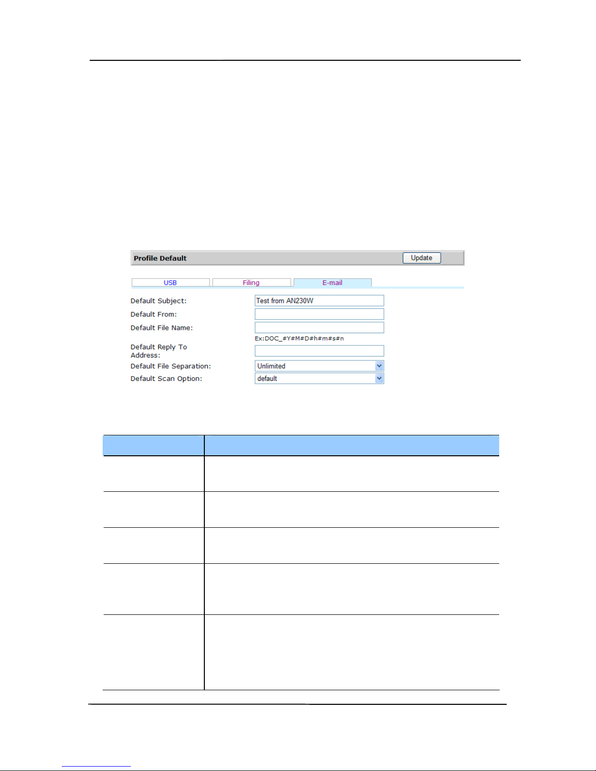
6.5 Configuring the Profile Default for E-mail
To change the default setti
ng for scan-to-E-mail:
1. Repeat Step 1 to Step 2 from the previous section,
Configuring the Profile Default for USB. The [Profile
Default] page appears.
2. Choose [E-mail] to prompt the [Profile Default for E-
mail] page.
3. Refer to the following table to enter your desired settings.
Item Description
Default
Subject
Enter the default subject for all outgoing
mails.
Default
From
Enter your default From address for all
outgoing mails.
Default File
Name
Enter your default file name.
Default
Reply To
Address
Enter your default [reply to] address for
all outgoing mails.
Default File
Separation
Enter the default file separation limit of
the attachment file for all outgoing mails.
Choice: 1MB/3M/5M/10M/30MB/
Unlimited
Page 67

User’s Manual
6-11
Default
Scan
Option
Choose the default scan option for all
outgoing mails.
4. Click [Update] to save the setting.
Page 68

User’s Manual
6-12
6.6 Managing Web Site’s Accounts
If the system administrator wish to add more users to access
and manage the product’s web page, it is possible to add more
users to login the web page through account management.
To add a new account,
1. On the product’s web page, choose [Account
Management] and then [New] to add a new account.
2. Enter user name and password for the new account.
3. C
lick [Submit] to save the settings.
4. A new account will be shown in th e list.
To Edit a current account,
1. On the product’s web page, choose [Account
Management].
2. Choose the account which you want to Edit.
3. A [Edit] page will be displayed. Edit your user name or
password.
4. Click [Submit] to save the settings.
To delete a current account,
1. On the product’s web page, choose [Account
Management].
2. Choose the account which you want to delete.
3. A Confirmation dialog box will be prompted. Choose [Yes]
to delete or [Cancel] to quit.
Page 69

User’s Manual
6-13
6.7 Updating the Firmware
To update the product’s fi
rmware, follow these steps:
1. Download the latest firmware file from our web page at
www.avision.com to your computer.
2. Open your browser and type the product’s IP address on
the URL field to prompt the product’s embedded web page.
To access complete information of the web page, please
l
ogin with the default user name and password – [admin].
The password can be changed later in the web page.
3. On the product’s web page, choose [Firmware Update]
to prompt the [Firmware Update] page.
4. Click [Browse] to choose the firmware file on your
computer.
5. Click [Update] to start updating the firmware.
6. Turn off and then turn on the scanner to complete the
firmware update.
Page 70

User’s Manual
6-14
6.8 Exporting and Importing System Data
To easily manage several AN230W in the network, the machine
provi
des a useful feature to allow system administrator to
export the system data of one AN230W into a file and then
import this data to other AN230W in the network.
For example, the address book, filing profile, and defau lt
systems settings of one AN230W can be first exported to a file
as a backup and then import these files to other AN230W.
Follow the procedure described in below to export and then
import your system data.
6.8.1 Exporting System Data
To export system data,
1. On the product’s web page, choose [Import/Export].
2. C
hoose the system data you want to export. Choice:
Address Book, Filing Profile, Settings (Device Management,
Account Management, Mail Server/LDAP Server, E-Mail
Default, Filing Default).
3. Choose [Export Now]. The selected system data will be
exported into a file. If [address book] is selected, an
AN230W_addressbook.csv file will be generated. If [filing
profile] or [settings] is selected, an AN230W_profile.json
or AN230W_setting will be generated...
4. Save the exported file into your computer as a backup.
Page 71

User’s Manual
6-15
6.8.2 Importing System Data
To import system data,
1. On the product’s web page, choose [Import/Export].
2. C
hoose the system data you want to import. Choice:
Address Book, Filing Profile, Settings (Device Management,
Account Management, Mail Server/LDAP Server, E-Mail
Default, Filing Default).
3. On the Importing option, choose [Browse] to locate the
system data which you have been previously exported.
4. Choose [Import Now] to start importing the system data
to your machine. The current system data will be
overwritten.
Page 72
User’s Manual
7-1
7. Starting a Scan from Your
Mobile Device
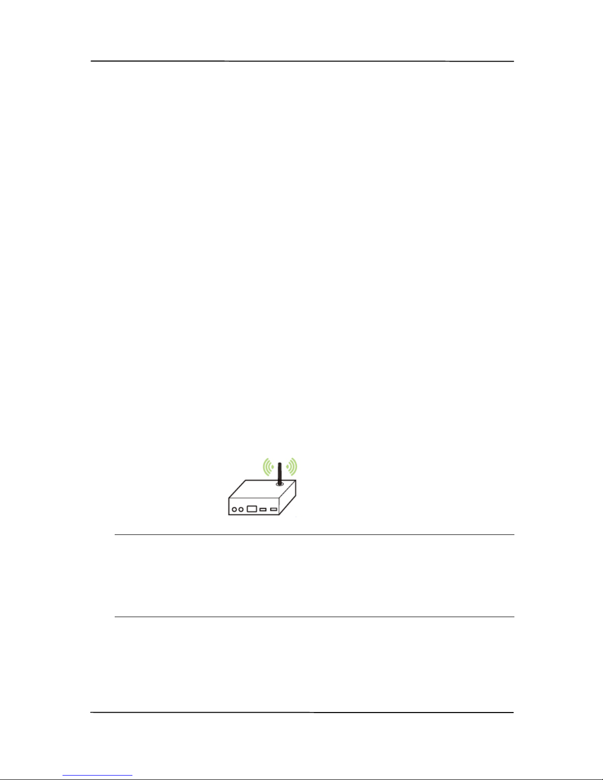
With a built-in Wi-Fi module, the scanner can be converted into
a wireless device. When a mobile device is use, the scanned
images can be received from the mobile device.
7.1 Making Preparation
To connect the scanner to a wireless LAN, prepare the
f
ollowings:
An environment in which a wireless LAN is available
When connecting the scanner to a wireless LAN, you may
need information for a wireless access point such as an
SSID (network name) and a security key (password). For
details, contact your Network Administrator or refer to the
manual for the wireless access point.
Attention!
Do not place obstacles that block radio waves (e.g. walls or
metal plates) or devices that cause radio wave interference
(e.g. cordless phones) within 100 mm of the scanner, or
near your wireless access point.
Page 73
User’s Manual
7-2
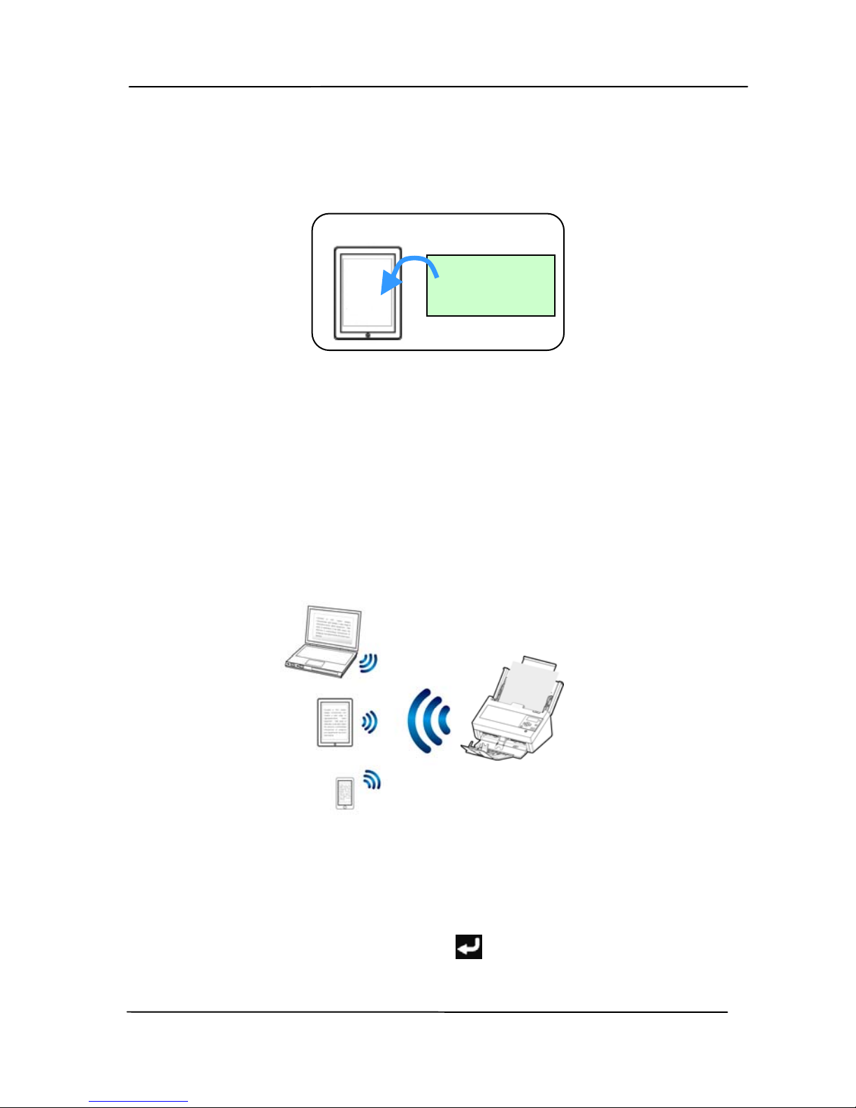
MB Application
Download the MB Application on your mobile device from
an application store such as Google Play.
7.2 Connecting to a wireless network
7.2.1 Connect to a Wi-Fi network in an AP (Access
Point) mode
In AP (Access Point) mode, your mobile devices and the
scanner are connected wirelessly wi
thout an additional AP
(Access Point) since the scanner itself works as an AP.
1. Turn on the Wi-Fi switch on the back of the scanner. The
Wi-Fi LED light will be flashing an d then turn solidly on.
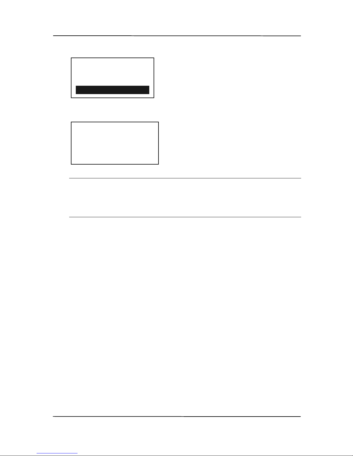
2. On the control panel of your scanner, use ▼ to scroll down
to [AP Mode] and then press
to select it.
MB
Application
- AP (Access Point)
Page 74
User’s Manual
7-3
3. The SSID and IP Address will be displayed.
Note:
The IP address 192.168.200.1 is the permanent IP address
for the scanner when it connects to a wireless network in
AP mode.
4. On your mobile devices, make sure Avision–xxxxxx
(xxxxxx indicates the last six digits of the Mac Address)
has been selected as your network name (SSID).
Filing Profiles
Scan to USB
Scan to PC
AP Mode
SSID:
Avision-DFAF37
IP Address:
192.168.2.101
Page 75
User’s Manual
7-4
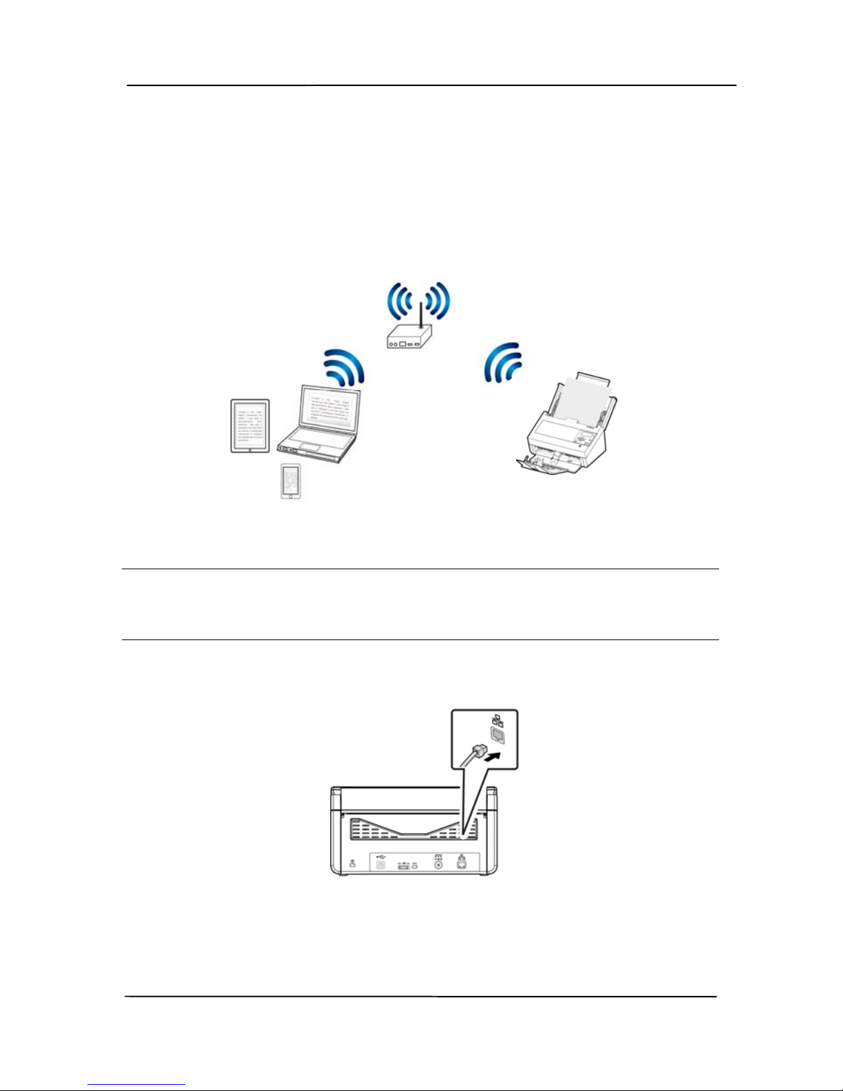
7.2.2 Connect the scanner to a Wi-Fi network in a client
mode (default mode)
In a Cl
ient mode, your mobile devices and scanner are
connected wirelessly through an additional AP (Access Point).
This mode is also the default wireless mode.
Connect Your Scanner to an AP (Access Point):
Important:
Note to connect the scanner in a wireless network, please first
disconnect the Ethernet cable connecting to your scanner.
a. Connect the scanner to a wired network via a network
cable.
b. Make sure the Wi-Fi LED light is flashing. If not, turn on
the Wi-Fi switch on the back of the scanner. The Wi-Fi
LED light will be flashing.
- AP (Access Point)
Page 76
User’s Manual
7-5
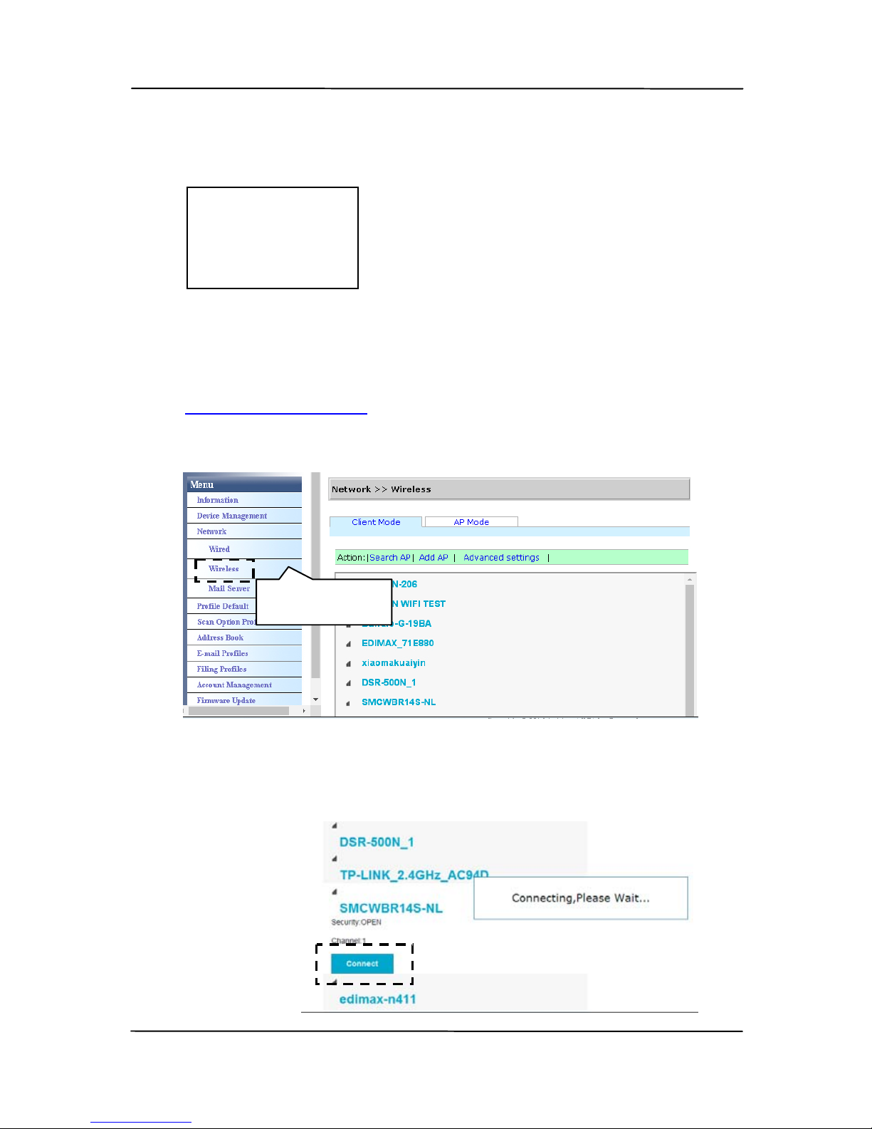
c. Press the [i] button on the control panel and then choose
[Network]. The IP for the wired network will be
displayed.
d. Open your browser (i.e. 10 or above).
e. Type ETHERNET IP address on the URL bar (for example,
http://10.1.20.119
) to prompt the embedded web page.
Choose [Network Settings]>[Wireless] to prompt the
wireless page.
f. Select an AP(Access Point) and click [Connect] Connect
the scanner to a specified Access Point, for example,
SMCWBR14S-NL.
<Wired>
IP Address:
10.1.20.119
Mac Address:
Wireless
Page 77
User’s Manual
7-6
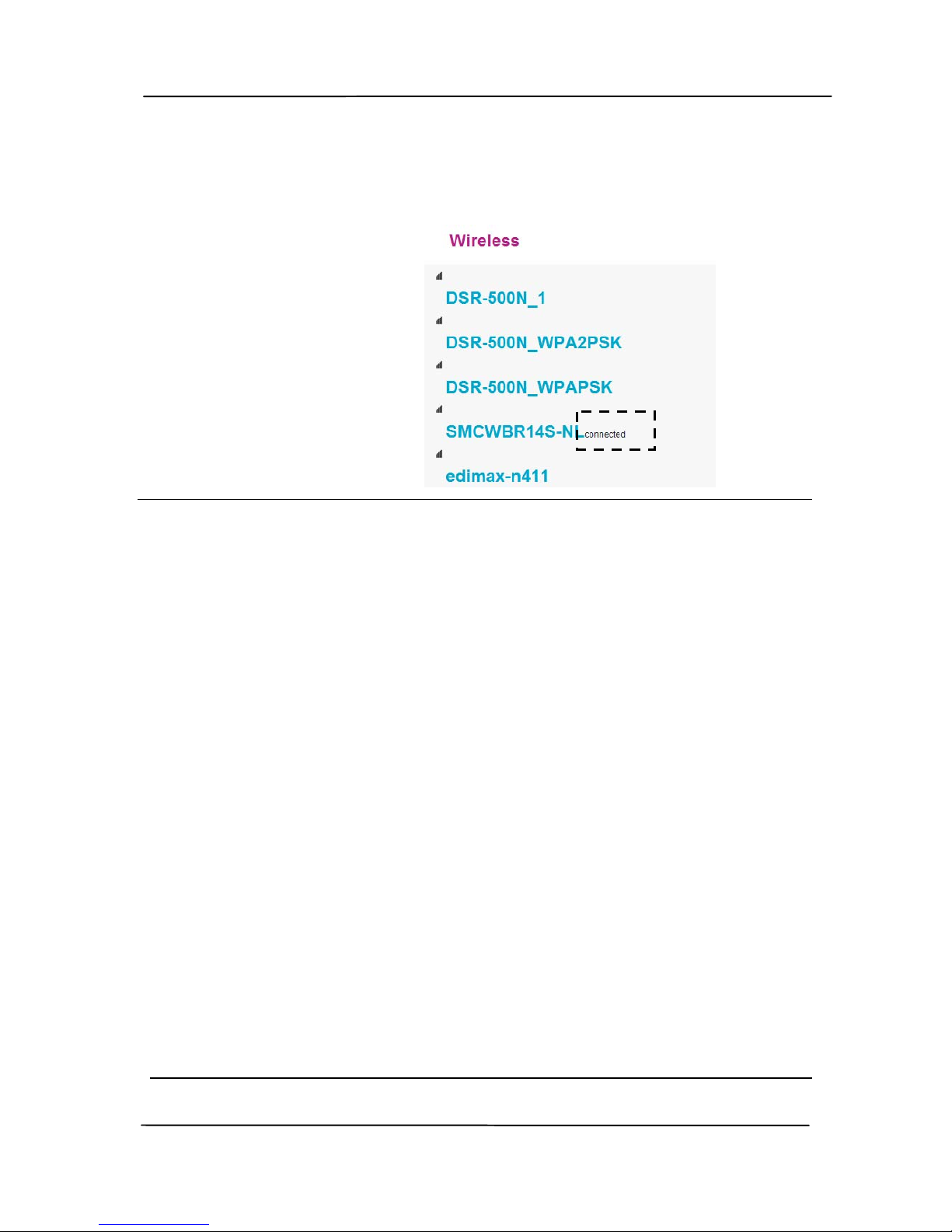
g. In a few seconds, if the connection is successful, the
connected Access Point will be marked with [connected]
as shown.
Note:
1. The product does not allow the wired and wireless mode to
work at the same time. Therefore, once the scanner has
successfully connected to a wireless access point, the
webpage which you have just connected via the Ethernet
cable can no longer work.
2. If you want to make the web page available to Edit the
settings or connect the scanner to another wireless access
point, please follow these steps to prompt the scanner’s
web page:
1). On your wireless computer or device, select the same
AP (access point) as the scanner. For example,
SMCWBR14S-NL.
2). Open the browser of your wireless device.
3). Type the wireless IP address for the scanner (press the
[i] button on the control panel to find the wireless IP
address) on the URL field. The scanner’s web page will
be prompted.
4). Edit the settings or follow step e ~ g to connect the
scanner to another AP (access point).
Page 78
User’s Manual
7-7
Note:
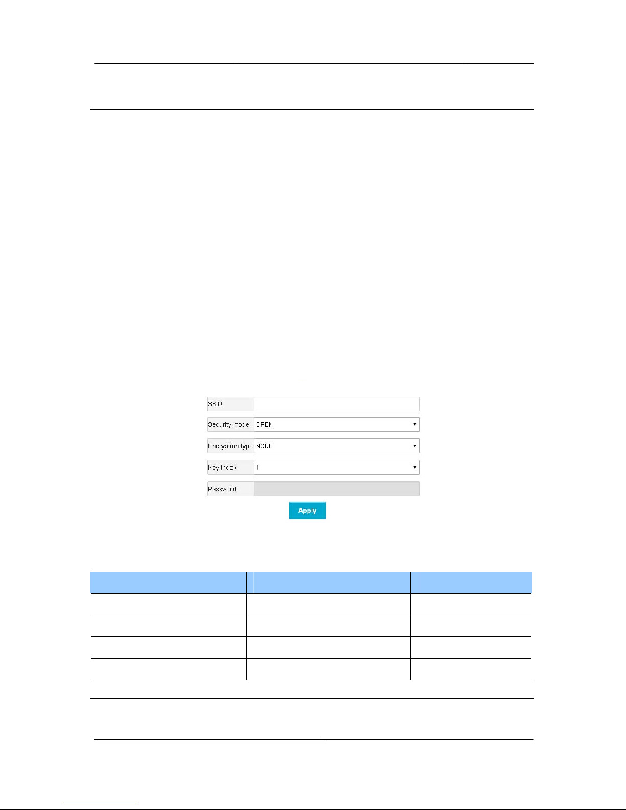
If your access point is set to not broadcast the SSID, y ou will
have to manually add the SSID name on the product’s web
page.
1. Connect the Ethernet cable to the LAN port on the back of
the scanner.
2. Open your browser and type the wireless IP address on
the URL field.
3. Choose [Network]>[Wireless]> [Add AP] on the
product’s embedded web page and enter the SSID
name/security mode/encryption type/network key and
then click [Apply] to search the wireless network
manually.
Your scanner supports the following authentication methods:
Security mode Encryption method
Key Index
WEPAUTO WEP 1, 2, 3, 4
WPAPSK TKIP, AES, TKIPAES X
WPA2PSK TKIP, AES, TKIPAES X
WPA1PSKWPA2PSK TKIPAES X
Add AP
Page 79
User’s Manual
7-8
7.2.3 Connect to a wireless access point using the WPS
button
You may connect the scanner to a WP
S compatible wireless
access point by pressing the WPS button on the back of the
scanner.
Before You Begin!
To enable the WPS connection of your access point, please
refer to the user’s guide of your access point.
Perform the following procedure to connect.
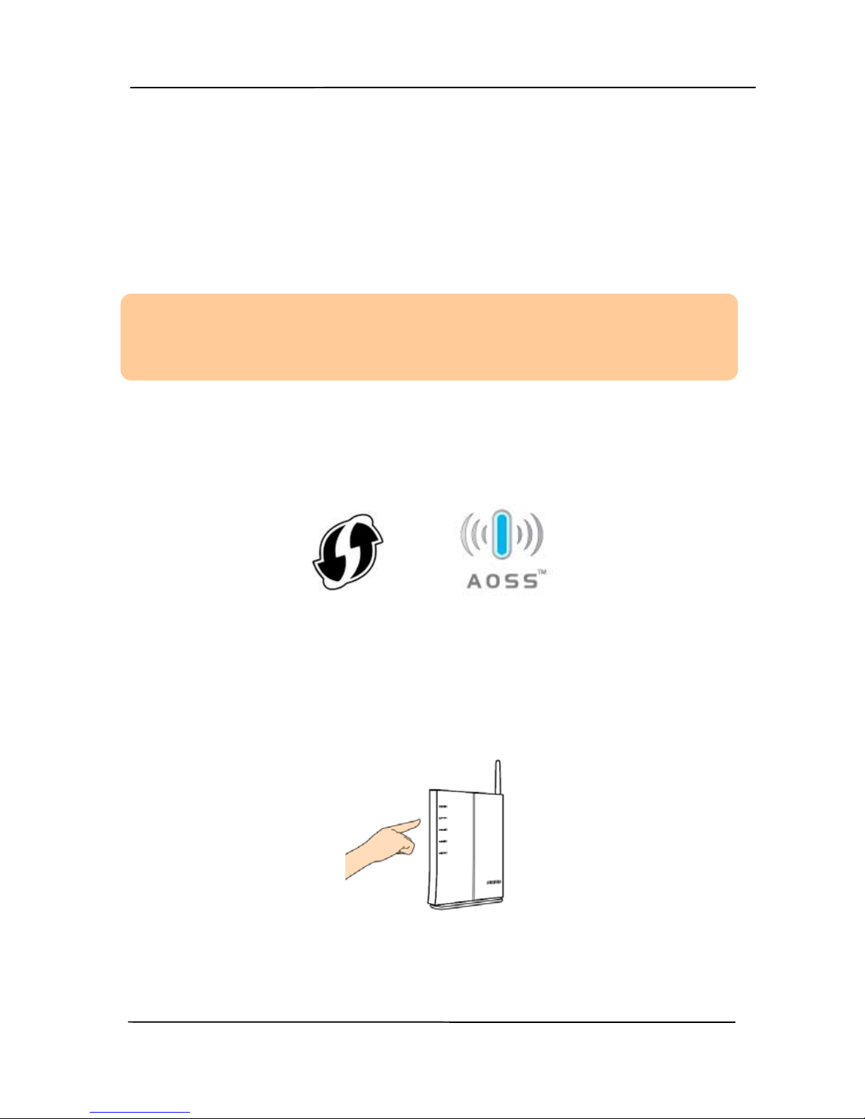
1. Confirm your wireless access point/router has the WPS or
AOSS
TM
symbol as shown below.
2. Turn on the Wi-Fi switch on the back of the scanner. The
Wi-Fi LED light will be flashing .
3. Press the WPS button of your wireless access point. (You
may refer to the user’s guide of your access point/router for
instructions on how to use the WPS button.)
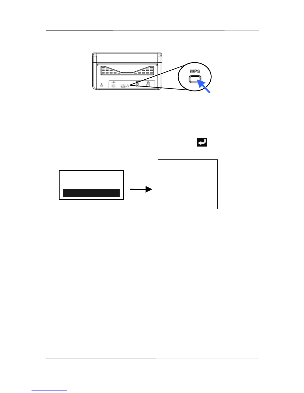
4. Press and hold the WPS button on the back of the scanner
for about 5 seconds within 2 minutes after pressing the
WPS button of your wireless access point.
Page 80
User’s Manual
7-9
5. If the connection is successful, the Wi-Fi LED light of the
scanner will turn solidly on.
6. Check the AP name and IP address of the scanner by
pressing the [i] button on the scanner and then use ▼ to
scroll down to [Network] and then press
to select it.
If the AP name is your selected AP, it means the wireless
connection via the WPS button is successful.
<Wireless>
AP:
XXXXXXXX
IP Address:
10.1.23.156
Information
Scanner
Network
Page 81
User’s Manual
7-10
7.3 Scanning a document from a mobile device
Make sure that the MB Application (Scan App) has been
in
stalled on your mobile device. The MB Application can be
purchased for free from an application store such as Google
Play.
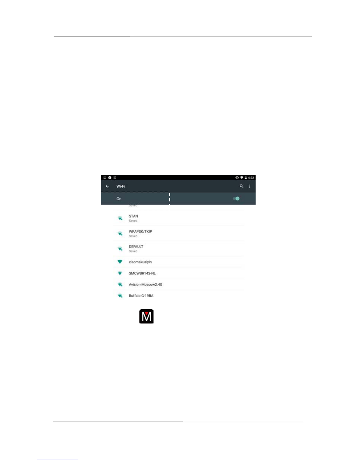
1. Enable [Wi-Fi] from [Settings] of your wireless computer,
smartphone, or tablet and then choose the same network
name (SSID) of your scanner. For example, SMCWBR14SNL.
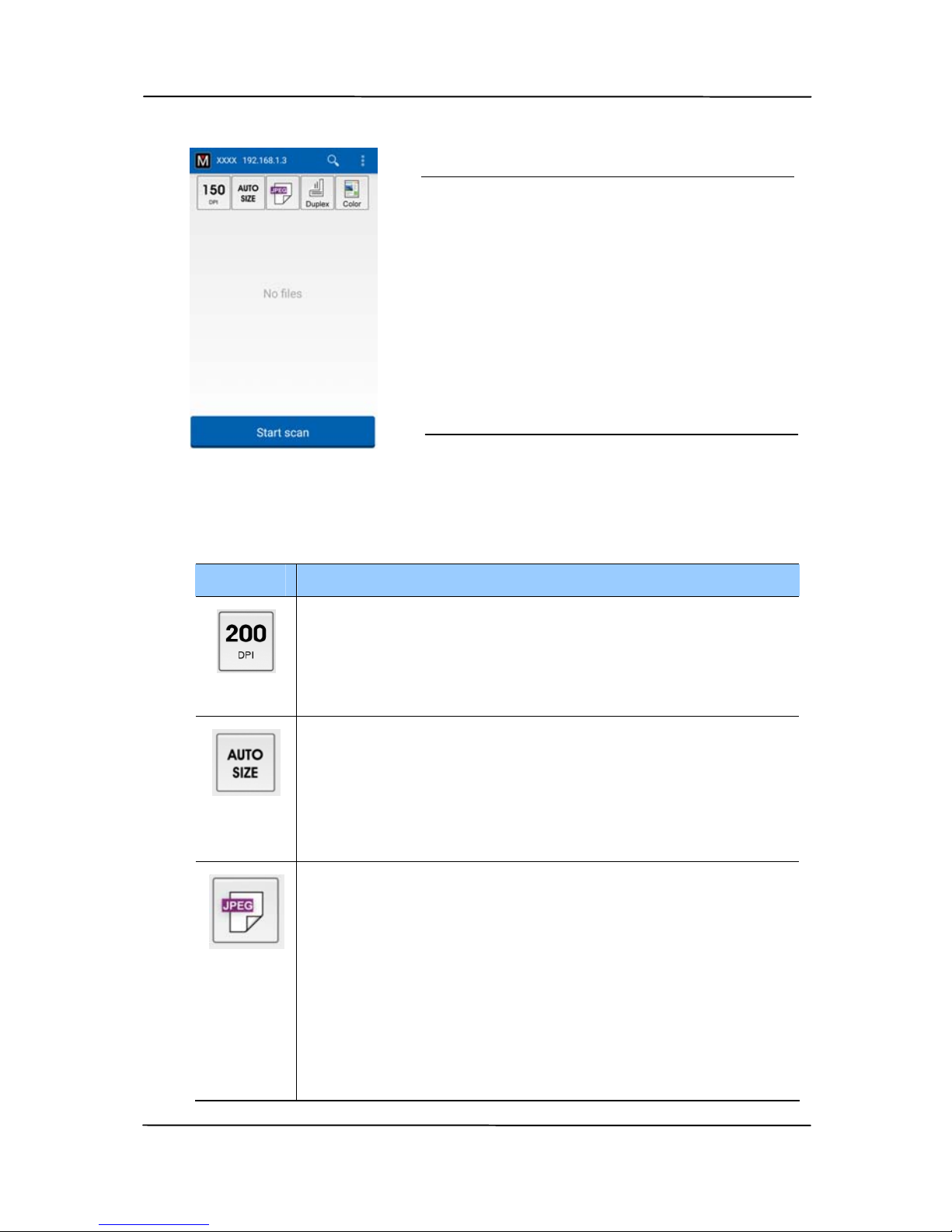
2. Tap the MB app (
) on the screen to launch the Scan
Application. The main window will be displayed and the
application will automatically search a scanner in the same
wireless LAN. If successful, [Start scan] will be displayed
at the bottom as shown below.
Page 82
User’s Manual
7-11
3. Check if the default settings meet your requirements. If
not, change the scan settings to fit your specific scanning
task.
Item Description
Resolution: Select your desired resolution.
The higher resolution, the greater the image
quality and disk space.
Choice: *150, 200, 300 dpi
Scan Size: Select your paper size or you may
choose Auto to let the scanner detect your
document size automatically.
Choice: *Auto size, A4, LTR (Letter), LGL
(Legal), 4x6, 5x7
File Format: Select the file format for your
image.
Choice: *JPEG, PDF, TIFF
Note:
The JPEG file does not support the B&W
image.
The TIFF file format supports only the
B&W image.
ATTENTION:
If the scanner is not found, please
check the followings:
1. The scanner is not ready yet.
Tap [More Settings] and then
[Search scanner] to search
the scanner again.
2. Check if the mobile device and
the scanner are in the same
wireless LAN.
Page 83
User’s Manual
7-12
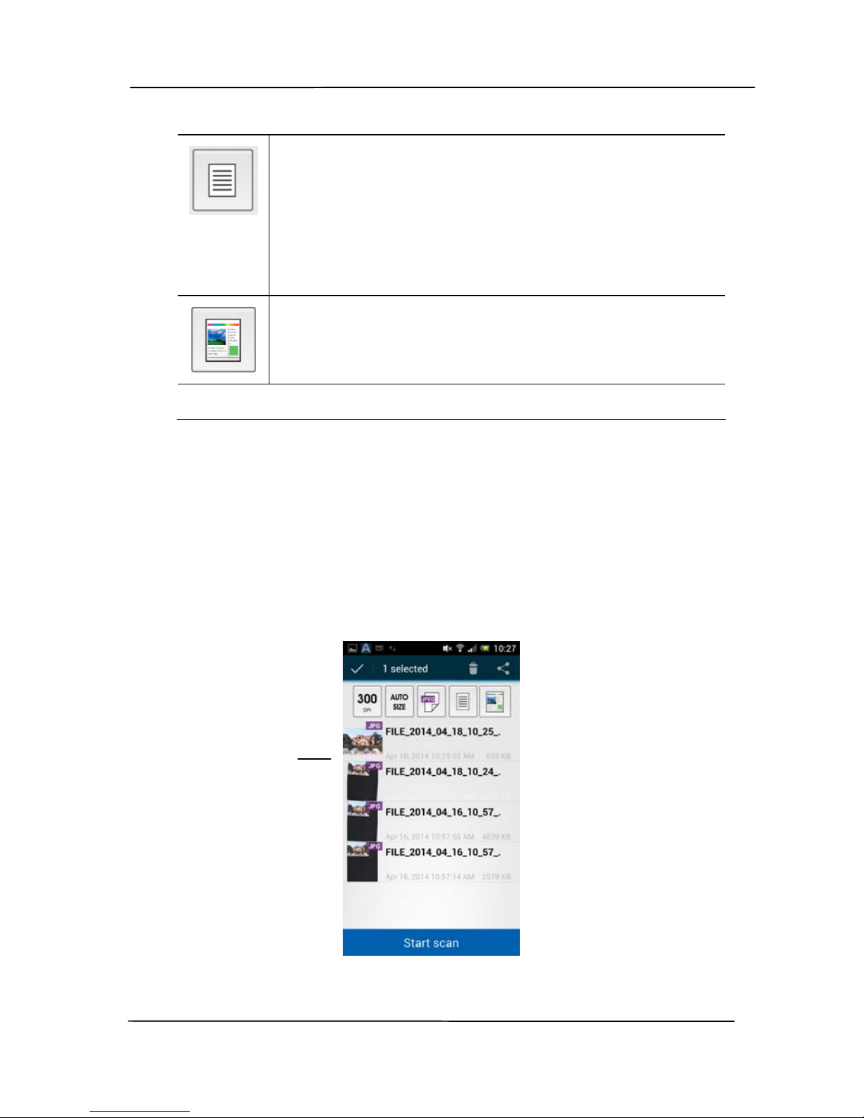
Select to scan the front side (simplex) or
both the front side and the rear side (duplex)
of your document.
Choice: *Simplex, Duplex
Note: The duplex mode is available to scan
from the auto document feeder only.
Color Mode: Select your desired image mode.
Choice: *Color, B&W, Gray
* Default settings
4. Load a page to the auto document or place a page on the
flat bed.
5. Tap the [Start scan] button. (Choose your scanner if
there is more than one scanner connected to the network).
In a second, the scanner begins scanning the document
and the thumbnail scanned image will be displayed.
6. Tap the thumbnail image to view the entire image.
The
Thumbnail
Image
Page 84
User’s Manual
7-13
7.4 Scanning From A NFC-Enabled Mobile Device
The scanner supports NFC (Near Fi
eld Communication), a
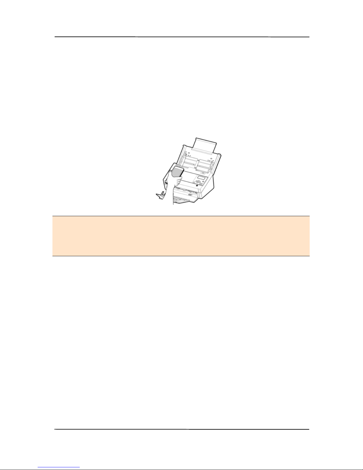
short-range wireless communication technology. By placing an
NFC-enabled mobile device over the NFC mark on the
operation panel of the scanner, you can start a scan and
receive images directly from your mobile device.
Before Using the NFC Function:
1. Download and install "MB" App. The Scan App can be
purchased for free from Google Play.
2. Make sure Wi-Fi is enabled for the scanner.
Scanning with the NFC Function
1. Load a document facing down to the feeder of the
scanner.
2. Hold your mobile device against the NFC logo on th e
operational panel of the scanner.
3. If the NFC connection is successful, the MB app on your
mobile device will be started.
Page 85

User’s Manual
7-14
4. Modify the scan settings to suit your need.
5. Tap “Start scan” to start a scan.
Note:
The NFC function has to work while the Wi-Fi is enabled for
both the scanner and your mobile device or the following
conditions will occur:
If Wi-Fi has been enabled yet no Access Point has been
connected or if Wi-Fi has not been enable on your
scanner, the MB app will be launched and displayed “No
Wi-Fi information”. Tap “OK” and close the MB app.
Solution:
On your scanner, enable Wi-Fi and then select an Access
Point.
Page 86
User’s Manual
7-15
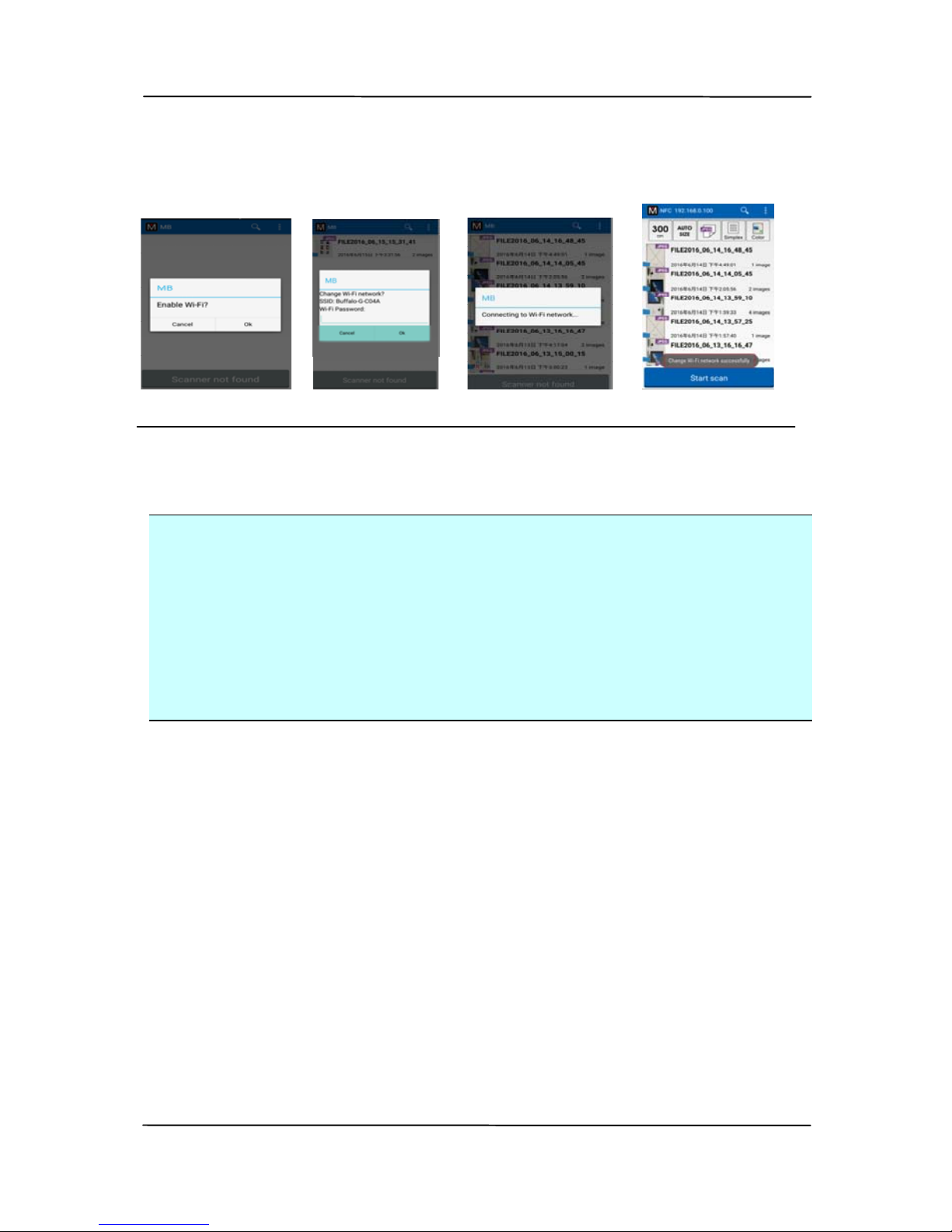
If Wi-Fi has not been enabled on your mobile device, the
MB app will guide you to enable Wi-Fi and then connect
to the Access Point as illustrated in below:
1. Enable Wi-Fi 2. Select SSID 3. Connecting Wi-Fi 4. Ready to scan
Important:
Your mobile device must support NFC.
Make sure you turn on the NFC function on your mobile
device and your scanner.
If your mobile device is not recognized, reposition your
mobile device over the NFC logo and try again.
The screen and message displayed may vary depending
on your mobile device.
Page 87
User’s Manual
8-1
8. Using the Product as a
Regular Scanner
8.1 Installing the Scanner Driver
NOTE:
1). To ensure your computer can identify the USB scanner,
please install scanner driver first before connecting the
scanner to your computer.
2). The scanner driver contains TWAIN, and WIA driver. After
the installation of scanner driver is completed, this scanner
allows you to scan via a TWAIN, ISIS, or a WIA interface.
Start your TWAIN-compliant image editing software
application to select a TWAIN or WIA user interface or your
ISIS software to select an ISIS user interface. You may
also launch Microsoft’s Scanner and Camera Wizard to scan
via a WIA user interface.
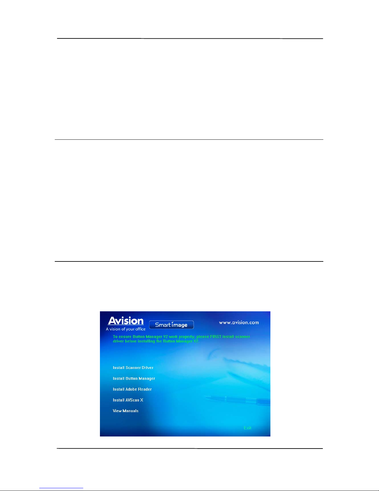
1. Place the supplied CD-ROM onto your CD-ROM drive.
2. The software installation graphic appears. If not, run
“setup.exe”.
Page 88

User’s Manual
8-2
Contents on the installation graphic:
Install Scanner Driver: To communicate with
your scanner, you need to install the scanner driver.
Install Button Manager V2: To use the buttons
on the scanner, you need to install Button Manager
V2. To ensure Button Manager V2 works properly,
please FIRST install scanner driver before installing
Button Manager V2.
Install Adobe Reader: To view the user’s
manuals for the scanner and Button Manager V2,
you need to use Adobe Reader to open and view the
manuals in pdf file format. If you already have
Adobe Reader installed on your computer, you may
disregard this item.
Install AVScan X: To scan and organize your
multi-page document(s), you can install the
software application to manage them easily and
effectively.
View Manual: Click “View Manual” to view or
print the detailed user manual for the scanner and
Button Manager V2 respectively.
3. Click Install Scanner Driver to install the scanner driver
and then click Install Button Manager V2 to install the
Button Manager V2 unto your computer.
Page 89
User’s Manual
8-3
8.2 Connecting to Computer
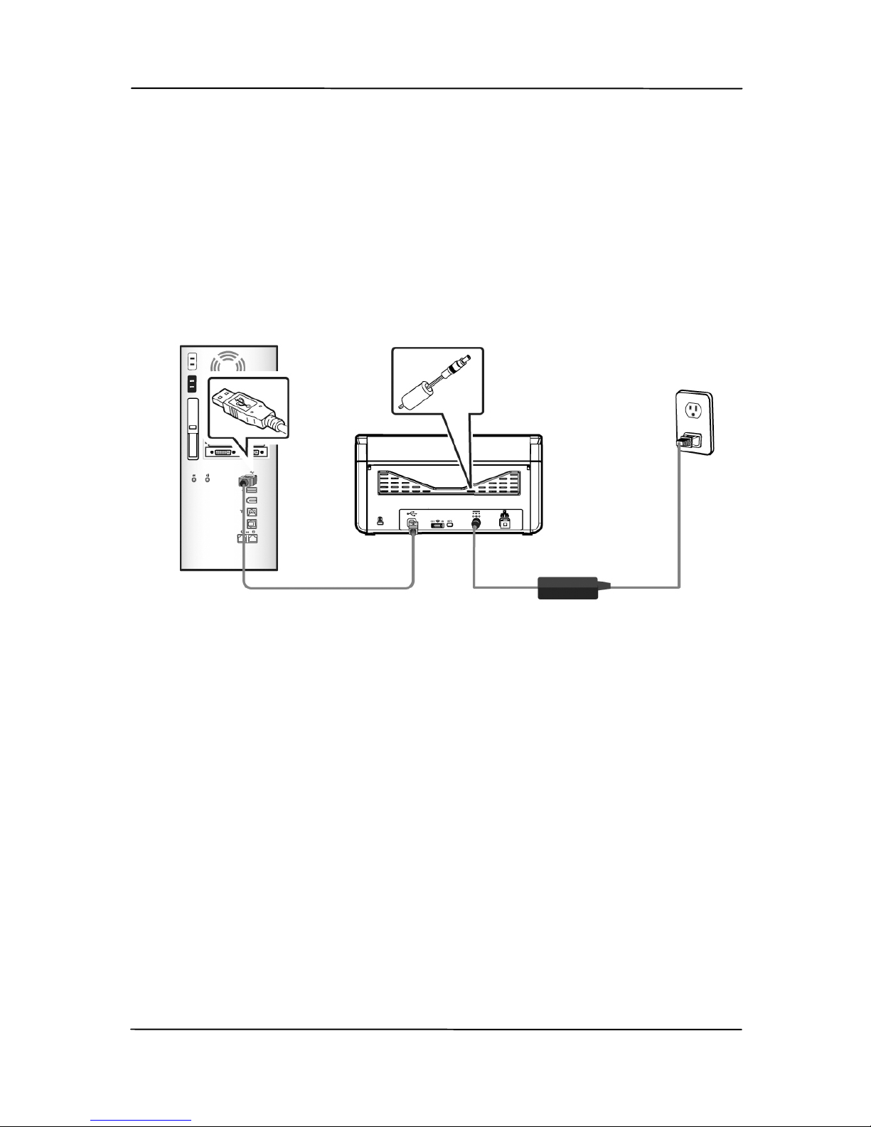
1. Connect the square end of the USB cable to the USB port of
your scanner. Connect the rectangle end to the USB port at
the rear side of your computer.
2. The computer should detect a new USB device and prompt
a “New Hardware Found” message.
3. By following the on-screen instructions, click the Next
button to continue. When the certification screen appears,
click Continue Anyway to complete the installation.
4. When the Finish dialog is prompted, click the Finish
button.
Page 90
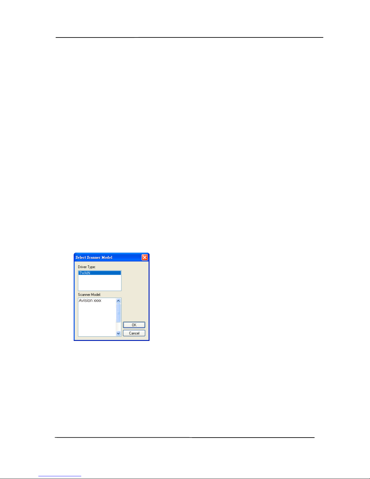
User’s Manual
8-4
8.3 Verifying Your Scanner Installation
T
o verify if your scanner installation is correct, Avision provides
you a useful test program called Avision Capture Tool. With
this tool, you can perform simple scans and view the captured
images. In addition, it helps you complete your scan at a rated
speed.
The following procedure describes how to verify your scanner
installation. If the installation is not correct, please review the
preceding section to check if the cable connection and scanner
driver have been successfully installed.
Before you begin, be sure the scanner is on.
2. Select Start>Programs>Avision xxx Scanner>Avision
Capture Tool. The Select Scanner Model dialog box w ill be
displayed.
3. Select your driver type and scanner model and click OK.
The following Avision Capture T ool dialog box will be
displayed.
Page 91
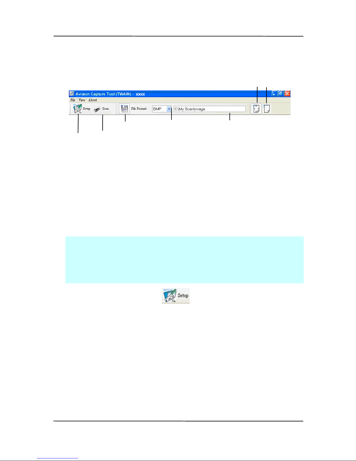
User’s Manual
8-5
4. Choose your desired file format from the File Format drop
down list box. (Default is JPEG, other choice includes TIFF,
MTIFF, PDF, MPDF, GIF, and BMP.) The supported file
formats vary depending on your scanner model.
5. Type your desired folder name and file name in the File
Path box. (Default is C:\Documents and Settings\User
Name\My Documents\My Scan\Image.)
Note: If you do not wish to save the scanned image,
deselect the Save button since default is Save Enable. In
this case, the thumbnail view will be disabled. And
therefore, after viewing all the scanned images, only the
last one will remain on the screen.
6. Click the Setup button (
) or choose Setup from the
File menu to prompt the Scanner Properties dialog box.
Setup
Actual
Size
Fit
Page
Scan
File Format
Save
File Path
Page 92
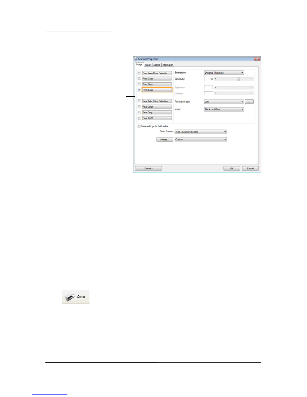
User’s Manual
8-6
7. From the Image Selection Box, choose your desired image
type for your scanned image. (Default is Front B&W) If
you have a duplex scanner, choose Front and Rear to scan
both sides of your document.
8. Click OK to quit the Scanner Properties dialog box. (To
learn more details about the Scanner Properties dialog box,
please see the subsequent chapter, Using the Scanner
Properties Dialog Box.)
9. Place your document face down on the document glass or
face up in the auto document feeder.
10. In the Scan Validation dialog box, click the Scan button
(
) or choose Scan from the File menu.
11. The document will be scanned and displayed in the Scan
Validation screen. After the scanned images have been
displayed, your scanner installation verification is
completed.
Image
Selection
Box
Page 93
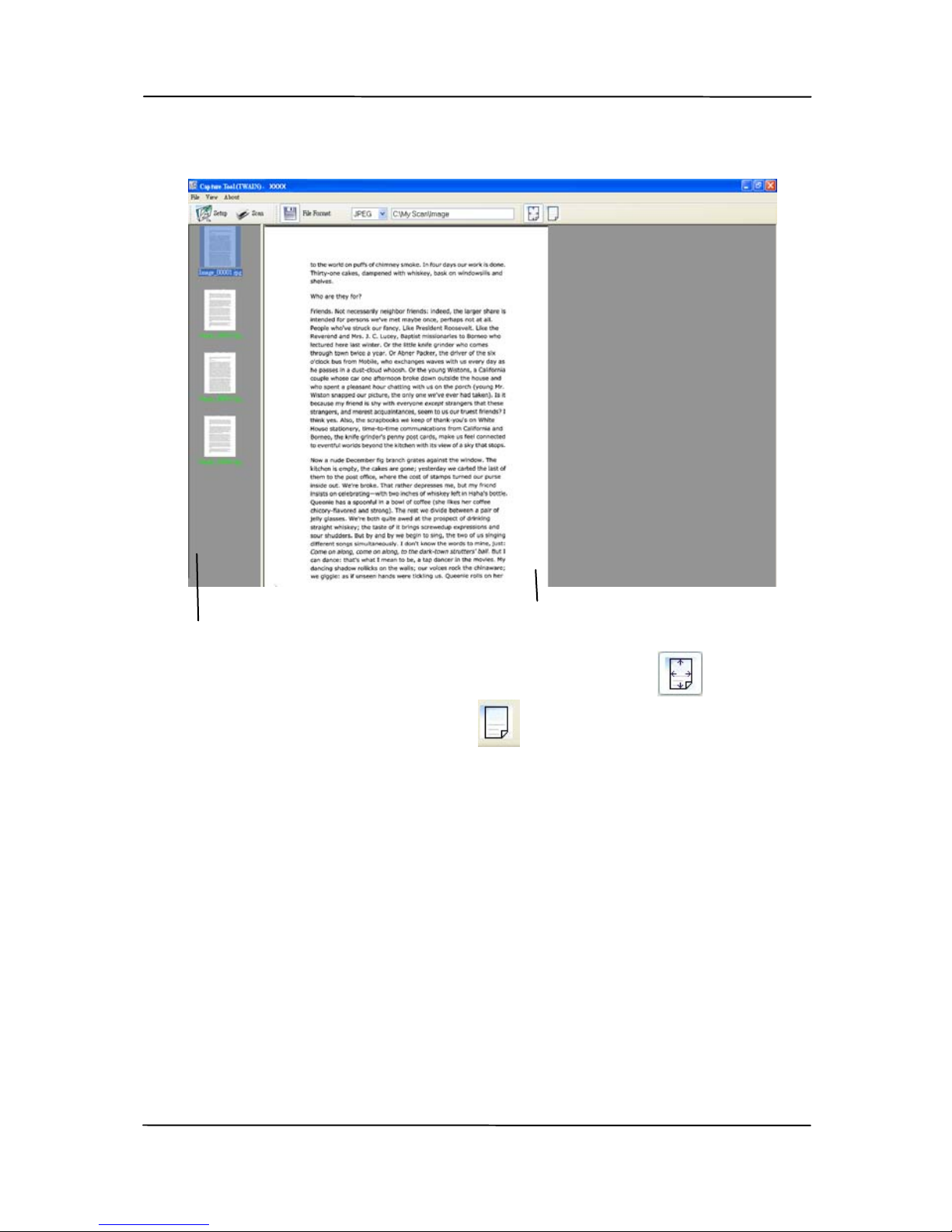
User’s Manual
8-7
12. You can view the scanned image in Fit Page (
) or
Actual Size (100%) button (
) from the Viewing toolbars
at the right side.
13. Click the Close box or Quit from the File menu to exit the
Scan Validation Tool.
Display View
Thumbnail View
Page 94
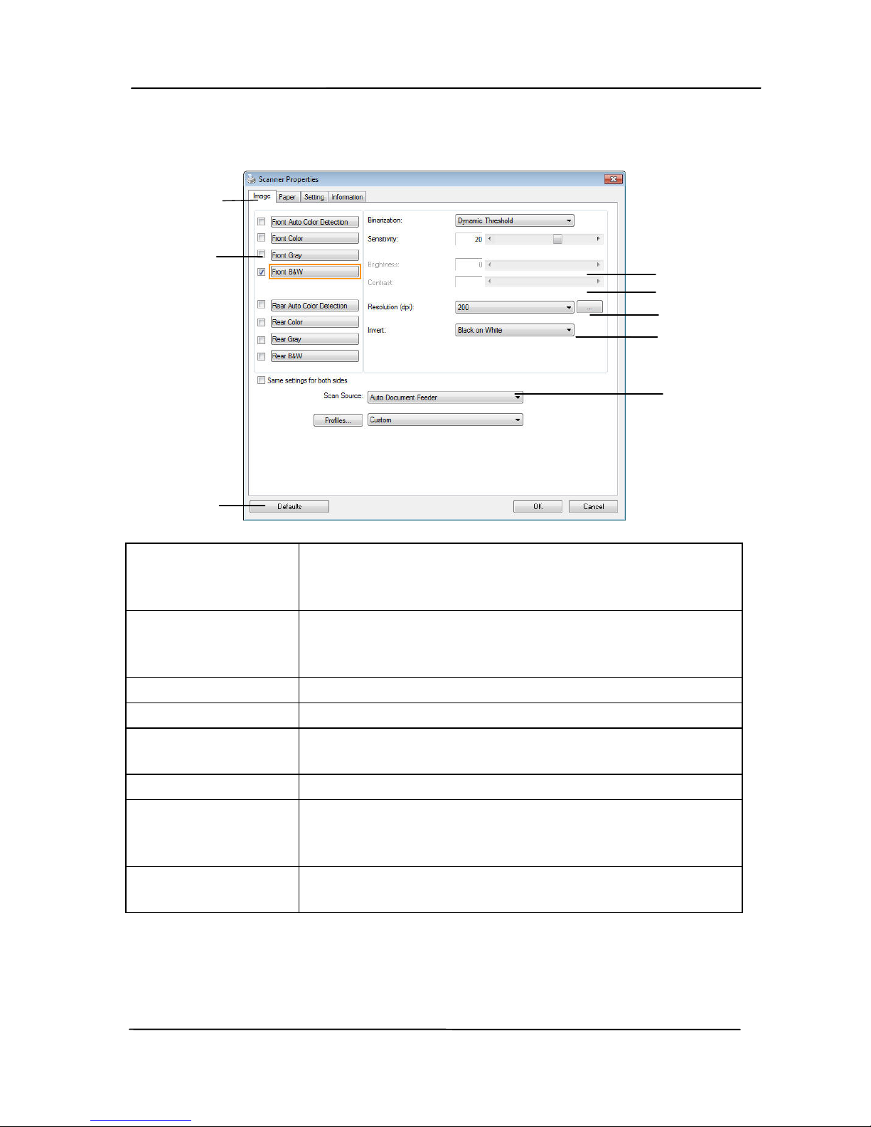
User’s Manual
8-8
8.4 A Glance of the Scanner Properties Dialog Box
1. Tab Options Choice: Image, Compression, Color Dropout,
Paper, Multi-Feed Detection, Preview, Options,
Settings, Information.
2. Image
Selection Box
Choose your image type and the side of
document you wish to scan. Options vary
based on type of scanner.
3. Brightness Adjust the brightness level from –100 to +100.
4. Contrast Adjust the contrast level from –100 to +100.
5. Resolution
Determine the quality of the scanned image.
The industry standard is 200 dpi.
6. Invert Reverse the color of your scanned image.
7. Scan Source Choice: Auto Document Feeder, Flatbed,
Flatbed (Book), Automatic (varies due to
different scanner model)
8. Defaults Reset all values on the tabs to the factory
default settings.
3
4
5
6
7
1
2
8
Page 95
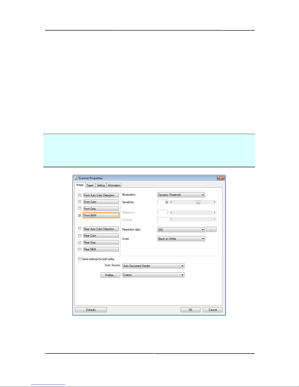
User’s Manual
9-1
9. Using the Scanner
Properties Dialog Box
The Scanner Properties dialog box allows you to configure the
scanner’s settings. It consists of several tabbed windows each
of which will be described in this chapter.
Note: In this chapter, all options are available based on a
duplex (double-side) scanner. If you have purchased a simplex
(single-side) scanner, all options are available for single sided
only.
The Scanner Properties dialog box
Page 96
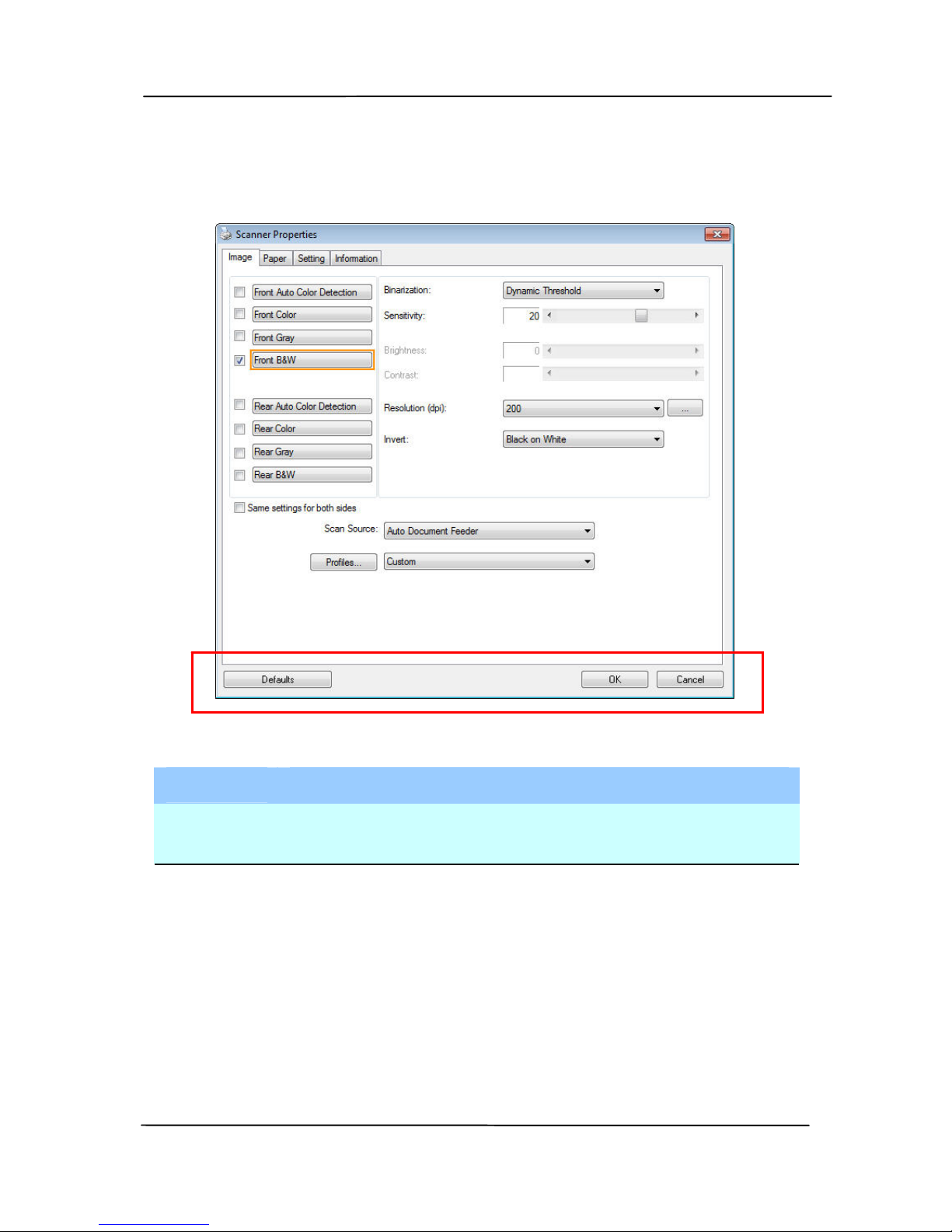
User’s Manual
9-2
9.1 Buttons on the Scanner Properties Dialog Box
The buttons on the Scanner Properties dialog box
Buttons
Description
Defaults Click the Defaults button, the factory default
settings will be shown on each tab.
Cancel Click the Cancel button to leave the Scanner
Properties dialog box.
Page 97

User’s Manual
9-3
The following table shows the default settings:
Tab name Default settings
Image Image:Front B&W
Binarization:Dynamic Threshold
Resolution:200 dpi
Invert:Blank on White
Scan Source:Auto Document Feeder
Threshold:None
Brightness:None
Contrast:None
Compression None
Color Dropout None
Paper Cropping:Automatic
Deskew:Yes
Orientation:Portrait
OverScan:0.00
Note: The availability of this option
varies due to scanner model.
Unit:Inch
Multi-Feed
Detection
None
Preview None
Options Rotation Degrees:None
Blank Page Removal:None
Edge Fill:White,0 mm
Image Control Option:None
Setting Enable Energy Saver:Enable, 15
minutes after last scan action
Show Scanning Progress:Yes
Show Warning Message:Yes
Save Settings after Closing:Yes
Imprinter Digital Imprinter
Page 98

User’s Manual
9-4
9.2 Showing or Hiding Tabs
The [Scanner Properties] dialog box is displayed in default
with three basic tabs - Image, Paper, and Information. To
show more tabs, click the [Scanner Properties] icon to access
more scan settings.
To show more tabs,
1. Click the [Scanner Properties] icon (
) on the upper
left corner, and choose [Tab] to show available tab names.
The available tabs include Compression, Color Drop out,
Preview, Rotation, Separation, Multi-Feed, Options,
Settings, and Imprinter. (Note: the options vary based on
scanner model.)
2. Choose the tab you want to display. The selected tab will
be shown with a check mark and then displayed in the
[Scanner Properties] dialog box.
3. To access the settings, click the selected tab on the top of
the [Scanner Properties] dialog box. The page of the
selected tab will be displayed.
To hide a tab window,
1. Click the [Scanner Properties] icon (
) on the upper
left corner, and choose [Tabs] to show available tab
names.
2. Choose the tab you want to hide. Then, the selected tab
will be hided in the [Scanner Properties] dialog box.
Note: The [Image], [Paper], and [Information] tab can
not be hided since they preprogrammed to be displayed by
default.
Page 99
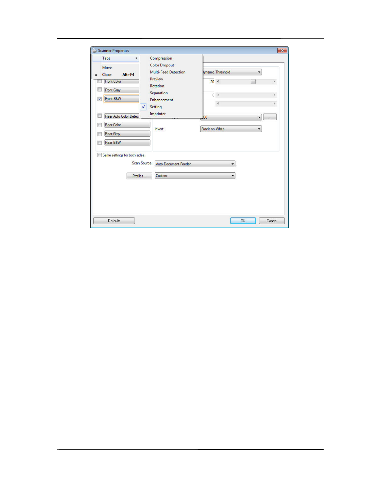
User’s Manual
9-5
Page 100
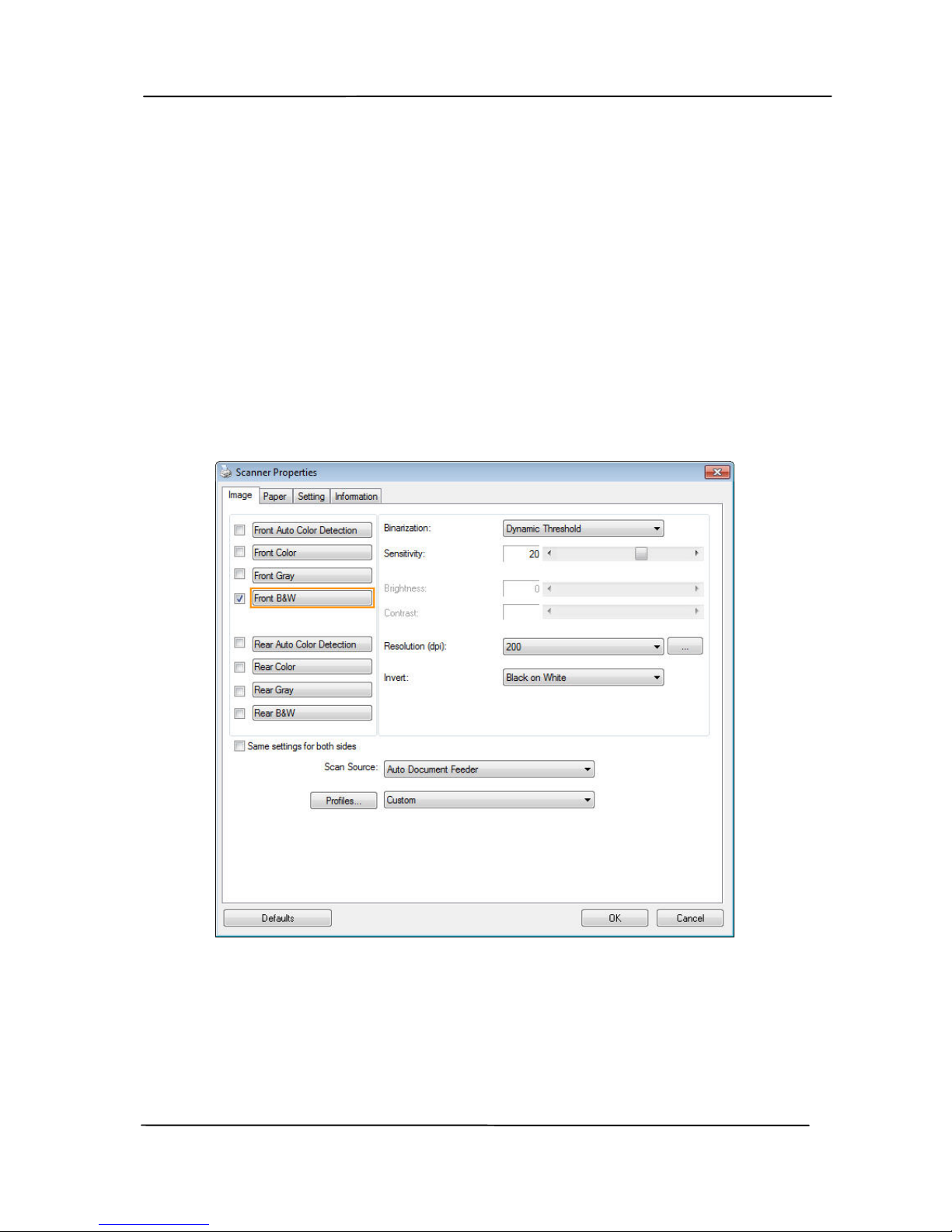
User’s Manual
9-6
9.3 The Image Tab
The Image tab allows you to choose the front side and (or) the
rear side of your document, the type of image, and to set
several basic scan settings. Note that except for the resolution,
you can set individual scan settings for the front side and the
rear side. For example, all settings in the Image tab,
Compression tab, Color Dropout tab can be set individually for
the front and the rear side. However, the settings in the Paper
tab, the Option tab, and the Setting tab have to be set the
same for the front and rear side.
The Image tab dialog box
 Loading...