

Page 1

A4 Portable Scanner
User’s Manual
Regulatory model: FF-1105B
manual-en-250-0781-E-IS25-v1
Avision Inc.
Page 2

User’s Manual
ii
Trademarks
Microsoft is a U.S. registered trademark of Microsoft
Corporation.
Windows, Windows Vista, Windows 7 and Windows 8 are either
registered trademarks or trademarks of Microsoft Corporation in
the United States and/or other countries.
IBM, IBM PC are registered trademarks of International Business
Machines Corp.
Other brands and product names herein are trademarks or
registered trademarks of their res pect ive holders.
Copyright
All rights reserved. No part of this publication may be
reproduced, transmitted, transcribed, stored in a retrieval
system, or translated into any language or computer language,
in any form or by any means, electronic, mechanical, magnetic,
optical, chemical, manual, or otherwise, without the prior
written permission.
Material scanned by this product may be protected by
governmental laws and other regulations such as copyright
laws. Th e customer is solely responsible for complying with all
such laws and regulations.
Warranty
The information contained in this document is subject to
change without notice.
The manufacturer makes no warranty of any kind with
regard to this material, including, but not limited to, the
implied warranties of fitness for a particular purpose.
The manufacturer shall not be liable for errors contained
herein or for incidental or consequential damages in
connection with the furnishing, performance, or use of this
material.
Page 3

User’s Manual
iii
FCC Radio Frequency Interference Statement
This product has been tested and found to comply with
the limits for a class B digital device, pursuant to Part 15
of the FCC rules. Operation is subject to the following two
conditions: (1) this device may not cause harmful
interference, and (2) this device must accept any
interference received, including interference that may
cause undesired operation. The FCC Class B limits are
designed to provide reasonable protection against harmful
interference in a residential installation. This equipment
generates, uses, and can radiate radio frequency energy
and, if not installed and used in accordance with the
instructions, may cause harmful interference to radio
communications. However, there is no guarantee that
interference will not occur in a particular installation. If
this equipment does cause harmful interference to radio
or television reception, which can be determined by
turning the equipment off and on, the user is encouraged
to try to correct the interference by one or more of the
following measures:
Reorient or relocate the receiving antenna.
Increase the separation bet ween t he equipment and
receiver.
Connect the equipment into an outlet on a circuit
different from that to which the receiver is connected.
Consult your point of purchase or service
representative for additional suggestions.
Page 4

User’s Manual
iv
European Union Regulat ory Noti ce
Products bearing the CE marking comply with the following EU
Directives:
• Low Voltage Directive 2006/95/EC
• EMC Directive 2004/108/EC
CE compliance of this product is valid if powered with the
correct CE-marked AC adapter provi de d by A v ision.
This product satisfies the Class B limits of EN55022, EN55024
and safety requirements of EN 60950.
*This machine is certified as Class 1 LED product. Th is means
that this machine does not produce hazardous laser radiation.
Page 5

User’s Manual
v
Warning and cautions in using the lithium ion battery
Warning:
Danger warning to prevent the possibility of the battery
from leaking, heating, explosion, please observe the
following precautions:
• Don’t immerse the battery in water and seawater.
Please put it in cool and dry environment if no using.
• Do not discard or leave the battery near a heat source
as fire or heater
• Being charged, using the battery charger specifically for
that purpose
• Don’t reverse the positive and negative terminals
• Don’t connect the battery to an electrical outlet directly.
• Don’t connect the positive and negative terminal
directly with metal objects such as wire. Short
terminals of battery is strictly prohibited, it may
damage batter y.
• Do not transport and store the battery together with
metal objects such as necklaces, hairpins.
• Do not strike, throw or trample the battery.
• Do not directly solder the battery and pierce the battery
with a nail or other sharp object
• Do not use lithium ion battery and others different
lithium polymer battery model in mixture
• Prohibition of use of damaged cells
• Don’t bend or fold se aling edge. Don’t open or deform
folding edge Don’t fillet the end of the folding edge
• Don’t fall, hit, bend battery body.
• Battery pack designing and packing Prohibition injury
batteries.
• Never disassemble the cells.
• The battery replacement s h al l be done only by either
cells s upplier or dev ice suppl ier and nev e r be don e by
the user.
• Keep the battery away from babies.
• Any components contacting these two edges, they must
be insulated.
Page 6

User’s Manual
vi
Caution:
• Do not use or leave the battery at very high
temperature conditions (for example, strong direct
sunlight or a vehicle in extremely hot conditions).
Otherwise, it can overheat or fire or its performance
will be degenerate and its service life will be
decreased.
• Do not use it in a location where is electrostatic and
magnetic greatly, otherwise, the safety devices may
be damaged, causing hidden t r oubl e of safety .
• If the battery leaks, and the electrolyte get into the
eyes. Do not wipe eyes, instead, rinse the eyes wit h
clean running water, and immediately seek medical
attention. Otherwise, eyes injury can result.
• If the battery gives off an odor, generates heat,
becomes di scolored or deform ed, or i n any way
appear abnormal dur ing use, re c harging or storage,
immediately remove it from the device or battery
charge and stop using it.
• In case the battery terminals are dirt, clean the
terminals with a dry cloth before use. Otherwise
power failure or charge failure may occur due t o th e
poor connection with the instrument.
• Be aware discharged batteries may cause fire; tape
the terminals to insulate them.
Page 7

User’s Manual
vii
Disposal of Wast e Equipment by Users in Private Union
This symbol on the product or on its packaging indicates that
the product can not be dispose d of with your other househol d
waste. Instead it should be sent to appropriate facilities for
recovery and recycling in an effort to protect human health
and the environment. Fore more information about where you
can drop off your waste equipment for recycling, please
contact your local city office, your household waste disposal
service or the shop where you purchased the product.
System Requirements
IBM compatible PC 586, Pentium or higher
Microsoft Windows XP(SP3), Windows Vista/Windows
7/Windows 8
USB port 2.0 (compatible with USB 1.1)
At least 100 MB of free hard disk space (500 MB is
recommended)
At least 128 MB of system memory (512 MB of RAM is
recommended)
At least 1 GB of RAM for Windows Vista or later
A CD-ROM drive
Page 8

User’s Manual
viii
Table of Contents
1. Introduction ..................................................... 1-1
1.1
Scanne r Pac k age ......................................... 1-2
2.
Scanner overview ............................................. 2-1
2.1
Front view ................................................... 2-1
2.2
Side view .................................................... 2-3
2.3
Rear view ................................................... 2-4
3.
Installation & operati on in easy mode
(SD/Flash m od e )
.............................................. 3-1
3.1
Inserting the battery .................................... 3-2
3.2
Charging the battery from the adapter or the
computer
.................................................... 3-4
3.3
Inserting a memory card or a USB flash drive . 3-7
3.4
Turning on the scanner ................................ 3-9
3.5
Scanning an original .................................. 3-10
3.6
Turning off the scanner .............................. 3-13
3.7
Customizing scan settings .......................... 3-15
4.
Installation & operation in advanced mode
(PC mode)
......................................................... 4-1
4.1
Installing the Scanner Driver and Cables ........ 4-1
4.2 Placing your document
................................. 4-6
4.3 Verifying your scanner installation
................. 4-9
4.4 A glance of the Scanner Properties Dialog box
4-13
4.5 Scan from the scanner button
..................... 4-14
5. Enhancing your image qua l i t y with the Scanner
Properties Dialog box
........................................ 5-1
5.1
Buttons on the Scanner Properties Dialog box . 5-2
5.2
The Image tab ............................................. 5-4
5.3
The Compression tab ................................. 5-24
5.4
The C olor dr op out T a b ................................ 5-26
5.5
The Paper tab ............................................ 5-30
5.6
The Multi-Feed Detection tab ...................... 5-36
5.7
The Preview tab ......................................... 5-46
5.8
The Options tab ......................................... 5-47
Page 9

User’s Manual
ix
5.9 The Setting tab ......................................... 5-56
5.10
The Imprinter tab ...................................... 5-59
5.11
The Information tab ................................... 5-62
6.
Using the buttons in the PC m ode ..................... 6-1
6.1
Installing Button Manager V2 ........................ 6-1
6.2
Checking the Button Conf igurations b efore
Scanning
.................................................... 6-1
6.3
Scanning From One Touch of the Buttons ....... 6-4
7.
Scanning documents to your iPad or
SmartPhone
...................................................... 7-1
7.1
Scanning photos to iPad ............................... 7-1
7.2 Scanning documents to a SmartPhone
........... 7-4
8.
Maintenance ...................................................... 8-1
8.1
Calibrating the scanner ................................ 8-1
8.2
Cleaning the scanner glass ........................... 8-3
9.
Troubleshooting ................................................ 9-1
9.1
Questions in “Scan to SD/Flash” mode ........... 9-1
9.2
Questions in “PC” mode ................................ 9-3
9.3
The System LED light pattern ....................... 9-4
9.4
Technical Service ......................................... 9-5
10.
Specifications .................................................. 10-1
Index
......................................................................... a
Page 10

User’s Manual
1-1
1. Introduction
Congratulations on your purchase of the scanner. This
scanner provides you flexibility to start instant scans
without connecting it to a computer or you may use like a
regular scanner to start advanced scans by installing the
software and connecting it to a computer.
Before you install and operate the product, please take a
few minutes to read through this manual. It provides
proper instructions for you to install, operate and maintain
the produc t.
The following figure indicates the package contents. Please
check all the items against your checklist. If you do not
receive all the items, please contact your authorized local
dealer immediately.
Page 11

User’s Manual
1-2
1.1 Scanner Package
1. Scanner main unit
2. CD (Bundl ed s oftware)
3. Calibration chart
4. Cleaning swab
5. USB Y cable
6. Power adapter
7. micro SD memory card including scanner driver &
user’s manu al
8. Quick Guide
1
3
4
2
5
2
5
6
7
8
Page 12

User’s Manual
1-3
Note:
1. Only use the A C adapter WA-10H05 by APD included in the
machine. Using other AC adapters may damage t he
machine and void the warranty.
2. Please unpack the packing carefully, and check the
contents against the checklist. If any items are missing or
damaged, please contact your dealer immediately.
Page 13

User’s Manual
2-1
2. Scanner overview
2.1 Front view
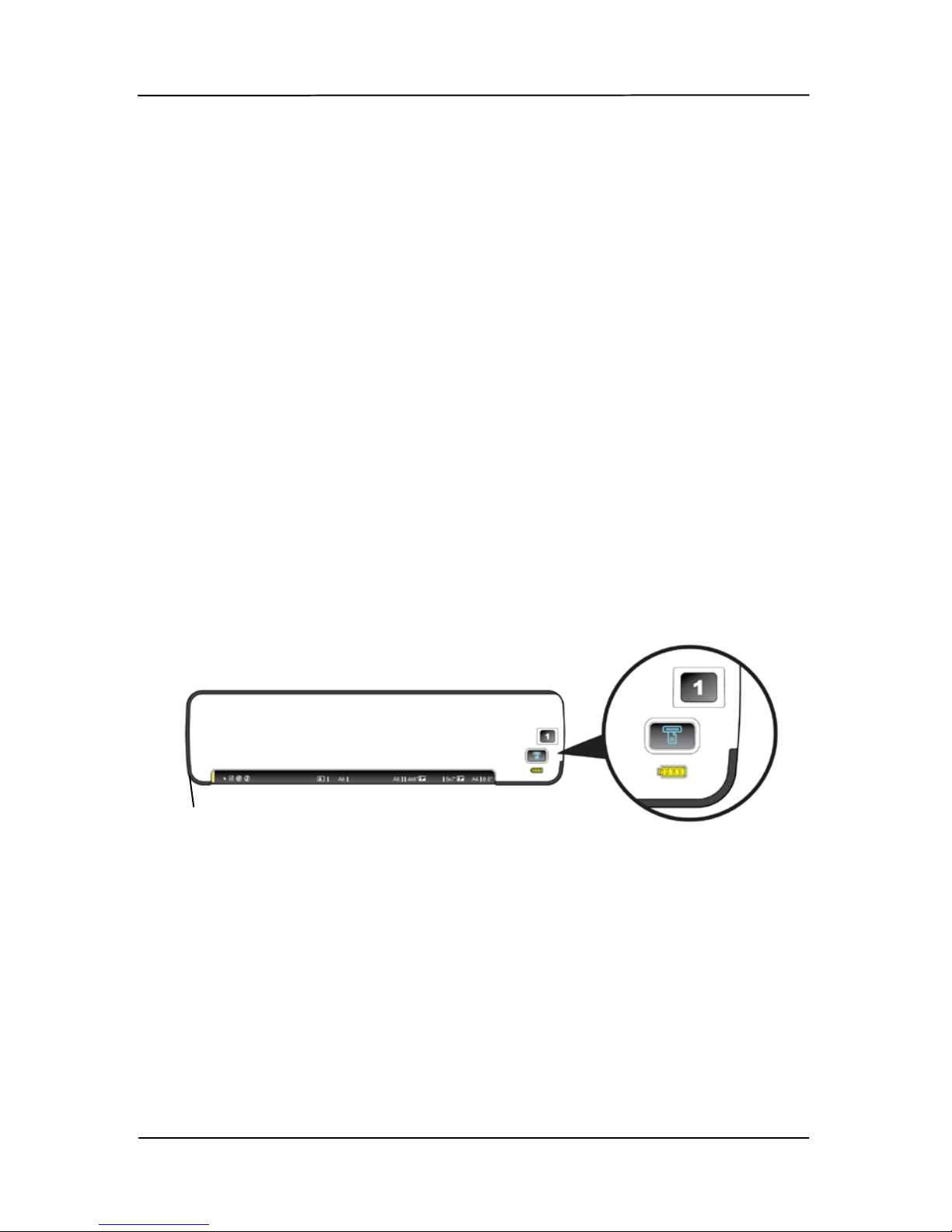
No. Name Function/ Descripti on
1
Power LED and
Knob ( )
Move the knob to “1” ~
“5” to turn on and “OFF”
to turn off the scanner.
2
Scan or Custom
Button (
)
In “SD/Flash” Mode:
Press the button for 2
seconds to start
calibrating the scanner.
In “PC” Mode: Press to
start a s c an.
3
Battery LED
( )
Indicate the battery
status.
Green LED: Indicates
the ready status.
Orange LED: Indicates
the power charging
status.
Red LED: Indicates the
power capacity is in low
status (about 20%).
4
1
2
5
1
2
3
Page 14

User’s Manual
2-2
4 Feeding Slot
Insert an original to
start scanning.
5 System LED
Green LED: Indicate
the ready status.
Green Blinking:
Indicate the scanning
and saving status.
Red Blinking: Indicate
the following status:
• No SD card/Fl as h
drive inserted
• SD card/Flash drive
Memory full
• Wrong SD Card.
Page 15

User’s Manual
2-3
2.2
Side view
6
Glass Release
Button
Press the button t o release
the glas s and to perform
cleaning. (see secti on 8 -2,
Cleaning the scanner
glass)
7
Mini USB
connector
Connect the scanner to a
computer v ia a USB Y
cable for data transmission
and batte r y c harge.
8
USB Flash
Drive Slot
Insert a USB flash drive.
9
Memory Card
Slot
Insert a memory card.
6 7 8 9
Page 16

User’s Manual
2-4
2.3 Rear view
10 PC Mode
Move t o “PC” mode to connect
the scanner to a computer via
the mini USB cable and use the
scanner like a regular scanner.
11
SD/Flash
Mode
Move to “SD Flash” mode to
start instant scan and save your
scanned images to a SD card or
a USB flash drive.
10 11
Page 17

User’s Manual
3-1
3. Installation & operation
in easy mode (SD/Flash
mode)
Precautions
• Keep the produc t out of direct sunlight. Direct
exposure to the sun or excessive heat may cause
damage to the unit.
• Do not install the product in a humid or dusty place.
• Place the pr odu c t securely on an even, flat surface.
Tilted or uneven surfaces may cause mechanical or
paper-feedin g problems.
• Retain the product box and packing materials for
shippi ng purposes.
To start instant scans from this scanner - to scan and save
your images to a SD card or a USB flash drive, you need to
first install and charge the battery. Follow these steps to
charge the battery from your computer.
Important:
Allow the battery to charge for at 6 hours. The battery
must be fully charged before using the scanner for the
first time.
Do not turn on the scanner power when charging the
battery.
Page 18

User’s Manual
3-2
3.1 Inserting the battery
The battery comes pre-installed in the scanner’s battery
compartment. Simply turn the scanner over and remove the
protective tape from the battery compartment.
If the battery is not pre-installed in your unit, or if you need to
replace the battery for any reason, please follow these
instructions for installing the battery.
To install the battery into the scanner,
1. Open the battery cover underneath the scanner.
2. Load the battery into the battery compartment. Make sure
the battery is loaded with the correct polarity. Note the
copper strips on the battery should be touching the
copper strips on the device inside the battery
compartment.
Page 19

User’s Manual
3-3
Note:
Only use the battery model provided with the scanner (NP120
for 3.7V 1700mAh).
Page 20

User’s Manual
3-4
3.2 Charging the battery from t he a d a p t er or the
computer
1. Turn off your scanner by moving the “POWER” knob to the
“OFF” position.
To charge the battery from the comput er, please follow these
steps:
a. Connect the mini end of the supplied USB Y cable to the
mini USB connector of the scanner.
b. Turn on your computer, and then connect the other two
rectangle ends of th e USB cable to two USB port s on your
computer.
Page 21

User’s Manual
3-5
Or
To charge th e battery from the supplied power adapter, pl e as e
follow these steps:
a. Connect the mini USB conn ector of the supplied power
cable to the mini USB port of the scanner.
b. Connect the other end to a power ou tle t.
2. During the charging process, the battery LED light will be
lit in orange. When the power capacity is full, the battery
LED light will be lit in green.
Page 22

User’s Manual
3-6
Note:
• One end of the supplied USB Y cable includes two USB
connectors (one labeled “Power Cable”, the other labeled
“Data Cable”). If only one USB port is available from
your computer, please plug the conn ector labeled “Power
Cable” to your computer while charging the battery and
plug the connector labeled “Data Cabl e” to your
computer while downloading the images. If th ere are two
USB p orts available, it is recommended to plug these two
connect ors to your computer.
• Use the supplied USB Y cable only to this scanner. Using
this USB Y cable to other devices may cause unexpected
damage.
• If the battery is fully charged, an A4-size page can be
scanned in c olor for 200 times.
• If there is not en ough batt ery power t o p erform a sca n,
the system LED will be flashing in red color.
Page 23

User’s Manual
3-7
3.3 Inserting a memory card or a USB flash drive
Insert a memory card with the copper strips facing down in
the SD slot.
Or
If you have a USB flash drive, you can connect it to the USB
port of the scanner.
Page 24

User’s Manual
3-8
Note:
1. Si n ce t h e suppli ed memory card contains scanner driver
and user’s manual, before using the scanner for the first
time, it is recommended to backup the files in case they
will be deleted by accident.
2. As t h e TIFF fil e consumes larger disk space, the speed to
save the TIFF files may vary due to the type of your USB
flash drive and memory card.
Page 25

User’s Manual
3-9
3.4 Turning on the scanner
1. Move the POWER knob to any number between “1” and
“5” to turn on the scanner.
2. The System LED will be first lit in red and then lit in
green steadily. This indicates the scanner is in ready
status.
Important:
• If the scanner is connected with a power adapter or is
connected to your computer with a USB Y cable, the
scanner automatically enters into power saving mode after
idle for 2 minutes. If the scanner is inactive for 3 hours in
the power saving mode, the scanner automatically shuts
down.
• If the scanner is getting its power from a battery without
connecting to a power adapter or a USB Y cable, the
scanner automatically powers off after inaction for 2
minutes. To resume from the idle status, press the Scan
button ( )on the scanner.
The System
LED
Page 26

User’s Manual
3-10
3.5 Scanning an original
1. To start easy mode to save your images to your SD card
or USB flash drive, please turn the operation mode to
“SD/Flash” at the rear of the scanner as indicated.
2. If you wish to save your images to JPEG file format, turn
the POWER knob to “1”.
To save images to PDF file format, turn the POWER knob
to “2”.
To save your images to TIFF file format, turn the POWER
knob to “3”.
To customize the default settings, please refer to
3.7
Customizing Scan Settings.
Page 27

User’s Manual
3-11
3. Insert your document
FACE UP into the feeding slot.
4. Align your document to the left edge of the feeding slot
as indicated.
5. Th e scanner starts scanning the original when the paper
has been fed into the f eedi ng slot.
6. If the output file format is preset to JPEG, the scanner
will automatically create a folder titled “DCIM” and its
subfolder “100Photo” on your memory card or USB
flash drive, which will hold the first 9999 scans. Then
“101Photo” folder will be added for the next 9 999 scans,
and s o on.
Page 28

User’s Manual
3-12
If the output file format is preset to PDF, the scanner will
automatically create a folder titled “DCIM” and its
subfolder “100DOC” on your memory card or USB flash
drive, which will hold the first 9999 scans. Then
“101DOC” folder will be created for the n ext 9999 scans,
and s o on.
(Each scanned image is given a file name with the prefix
IMG/DOC followed by an underline and a 4- digit
sequential n umber in the order th e i m ages are stored.
For example, IMG_0001.jpg,
IMG_0002.jpg/IMG_0001.pdf, IMG_0002.pdf, etc.)
Note:
• If the memory card is near full (lower than 1MB), the
indicator light blinks.
• Use another card or delete some files on it if
necessary.
• Insert only one original at a time, and insert the next
original only when the previous one is done and the
blinking has stopped, otherwise the scanner may
malfunction.
• Remove the things remained on the photo, such as
staples, paper clips, and paper sticky notes before
feeding it into the scanner due to possible damage to
the scanner.
Page 29

User’s Manual
3-13
3.6 Turning off the scanner
After all originals are scanned, turn the POWER knob to “OFF”.
Now you can safely remove the memory card or flash card
from the scanner.
Important!
1. In sert only one page or one photo at a time, and insert
the next one only when the previous one is done.
Otherwise, the scanner may malfunction.
2. The paper detector is quite sensitive. Please do not push
your p hoto or card into the feeding s lot or the top of your
image will be cut. Simply let go the photo (card) when it
begins to feed into the slot.
3. The acceptable paper s ize is 2”x 2” (64 x 64 mm) ~ 8.5”
x 11.7” (216 x 297 mm).
4. Do not use the following types of originals for scanning;
otherwise the scanner may malfunction or cause the
original to jam in the slot.
• Originals thicker than 1.25 mm
• Originals with either side shorter than 55mm
• Originals with lots of black or dark colors
• Originals with dark colors surrounding the edges
• Transparencies(filmstrips, celluloid, etc.)
• Pr inted i m age s (pictur es on newspapers, magazines,
etc.)
• Soft and thin materials (thin paper, cloth, etc.)
• Originals that exceed the acceptable size
Page 30

User’s Manual
3-14
5. The scanner has a bu ilt-i n cropping function that is
capable to detec t and crop the edges of an original. The
max cropping size is 1.5mm per edge, as illustrated below:
Max. 1.5mm
Max. 1.5mm
Page 31
User’s Manual
3-15
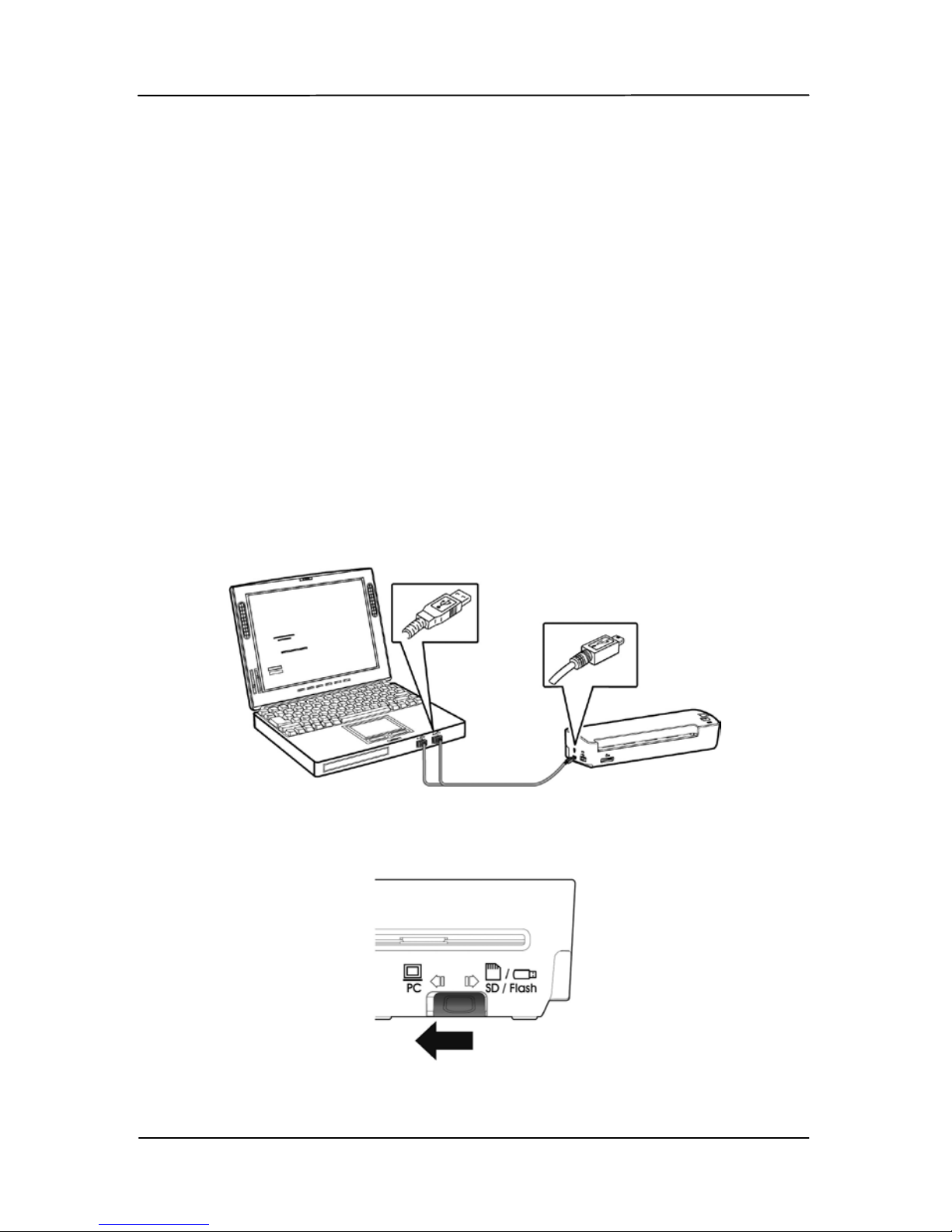
3.7 Customizing scan settings
By default, your original is scanned in 300 dpi with the
functions of auto crop and deskew (auto straighten). The
default scan settings can be customized to fit different
scanning tasks. Please start the Button Function Settings tool
to customize the scan settings for various applications. The
Button Function Settings tool is included in the scanner driver.
Please install the scanner driver in the supplied micro SD card.
3.7.1 Starting the Function Setting Tool
To start the Button Function Settings tool,
1. Connect the scanner to your computer via the supplied
USB cabl e .
2. Move the operation mode at the back of th e s can n er to
“PC”.
Page 32
User’s Manual
3-16
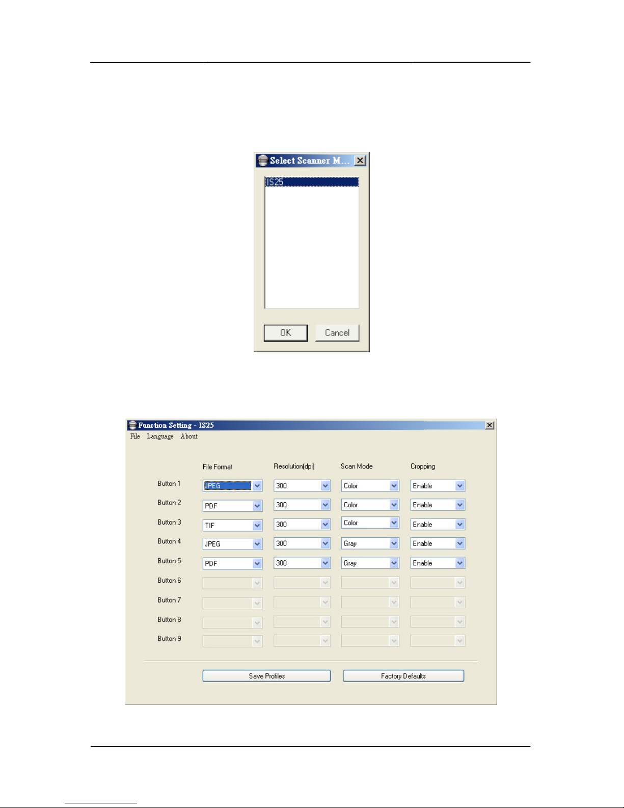
3. Click the Start menu and then choose Programs>Avision
IS25 Scanner>Button Function Setting tool. The S elect
Source dialog box appears.
4. Sel ect your scanner model and choose “OK”. The main
user interface will be displayed.
Page 33
User’s Manual
3-17
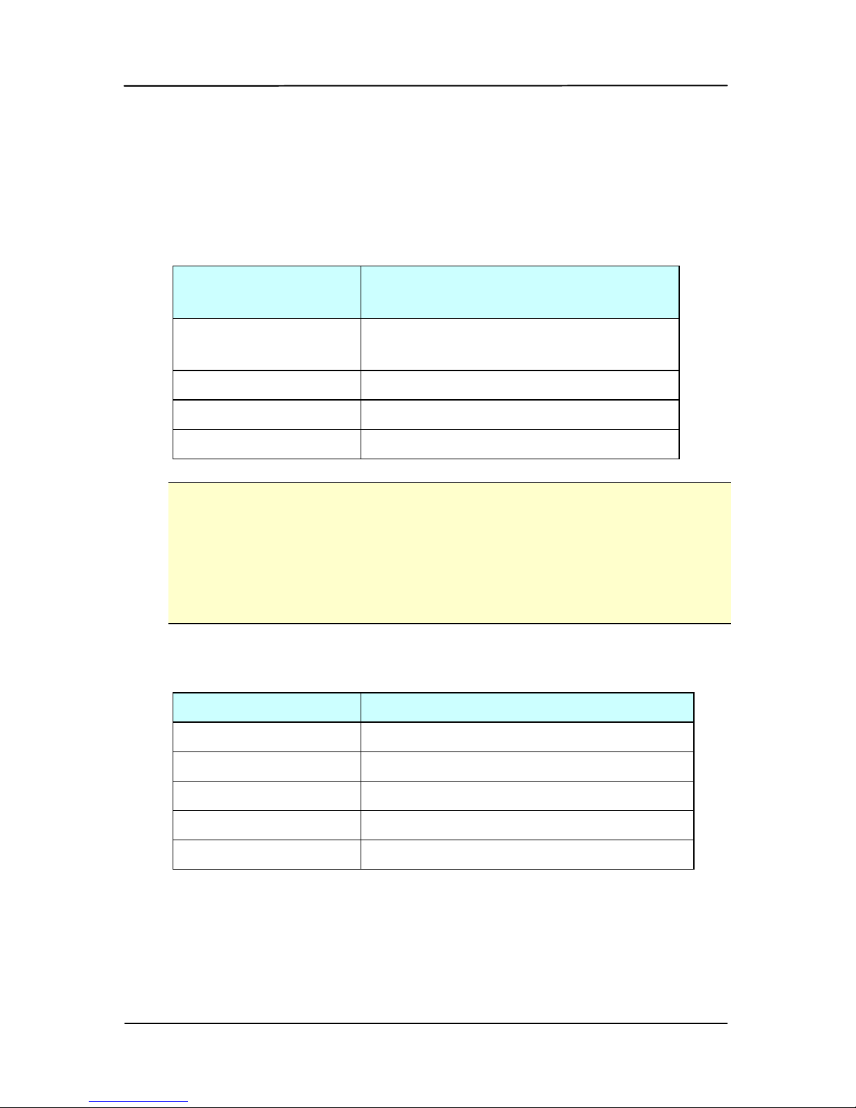
5. Choose your desire d set ting from each of the drop-down
list box.
5 sets of profiles (buttons) can be specified with the
parameters of file format, resolution, scan mode, and
cropping.
Name of
Parameter
Choice
File Format JPEG, TIF, PDF, MPDF (multi-
page)
Resolution 100, 200, 300 dpi
Scan Mode Color, Gray , B&W
Cropping Enable, Disable
Note:
Black and White mode does not support JPEG images.
Only color and gray modes can be applied to JPEG file
format.
Deskew (auto straighten your images) is included in
the Cropping function.
Default Settings
Name of Button Default Scan Settings
Button 1
JPEG, 300 dpi , Color, Auto C rop
Button 2
PDF, 300 dpi, Color , Auto Crop
Button 3 TIF, 300 d p i, Col or, Auto Crop
Button 4 JPEG, 300 dpi, Gray, Auto Crop
Button 5 PDF, 300 dpi, Gray, Auto Crop
6. Af ter your desired settings have been made satisfactorily,
click “Save Profiles” to save your settings.
If desired, click “Factory Defaul t ” to resume all profile to
default settings.
Page 34
User’s Manual
3-18
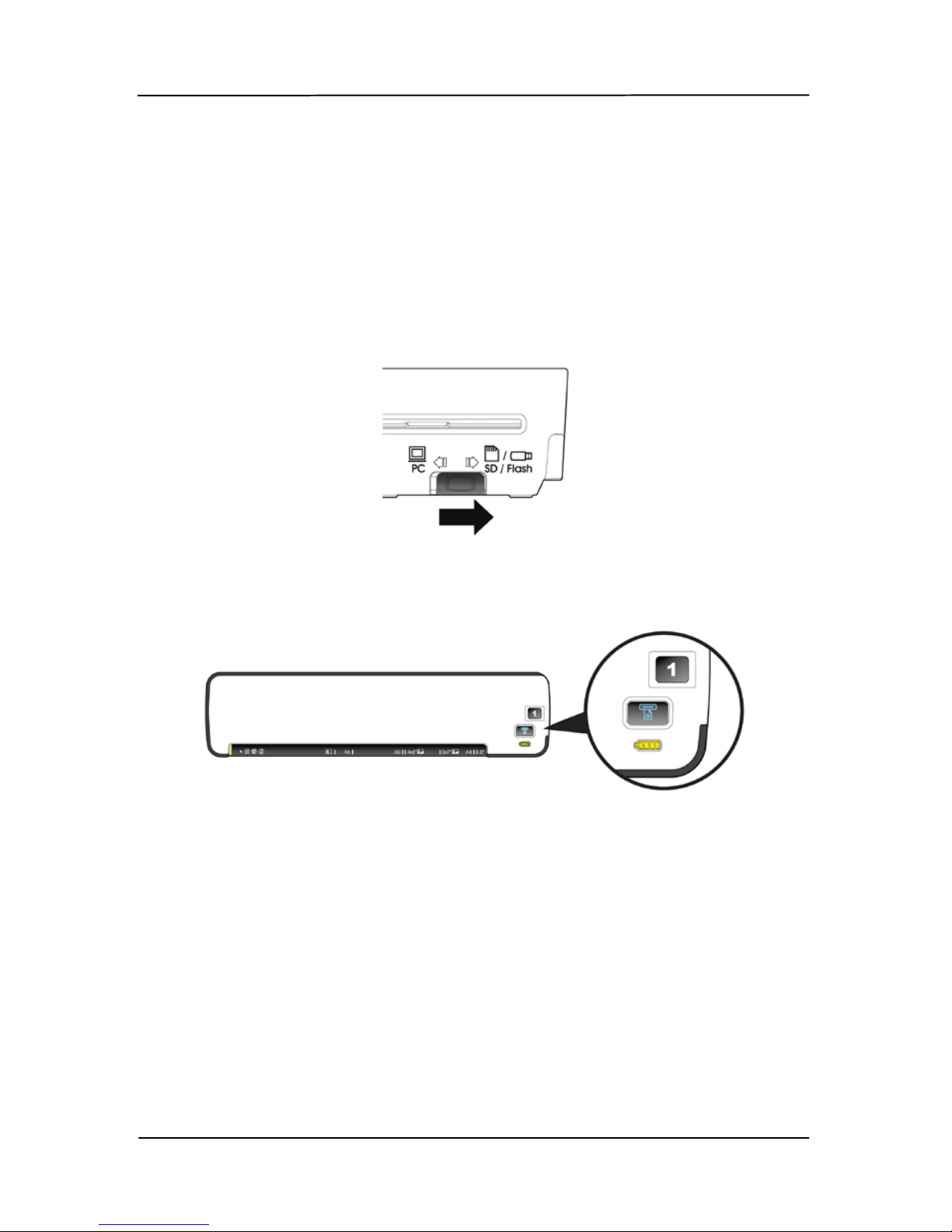
3.7.2 Using the customized scan set tings
To use the customized scan settings,
1. Turn on the scanner by m ovin g the Pow er kn ob to any
number between “1” and “5”.
2. Move the ope ration mod e switch at the back of the
scanner to “SD/Flash”.
3. Move the Power switch to your desired number which
specified the scan profile. For example, profile nu m ber 1.
4. Insert your original to the feeding slot.
5. The scan will be automated started using the specified
settings.
Page 35

User’s Manual
4-1
4. Installation & operation
in advanced mode (PC
mode)
By switching to the “PC” mode, installing the scanner driver and
connecting the scanner to a computer, you can scan via the
TWAIN user in terface from your image-editing software
application and enhance your image quality with various
features.
4.1 Installing t he Scanner Driv er and Cables
NOTE:
1. The Windows system CD may be required when installing
on som e PC’s.
2. To ensure your computer can identify the USB scanner,
please install scanner driver first before connecting the
scanner to your computer.
3. The scanner driver contains both TWAIN driver and WIA
driver. If you are running Windows XP, or Windows Vista,
after the installation of scanner driver is completed, this
scanner allows you to scan via a TWAIN user interface or a
WIA (Windows Image Acquisition) interface. Start your
TWAIN-compatible image editing software application to
select a TWAIN or WIA user interface. Or you might launch
Microsoft’s Scanner and Camera Wizard to scan via a WIA
user interf ace.
Page 36

User’s Manual
4-2
4.1.1 Installing the scanner driver
1. Insert the su pplied mi c r o SD car d into your card r eader and
then connect the card reader to your computer.
If a card reader is not available, you can switch the
operat ion mod e to “SD/Flash” temporarily and connect the
scanner to your computer. The computer then is able to
identify your scanner as a “Removable Disk ” an d read y our
files in the memory card.
2. Browse the memory card. You will find a folder “START
HERE” is creat ed. Double click the “setup.exe” file in the
folder. The software installation graphic appears.
Contents on the installation grap hic:
• Install Butt on Manager V2: To use the buttons on
the scanner, you need to install Button Manager V2.
To ensure Button Manager V2 works properly, please
FIRST install Button Manager V2 before installing the
scanner driver.
• Install Scanner Driver: To communicate with your
scanner, you need to install the scanner driver. After
installing the Button Manager V2 software, click
Install Scanner Dri v er to install the scanner driver
on your computer.
Page 37
User’s Manual
4-3
• Install Adobe Read er: To view the user’s manuals
for the scanner and Button Manager V2, you n eed to
use Adobe Reader to open and view the manuals in
PDF file format. If you already have Adobe Reader
installed on your computer, you may disregard this
item.
• View Manual: Click “View Manual” to view or print
the detailed user manual for the scanner and Button
Manager V2 respectively.
3. Click Install Button Manager V2 to install the Button
Manager V2 software and then click Install Scanner
Driver to install the scanner driver on your computer.
4.1.2 Turning on the Scanner
1. Move the POWER knob to any number between “1” and
“5” to turn on the scanner.
2. The System LED will be first lit in red and then lit in green
steadily. This indicates the scanner is in ready status.
The System
LED
Page 38
User’s Manual
4-4
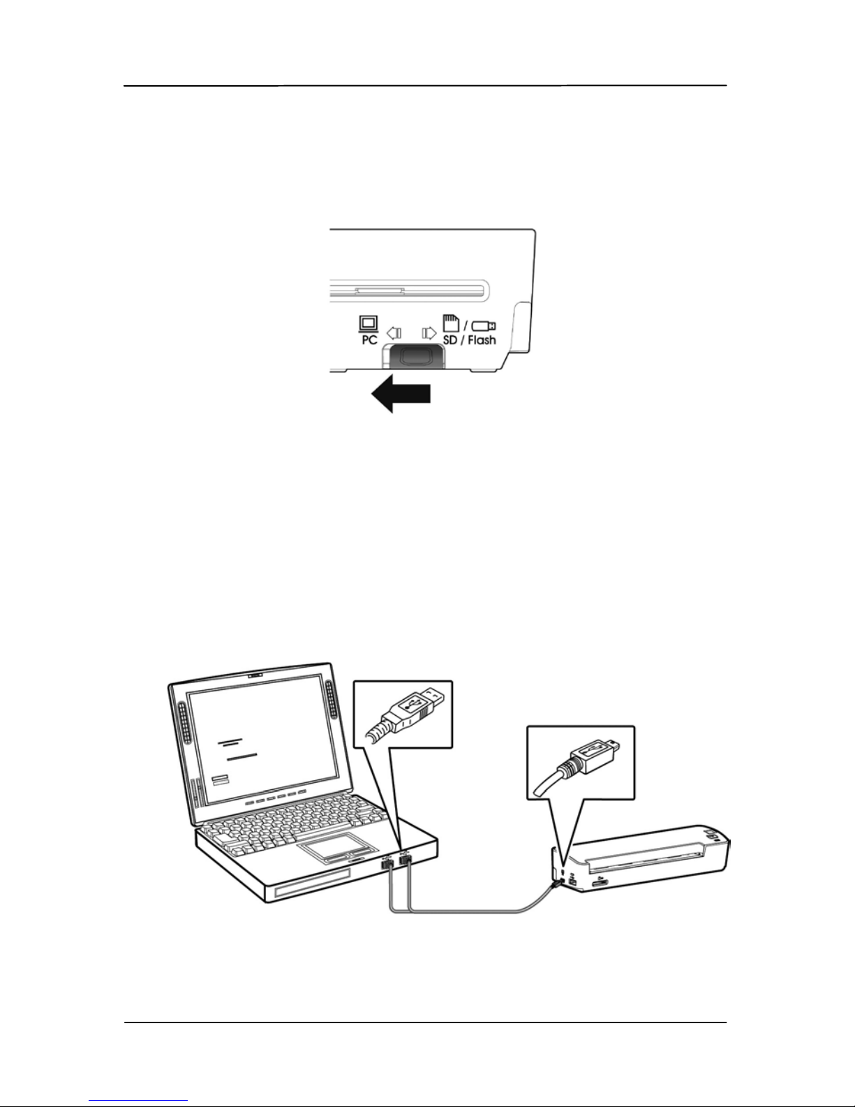
4.1.3 Switching to “PC” mode
Please turn the operation mode to “PC” at the rear of the
scanner as indicated.
4.1.4 Connecting to Computer
The scanner will get its power from the computer through the
USB cabl e . Use the USB cable that came with the scanner to
connect the scanner to the computer.
1. Connect the square end of the USB cable to the USB port of
your scanner. Connect the rectangle end to the U SB port of
your compu ter.
Page 39

User’s Manual
4-5
2. The computer should dete c t a new USB dev ice and prompt
a “New Hardware Found” message.
3. In Windows XP or later, click the Next button to continue.
When the XP certification screen appears, click Continue
Anyway to complete the installation.
In Windows Vista, click the Recommended option, and
then click Continue button to complete the installation.
4. When the Finish dialog is prompted, click the Finish
button.
5. Click “View Manual” to view or print the detailed user
manual for the scanner and bundled applications
respectively.
Page 40

User’s Manual
4-6
4.2 Placing your document
4.2.1 Notice on using the ADF
Before using the A DF, please make sure that your paper meets
the following specifications:
• Document(s) can range in size from 2” x 2” (64 x 64 mm)
to 8,5” x 11.7” (216 x 297 mm).
• Document(s) can range in weight from 9 to 34 lbs (34 ~
127 g/m
2
)
• Plastic ID cad up to 1.25 mm thick
• Document(s) should be square or rectangular and in good
condition (not fragile or worn).
• Document(s) should be free of curl, wrinkl e, tears, wet ink,
or punch holes.
• Document(s) sh ou ld be free of st aples, paper clips, paper
sticky notes.
Page 41
User’s Manual
4-7
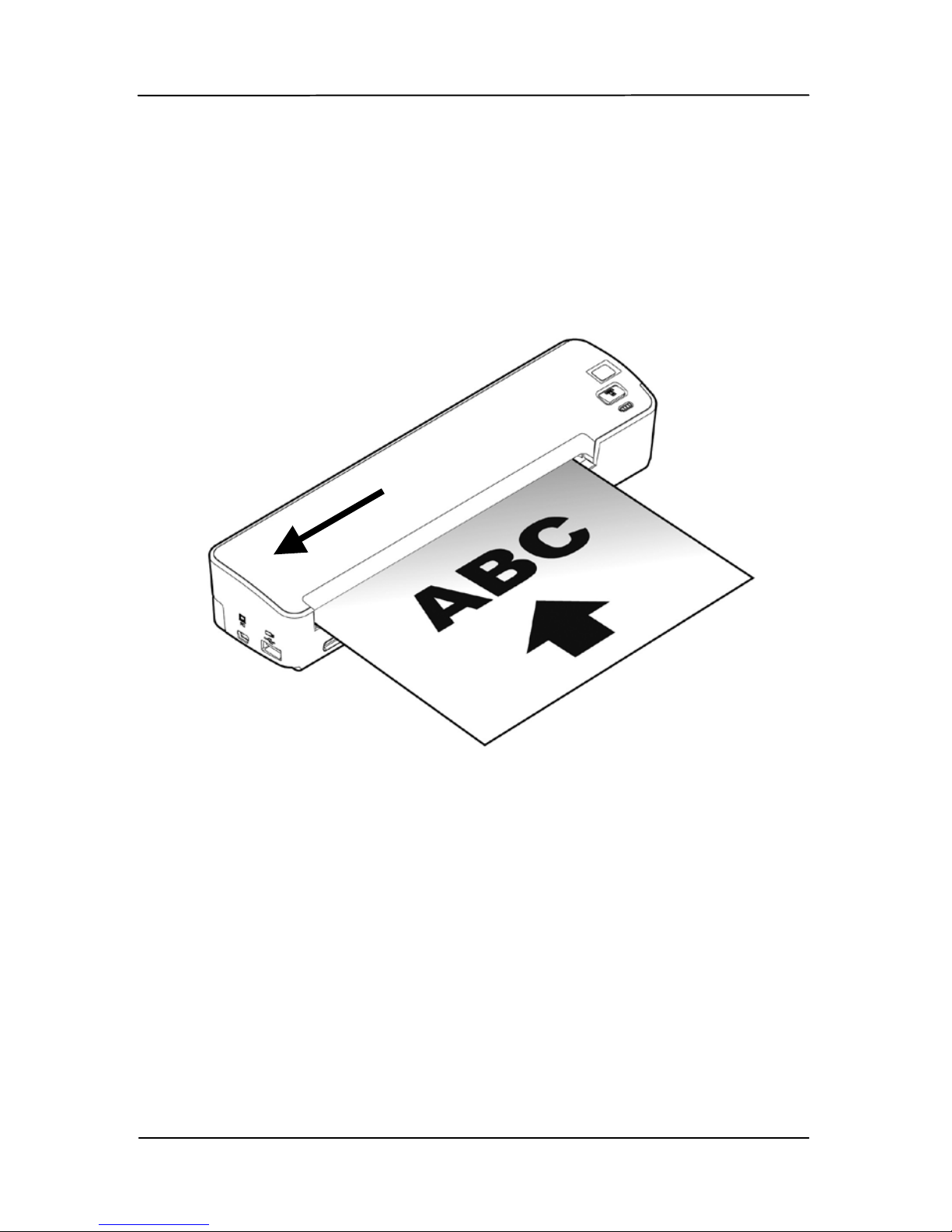
4.2.2 Loading paper to the Paper Feed Sl ot
1. Insert your document facing up to the paper feed slot .
2. Align the original to the left side of the paper feed slot.
Page 42
User’s Manual
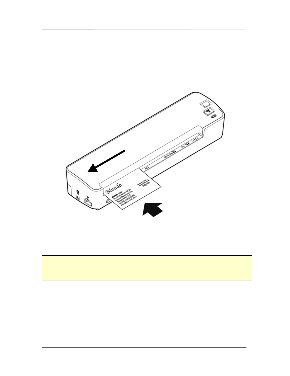
4-8
4.2.3 Loading a card to the Paper Feed Sl ot
1. Place the card face up with the long dimension parallel to
the paper feed slot and make sure the t op of the card
points to the paper feed slot.
2. Align the original to the left side of the paper feed slot.
Note:
This scanner is able to scan plastic ID cards from the f ront input
tray. Plastic ID cards up to 1.25 mm thick.
Page 43
User’s Manual
4-9
4.3 Verifying your scanner installation
To verify if your scanner installation is correct, Avision provides
you a useful test program called Avision Capture Tool. With this
tool, you can perform simple scans and view t he captur ed
images. In addition, it helps you complete your scan at a rated
speed.
The following procedure describes how to verify your scanner
installation. If the installation is not correct, please review the
preceding section to check if the cable connection and scanner
driver have been successfully installed.
Before you begin, be sure the scanner is on.
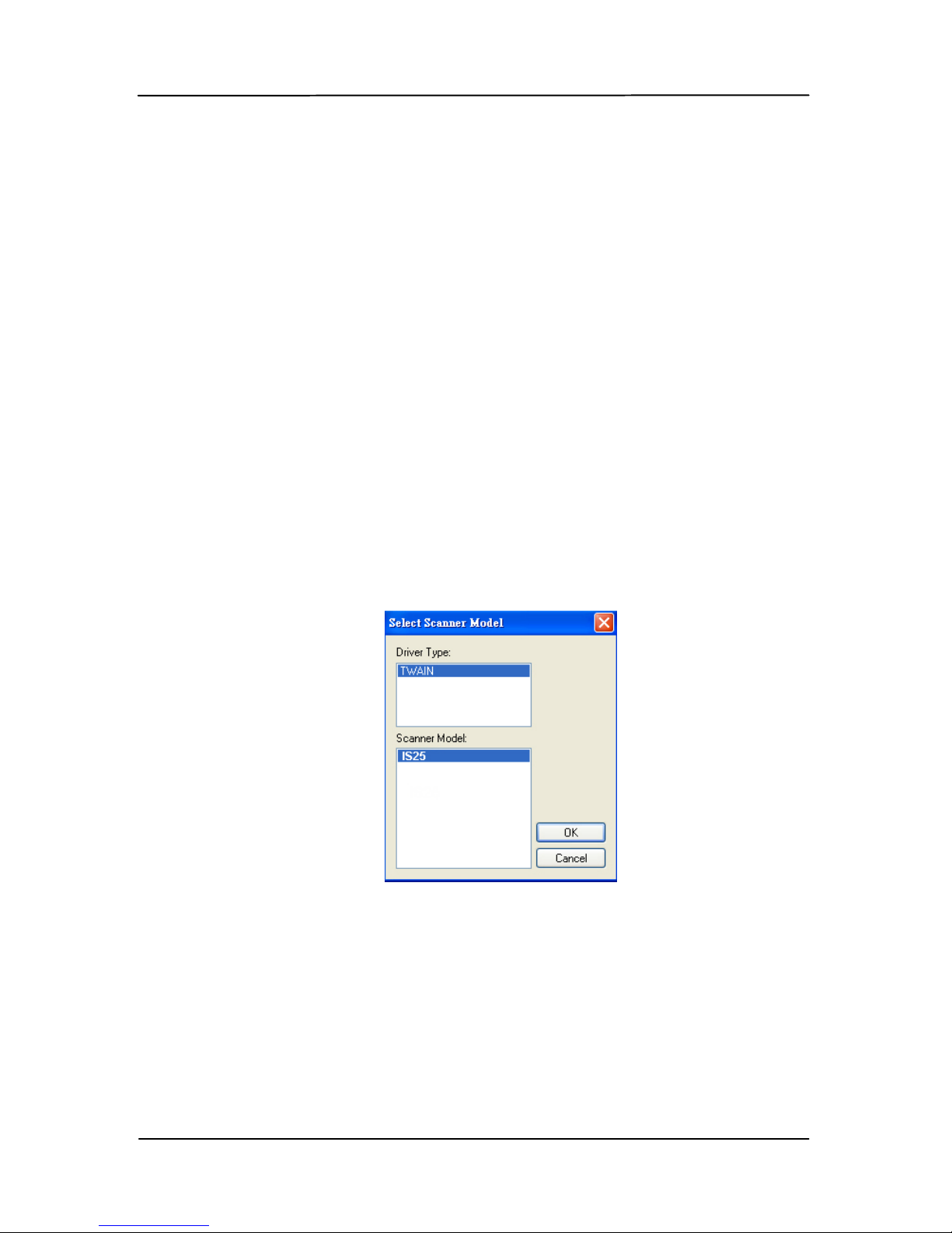
1. Select Start>Programs>Avision IS25 Scanner>Avision
Capture Tool.
The Select Scanner Model dialog box will be displayed.
2. Select your driver type and scanner model and click OK.
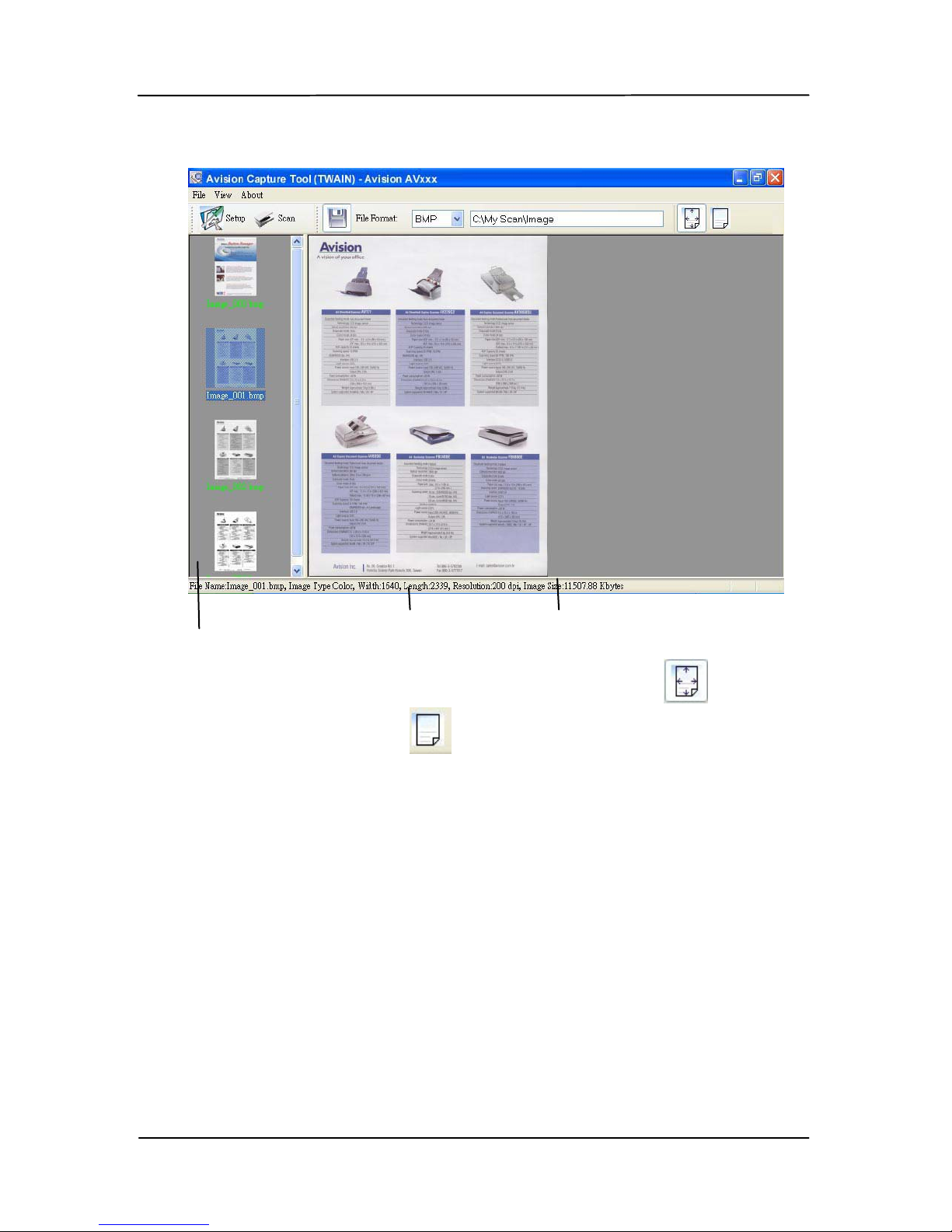
The following Avision Capture Tool dialog box will be
displayed.
Page 44

User’s Manual
4-10
3. Choos e your desired file format from the File Format drop
down list box. (Default is BMP, other choice includes TIFF,
GIF, and JPEG.)
4. Type your desired folder name and fil e n ame i n the File
Path box. (Default is C:\My Scan\Image.)
Note:
If you d o not wish to save th e scanned image, deselect t he
Save button since default is Save Enable. In this case, the
thumbnail view will be disabled. And therefore, after
viewing all the scanned images, only the last one will remain
on the screen.
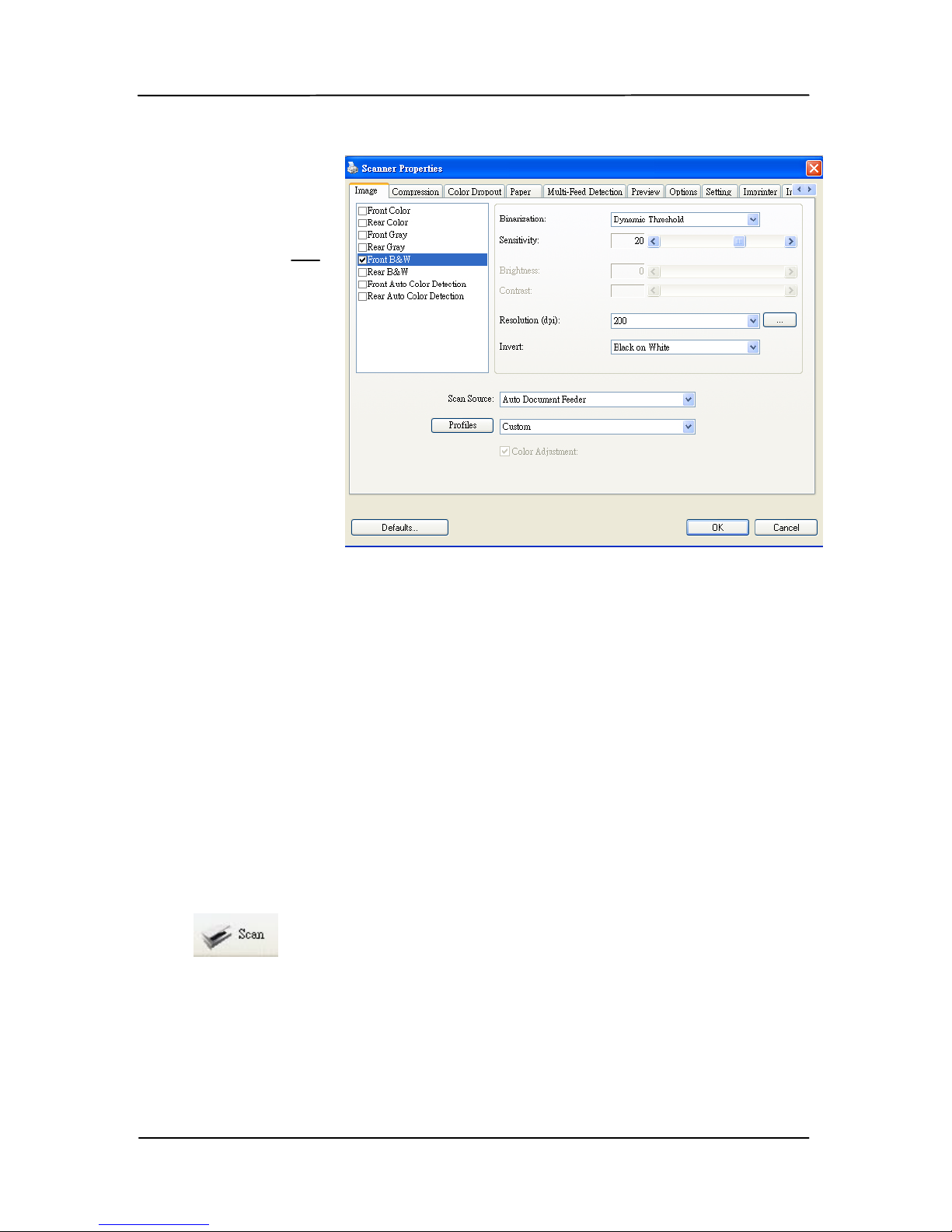
5. Click the Setup button ( ) or ch oose Set up from the
File menu to prompt the Scanner Properties dialog box.
Setup
Actual
Size
Fit Page
Scan
File Format
File Path
Page 45
User’s Manual
4-11
6. From the Image Selection Box, choose your desired image
type for your scanned image. (Default is Front B&W) If
you have a duplex scanner, choose Front and Rear to scan
both side s of your document.
7. Click OK to quit the Scanner Properties dialog box. (To
learn more details about the Scanner Properties dialog box,
please see the subsequent chapter, Using the Scanner
Properties Dialog Box.)
8. Place your document face down on the document glass or
face up in the auto document feeder.
9. In the Scan Validation dialog box, click the Scan button
(
) or choose Scan f rom the File m enu .
10. The document will be scanned and displayed in the Scan
Validation screen. After the scanned images have been
displayed, your scanner installation verification is completed.
Image
Selection
Box
Page 46
User’s Manual
4-12
11. You can view the scanned image in Fit Page (
) or Actual
Size (100%) button (
) from the Viewing toolbars at the
right side.
12. Click the Close box or Quit from the File menu to exit the
Scan Validation Tool.
Fit Page View
Status Bar
Thumbnail View
Page 47
User’s Manual
4-13
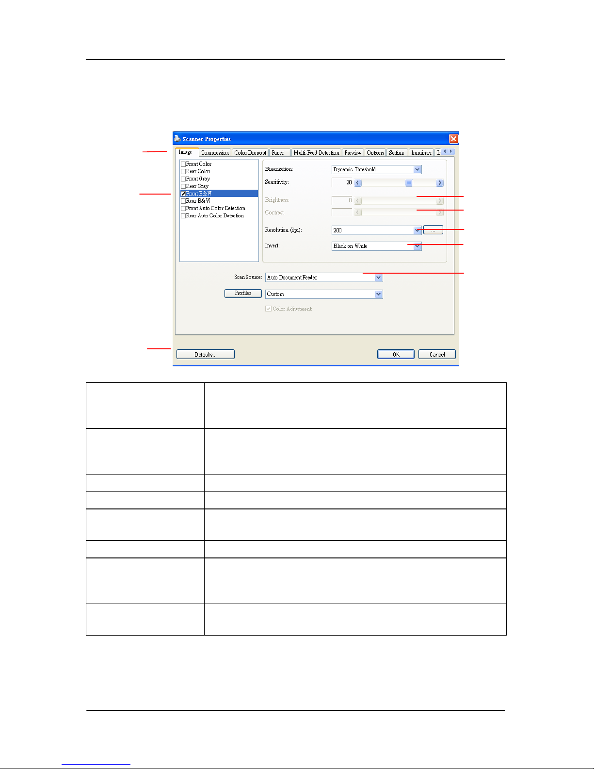
4.4 A glance of the Scanner Prop ert i es Dialog box
1. Tab Options Choice: Image, Compression, Color Dropout,
Paper, Multi-Feed Detection, Pr eview, O pt ions,
Settings, Information.
2. Image
Selection Box
Choose y our im ag e t ype and the side of
document you wish to scan. Optio n s vary based
on type of scan n er .
3. Brightness Adjust the brightness level from –100 to +100.
4. Contrast Adjust the contrast level from –100 to +100.
5. Resolution
Determine the qu ality of the sca n n e d image. Th e
industry sta ndar d is 200 dpi.
6. Invert Reverse the color of your scanned image.
7. Scan Source Choice: Auto Document Feeder, Flatbed, Flatbed
(Book) , Au to m atic (vari es due to di fferent scanner
model)
8. Defaults Reset all values on the tabs to t h e f acto r y default
settings.
3
4
5
6
7
1
2
8
Page 48

User’s Manual
4-14
4.5 Scan from the scanner button
To scan using the scanner buttons, follow these steps:
1. Load the originals.
2. Press the Scan button (
) to start a scan. The Scan
Progress Window will be di s played and th e s c anned image
will be saved in a default location or a user defined
location.
Page 49
User’s Manual
5-1
5. Enhancing your image
quality with the Scanner
Properties Dial og box
By switching to the “PC” mode, installing the scanner driver
and connecting the scanner to a computer, you can scan via
the TWAIN user interface (Scanner Properties dialog box) from
your image-editing software application and enhance your
image quality with various features.
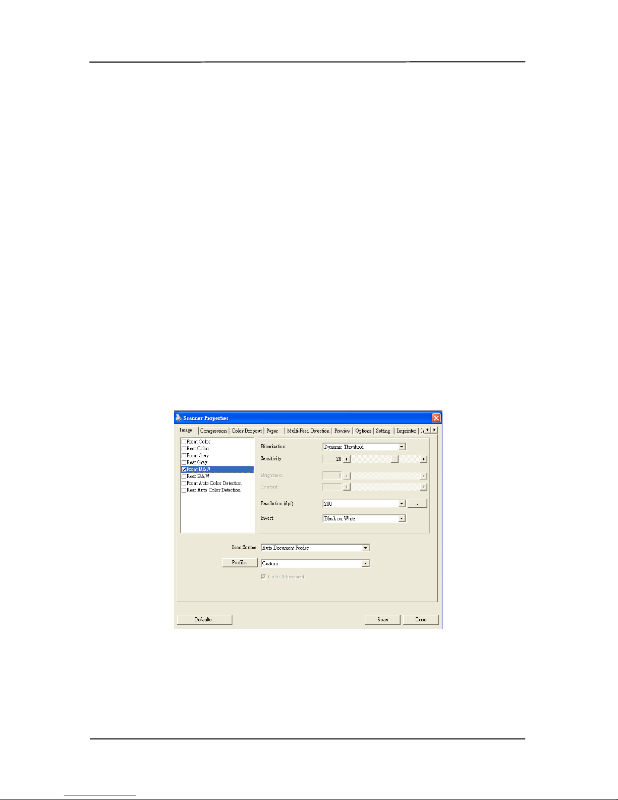
The Scan ner Propertie s dialog box allows you to configure the
scanner’s settings. It consists of several tabbed windows each
of which will be described in this chapter.
The Scanner Properties di a l og box
Page 50
User’s Manual
5-2
5.1 Buttons on the Scanner Properties Dial og box
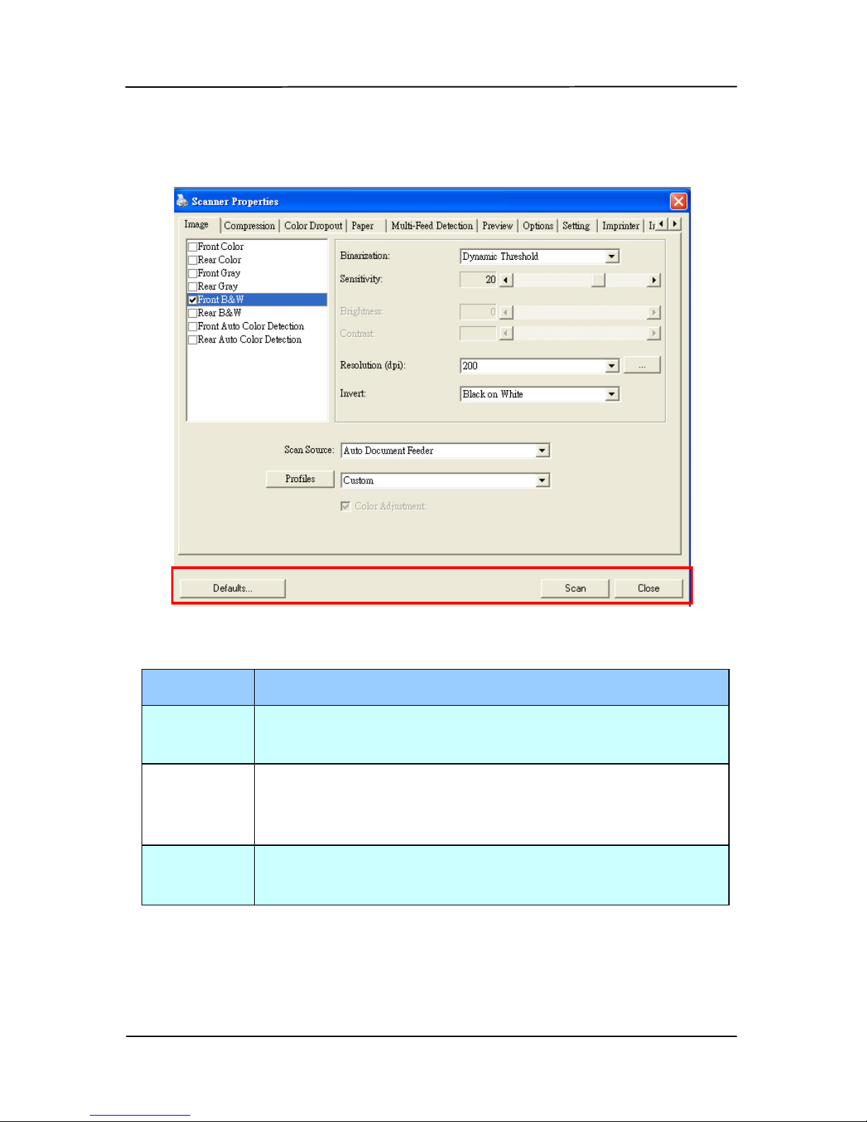
The buttons on the Scanner Properties dialog box
Buttons
Description
Defaults Click the Defaults button, the factory default
settings will be shown on each tab.
Scan After all the scan settings are satisfactory,
click the Scan button to start scanning your
document.
Close Click the Close button to leave the Scanner
Properties dialog box.
Page 51

User’s Manual
5-3
The following table shows the default settings:
Tab name Default settings
Image Image:Front B &W
Binarization:Dynamic Threshold
Resolution:200 dpi
Invert:Blank on White
Scan Source:Auto Document Feeder
Threshold:None
Brightness:None
Contrast:None
Compression None
Color Dropou t None
Paper Cropping:Automatic
Deskew:Yes
Orientation:Portrait
OverScan:0.00
Unit:Inch
Multi-Feed
Detection
None
Preview None
Options Rotation Degrees:None
Blank Page Re m oval:None
Edge Fill:White,0 mm
Image Control Option:None
Setting E n abl e E nergy Saver:Enable, 15
minutes after last scan action
Show Scanning Progress:Yes
Show Warning Message:Yes
Save Settings after Closing:Yes
Imprinter Digital Imprinter
Page 52
User’s Manual
5-4
5.2 The Image tab
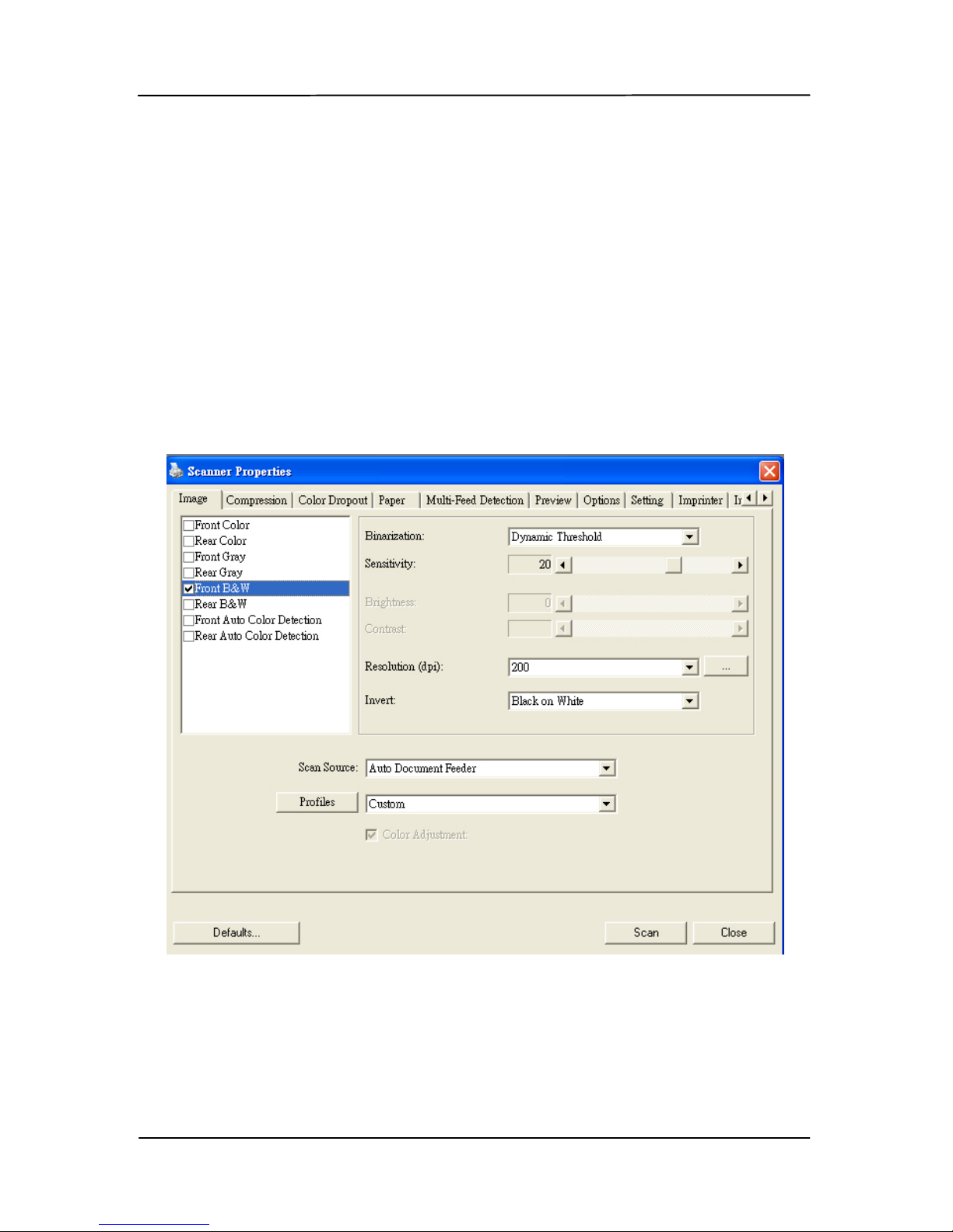
The Image tab allows you to choose the front side and (or) the
rear side of your document, the type of image, and to set
several basic scan settings. Note that except for the
resolution, you can set individual scan settings for the front
side and t he rear side. For example, all settings in the Image
tab, Compression tab, Color Dropout tab can be set
individually for the front and the rear side. However, the
settings in the Paper tab, the Option tab, and the Setting tab
have to be set the same for the front and rear side.
The Image tab dialog box
Page 53
User’s Manual
5-5
5.2.1 The Image Selection box
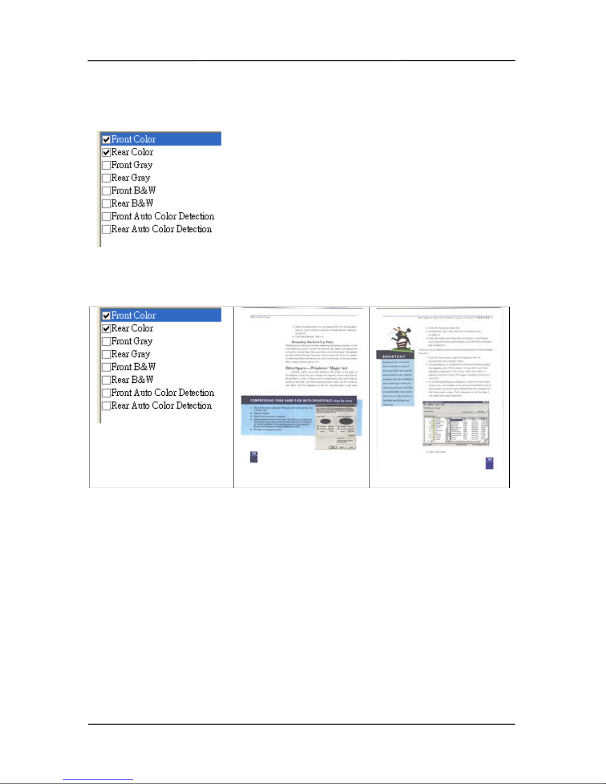
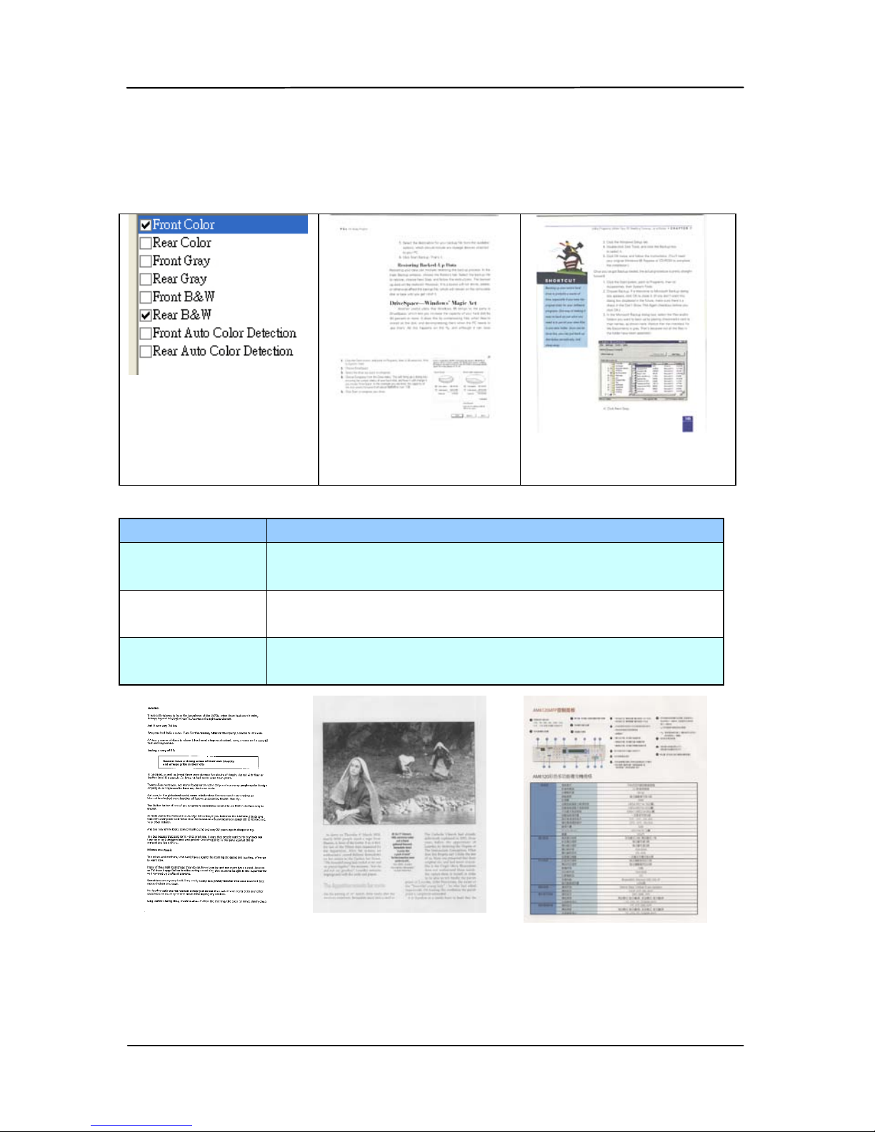
The Image Selection box incl udes the
image type and document side
option. If you wish to scan both the
front side and the rear side of your
color document, you can check both
Front Color and Rear Color at the
same time. Note the options vary
based on type of scanner.
Example 1
:Scanning a two-sided color document, both
sides in color
Side/Image
Selection
Front
Rear
1
Page 54
User’s Manual
5-6
Example 2
:Scanning a two-sided color document, one
in B&W(Drop Blue Color
:Threshold:10, Background:
79), the other in color
Side/Image
Selection
Front
Rear
Image Type
Description
Color Choose Color if you wish to sca n a color
image for your original in color.
Gray Choose Gray image if your original contains
actual s hades of gray.
B&W Choose B&W if your original contains only
text, pencil or ink sketch.
B&W Gray Color
Page 55

User’s Manual
5-7
Front/Rear Auto Color Detection:
Click to automatically detect and scan the front or the rear
page of your color d ocume nt in color i mage mode. If your
document is in colors, the scanner will automatically scan the
document in to a color image. I f your docu ment is non-color,
you can choose the output to be either B&W or Gray from the
Non-Color Selection option. This option is useful when you
have a mixtur e of color and non-color document.
Note: If you choose Front Re a r Auto Color D e tection, you can
not specify the image mode of your rear page and vice versas.
Sensitivity of Auto Color Detection
If your documents contain primarily B&W text and small
amount of light or pale colors and you do not wish them to be
recognized as color image to save the file si ze, you can reduc e
the sensitivity value by moving the bar to the left to let these
images to be detected as B&W. The value ranges from 1 to 30.
The default is 20.
Page 56

User’s Manual
5-8
5.2.2 Other Image options
Binarization
This is the process of converting a
grayscal e or color ima g e to a bi-tonal
image. There are several different
methods of perf orming this conversion.
Options: Dynamic Threshold, Fixed
Processing, Hal ftone 1~ 5, Error
Diffusion.
Dynamic Threshold: Selecting
Dynamic Threshold allows the scanner
to dynamically evaluate each document
to determine the optimal threshold value
to prod uce the highest quality image.
This is used to scan mixed document
containing faint text, shaded background,
or color background with a single setting.
If Dynamic Threshold is selected,
Threshold, Brightness, and Contrast are
not available.
Sensitivity of Dynamic Threshold
Occasionally your scanned image may
contain small dots or speckles. To
remove these spots, increase the
sensitivity value by moving the bar to
the right. The value ranges from 1 to 30.
The default is 20.
Page 57
User’s Manual
5-9
Fixed Processing: Used for black-andwhite and other high contrast documents.
A single level is set to determine the blackand-white transition. The threshold is
programmable over the entire density
range. Fixed Processing sets Contrast to
0. If Fixed Processing is selected,
Contrast is not available.
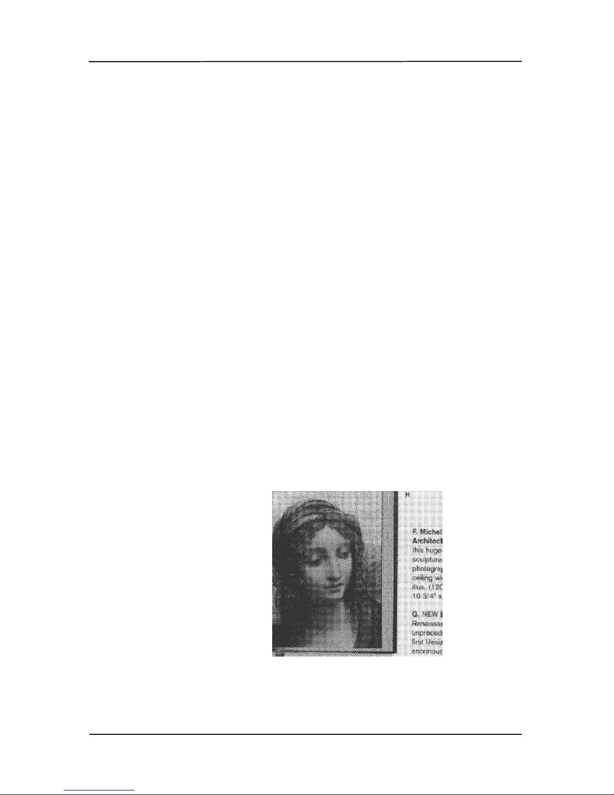
Halftone: In addition to the black and
white display, Halftone can present a
somehow gray shade of i mage by using
different size of dots. Halftone image looks
like the pi cture we have seen in the
newspaper. Options include Halft one 1,
Halftone 2, Halftone 3, Halftone 4,
Halftone 5.
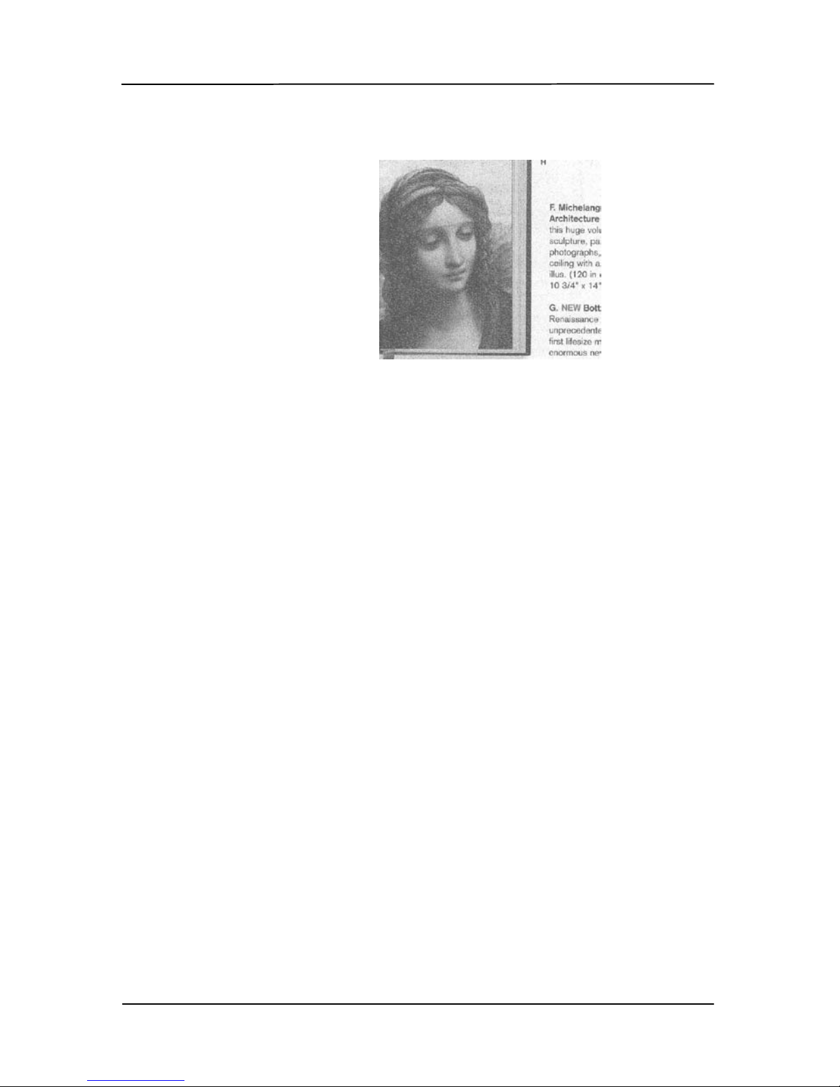
Error Diffusion: Error Diffusion is a type
of Halftone. Error Diffusion give s good
image texture and makes text in images
more readable than Halftone .
Halftone Image
Page 58
User’s Manual
5-10
Error Diffusion Image
Page 59
User’s Manual
5-11
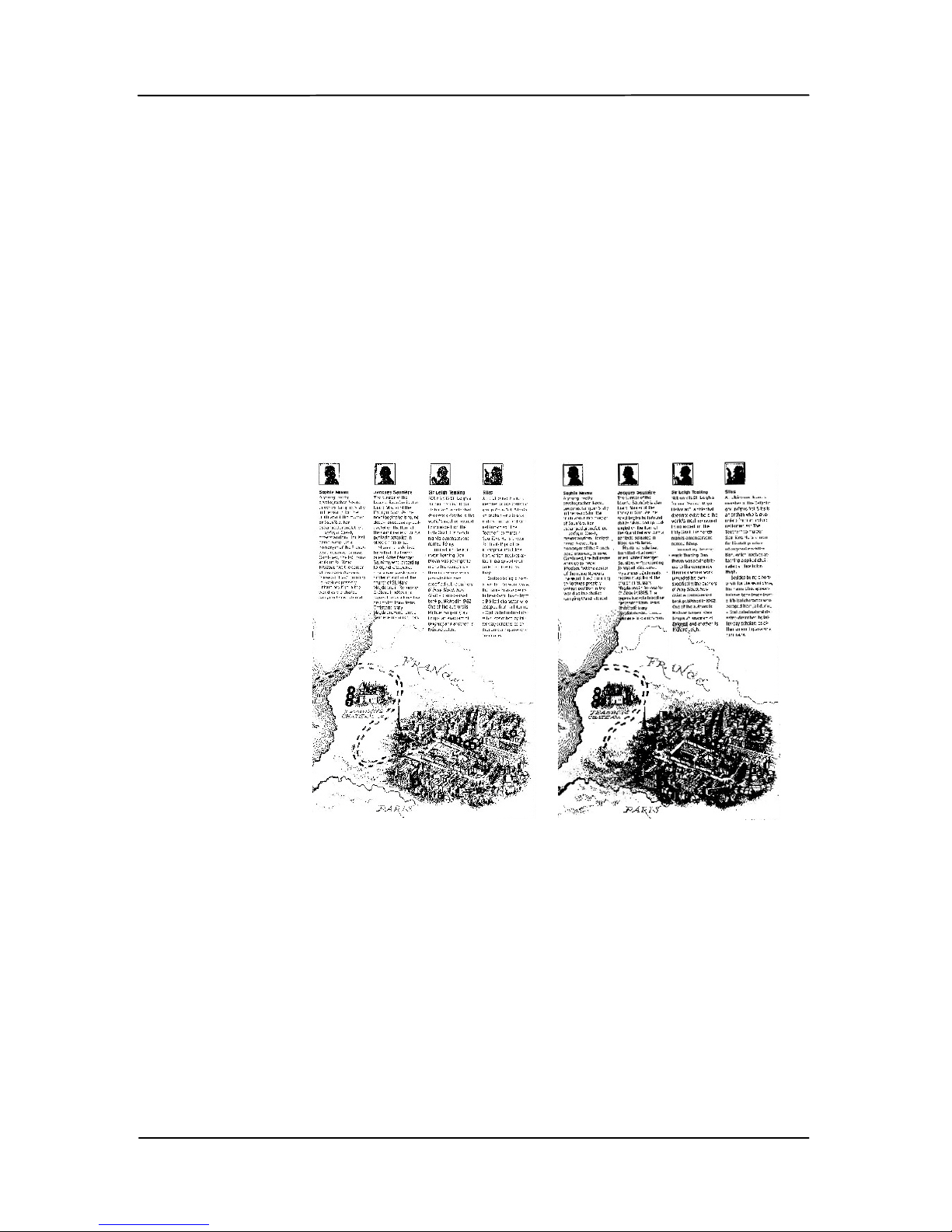
Threshold Used to convert a grayscale image to a
bi-tonal image. The value ranges from 0 to
255. A low threshold value produces a lighter
image, and can be used to subdue
backgrounds and subtle, unneeded
information. A high threshold value produces
a darker image, and c an be used to h elp pick
up faint images.
Adjust the threshold setting by dragging the
Threshold sliding bar to the left or right to
achieve the desired threshold setting.
200 dpi,
Threshold:50,
Brightness: 0
200 dpi,
Threshold:100,
Brightness: 0
Page 60

User’s Manual
5-12
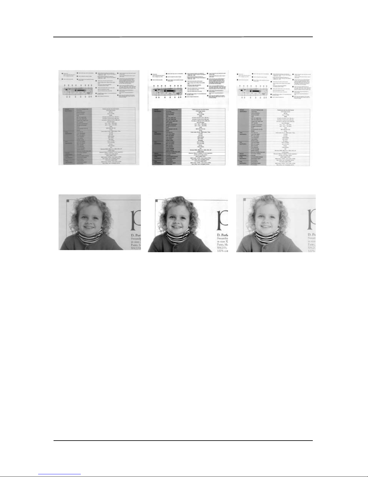
Gray
Document Type: Choice: Norma l, Photo, Document
Thr ee options of docu ment type are p rovid ed when you choose
Gray as the image type for your scanned document. Choice:
Normal, Photo, Docu ment.
• Document: Choose Document if your original contains
pure text or a mixture of text and graphic since it is an
optimal setting for regular business document. When
using Document, only Threshold can be adjusted.
• Photo: Choose Photo if your original c ontains p hoto to
reproduce your photo in vivid grayscale image. When
using Photo, no Threshold and Contrast can be adjusted.
• Normal: When using Normal, Threshold, Brightness,
and Contrast can be adjus ted.
Threshold: The value ranges from 0 to 255. The default is
230. A low threshold value produces a lighter image, and can
be used to su bdue backgrounds and subtle, unnee ded
information. A high threshold value produces a darker image,
and can be us ed to help pick up faint images . A dju s t the
threshold sett ing by dragging the Threshold sliding bar to the
left or right to achieve the desired threshold setting.
Page 61
User’s Manual
5-13
Normal
Photo
Document
(Threshold: 230)
Normal
Photo
Document
(Threshold: 230)
Page 62
User’s Manual
5-14
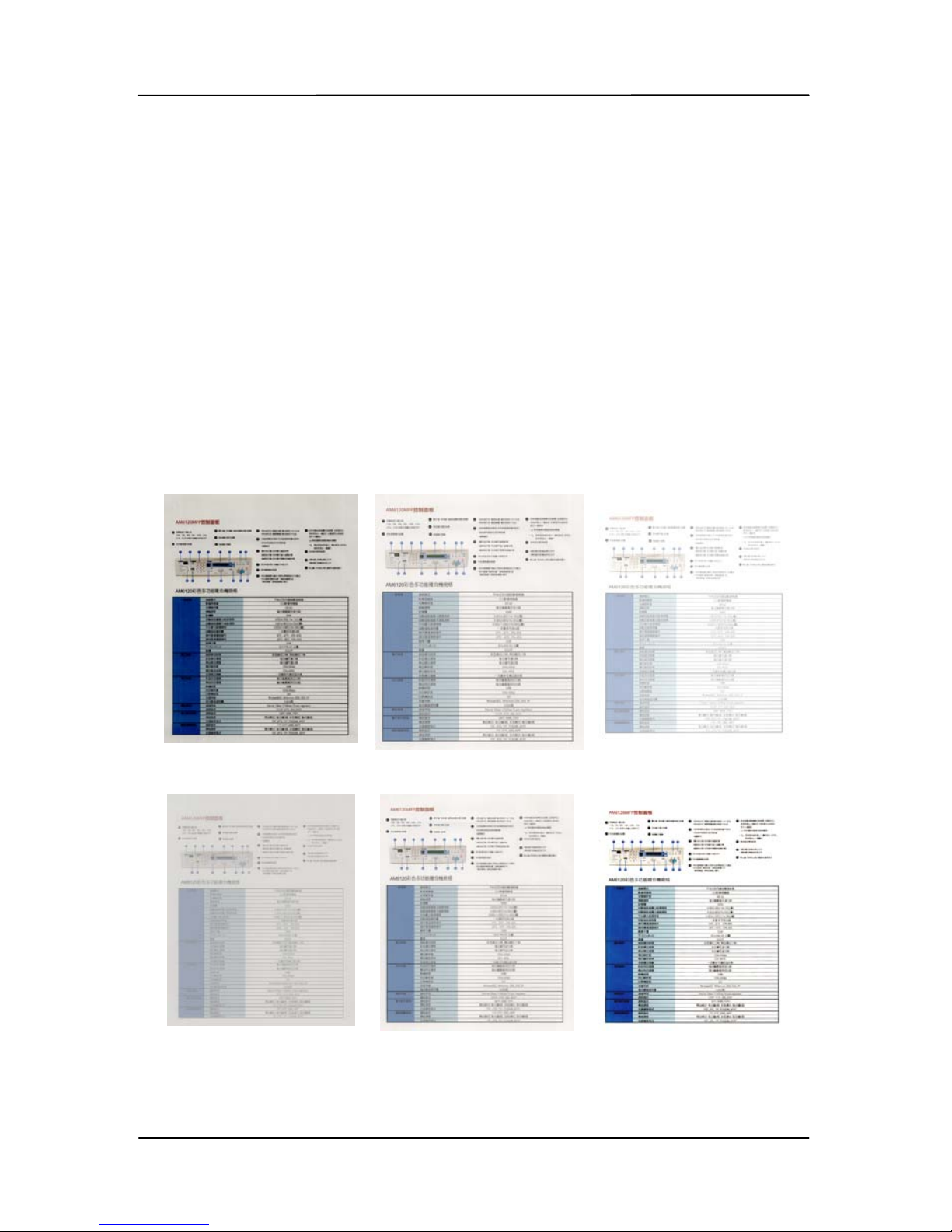
Brightness
Adjusts the lightness or darkness of an
image. The higher th e val ue, the brighter
the image. Drag the slider to the right or
left to incr ease or decrease the
brightness.
The range is from –100 to
+100.
Contrast
Adjusts the range between the darkest
and the lightest shades in the image. The
higher the contrast, the bigger the
different grayscale. Drag the slider to the
right or left to increase or decrease the
contrast.
The range is from –100 to +100.
Brightness: -50 Brightness: 0
(Normal)
Brightness: +50
Contrast: -50 Contrast: 0
(Normal)
Contrast: +50
Page 63
User’s Manual
5-15
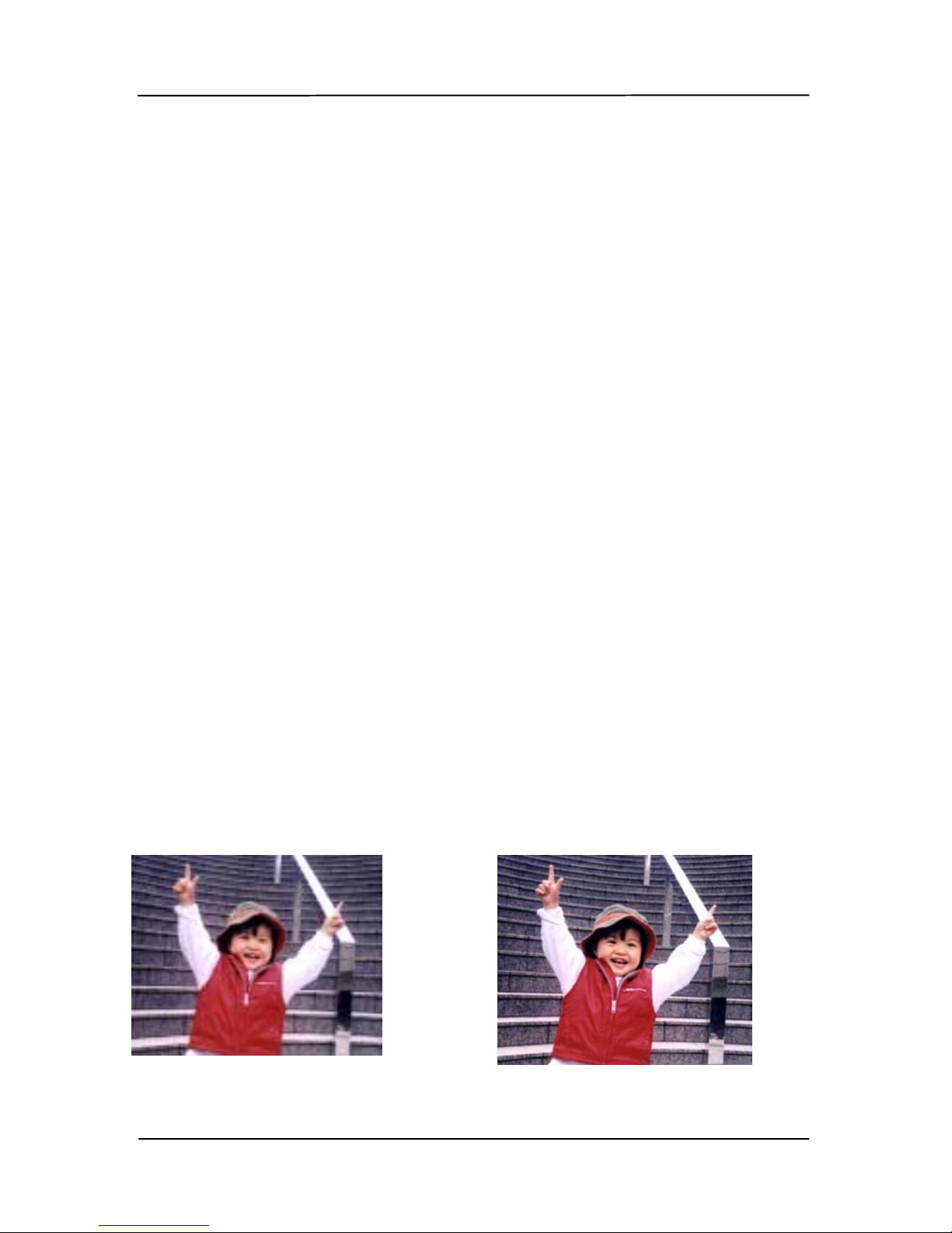
Resolution
A good control of the resolution results a
good detail of an image that scans. The
resolution is measured by dots per inch
(dpi). Normally, the greater the dpi
number, the higher the resolution and the
image file size. Be aware that greater
resolution takes more time to scan, and
more disk space for the scanning image.
For your information, an A4 size color image
scanned at 300 dpi at T r ue Color mode
consumes approximately 25 MB of disk
space. A higher resolution (usually means
over 600 dpi) is only recommended when
you need t o scan a small area at True Color
mode.
Choose a resolution value from the drop
down list. The default value is 200 dpi.
Available resolutions are 75, 100, 150,
200,300, 400 and 600. Or you may choose
your desired value by clicking the box in the
right side of the drop down list and press the
arrow key to select your desired value and
then click the Add button to include it in the
drop down list . Note: The resolution is up
to 300 dpi if an imprinter or a MICR reader
is installed or connected to the scanner.
Resolution: 75 dpi
Resolution: 150 dpi
Page 64
User’s Manual
5-16
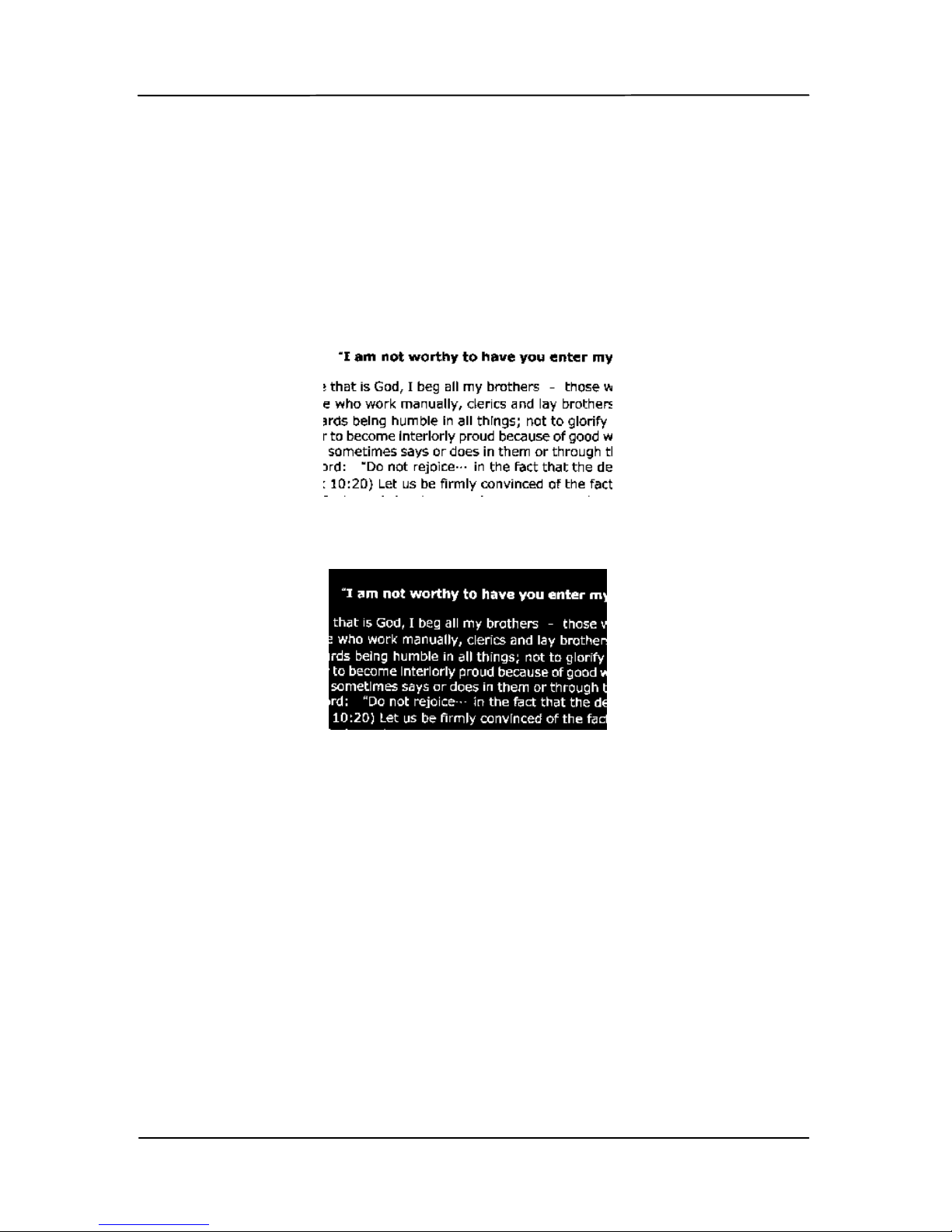
Invert Reverses the brightness and th e colors i n the
image. The default setting is Black on a White
background. Reverse mode is White on a Black
background. For color images, each pixel will be
changed into its complementary color at the
comma nd of Invert.
Black on White
White on Black
Page 65

User’s Manual
5-17
Scan
Source
Choice:
Auto Document Feed er: Used to scan
multiple pages.
Flatbed: Use d to scan a single page. For
example, pages fr om newspaper cli pping,
paper with wrinkles or curls.
Flatbed (book): Used to scan several
inside pages from book.
Automatic: Allow the scanner
automatically set its scan source. If
Automatic is sel ec ted and there is
document in both the auto document f eeder
(ADF) and the flatbed, then the scan source
will be automatically set to ADF. If
Automatic is sel ec ted and there is
document only in flatbed, then the scan
source will be set to flatbed.
Merge Two Sides i n to One Im a g e:
If you have a sheet-fed duplex scanner with
front input tray, you can scan an A3 size
document with an innovative method.
Thus, fold your A3 size document into A4,
and then load the paper in the front tray.
Choose Merge Two Sides from the Scan
Source option and then the scanner is able
to scan both sides of your document and
merge two A4 images into one A3 image.
When you select Merge Two Sides into One
Image, the Cropping or Mult i-feed function
will be disabled.
Note the options vary b a sed on t y p e of
scanner.
Page 66
User’s Manual
5-18
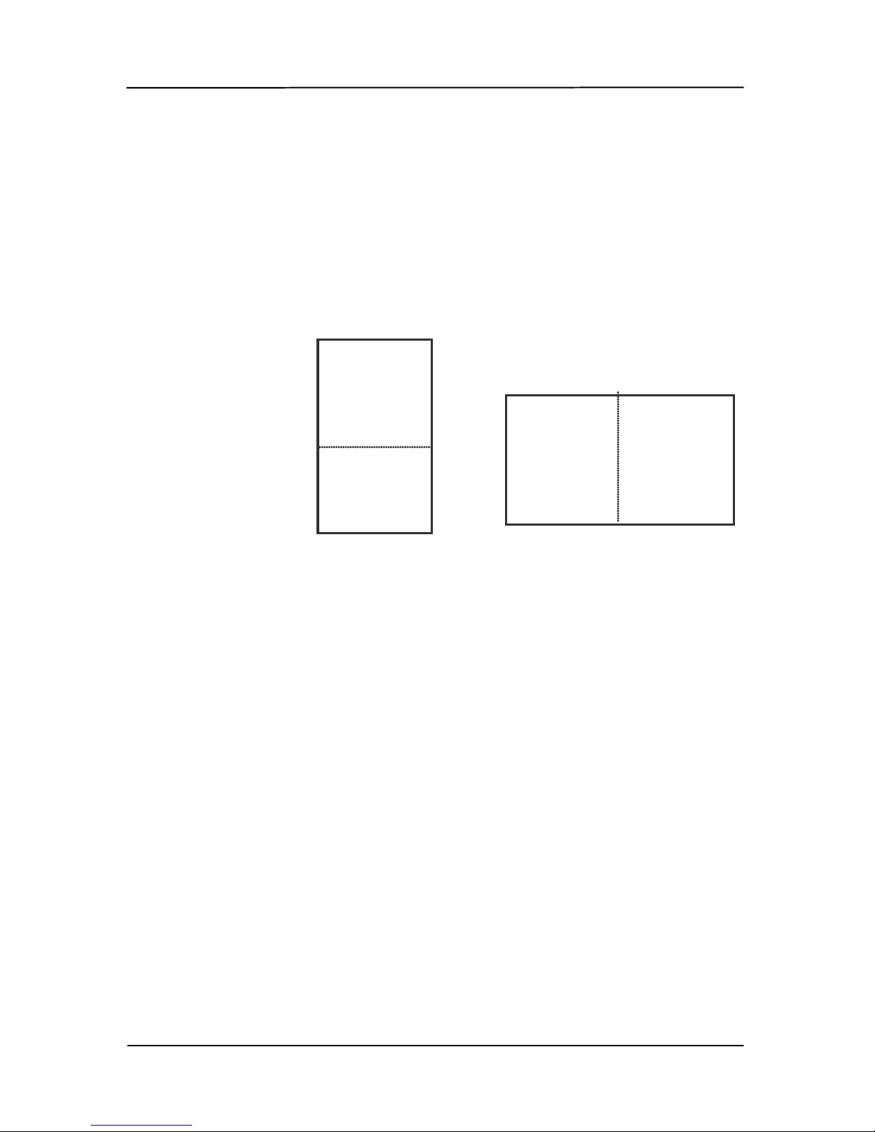
Select the “Merge Vertically” option to merge
the front side and the rear side of a page in to
one image vertically. If the “Merge Vertically”
option has not been selected, the front side
and the rear side of a page will be merged into
one page horizontally.
Note the options vary b a sed on t y p e of
scanner.
Front
Side
Rear
Side
Merge Vertically
Front
Side
Rear
Side
Merge Horizontally
Page 67
User’s Manual
5-19
Color
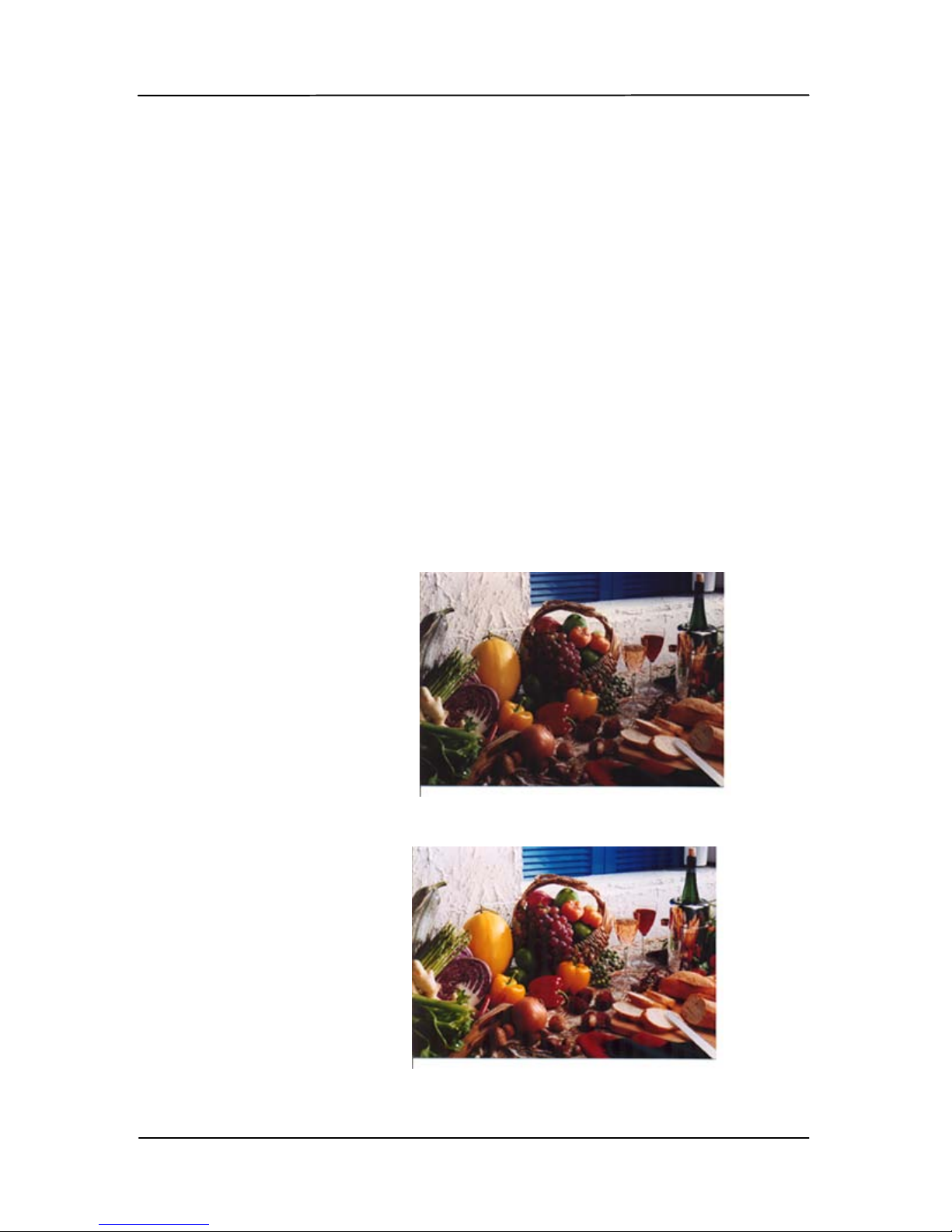
Matching
A.
The purpose of Color Matching is getting
the accurate color. This option uses the
default parameters (ICC profile) to adjust
the colors of the image.
Choice: None, Document, Photo
• None: Choos e “None” to disable this
option.
• Document: Choose “Document” if your
original contains pure text or a mixture
of text and graphic since it is an optimal
setting for regular business document.
• Photo: Ch oose “Ph oto” if your original
contains ph oto to reproduce your photo
in vivid color i mage.
Normal
After Color Matching
Page 68

User’s Manual
5-20
5.2.3 Scanning color images
The following options are available for scanning color images.
Brightness
Contrast
Resolution
Invert
5.2.4 Scanning grayscale images
The following options are available for scanning gray images.
Brightness
Contrast
Resolution
Invert
5.2.5 Scanning B&W images
The following options are available for scanning B&W images.
Binarization (Dynamic Threshold)
Resolution
Invert
Or
Binarization (Fix Processing)
Threshold
Brightness
Resolution
Invert
Page 69
User’s Manual
5-21
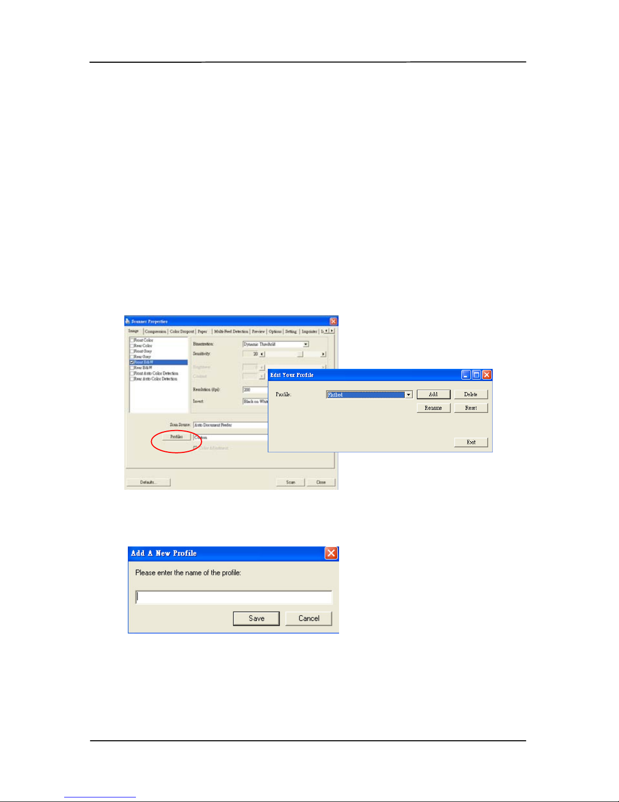
5.2.6 Editing profiles
The Scanner Properties dialog box allows you to change and
save your frequently used scan settings into a profile. You can
edit these profiles by renaming or deleting them.
To add a new profile,
1. Customize your settings. (For example, change your
resolution, image type, cropping method, scan size, or
other scan settings.)
2. Click the Image tab and then choose “Profiles” to prompt
the “Edit Your Profile” dialog box.
3. Click “Add” to enter the name of the profile and then
choose “Save”.
4. The new profile will be saved and shown in the “Profiles”
dropdown list box.
Page 70
User’s Manual
5-22
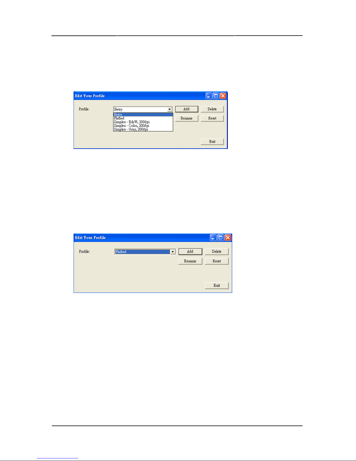
To load a profile,
1. F rom the Image t a b d ialog box, choose y our fa vorable
profile from the “Profiles” dropdown list box.
2. Your favorab le profile will be immediately loaded and
displayed on S canner Propert ies dial og box.
To delete a profi le,
1. From the Image tab dialog box, click “Profiles” to prompt
the Edit Your Profile dialog box.
2. Choose the profile you want to delete from the dropdown
list box.
3. Click “Delete”. A Confirm message “Are you sure you
want to delete this profile?” is prompted.
4. Choose “Yes” t o delet e or “Cancel” to quit.
Page 71
User’s Manual
5-23
To rename a profil e,
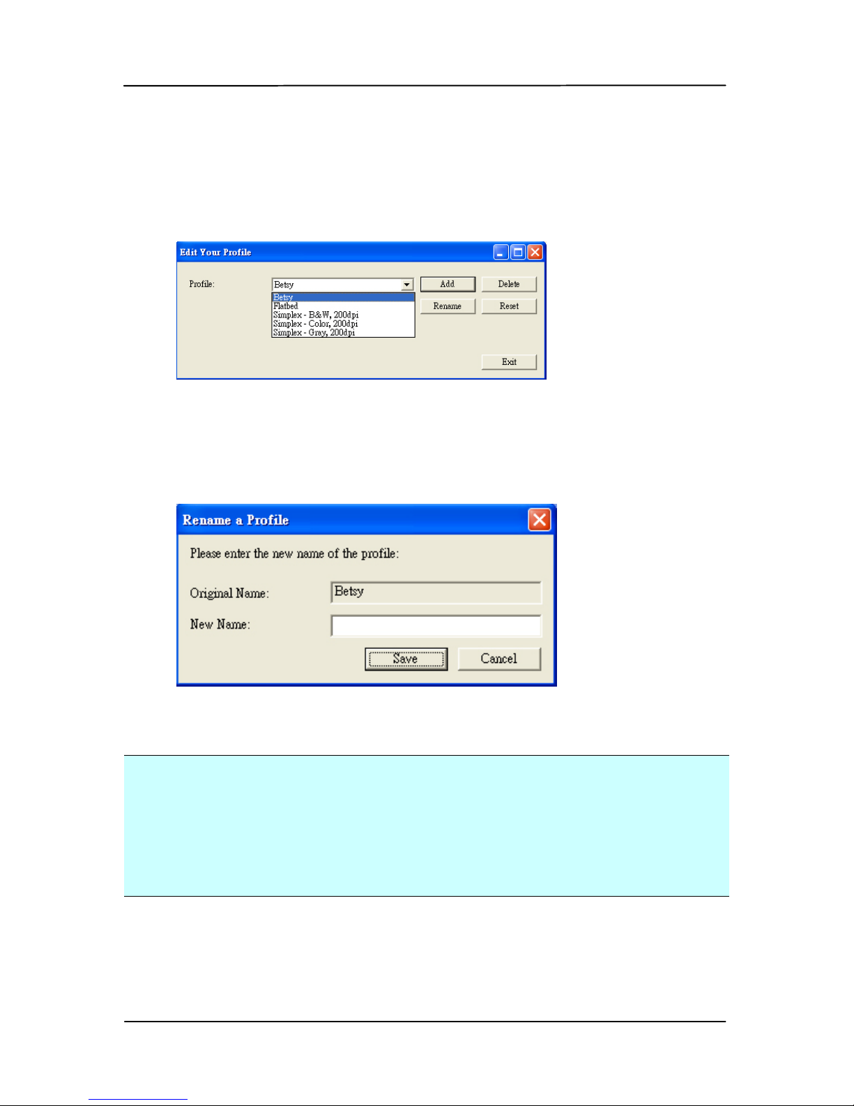
1. From the Image tab dialog box, click “Profiles” to prompt
the Edit Your Profile dialog box.
2. Choose the p rofile you want to rename fr om th e dropdown
list box and then click the Rename button.
3. E nter new name for the profile.
4. Choose “Save” to save the new profile or “Cancel” to quit.
Note:
The preset default profiles include Flatbed, Simplex-B&W, 200
dpi, Simplex-Gray, 200 dpi, Simplex-Color, 200 dpi, DuplexB&W, 200 dpi, Dupl ex -Gray, 200 dpi, Duplex-Color, 200 dpi.
If you have a simplex or a sheetfed scanner, the duplex or the
flatbed option will not be available.
Page 72

User’s Manual
5-24
5.3 The Compression tab
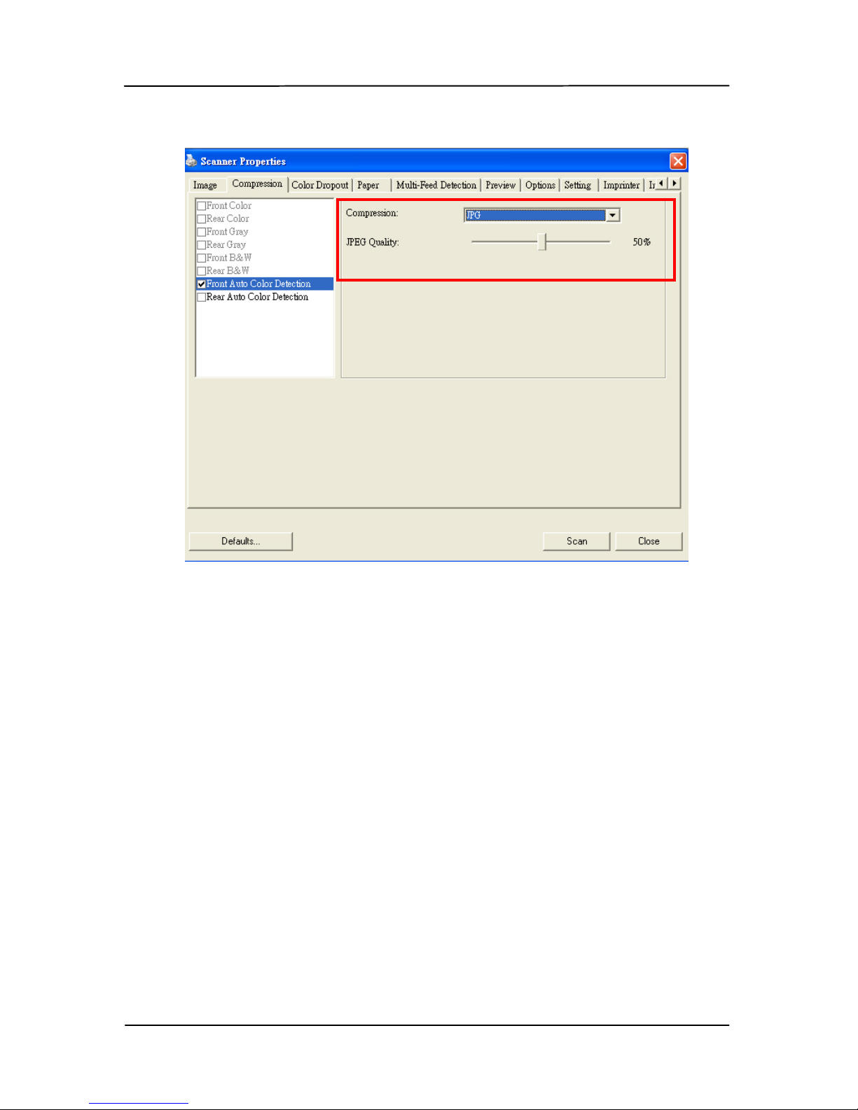
The Compression tab allows you to compress your scanned
image and choose the level of compression. Bi-tonal images
are normally compressed using CCITT standard called Group 4
(G4 ). Color a nd gra yscale images are often compressed using
JPEG technology. Move the JPEG Quality slider to the right or
left to incr ease or decrease the l evel of compression. Note the
greater the compression level, the lower image quality.
Default is 50%.
Note that the compression depends on y ou r image editing
application. If your image editing application does not support
the type of compression format, then either a warning
message will appear or the image quality of the compressed
file will not be acceptable.
JPEG ( Joi nt Photographic Editor Group): This group deve loped
and lent their name to a file compression standa rd for color
and grayscale images that is widely used by scanners, and
software applications. On Microsoft Windows-based systems, a
file with the extension .jpg has normally been compressed
using this standard.
For scanning color or gray images, the following compressions
are available:
None
JPEG
For scanning B&W images, the following compressions are
available:
None
G4
Page 73
User’s Manual
5-25
The Compression tab dialog box
Page 74

User’s Manual
5-26
5.4 The Color dropout Tab
5.4.1 Color dropout selection
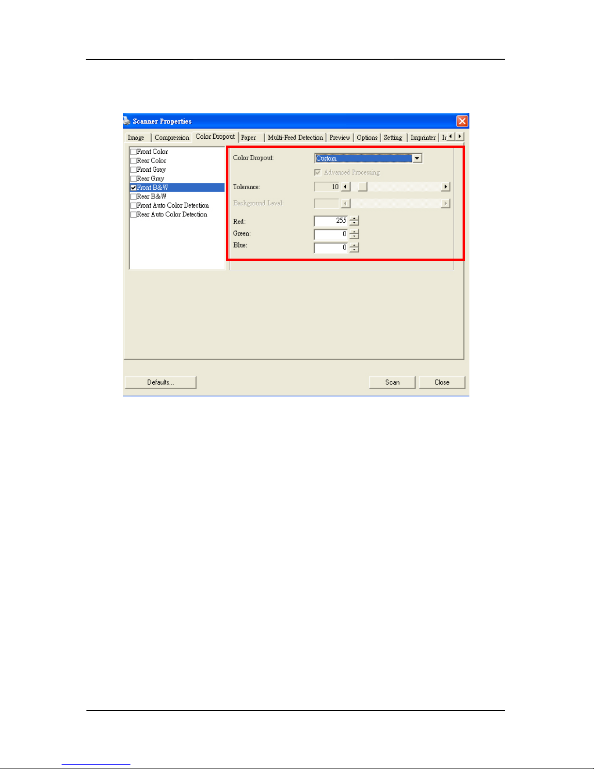
Color Dropout tab allows you to drop e ither of the r e d, b lue, or
green color in your scanned image. If your image contains red
color wa termark or b a ckground, choose the R (Red) channel
then any red watermark or background will be removed. This
feature is used to sharpen your text when using OCR (Optical
Character Recognition) software.
The “Custom” option allows you to sp ecify your des ired color to
be removed by entering its RGB (Red, Green, and Bl ue) value
respectively.
Tolerance: Specify th e allowable color range to be removed for
the color you selected. Specified range: 1 ~ 100
The large the numeric value, the wider the color dropout range
is.
Note that this function supports only black & white and gray
images. Therefore, be sure to choose any black & whi t e or
gray image type while applying this function.
Page 75
User’s Manual
5-27
The Color Dropou t d ialog box
Page 76
User’s Manual
5-28
5.4.2 Other color dropout options
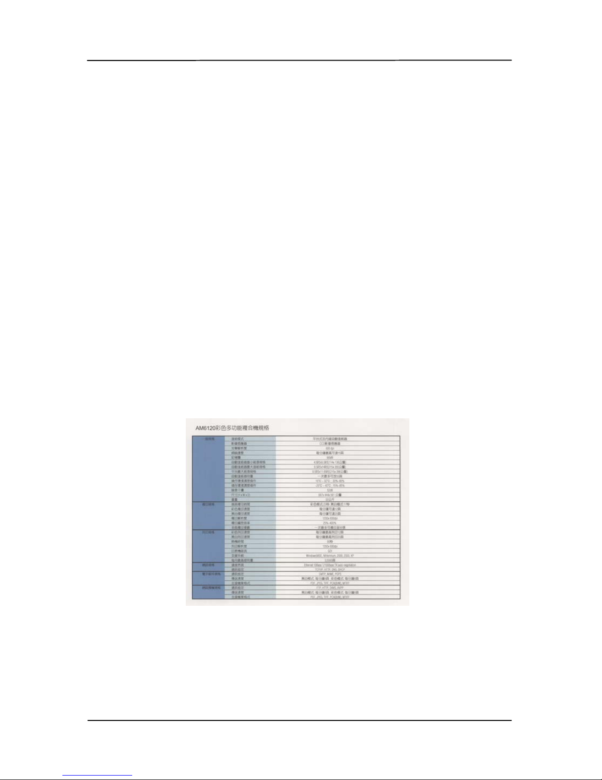
Advanced Processing provides two options that can adjust
your scanned image in the best optimal result.
Filter
Threshold
This value is used to determine the color
which will be dropped out. A lower value
will drop more of the selected color out,
while a higher value will leave more of the
selected color in.
Background
Level
The pixel which is higher than the
background value will be adjusted to the
lightest point. Adjust the value for both the
Filter Threshold and Background Level to
produce the best optimal result.
Example, sl i ghtly adjusting the background v alue makes
your text more cl ea r.
Original
Page 77
User’s Manual
5-29
Remove Blue, Threshold: 20, Background:
255
Remove Blue, Threshold: 20,
Background Level: 210
Page 78
User’s Manual
5-30
5.5 The Paper tab
The Paper tab allows you to define values relating to image
output (i.e., Auto Crop or not, Scan Area, OverScan, MultiFeed Detection).
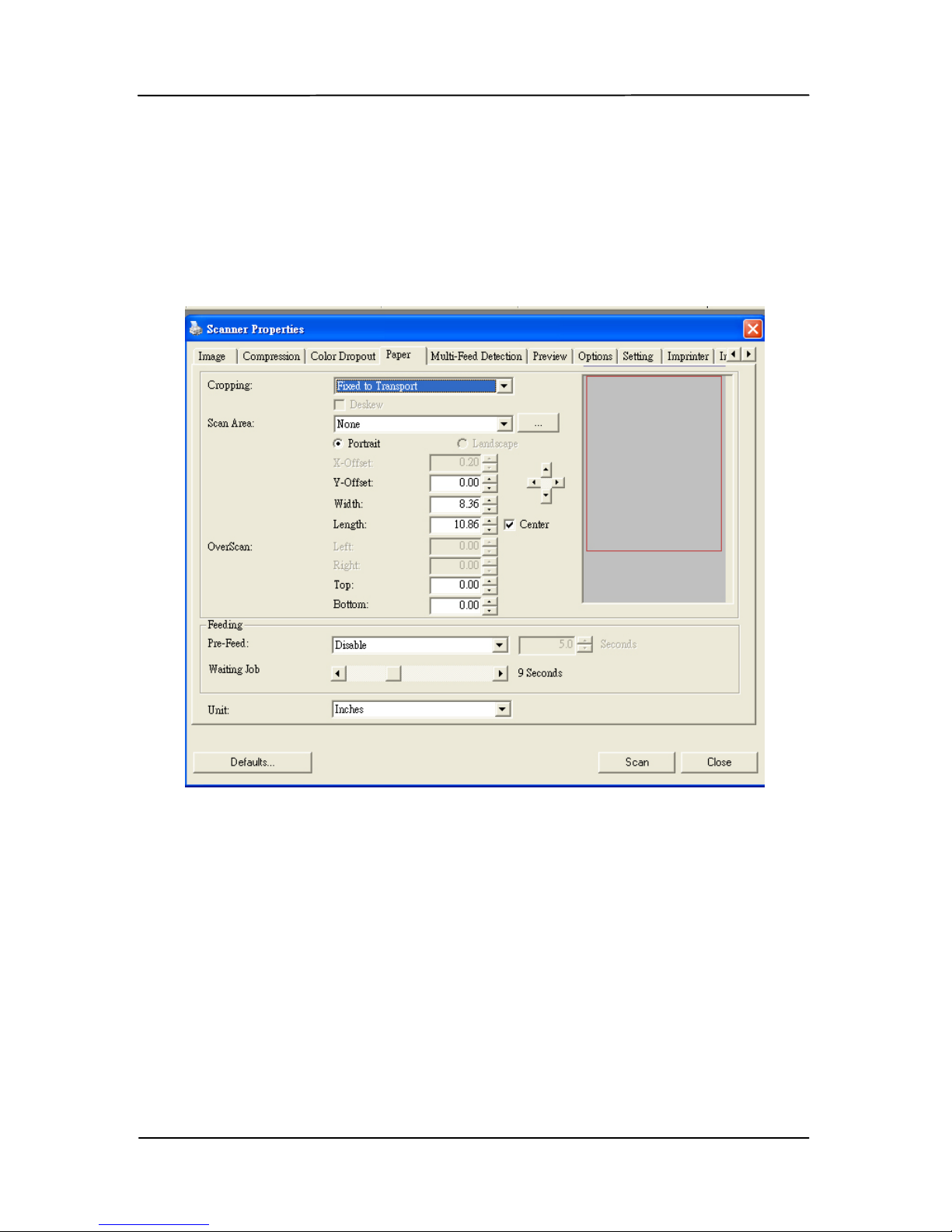
The Paper tab dialog box
Page 79

User’s Manual
5-31
5.5.1 Cropping
Cropping allows you to capture a portion of the document
being scanned. Choice: Automatic, Fixed to
Transport, EOP (End of Page) Detection.
Options Description
Automatic Automatic adjusts the cropping window
according to different document sizes. Use
this option for batches of mixed-sized
documents.
Fixed to
Transport
This feature allows you to define the area
or zone to be image d. Use for batche s of
same-sized documents. If you select this
option, you can use the arrow keys to
define the x and y offset values, width and
length to redefine your scanned area. The
Display window will show image placement
as you change the values.
EOP (End of
Page)
Detection
This feature allows you to define the area
or zone to be imaged. Us e f or batches of
same-width but different length
documents. If you select this option, you
can use the arrow keys to define the x and
y offset values, width and length to
redefine your scanned area. The Display
window will show image placement as you
change the values.
Page 80

User’s Manual
5-32
Automatic
Multiple
This option allows you to place various
sized docume nts such as photos, ID Cards,
or business cards on the flatbed (if
available) and lets you create multiple
individually cropped images in one scan .
Note: To correctly create multiple images,
please make sure there is at l east 12mm
(0.5”) of space between each document.
The following options are only available when Fixed to
Transport is selected.
X-Offset — the distance from the left end of the
scanner to the lef t edge of the scanning area.
Y-Offset — the position from the top end of the
document to the top end of the scanning area.
Width — the width of the scanning area.
Length — the length of the scanning area.
Center: automatically calculates the x-offset for center-
fed feeding based upon document size sel ected.
— relocate the scan area by click the arrow key on
the cross sign while retain the scan size. View the result
from the Display window.
Page 81
User’s Manual
5-33
5.5.2 Other Paper Selection
Deskew
Use this option to automatically deskew a document.
Scan Area
Choose your desired paper size with the drop-down list box.
Or you may select a custom paper size by clicking the Scan
Area box and then cli ck Add to include in the choice.
Choice: None, US Letter- 8.5”x 11”, US Legal – 8.5” x 14”,
ISO A4 – 21 x 29.7 cm, ISO A5 – 14.8 x 21 cm, ISO A6 – 10.5
x 14.8cm, ISO A7 – 7.4 x 10/5 cm, ISO B5 – 17.6 x 25 cm,
ISO B6 – 12.5 x 17.6 cm, ISO B7 – 8.8 x 12.5 cm, JIS B5 –
18.2 x 25.7 cm, JIS B6 – 12.8 x 18.2 cm, JIS B7 – 9.1 x 12.8
cm, Scanner Maximum, Long Page.
Long Page:
When you need to scan documents whose length exceeds
scanner maximum, please choose Lon g P a g e. Note if Long
Page is selected, the Multi-Feed Detection will not be available.
Options: Unknown Length, Enter Length (Note: This option
varies due to type of scanner.)
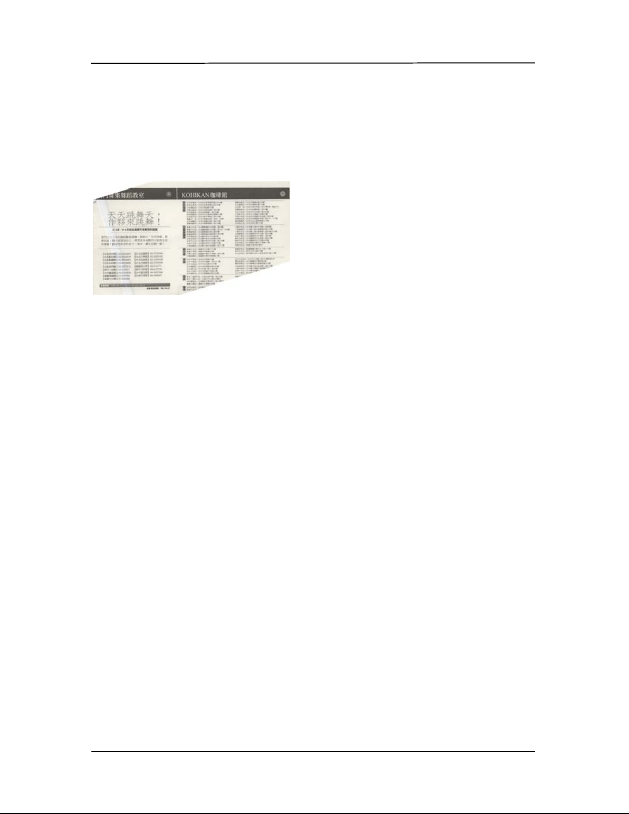
Note: If the skew angle
is too great, som e of the
image may be c ut off.
Page 82

User’s Manual
5-34
Choose “ Unknown Length” if you have a batch of long page
document with unknown length. Choose “Enter Length” to
enter the length and width of your documents or your desired
scan size on documents. This is useful when you have a batch
of documents with the same scan size or a batch of samesized documents.
OverScan
Overscan allows you to add a specific margin at top and
bottom or right and left (Options vary based on the type of
scanner) of the edge of the image. This is used to reduce
possible corner cli pping on the skewed images and often
applied to a batc h of skewed document to be scanned in the
auto document feeder. Select a valu e bet ween 0 and +5 mm.
Note the overscan result will not be shown in the Display
window and that the availability of the function varies based
on type of scanner.
Pre-Feed
Choice: Enable, Disable. If enable is selected, you can set the
amount of time the scanner starts pre-feeding your paper af ter
your documents has been loaded int o th e feeder. The defau lt
is disable.
Transport Timeout
Set the amount of time the scanner will wait and then start
auto scan after the first scan job is completed. If you have
many separate documents need to be scanned at t he same
scan settings, this feature is especially useful. The default is 0.
The value ranges from 0 to 30 seconds.
Page 83

User’s Manual
5-35
Note:
1 Within the specified timeout period, if you load your
document to the feeder, the scanner starts scanning
automatically.
2 If your scanner has a flatbed option and you place your
paper on the flatbed, after the timeout period, you need
to click the Scan button on the TWAIN user interface to
start scanning.
Page 84
User’s Manual
5-36
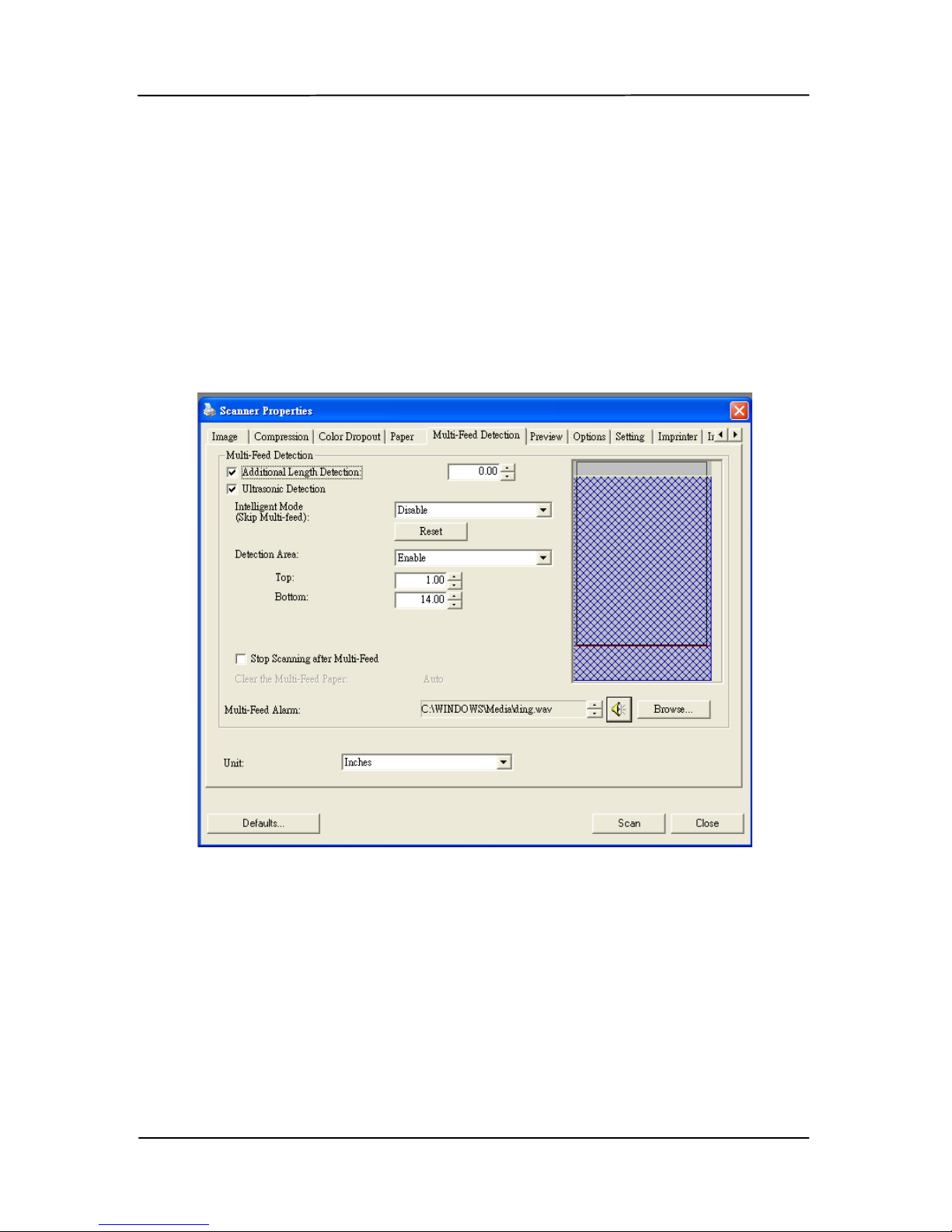
5.6 The Multi-Feed Detection tab
Multi-Feed Detection
Multi-Feed Detection allows you to detect overlapped
document that go through the auto document feeder. MultiFeed usually occurs due to stapled documents, adhesives on
documents, or electro-statically charged document. Note: The
availability of the function varies based on type of scanner.
Page 85

User’s Manual
5-37
Additional Length Detection
Additional Length Detection allows you to define the length of
document being multi-fed. This value indicates the additional
length exceeding your scan area. The Display window will
show the size of the document as you change the value. A
value of 0 indicates no additional length detecti on. The
Additional Length Detection is best used when scanning samesize documents in the auto document feeder.
Intelligent Mode (Skip Multi-Feed) By Ultrasonic
Detection
Some documents which are glued with a photo or a label may
easily be detected as multi-feed yet you wish to bypass these
multi-feed conditions. In this case, you can use the intelligent
mode to let the scanner memorizes and skips these multi-feed
conditions. Choice includes Disable, By Length, By
Position, By Length+Position. Note: The availability of
this feature varies b ased on type of scanner.
By Length: When a multi-feed is detected for the first time,
the scanner memorizes the length of the paper attached to the
document. When you perform next scanning, this pattern of
multi-feed will be by pas s e d.
By Position: When a multi-feed is detected for the first time,
the scanner memorizes the position of the paper attached to
the document. When you perform next scanning, this pattern
of multi-feed will be bypassed.
Page 86

User’s Manual
5-38
By Length+Position: When a multi-feed is detected for the
first time, the scanner memorizes the length and position of
the paper attached to the document. When you perform next
scanning, this pattern of multi-feed will be bypassed.
To use the intelligent mode,
1. Choose your desired multi-feed detecting method to
bypass by.
2. When multi-feed occurs during scanning, a multi-feed
message appears .
3. Press t h e Scan button on the scanner. The LED indicator
first turns to red color and then stays in green color.
4. Click OK to close the multi-feed message.
5. Open your TWAIN data source in your scanning
application. The same multi-feed condition will not be
recognized as multi-feed.
Note:
1. You can clear the previous multi-feed conditions by
clicking the Reset button.
2. The scanner can memorize to bypass up to 25 multi-feed
conditions.
3. If you uninstall your scanner driver, the previous multi-
feed conditions which have been set to memorize and skip
will still be valid.
Page 87
User’s Manual
5-39
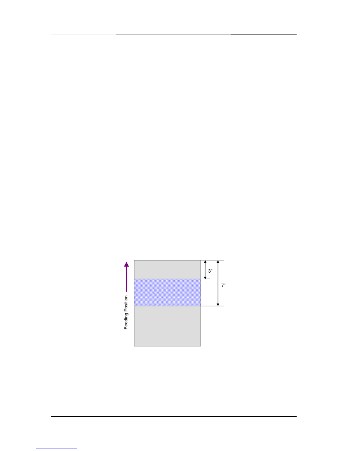
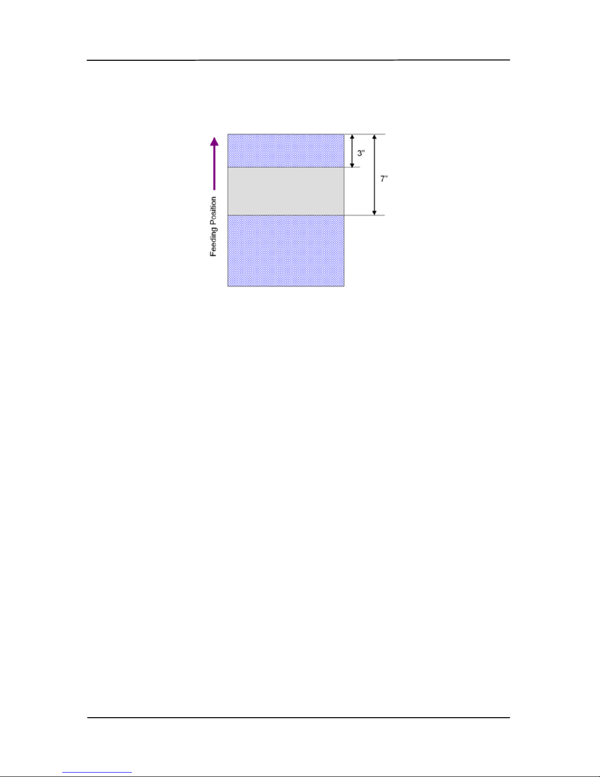
Detection Area
This option allows you to specify a multi-feed detection area.
To specify a multi-feed detection area,
1. Choose Disable from the Intelligent Mode. The Detection
Area will be enabled.
2. Choose Inside the Range or Outside the Range. The
detection area will be highlighted.
3. Drag your mou se poi nter on t he top or the bottom of the
detection area to specify your area in the display window.
Or you may use the up and down arrow key of the Top
and Bottom to change its size. The Top indicates the
starting position of the detection range. The Bottom
indicates the ending position of the detection range. Note
the top value and the detection range has to be at least 1
inch.
Detection Area: Insi de t he Range, Box, Top: 3”, Bottom: 7”
Page 88
User’s Manual
5-40
Detection Area: Outside the Range, Box, Top: 3”, Bottom: 7”
Page 89
User’s Manual
5-41
Ultrasonic Detect i on
Ultrasonic Detection allows you to set overlapped document
by detecting paper thi c kness between documents. Note
:
The availability of the function varies based on type of
scanner.
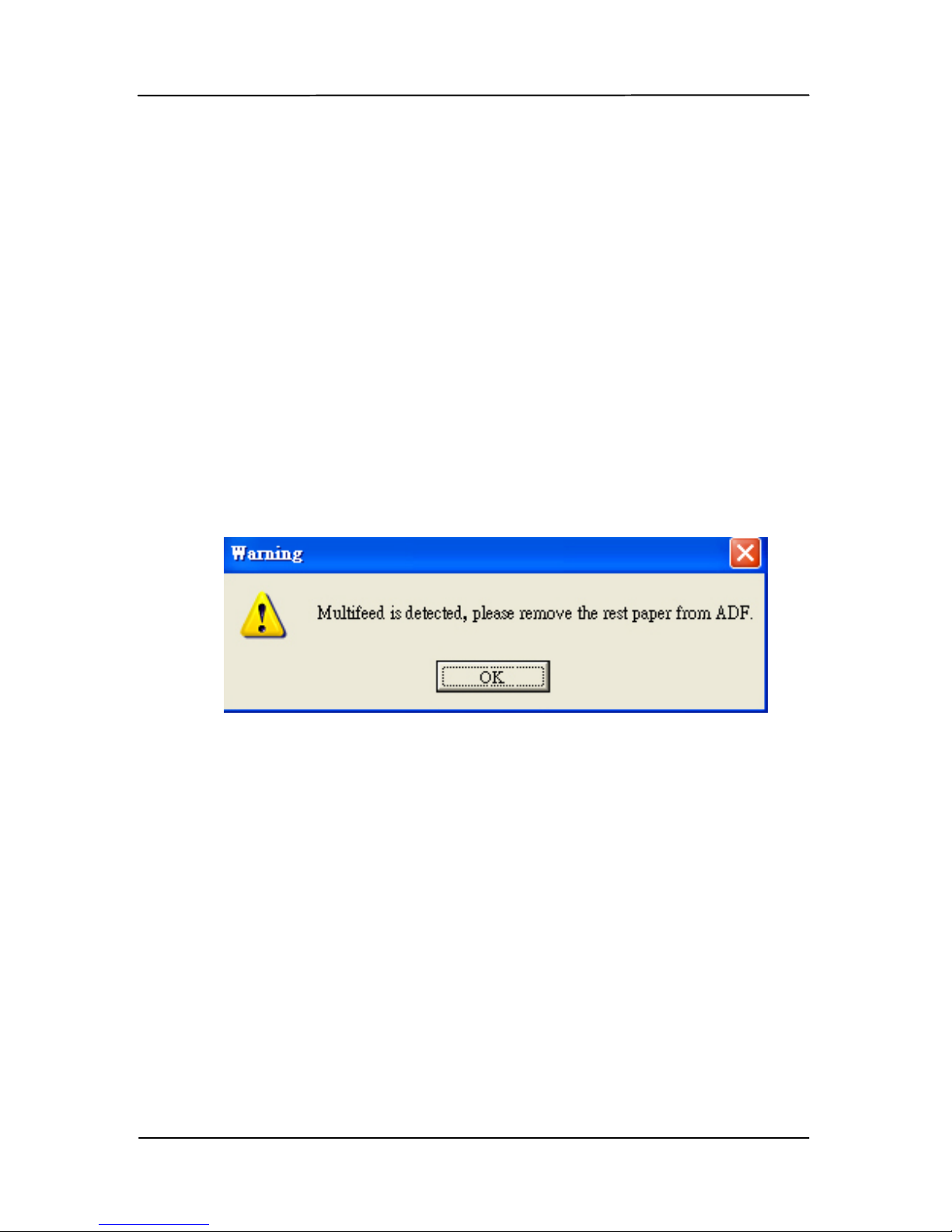
There are two options available if Multi-Feed is detected.
Stop Scanning after Multi-Feed
If this is selected, the scanner will stop the feeder and
display the following Warning dialog box if multi-feed is
detected.
Action:
1. Follow the instruction on the Warning dialog box to
remove the rest pages on the feeder.
2. Click OK to close the Warning dialog box.
3. Scan the rest pages.
Page 90

User’s Manual
5-42
Multi-Feed alarm
If a wave file is added, the scanner will make a sound
alarm if multi-feed is detected yet no Warning dialog box
will be displayed.
If “Stop Scanning after Multi-Feed” is selected, the
scanner will stop the feeder.
If “Stop Scanning after Multi-Feed” has not been selected,
the scanner will continue to scan till the end of your
document.
Action:
1. If “Stop Scanning after Multi-Feed” is selected, follow
the action described in the preceding section “Stop
Scanning after Multi-Feed” on t he pr e vious page to
complete your job .
2. If “Stop Scanning after Multi-Feed” has not been
selected, rescan the pages where mul ti-feed is
detected.
How to add the sound alarm
:
1. Click the Browse button on the right side of the speaker
icon. The O pen dialog box appears.
2. Choose your wave file.
3. Click the Open button. The wave file is added.
Units
Defines the prim ary measu rement system. Inches,
Millimeters, and Pixels ar e av ailable.
Page 91
User’s Manual
5-43
5.6.1 Relative to document
Relative to document: (used for batches of same-sized
documents)
This option allows you to crop different areas on your
documents and deliver these images in B&W, Gray, or Color
separately. For example, there are applications which require
you to store the entire document in B&W and a part of the
document in color to save storage space. This is useful for
documents where a photograph or signature appears in a
consistent area on the document such as resumes, and so on.
The following procedure describes how to reproduce the entire
document in B&W and a portion of document (picture) in color.
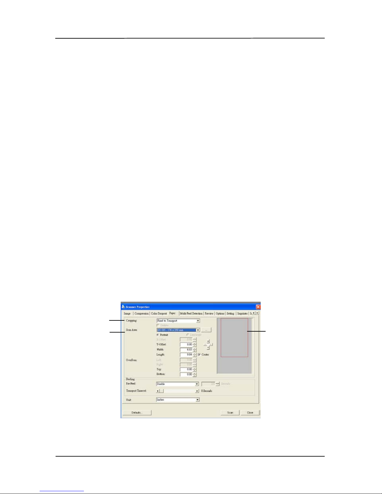
1. On t he Paper tab, choos e “Relative to Document” or
“Fixed to Transport” from th e Cropping option.
2. Choose y our scan size from the S can A rea option. The
selected scan size will be displayed in a red rectangular
box. This is also the scan size of your entire document.
(For example, ISO B5. If you have not chosen a scan
area and leave the selecti on as None, then the default
area will be the scanner’s maximum.)
1
2
A red
rectangular
box
Page 92
User’s Manual
5-44
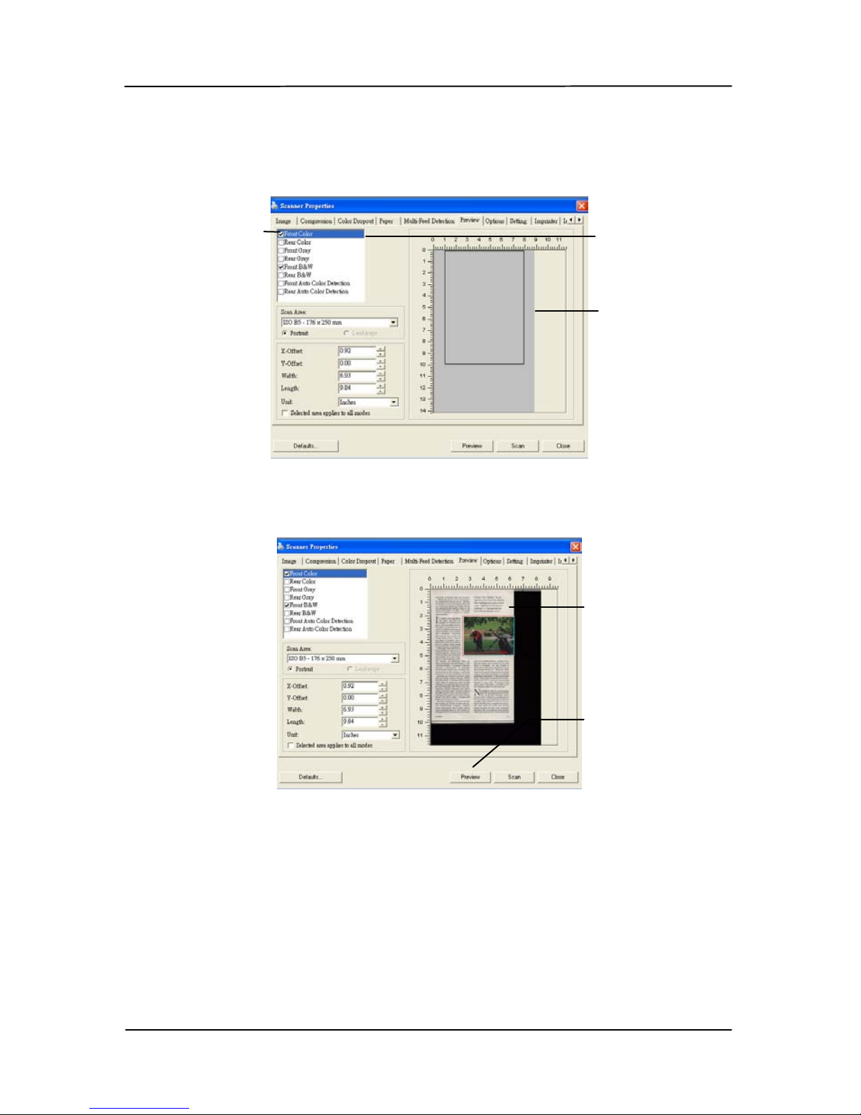
3. Click the Preview tab to display the Preview window. A
black rectangular box appears to indicate the max. scan
size your have just selected.
4. Click the Preview button to view the entire image in low
resolution to correctly crop your relative scan area.
5. Select image type from the I m age Selec tion box. The
selected image will appear in highlighted color. ( For
example, F ront C olor)
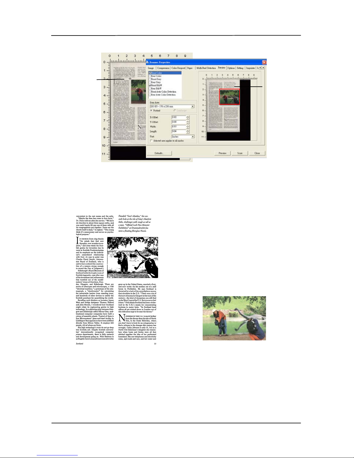
6. Place your cursor on the Preview window and click your
left mouse button. A cross sign will appear as illustrated.
Create your relative scan size diagonally by dragging the
left mouse button to y our preferable size. The selected
area will appear in a red box as illustrated.
A black
rectangular
box
The selected
image
The Preview
Image
The Preview
Button
The Image
Selection
Box
Page 93
User’s Manual
5-45
7. Check the B&W image from the Image Selection box to
scan the entire document.
8. Click the Scan button to start scanning the document in
two image types and sizes. (See the result in below.)
The entire document in B&W The relative area in color
The
Relative
Area
A Cross
Sign
Page 94
User’s Manual
5-46
5.7 The Preview tab
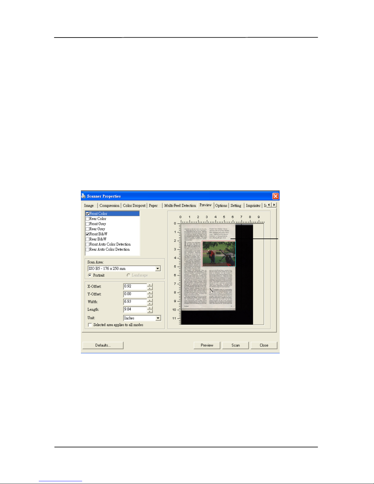
The Preview tab allows you to preview (a low-resolution scan)
your image before final scan. This preview image lets you
allocate y our scan area. Y ou c an choose your scan area by the
“Scan Are a ” d rop down lis t box or placing your cursor on the
Display window and dragging i t diagonally on the Display
window. Then, a red rectangle box will appear to indicate the
selected area.
Note: If you choose “Automatic Cropping” on the “Paper Tab”,
then to select a scan ar e a on t he Preview tab is not allowed.
The Preview Tab
The Display
Window
Page 95
User’s Manual
5-47
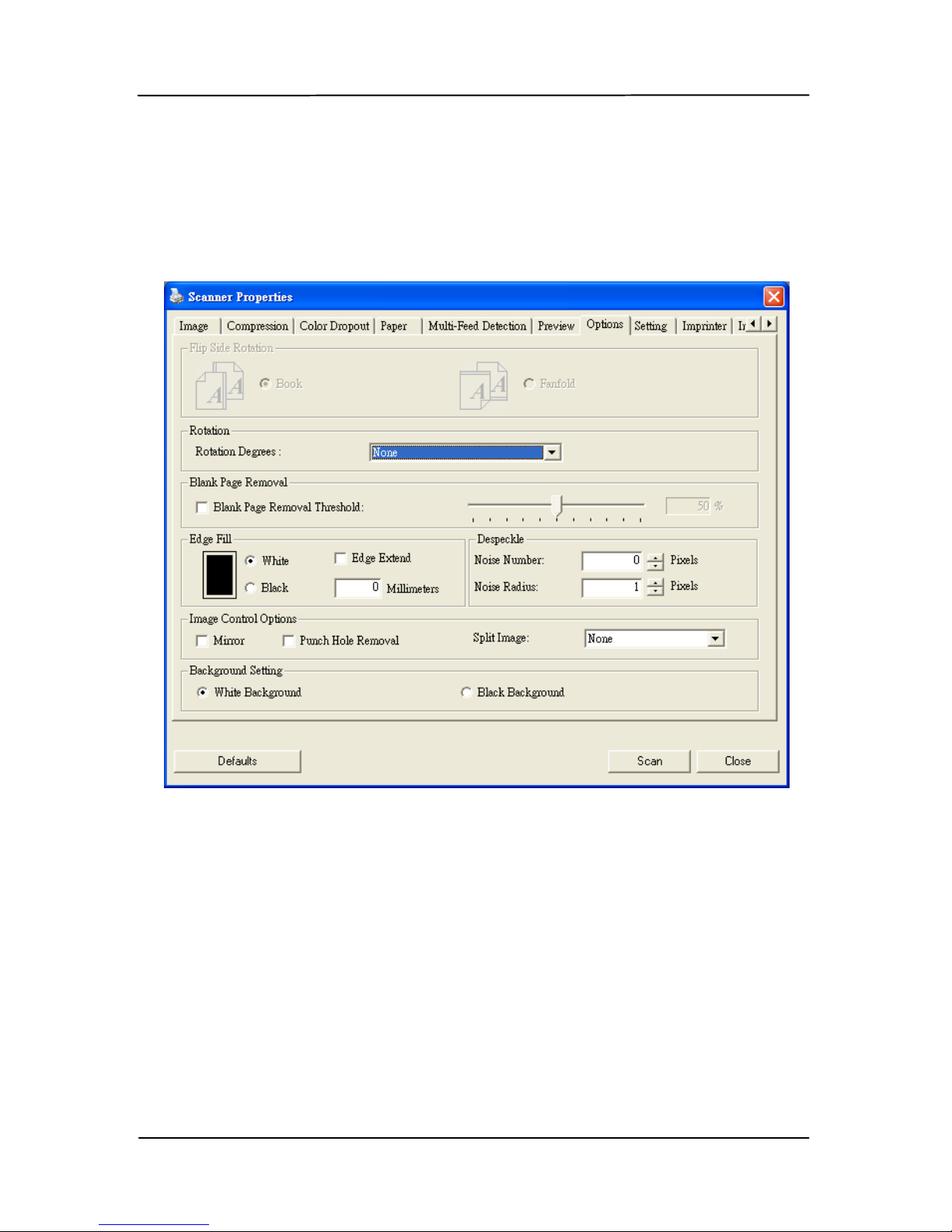
5.8 The Options tab
The Options tab allows you to set following additional image
processing settings.
The Option tab dialog box
Page 96
User’s Manual
5-48
Flip Side
Rotation
Select “fanfold” to rotate the image
of the reverse side to 180 degrees.
This is applied to double-sided
document which are viewed in
portrait are sometime fed into the
scanner in landscape or vice versa.
Choice: Book, Fanfold.
If “Book” is selected, the image of
the reverse side will not be rotated.
The following illustration shows the documents which should
be viewed in portrait are fed into the scanner in landscape
Page 97
User’s Manual
5-49
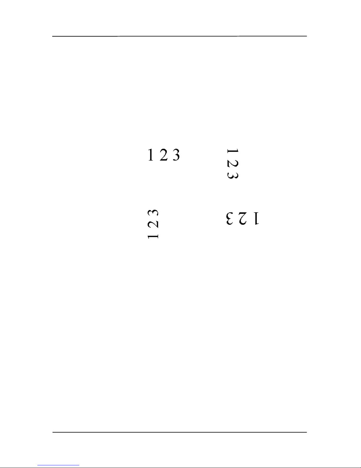
Rotate Image Choose the rotation angle from the
drop down list if you wish to rotate
your scanned image.
Choice: None, 90°CW(cl ockw i se),
90°CCW(counter clockw ise), 180°,
Auto based on contents, Auto
rotate every ev en p a g e.
Original
Rotate 90°CW
Rotate 90°CCW
Rotate 180°
Auto based on contents: When
Auto based on contents is selected,
images can be rotated to their proper
orientations based on their contents.
Auto rotate every ev en page:
Automatically rotate 180° on every
even page. This is especially useful
when you scan the inside pages from a
book. As a result, if you choose
“Flatbed (book)” fr om th e “Scan
Source” option, “auto rotate every even
page” will be selected as default.
Note: Option varies based on type
of scanner.
Page 98
User’s Manual
5-50
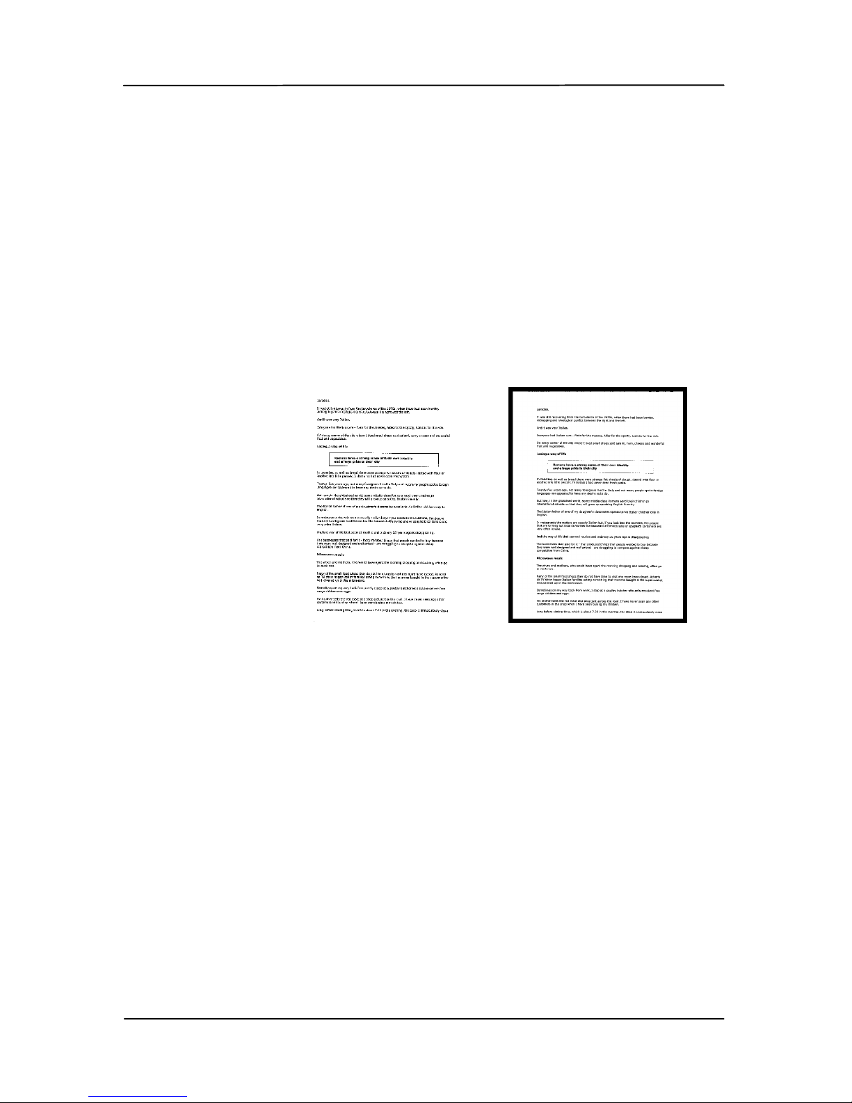
Blank Page
Removal
Check if you wish to remove the blank page
and move the slider to the left or right to your
desired threshold.
Edge Fill
Check White or Black if you wish to add white
or bla ck edge on the bor d er of your scanned
image. Enter the value from 0 to 5 mm.
Default value is 0.
Original
Edge Fill: 5mm (Black)
Page 99

User’s Manual
5-51
Image
Control
Option
Check the Mirror box if y ou wis h to reverse t he right
and left side of your image.
Original
The Mirror Effect
Page 100
User’s Manual
5-52
Punch
Hole
Removal
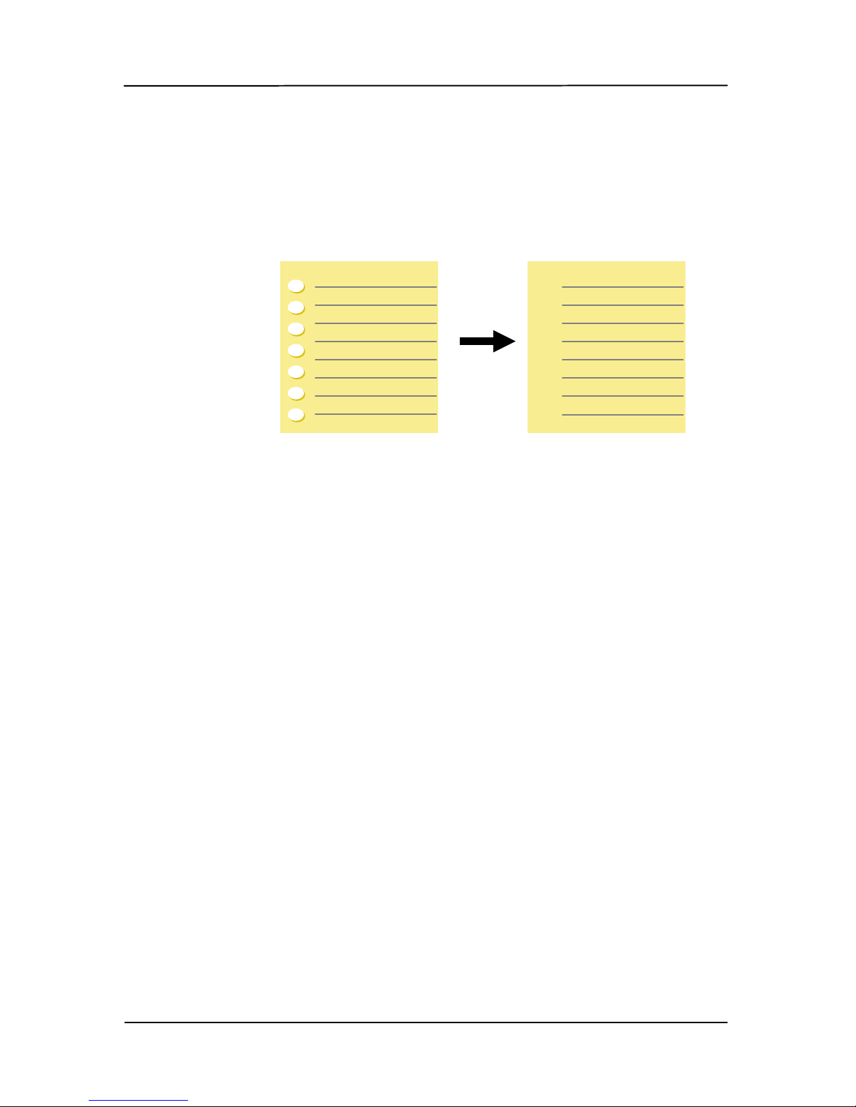
You can remove punch holes from the output
scanned image when scanning punched
document. Note the availability of this feature
varies depending on your scanner model.
Punch holes cannot be removed w hen:
• Resolution is set lower than 150dpi
• The hole is near the edge of the documen t
• The holes are not aligned along the edge of the
document
• Punch Hole Removal is available only when
“Auto Crop” is enabled. If either “Fixed to
Transpor t”, “EOP (End of Page) Detection”,
“Automatic Multiple”, “Relative to Documents”
is selected from the Cropping option on the
Paper tab, the Punch Hole Removal option will
be disabled.
Original
Output image
 Loading...