

Page 1
[Type here]
Model: AV-1364
HD-SDI Auto-Tracking Camera
User Manual
V1.1
(English)
Please read this User Manual
throughout before using.
www.avipas.com
Page 2
[Type here]
Preface
Thank you for using this SDI Auto-tracking Camera.
This manual introduces the functions, installation process and operation of this camera. Prior to installation
and usage, please read the manual thoroughly.
Precautions
This product should only be used under the specified conditions in order to avoid any damage to the camera:
◼ Do not subject the camera to rain or moisture.
◼ Do not remove the cover. Otherwise, you may risk receiving an electric shock. In case of unintended
equipment operation, contact an authorized engineer.
◼ Never operate under unspecified temperature, humidity or power input.
◼ Please use soft dry cloth to clean the camera. If the camera is very dirty, clean it with diluted neuter
detergent; do not use any type of solvents, which may damage the surface.
Note:
This is a class A production. Electromagnetic radiation at certain frequencies may affect the image quality of
TV in home environment.
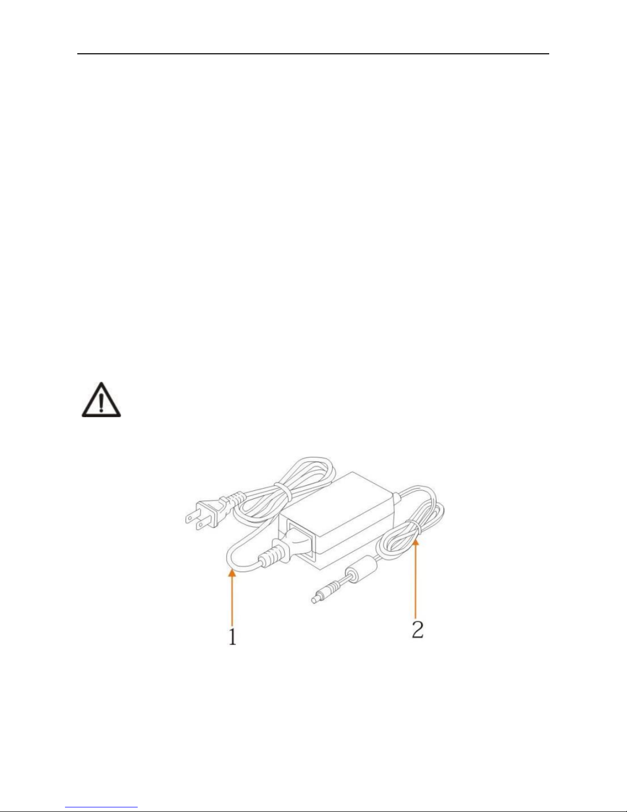
To extend the power cord of this camera, the user is supposed to connect extra length only from
terminal 1 (voltage 220V/110V), while terminal 2 (DC12V) should remain the original piece. Otherwise
abnormal functions of the equipment will be caused!
Page 3
[Type here]
Attentions
• Electric safety
Installation and operation must be in accord with electric safety standard.
• Caution to transport
Avoid stress, vibration or soakage during transport, storage and installation.
• Polarity of power supply
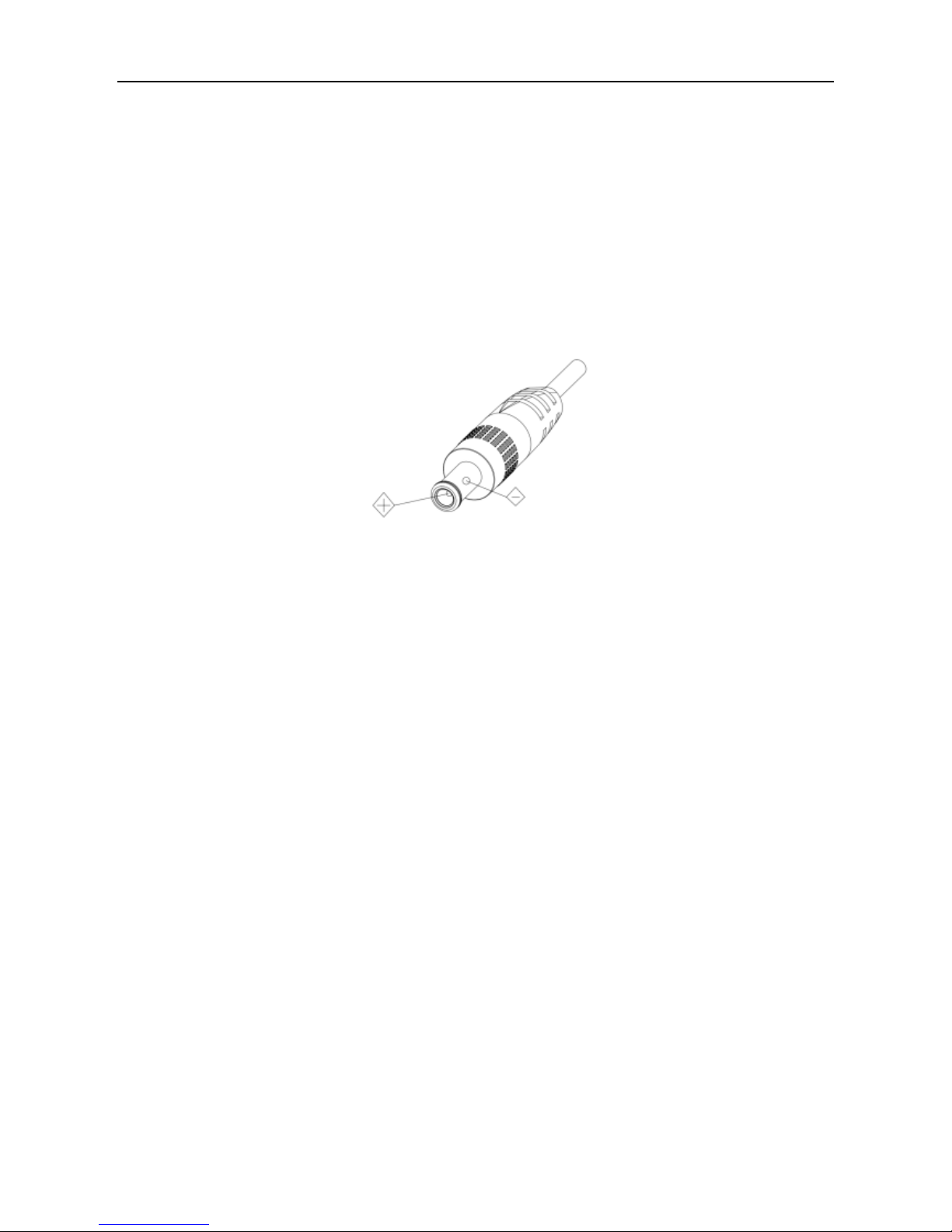
The power supply of the product is ±12V, the max electrical current is 2A. Polarity of the power supply plug is
shown in the drawing below.
• Careful of installation
Do not grasp the camera lens when carrying it. Don’t rotate camera lens by hand. Mechanical damage may result
from doing so.
This series product must be placed on a smooth platform or surface. It cannot be installed slantwise.
If the camera is used with TV or computer, the base can be fixed by four double-sided adhesive trays.
Don’t apply in corrosive liquid, gas or solid environment to avoid any cover (organic material) damage.
Make sure no obstacle is in the rotation range.
Never power on before installation is completed.
• Don’t disassemble discretionarily.
We are not responsible for any unauthorized modification or dismantling.
• Attention!
Specific frequencies of electromagnetic field may affect camera image!
Page 4

[Type here]
Contents
1. Fast Installation ......................................................................................................................................................... 1
1.1 Camera Interface Illustration .......................................................................................................................... 1
1.2 Power On ........................................................................................................................................................ 2
1.3 Video Output ................................................................................................................................................... 3
1.4 Bracket Mounting ......................................................................................... Error! Bookmark not defined.
2. Product Overview ..................................................................................................................................................... 5
2.1 Product Introduction ....................................................................................................................................... 5
2.2 Main Features ................................................................................................................................................. 5
2.3 Technical Specifications ................................................................................................................................. 6
2.4 Interface Instructions ...................................................................................................................................... 7
3. Application Instructions ............................................................................................................................................ 8
3.1 Video Output ................................................................................................. Error! Bookmark not defined.
3.2 Remote Control ............................................................................................................................................... 8
3.3 Menu Settings ............................................................................................................................................... 11
4. Network Connection ............................................................................................................................................... 18
4.1 Connecting Mode.......................................................................................................................................... 18
4.2 IE Log In ....................................................................................................................................................... 20
5. Serial Communication Control ............................................................................................................................... 33
5.1 VISCA Protocol List ..................................................................................................................................... 33
5.2,Pelco-D Protocol Command List .................................................................................................................. 38
5.3 Pelco-P Protocol Command List ................................................................................................................... 39
6. Camera Maintenance and Troubleshooting ............................................................................................................ 40
6.1 Camera Maintenance .................................................................................................................................... 40
6.2 Troubleshooting ............................................................................................................................................ 40
Page 5
1
1. Fast Installation
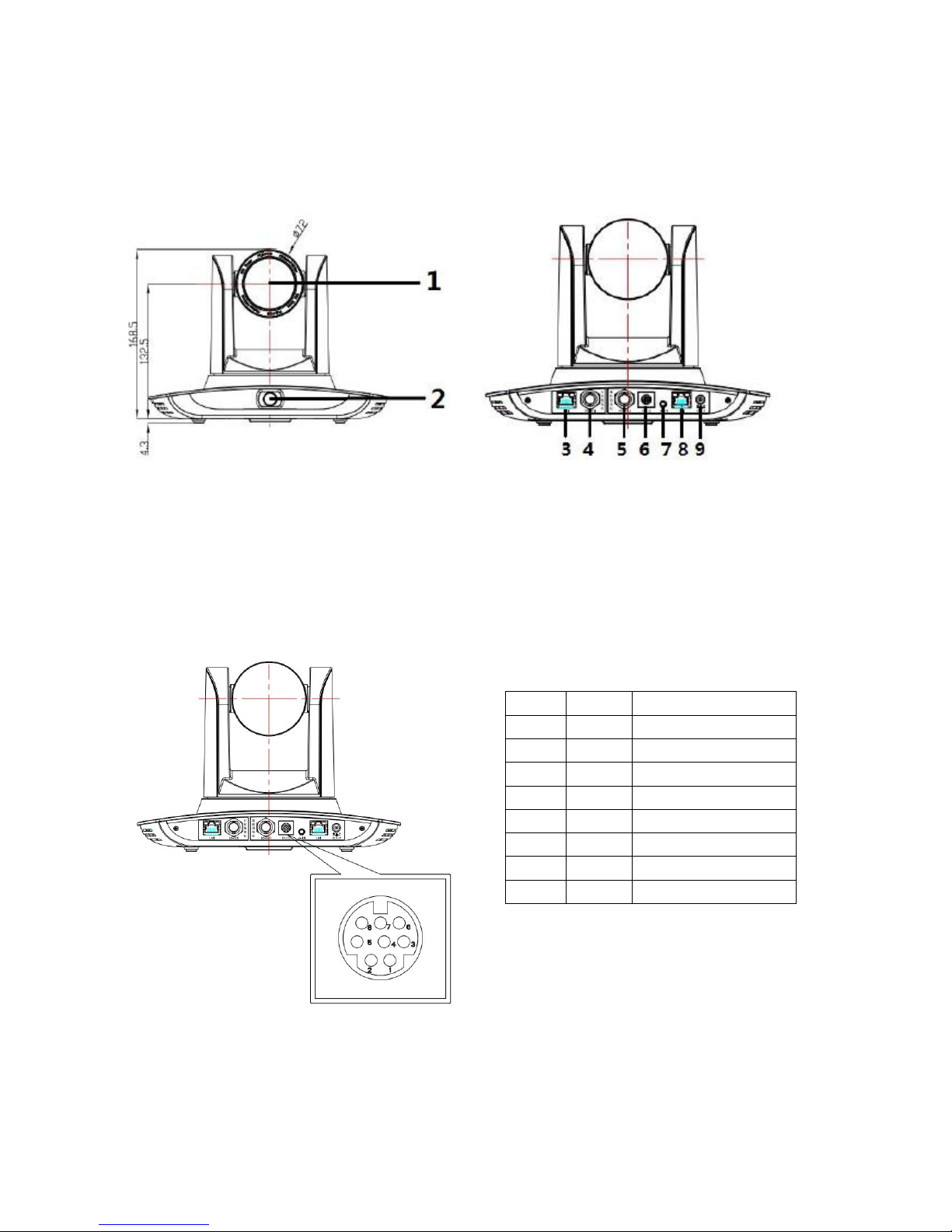
1.1 Camera Interface Illustration
Figure 1.1 AV-1364 Front View Figure 1.2 AV-1364 Rear View
1. Close-up lens
2. Panorama lens
3. LAN network port for panorama lens
4. SDI output 1 (panorama lens)
5. SDI output 2 (close-up lens)
6. RS232 control port
7. Audio Input port
8. LAN network port for close-up lens
9. Power supply port (DC 12V)
NO.
PIN
DEFINITION
1
DTR
Data Terminal Ready
2
DSR
Data Set Ready
3
TXD
Transmit Data
4
GND
Signal Ground
5
RXD
Receive Data
6
GND
Signa Ground
7
IR OUT
IR Command Signal
8
NC
No Connection
Figure 1.3 AV-1364 RS-232 Pin Definition
Page 6
2
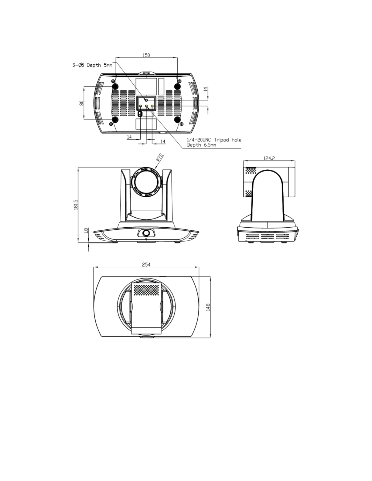
1.2 Dimensions
1.3 Power On
1) Power on: connect DC12V power supply adapter with NO.9 showed in Figure1.2.
2) Initialization: power on with power indicator light on and remote control receiver light blinking. Camera head
moves from bottom left to the central bottom, and then go to HOME position (intermediate position of both
horizontal and vertical), while the camera module initializes. When remote control receiver light stops blinking,
self-check is finished.
Note: If preset 0 is set, the camera automatically moves to the preset 0 position upon powering on.
Page 7
3
1.4 Video Output
AV-1364 has 2 options for video output: LAN, HD-SDI.
1) Video output from LAN.
a. Network cable connection port: AV-1364- No.3(panorama) and No.8(close-up) in Figure1.2.
b. Webpage Login: open your browser and enter 192.168.5.163(panorama) / 192.168.5.162(close-up) in the
address bar (factory default); press Enter to enter the login page; click on the “player is not installed, please
download and install!" and follow the installation instructions for installation. Then enter the user name admin
and password admin (factory default); press Enter to enter the preview page. Users can perform PTZ control,
video recording, playback, configuration and other operations.
2) HD-SDI video output
a. HD-SDI video cable connection: AV-1364- No.4(panorama) and No.5(close-up) in Figure1.2.
b. Connect the camera and the monitor via SDI video cable; video output will be available after initialization.
1.5 Basic Connection Instruction
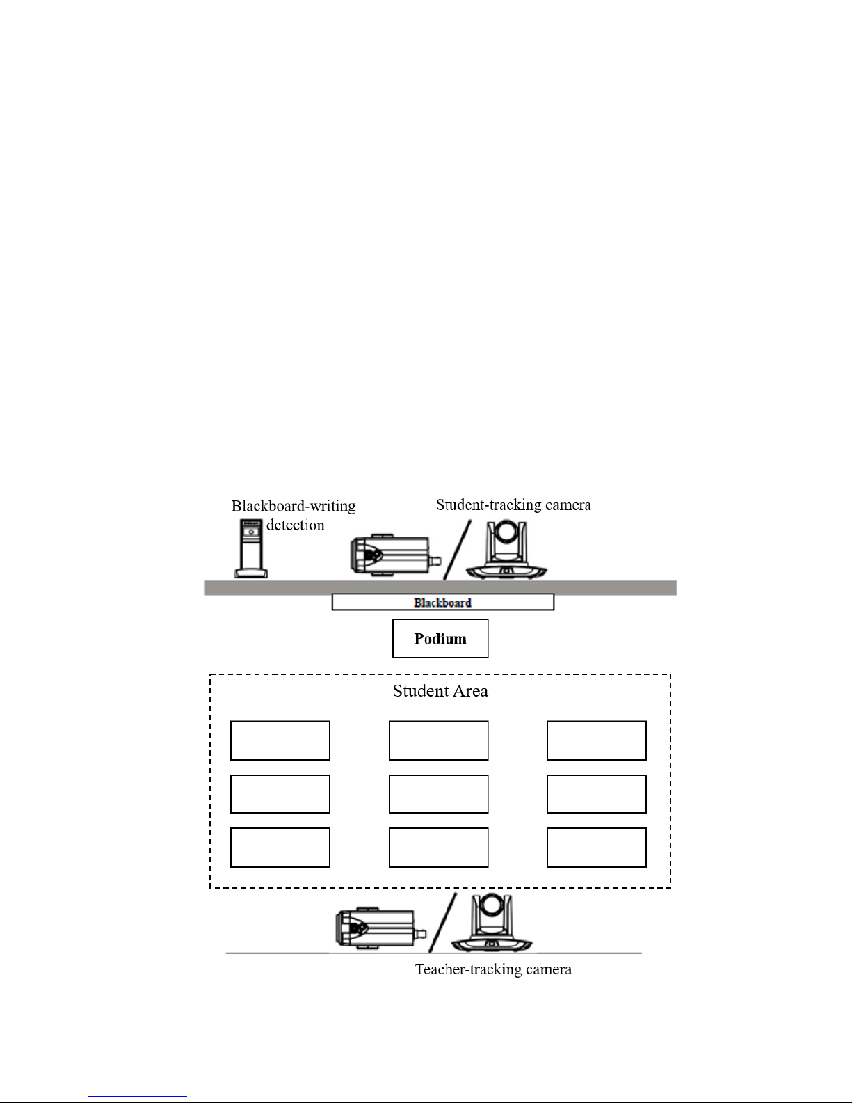
1) System layout:
• Blackboard-writing detection for future development;
• Student-tracking camera for option.
Page 8
4
Teacher-tracking camera is recommended to be installed 6-9ft from ground (panoramic lens to ground);
16-50ft from the blackboard/presentation screen (16-30ft: 4mm panoramic lens is recommended; 30-50ft:
6mm panoramic lens is recommended). Teacher-tracking camera should be installed close to the central axis
of the classroom as much as possible to get the best result of video.
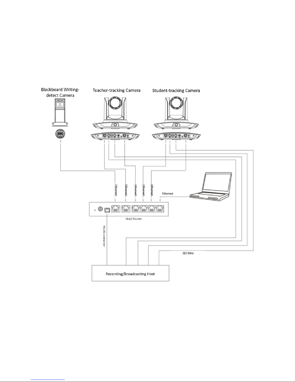
2) System wiring:
The AV-1364 provides a smart solution with only one camera for educational use. Customers can adjust their
system accordingly.
Page 9

5
2. Product Overview
2.1 System Introduction
AV-1364 SDI Auto-Tracking Camera is a dedicated smart camera solution in educational information industry.
It can be used alone, or be easily integrated into any smart-room system according to user settings. AV-1364
features a built-in high-speed processor and advanced image processing and analysis algorithms, to detect and track
target accurately and quickly. It adopts advanced ISP processing technique and algorithms, providing vivid images
with balanced brightness, distinct layering, high definition and color reduction. H.264/H.265 encoding supported. It
makes video fluent and clear even under less-than-ideal bandwidth conditions. AV-1364 offers flexible functions,
autonomous performance, simple use and minimum maintenance.
• Network control interface: control commands will be transmitted via network. It is suitable for
all-scenario user settings;
• Recognition algorithm unrelated to location: status detection and recognition of teachers and students
adopt unique smart partitioning algorithm to ensure that the result of detection and recognition is unrelated to
location;
• 2-way installation: with wall-mount or ceiling-mount, it supports both normal and upside-down
installation;
• All-in-one design: the built-in panoramic lens allows perfect combination of panoramic view and
close-up;
• Advanced tracking algorithm: it applies advanced human detection algorithms, image processing and
analytical algorithms for locking and tracking the target (intelligent image recognition library, scene adaptive
algorithm) to achievee stable, fast and accurate target tracking results;
• High immunity from interference: more diversified and flexible recognition shield settings ensure that
once tracking target is locked, it will not be affected by other moving objects or projector changes;
• Stable tracking: adjustable movement recognition sensitivity. Can be adjusted so that slight movement of
the target such as hand movement will not cause wrong operation of the camera;
• Self-adaptive: the tracking camera zooms according to the distance to target so that the visual image
maintains the proper size and scale;
• Super wide dynamic exposure: it prevents the tracking target dimming under strong light sources such as
the projector.
2.2 Main Features
2.2.1 Camera performance
• Full-scene solution: scenario demands;
• Full HD image: 1/2.8-inch high quality image sensor, with a maximum resolution 1920x1080;
• Wide-angle lens: 72.5° wide viewing angle with no distortion;
• Advanced focusing technique: the performance is quickly, accurately and steadily;
• Low noise & SNR: low-noise CMOS ensures super high signal to noise ratio of the video. With
advanced 2D and 3D noise reduction technology, noise is reduced and image resolution is guaranteed;
• Super quiet pan-tilt: high-precision stepping motor and motor driven controller ensure the pan-tilt
holder operate at low and stable speed without noise.
Page 10
6
2.2.2 Network performance
• Audio input interface: supports 16000, 32000, 44100, 48000 sampling rates; AAC, MP3, PCM audio
coding;
• Multiple audio/video compression: supports H.264/H.265 video compression; AAC, MP3 and PCM
audio compression; supports compression of resolution up to 1920x1080 with frame rate up to 60 fps and
2-channel 1920x1080p with 30 fps compression;
• Multiple network protocol: supports ONVIF, RTSP, RTMP protocols and RTMP push mode; easy to
connect to streaming media server (Wowza, FMS, etc.).
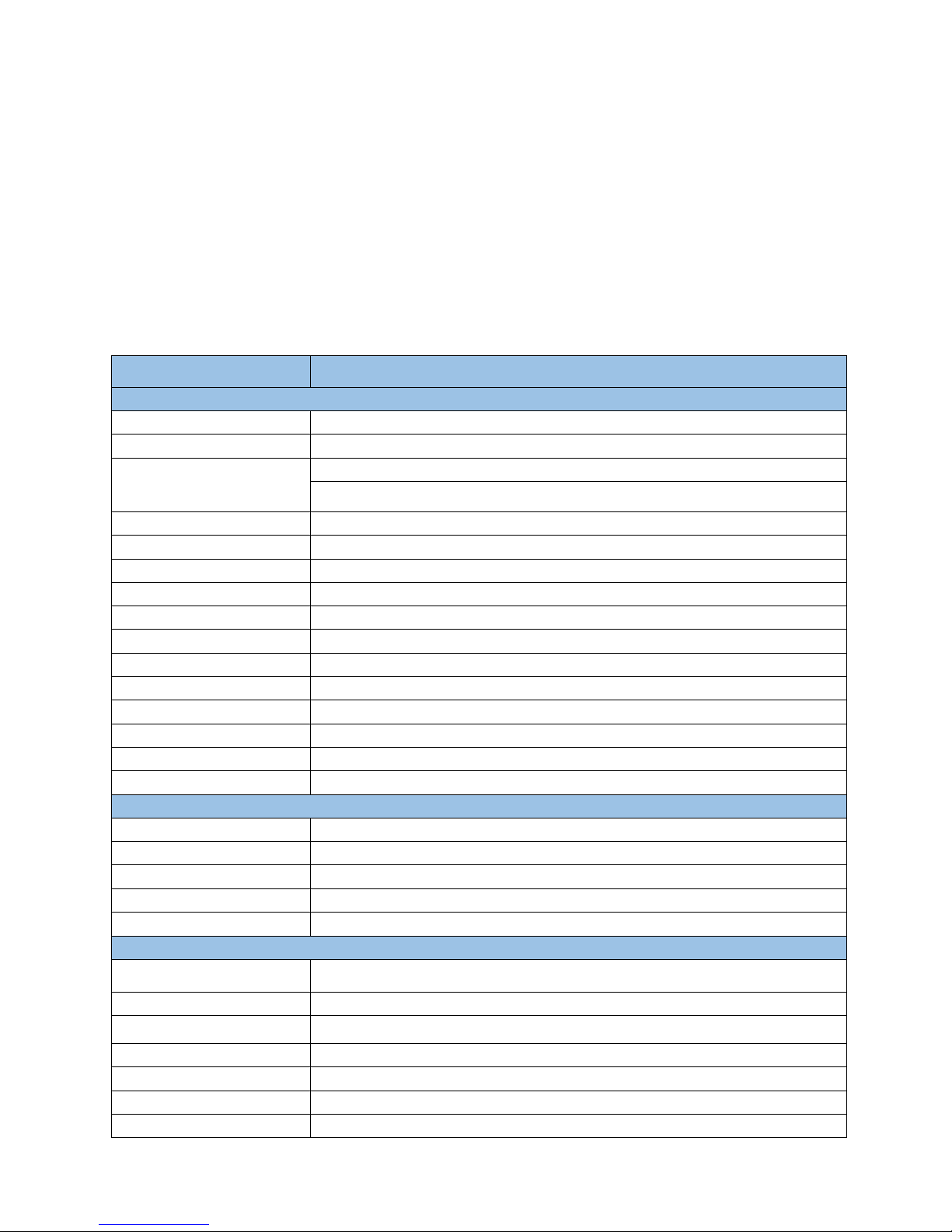
2.3 Technical Specifications
Model
AV-1364
Tracking Camera Parameter
Optical Zoom
20X, f = 4.7~94mm, F1.6~3.5
Sensor
1/2.8” high quality HD CMOS sensor
Effective Pixel
Video Format
16: 9 2.07 megapixel
1080P60/50/30/25/59.94/29.97;1080I60/50/59.94;720P60/50/30/25/59.94/29.97
View Angle
2.9°(tele) ~ 55.4°(wide)
Digital Zoom
10X
Minimum Illumination
0.5Lux (F1.8, AGC ON)
DNR
2D & 3D DNR
White Balance
Auto / Manual/ One Push/ 3000K/ 4000K/5000K/6500K
Focus
Auto/Manual
Aperture
Auto/Manual
Electronic Shutter
Auto/Manual
BLC
ON/OFF
WDR
OFF/ Dynamic level adjustment
Video Adjustment
Brightness, Color, Saturation, Contrast, Sharpness, B/W mode, Gamma curve
SNR
>55dB
Panoramic Camera Parameter
Sensor
1/2.8” high quality HD CMOS sensor
Effective Pixel
2.10 megapixel
Zoom
Manual
Output Interface
3G-SDI, LAN
View Angle (D/H/V)
112°/82°/57.6°
Input/Output Interface
Video Interfaces
3G-SDI, LAN
Image Code Stream
Dual stream output
Video Compression Format
H.264, H.265
Control Signal Interface
RS-232, RS-485(shared w/ RS-232)
Control Protocol
VISCA/ Pelco-D/ Pelco-P; Baud Rate: 115200/9600/4800/2400bps
Audio Input Interface
Double track 3.5mm linear input
Audio Compression Format
AAC/MP3/PCM Audio compression
Page 11
7
HD IP Interface
100M IP port(100BASE-TX), Support Visca protocol control through IP port
Network Protocol
RTSP, RTMP, ONVIF, GB/T28181
Power Interface
HEC3800 outlet (DC12V)
PTZ Parameter
Pan Rotation
-170°~+170°
Tilt Rotation
-30°~+90°
Pan Control Speed
0.1~100°/sec
Tilt Control Speed
0.1~45°/sec
Preset Speed
Pan: 100°/sec, Tilt: 45°/sec
Preset Number
255 presets (10 presets by remote controller)
Other Parameter
Supply Adapter
Input: AC110~220V Output: DC12V/2.5A
Input Voltage
DC12V±10%
Input Current
1.5A(Max)
Consumption
18W (Max)
Store Temperature
-10ºC~+60ºC
Store Humidity
20%~95%
Working Temperature
-10ºC~+50ºC
Working Humidity
20%~80%
Dimension
254mm*144mm*174mm
Weight
1.50KG
Remote Operation (IP)
Remote Upgrade, Reboot and Reset
Accessory
Power supply, RS232 control cable, Remote controller, Manual, Warranty card
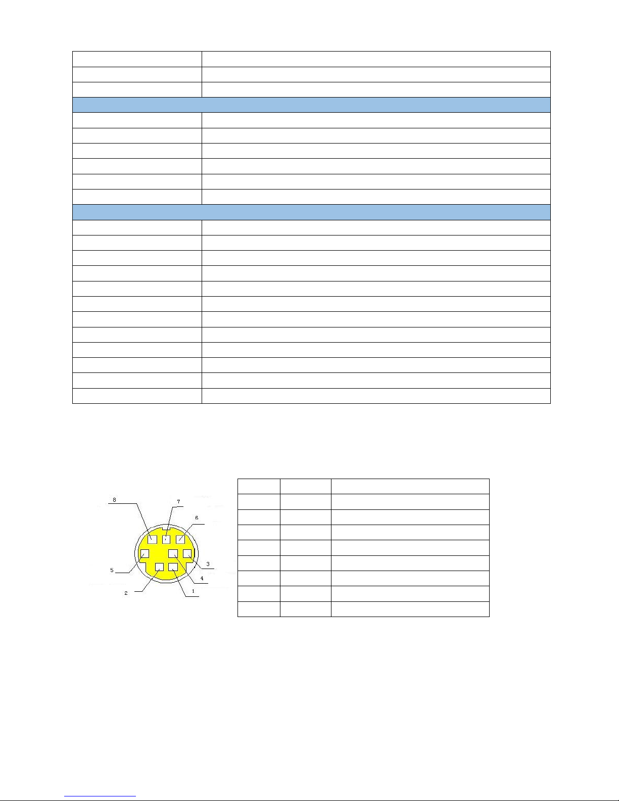
2.4 Interface Instructions
2.4.1 RS-232 mini-DIN 8-pin port definition
NO.
Port
Definition
1
DTR
Data Terminal Ready
2
DSR
Data Set Ready
3
TXD
Transmit Data
4
GND
System Ground
5
RXD
Receive Data
6
GND
System Ground
7
IR OUT
IR Commander Signal
8
NC
No Connection
Page 12
8
3. Application Instructions
3.1 Remote Control
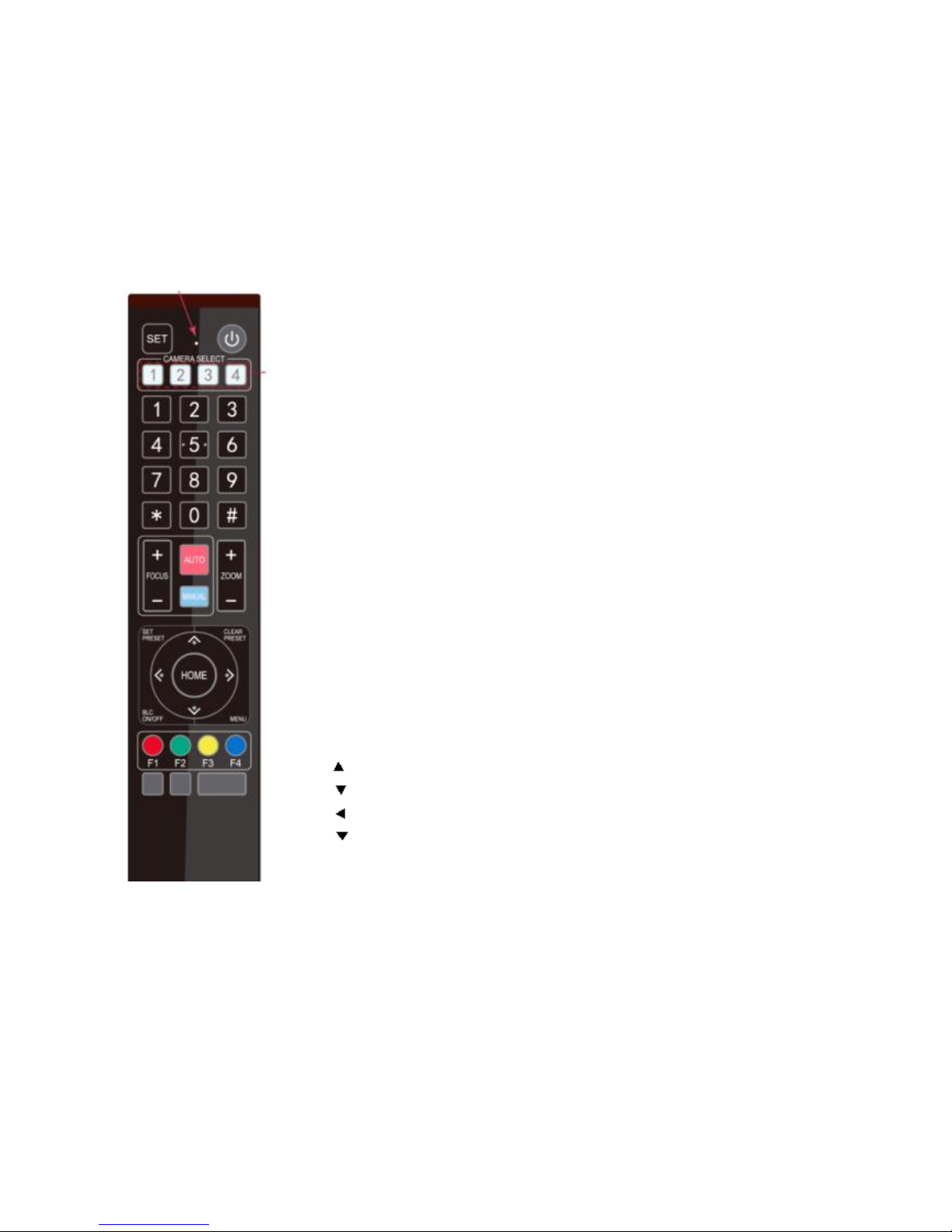
3.2.1 Key Illustrations
Before using the remote to control AV-1364, the user needs to log in via IP first and turn
off the tracking mode (will be instructions in 4. Configuration Tools).
• Standby key
After 3-sec long press, the camera will enter the standby mode. Long press the key
again for 3 secs, the camera will initialize again and return back to HOME position
(Note: when power-on mode is turned on and Preset 0 is set, if there is no operation
after 12 secs, the camera will automatically rotate to the specified preset position).
• Camera address selection
Select the specific camera which the user wants control.
• Number key
Set or run one of the preset positions (0~9).
• 【*】and【#】key
Key combination is used to restore the default settings.
• Focus control key
Auto focus: 【AUTO】to enter auto focus mode.
Manual focus: 【MANUAL】 to manually adjust the camera focus by pressing
【FOCUS+】or【FOCUS-】.
• Zoom control key
【ZOOM+】: near lens
【ZOOM-】: far lens
• Set or clear preset key:
Set preset position: 【SET PRESET】+ number key (0~9).
Clear preset position: 【CLEAR PRESET】+ number key (0~9).
• Pan/tilt control key
Press key: up
Press key: down
Press key: left
Press key: right
“HOME” key: return to the center position or enter the submenu.
• BLC control key
【BLC ON/OFF】: turn on or off the back light.
• Menu settings
【MENU】: to open or close the OSD menu.
Enter/exit the OSD menu or return to the previous menu.
• Camera IR remote control address settings
【*】+【#】+【F1】: Camera Address No.1
【*】+【#】+【F2】: Camera Address No. 2
【*】+【#】+【F3】: Camera Address No. 3
【*】+【#】+【F4】: Camera Address No. 4
• Key combination functions
1) 【#】+【#】+【#】: Clear all presets
2) 【*】+【#】+【6】: Restore factory defaults
Page 13
9
3) 【*】+【#】+【9】: Flip switch
4) 【*】+【#】+ 【AUTO】: Enter the aging mode
5) 【*】+【#】+【3】: Set menu language to Chinese
6) 【*】+【#】+【4】: Set menu language to English
7) 【*】+【#】 + 【MANUAL】: Restore the default user
name, password, and IP address
8) 【#】 +【#】+【0】: Switch the video format to
1080P60
9) 【#】+【#】+【1】: Switch the video format to 1080P50
10) 【#】+【#】+【2】: Switch the video format to 1080I60
11) 【#】+【#】+【3】: Switch the video format to 1080I50
12) 【#】+【#】+【4】: Switch the video format to 720P60
13) 【#】+【#】+【5】: Switch the video format to 720P50
14) 【#】+【#】+【6】: Switch the video format to
1080P30
15) 【#】+【#】+【7】: Switch the video format to 1080P25
16) 【#】+【#】+【8】: Switch the video format to 720P30
17) 【#】+【#】+【9】: Switch the video format to 720P25
3.2.2 Applications
When initialization is complete, the camera can receive and execute IR commands. Press the ON/OFF button on the
remote control, the indicator light will be flashing; release the button, the indicator light stops flashing. The user
can control the pan/tilt/zoom settings and run preset positions via IR remote control.
Key instructions:
1. In the instructions below, “press the key” means a click rather than a long-press. A special note will be given
if a long-press for more than 1 sec is required.
2. When a key-combination is required, do it in sequence. For example, “【*】+【#】+【F1】” means press “【*】”
first and then “【#】” and lastly press “【F1】”.
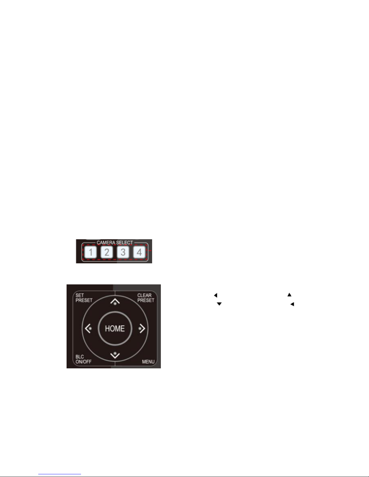
1) Camera Selection
Select the camera address which the user wants to
control.
2) Pan/Tilt Control
Up: press Down: press
Left: press Right: press
Back to center position: press【HOME】
Press and hold the up/down/left/right key, the pan/tilt
will keep running, from slow to fast, until it runs to the
endpoint. The pan/tilt running stops as soon as the key is
released.
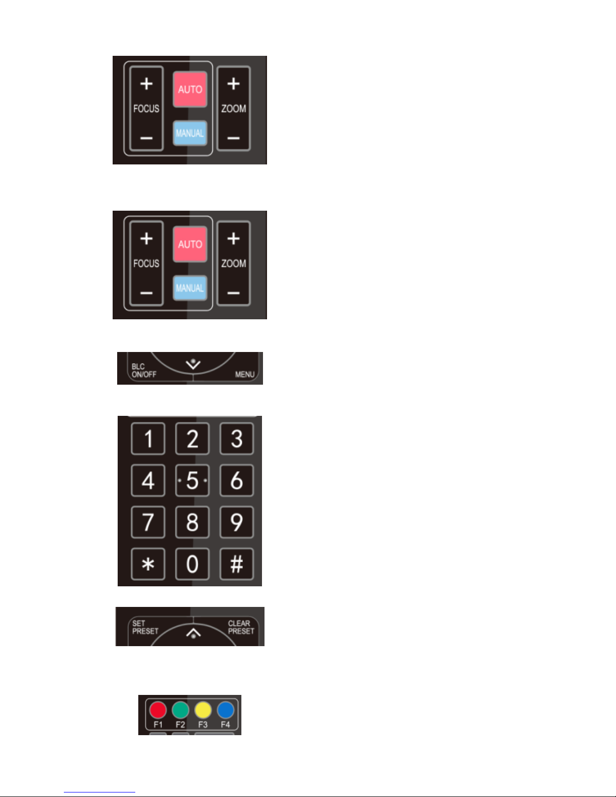
3) Zoom Control
Page 14
10
Zoom-in: press 【ZOOM+】key
Zoom-out: press【ZOOM-】key
Press and hold the key, the camera will keep zooming
in/out. It stops as soon as the key is released.
4) Focus Control
Focus (near): press 【FOCUS+】(valid only in manual
focus mode)
Focus (far): press【FOCUS-】(valid only in manual focus
mode)
Auto focus: support
Manual focus: support
Press and hold the key, the action of focus will keep
adjusting. It stops as soon as the key is released.
5) BLC Settings
BLC ON/OFF: support
6) Presets Setting, Running and Clearing
1. Preset setting: to set a preset position, the user should
press【SET PRESET】first, then press the number key
0~9 to set the corresponding preset.
Note: 10 preset positions are available in total by using
the remote control.
2. Preset running: press a number key 0~9 directly to
run the corresponding preset position.
Note: action in vain if the selected preset position does
not exist.
3. Preset clearing: the user can press【CLEAR PRESET】
first, then press the number key 0~9 to clear the
corresponding preset.
Note: press【#】three times in succession to clear all the
presets.
7) Camera Remote Controller Address Settings
【*】+【#】+【F1】: Camera Address No.1
【*】+【#】+【F2】: Camera Address No. 2
【*】+【#】+【F3】: Camera Address No. 3
【*】+【#】+【F4】: Camera Address No. 4
Page 15

11
3.3 Menu Settings
3.3.1 Main Menu
In normal working mode, press【MENU】to display the menu. The user can scroll the arrow to point at or highlight
the selected item.
Language: menu language setting, Chinese / English
Setup: system settings
Camera: camera settings
P/T/Z: pan/tilt/zoom settings
Video Format: video output format settings
Version: camera version
Restore Default: restore default settings
【↑↓】Select: select menu 【← →】: exit/enter submenu
【Menu】: press 【Menu】to return to the previous menu
【Home】: press 【Home】to confirm
3.3.2 System settings
Move the pointer to 【Setup】in the Main Menu, click【Home】to enter System Settings as shown below.
MENU
===============
Language English
(Setup)
(Camera)
(P/T/Z)
(Video Format)
(Version)
(Restore Default)
[↑↓]Select [← →]Change Value
[Menu]Back [Home]OK
Page 16

12
Protocol: VISCA/ Pelco-P/ Pelco-D/ Auto
Visca Address: VISCA=1~7/ Pelco-P=1~64/ Pelco-D =1~64
Visca Address Fix: On/Off
Baud rate: 2400/4800/9600/115200
3.3.3 Camera settings
Move the pointer to the 【Camera】 in the Main Menu, click 【Home】to enter camera settings menu as shown
below.
CAMERA
===============
(Exposure)
(Color)
(Image)
(Focus)
(Noise Reduction)
Style default
[↑↓]Select [← →]Change Value
[Menu]Back [Home]OK
SETUP
===============
Protocol Auto
Visca Address 1
Visca Address Fix OFF
PELCO-P Address 1
PELCO-D Address 1
Baud rate 9600
[↑↓]Select [← →]Change Value
[Menu]Back
Page 17

13
1) Exposure Settings
Move the pointer to 【Exposure】in the Main Menu, click 【Home】 to enter the Exposure Setting menu as shown
below.
Mode: auto/ manual/ shutter priority/ iris priority/ brightness priority.
EV: exposure compensation setting, ON/ OFF (valid in Auto mode)
Compensation Level: -7~7 (valid when EV is ON)
BLC: ON/ OFF (valid in Auto mode)
Flicker: OFF/ 50Hz/ 60Hz (valid in Auto/ Shutter priority/ Brightness priority modes)
G. Limit: gain limit, 0~15 (valid in Auto/ Shutter priority/ Brightness priority modes)
Shutter Priority: 1/25, 1/30, 1/50, 1/60, 1/90, 1/100, 1/120, 1/180, 1/250, 1/350, 1/500, 1/1000, 1/2000, 1/3000,
1/4000, 1/6000, 1/10000 (valid in Manual/ Shutter priority modes)
IRIS Priority: OFF/ F11.0/ F9.6/ F8.0/ F6.8/ F5.6/ F4.8/ F4.0/ F3.4/ F2.8/ F2.4/ F2.0/ F1.8 (valid in Manual/ Iris
priority modes)
DRC: dynamic range, 1~8/ OFF.
2) Color Settings
Move the pointer to 【Color】 in the Main Menu, click 【Home】to enter the Color Settings menu as shown below.
EXPOSURE
================
Mode Auto
EV OFF
BLC OFF
Flicker 50Hz
G.Limit 3
DRC 2
[↑↓]Select [← →]Change Value
[Menu]Back
Page 18

14
WB Mode: auto/ 3000K/ 4000K/ 5000K/ 6500K/ manual/ one-key white balance.
RG Tuning: red gain tuning, -10~10 (valid when white balance mode is Auto)
BG Tuning: blue gain tuning, -10~10 (valid when white balance mode is Auto)
RG: red gain, 0~255 (valid when white balance mode is Manual)
BG: blue gain,0~255 (valid when white balance mode is Manual)
Saturation: 60%/ 70%/ 80%/ 90%/ 100%/ 110%/ 120%/ 130%/ 140%/ 150%/ 160%/ 170%/ 180%/ 190%/ 200%
Hue: 0~14
AWB Sensitivity: high/ medium/ low (valid white balance mode is Auto)
3) Image Settings
Move the pointer to 【Image】in the Main Menu, click 【Home】 to enter the Image settings menu as shown below.
IMAGE
===============
Brightness 7
Contrast 7
Sharpness 4
Flip-H OFF
Flip-V OFF
B&W-Mode Color
Gamma Default
DZoom OFF
DCI Close
[↑↓]Select [← →]Change Value
[Menu]Back
COLOR
================
WB Mode Auto
RG Tuning 0
BG Tuning 0
Saturation 100%
Hue 7
AWB Sensitivity Low
[↑↓]Select [← →]Change Value
[Menu]Back
Page 19

15
Brightness: 0~14 Contrast: 0~14 Sharpness: 0~15
Flip-H: horizontal flip, On/Off Flip-V: vertical flip, On/Off
B&W mode: color/ black&white
Gamma: default/ 0.45/ 0.50/ 0.55/ 0.63
DZoom: digital zoom, On/ Off
DCI: dynamic contrast: Off/ 1~8
4) Focus
Move the pointer to the 【Focus】in the Main Menu, click 【Home】to enter the Focus Settings menu as shown
below.
Focus mode: auto/ manual AF-Zone: up/ center/ low AF-Sensitivity: high/ medium/ low
5) Noise Reduction
Move the pointer to 【Noise Reduction】in the Main Menu, click 【Home】 to enter the Noise Reduction settings
menu as shown below.
NR-2D: 2D noise reduction, auto/ off/ 1~7
NR-3D: 3D noise reduction, off/ 1~8
Dynamic Hot Pixel: off/ 1~5
NOISE REDUCTION
================
NR-2D 3
NR-3D 5
Dynamic Hot Pixel OFF
[↑↓]Select [← →]Change Value
[Menu]Back
FOCUS
================
Focus Mode Auto
AF-Zone Center
AF-Sensitivity Low
[↑↓]Select [← →]Change Value
[Menu]Back
Page 20

16
3.3.4 P/T/Z
Move the pointer to【P/T/Z】in the Main Menu, click 【Home】to enter the P/T/Z settings menu as shown below.
Speed by zoom: only effective with remote control, On/Off. Press 【zooming+】, PT running speed decreases
proportionally
Zoom speed: set the zoom speed with remote control, 1~8
Image Freezing: On/Off
Acc curve: accelerating curve, fast/slow
3.3.5 Video Format
Move the pointer to 【Video Format】 in the Menu, click 【Home】 to enter the Video Format menu as shown
below.
Note: Please exit the menu and reboot the camera after modifications. Settings will be saved and recalled upon
VIDEO FORMAT
================
1080P60 1080P50
1080I60 1080I50
1080P30 1080P25
720P60 720P50
720P30 720P25
1080P59.94 1080I59.94
1080P29.97 720P59.94
720P29.97
[↑↓]Select
[Menu]Back [Home]OK
P/T/Z
=================
Speed by zoom ON
Zoom speed 8
Image Freezing OFF
Acc Curve Slow
[↑↓]Select [← →]Change Value
[Menu]Back
Page 21

17
powering off/on.
3.3.6 Version
Move the pointer to 【Version】 in the Main Menu, click 【Home】 to enter the Version menu as shown below.
Note: version information could be different according to different models and manufacture dates.
MCU Version: display MCU version information
Camera Version: display camera version information
AF Version: display the focus version information
Lens: display the lens zoom
3.3.7 Restore Default
Move the pointer to 【Restore Default】 in the Main Menu, click 【Home】 to enter the Restore Default menu as
shown below.
Restore Default: YES/NO (color setting and video format cannot be restored to default settings)
Note: if the remote address is not set to 1 but another number: 2, 3, or 4, the corresponding camera address will be
restored to 1 when all parameters or system parameters are restored. User should change the remoter address to 1
(【Camera】+【1】).
RESTORE DEFAULT
=================
Restore Default? NO
[↑↓]Select [← →]Change Value
[Menu]Back [Home]OK
VERSION
================
MCU Version 2.0.0.15 2015-12-18
Camera Version 2.0.0.13 2015-12-18
AF Version 2.0.0.6 2015-12-11
Lens 12X(20X)
[Menu]Back
Page 22
18
4. Configuration Tools
4.1 Set IP address of the tracking camera
Connect the camera to a hub via Ethernet cables, then connect the computer.
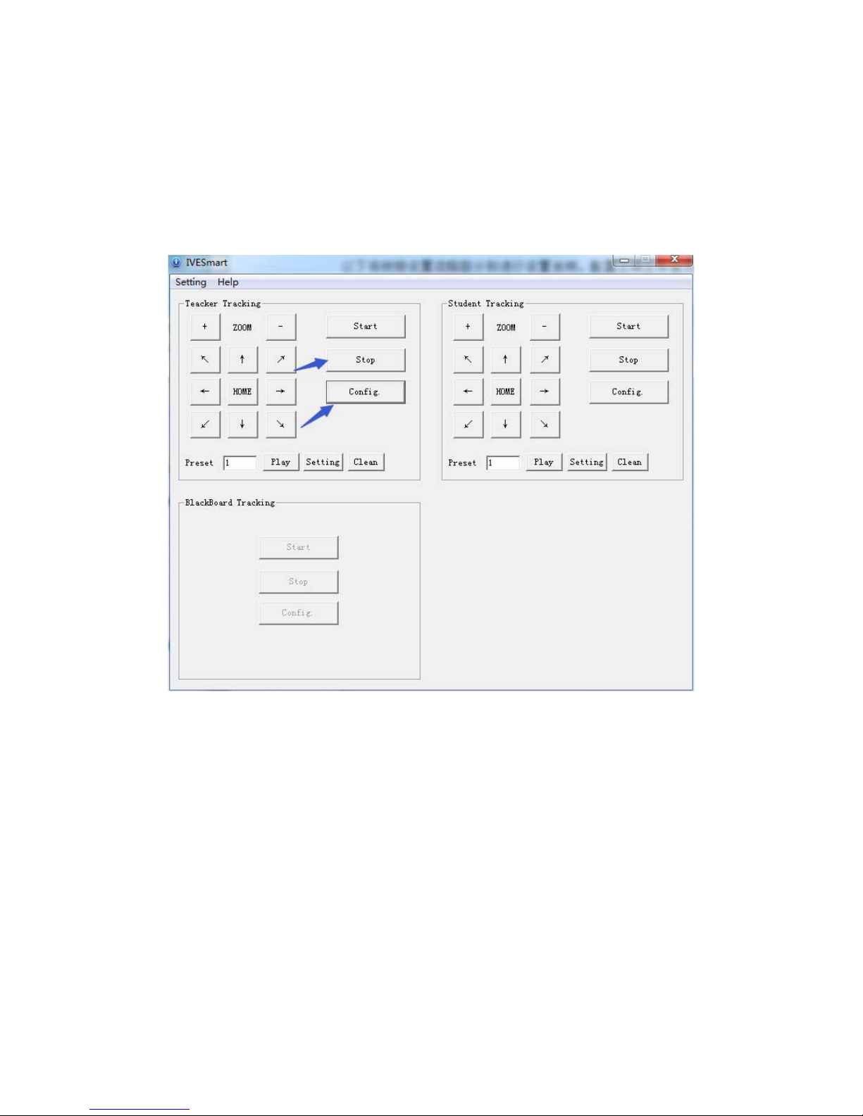
Open IVESmart configuration tool.
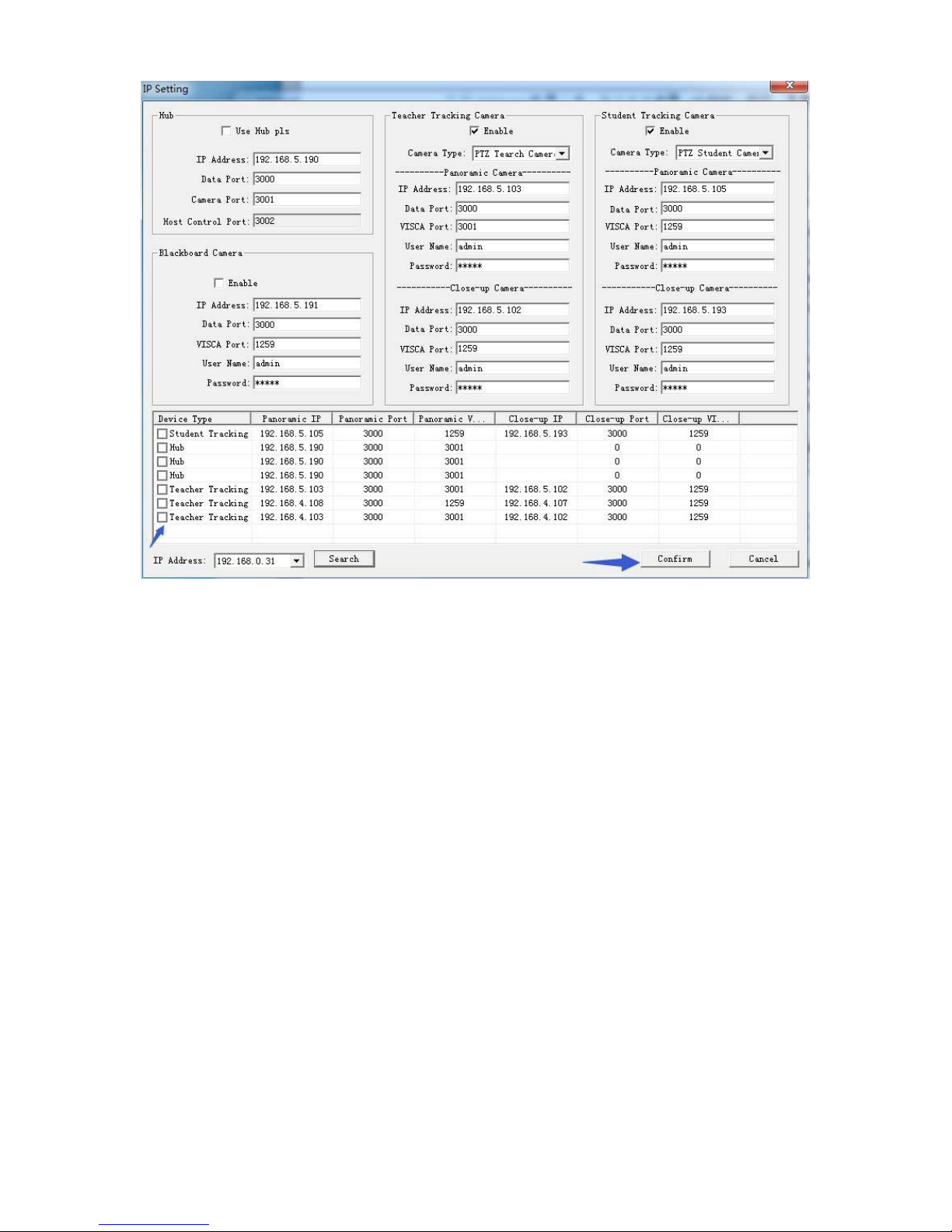
Click Settings -> IP address -> Search successively (Figure 4.1-1), the configuration interface will display all valid
devices in the LAN, check the type of device to be configured and click Confirm.
Note: Computer for operating IVESmart tool should be in the same LAN with the camera being configured.
Confirm the wire connections are correct, then click 【search】 on the lower left corner. The corresponding camera
will appear in the window with the port number and IP information. Double-click the showing device, IVESmart
will automatically configure the information of the corresponding camera. Web login user name and password is
administrator (default ), can be modified as needed.
After configuration is done, click "OK" in the lower right corner to complete the IP address configuration.
Page 23
19
Figure 4.1-1 IP Configuration Interface
Page 24
20
4.2 System Configuration
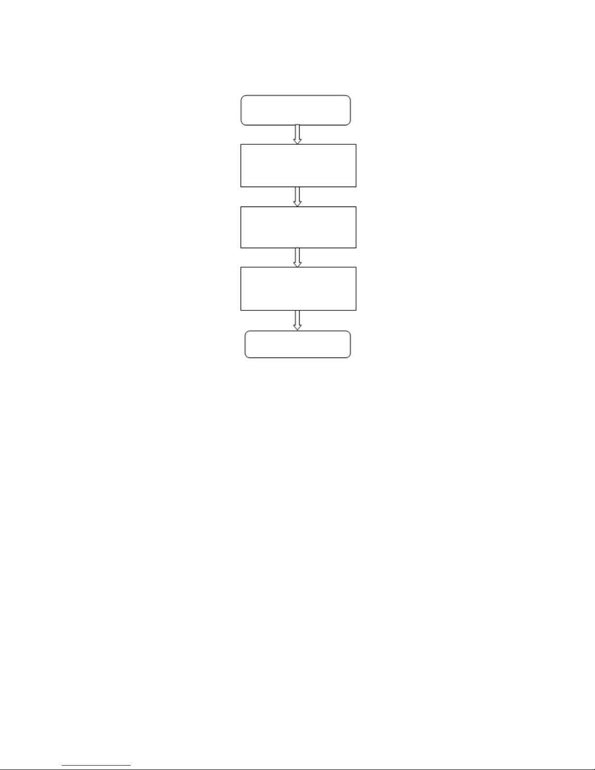
4.2.1 Flowchart of the process
Podium Position: The “Podium Position” is set to the default start point of tracking. Adjust zoom and focus so that
when the teacher is standing at the podium, he/she appear the appropriate size and height in the close-up image. Set
the close-up position to be the “Podium Position”. After the camera is powered on, it will automatically turn to the
“Podium Position” and start tracking. When the target is lost, the user can set the camera to go back to the “Podium
Position” (see "Basic Parameter Settings"). Automatic zoom function of the camera also takes the “Podium
Position” as a reference. Please be sure to carefully set the “Podium Position”. The “Podium Position" is recognized
as "Preset 1" by the camera.
Panorama Position: The “Panorama Position” is set to the default panoramic preset point. It can also be modified
and set to any other preset location. When the target is lost, the user can set the camera to go back to the “Panorama
Position” (see "Basic Parameter Settings"). The “Panorama Position" is recognized as "Preset 0" by the camera.
Stop tracking
Set Panoramic & Close-up
(Podium) presets
Set tracking & shielding
areas (Podium)
Set tracking parameters
Start tracking
Page 25
21
4.2.2 Configuration Interface
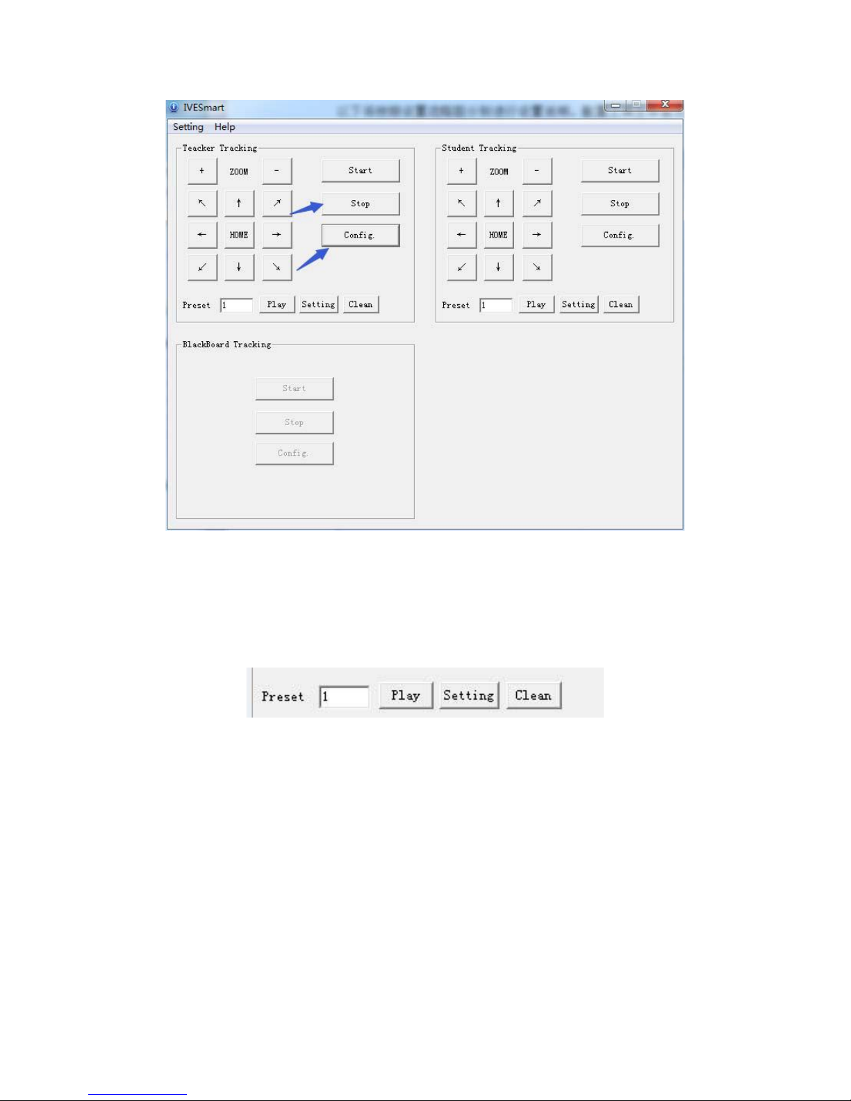
【↑↓← →】 PTZ and zoom settings. Click the arrow keys to control the PTZ movement of the tracking camera;
Press 【HOME】 and the tracking camera will return to the center position; Click 【+】/【-】to zoom in/out.
【Start】Start tracking. When the camera stops tracking the target, or after configuration, click 【Start】 to start
tracking again.
【Stop】Stop tracking. Click 【Stop】to stop tracking the target.
【Config.】Click 【Configure】to enter the configuration interface.
【Preset】Call/ Set/ Clear preset positions.
Click 【Stop】first to exit auto-tracking mode, then click 【Config.】to enter Configuration interface.
Page 26
22
4.2.3 Parameter Setup
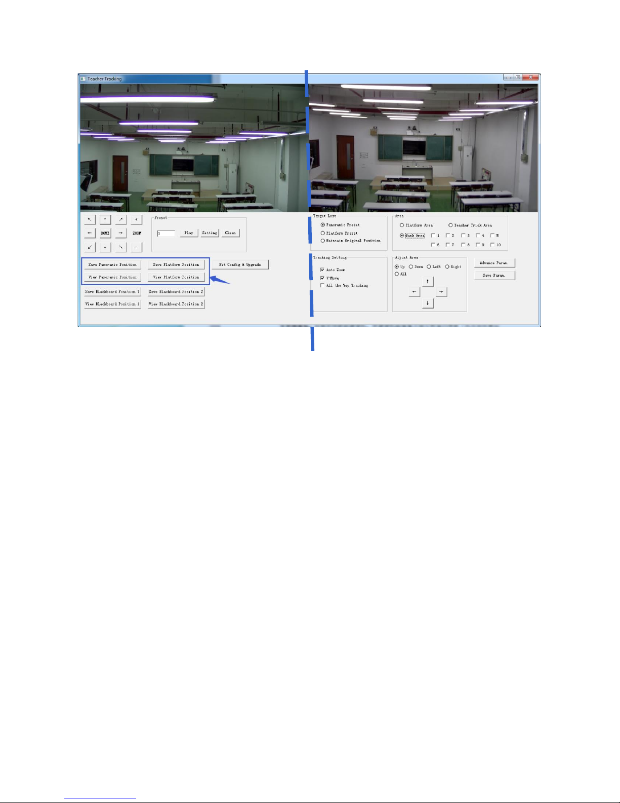
1) Close-up/ Tracking view configuration (the left half of the interface)
In the box indicated by the arrow (see the interface below), there are 4 buttons which are used to set preset
positions for both close-up and panoramic view.
Click 【View Platform/Panoramic Position】, then adjust 【↑↓← →】 position and zoom so that the target can
be best capture. Click 【Save Platform/Panoramic Position】to save settings.
Note: Platform refers to the close-up view.
Platform preset: Adjust 【↑↓← →】 and zoom 【+ -】of the tracking camera to get the desired visual result of
camera image (we suggest that the teacher stand in the middle of podium, if any). Click 【Save Platform Position】.
Once the auto-tracking mode starts, the size of teacher in Platform preset is used as a reference. When tracking
target lost in sight, the close-up image will go back to Platform preset position.
Panoramic preset: Adjust 【↑↓← →】 and zoom 【+ -】again to capture as much as a panoramic view of the
classroom (or any position). When tracking target lost in sight, the close-up image will go back to Panoramic preset
position.
Preset for blackboard-writing: for future use.
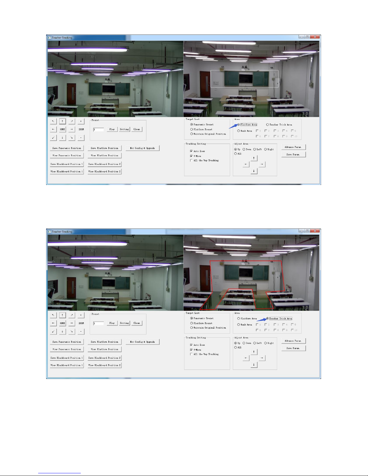
2) Set Panoramic Area
Platform area: It is the area tracked once close-up lens start up tracking. It is blackboard area on
platform generally so as to ensure that when teacher is on platform his upper body is displayed
within setting area, and it will not exceed lower margin of platform area when students in the first
row sit down. See Figure 5.2-3.
Page 27
23
Tracking area: Tracking area means scope of tracking teacher. When the tracking target goes
out of the tracking area, it will be considered tracking target losing. The tracking area can be
set into polygon according to certain environment conditions, or set student area outside of
tracking area. See Figure 5.2-4:
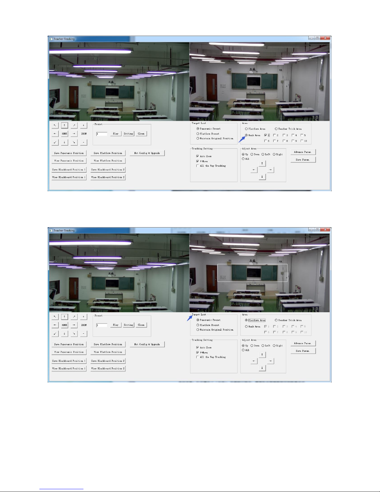
Mask area: Mask area is usually the area which may impact result of teacher tracking, such
as places which may have dynamic changes such as TV, projector, doors and windows. See
Figure 5.2-5:
Page 28
24
3. Set tracking parameters
Target lost: when target loses, the close-up lens will return to designated preset position. This
preset position can be panoramic preset, platform preset or maintain original position.
Tracking settings:
Auto zoom: In open mode (checked), during tracking, the camera will zoom automatically
according to target distance; in off mode (unchecked), during teacher tracking, zoom remains
the value set during platform preset.
V-move: In open mode (checked) and during teacher tracking, the camera will adjust its angle
of elevation according to height of tracking target; in off mode (unchecked) and during
teacher tracking, angle of elevation remains the value set during platform preset. If a teacher
will not step down platform in class, we suggest turning off auto zoom and v-move.
Page 29

25
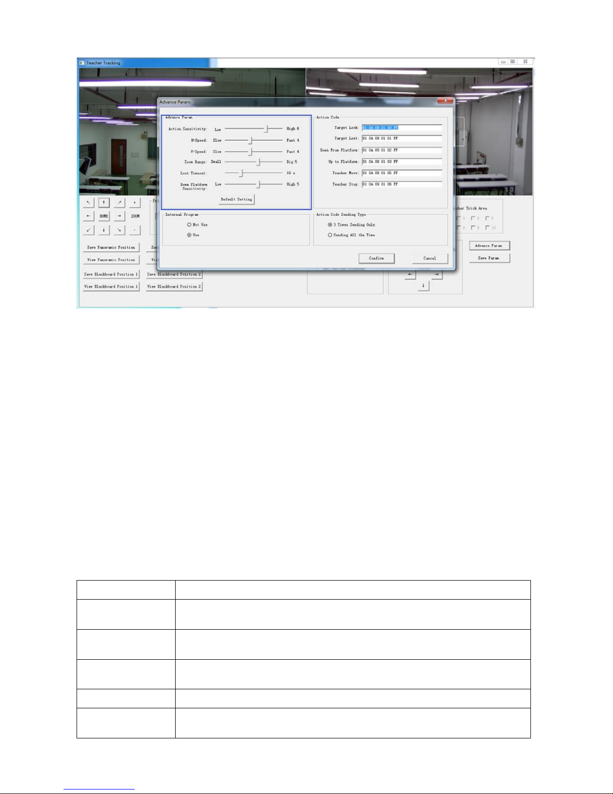
Advance parameters:
Action sensitivity: In teacher tracking mode, it is the action range required to trigger tracking
camera when the tracking target changes from stationary state to motion state. The higher the
action sensitivity, the smaller movement of tracking target that will trigger camera’s tracking
motion.
H-speed: It means speed of tracking camera for horizontal tracking.
V-speed: It means speed of tracking camera for vertical tracking.
Zoom range: The bigger the range, the higher zoom extent required for camera when tracking
target steps down platform.
Lost timeout: It means time required (5s by default) for tracking camera to perform target lost
action when target is lost (optional: return to panorama preset, platform preset, or remain
original position).
Down platform sensitivity: It is used for determining if teacher steps down platform. The
lower the sensitivity, the longer teacher’s distance to blackboard it required to trigger teacher
down platform action.
Page 30
26
For settings of action code, refer to “7 Description of connecting recording and broadcasting
host”.
After setting, click Save Parameter. It allows to entering advance parameter settings column to
change configuration value to obtain the best result subject to specific scenes and customer
demand.
4.2.4 Configuration
Click Configuration to enter the device parameter setting page.
There are options as listed below: local configuration, audio configuration, video configuration, network
configuration, PTZ configuration, internet access configuration, system configuration. For detailed description, see
the following table.
Menu
Explanation
Local configure
Including video preview mode, record video packing time, record video storage route
settings etc.
Audio configure
Including audio compressing format, sampling frequency, sampling precision,
compressing code rate settings etc.
Video configure
Including video encoding, video parameters, character-overlapping, character size,
video output setting etc.
Network configure
Including basic parameters, Ethernet, DNS, wireless network setting etc.
System configure
Including equipment property, system time, user management, version update, Reset,
Reboot device settings etc.
Page 31

27
1) Local configuration
Video Preview Mode: user can choose real-time priority or fluency priority. The delay will be smaller when under
real time priority mode, and fluency will be better when under fluency priority mode. Setting based on user’s need
(default value: real time best (1), real time normal (2), fluency normal (3), fluency good (4) and fluency best (5)).
Recording Packing Time (minute): set recording video packing time (default is 3, range from 1~120 minutes).
Recording/Snapshot File Storage Route: set local recording video/snapshot file storage route (default:
D:\MyIPCam\).
Click “Save” button to let setting changes take effects.
2) Audio configuration
Switch: choose to enable/disable the audio.
Compressing Format: set audio compressing format, and the device will reboot automatically after changing
(default: MP3, other options: PCM, AAC).
Sampling Frequency: set sampling frequency, and the device will reboot automatically after changing (default:
44100, other options: 16000, 32000 and 48000).
Sampling Precision: set sampling precision (default: 16bits).
Compressing Code Rate: set audio compressing code rate (default: 64bits, other options: 32, 48, 96, 128bits).
Note: click “Save”, and it will show the message “Enable has changed. Restart the device to take effect after the
success of the save.”. Please reboot the camera for the changes to take effects.
4.2.5 Video configuration
1) Video Encoding
Code Stream: for different video output mode settings, use different streams (main stream, secondary stream)
accordingly.
Compression Format: set the video compression format, save and reboot to take effect (main/secondary stream
default: H.264, other options: H.265).
Video Size: set video image resolution, save and reboot to take effect (main stream default 1920 * 1080, other
options: 1280 * 720; secondary stream default 640*320, other options: 320*180, 1280*720).
Stream Rate Control: set rate control mode, save and reboot to take effect (main/secondary stream default:
variable bit rate, other options: fixed rate).
Image Quality: set image quality. Image quality can be changed only when rate control is set to variable bit rate
(main stream default: better; secondary stream default: good; other options: best, better, good, bad, worse, worst).
Rate (Kb/s): set the video bit rate (main stream default: 8192Kb/s, other options: 64-20480Kb/s; secondary stream
default: 2048Kb/s, other options: 64-8192Kb/s).
Frame Rate (F/S): set the video frame rate (main/secondary stream default: 25F/S; other options for main stream:
5-60F/S; other options for secondary stream: 5-30F/S).
Key Frame Interval: set the key frame interval (main/secondary stream default: 75F, other options for main
stream: -300F; other options for secondary stream: 1-150F).
Key Frame Minimum QP: default: 10, other options: 10~51.
Click "Save". Settings will take effect after the message "saved successfully" shows.
2) Stream Release
Switch: to turn on/off the main/secondary stream.
Protocol: main/secondary stream applies RTMP protocol.
Page 32

28
Host Port: server port number (default 1935, other options: 0-65535).
Host Address: server IP addresses (default 192.168.5.11).
Stream Name: choose a different stream name (live/av0, other options: live/av1).
User: set the user name.
Password: set the password.
Click "Save". Settings will take effect after the message "saved successfully" shows.
RTSP obtaining path: rtsp: // device IP address: 554 / live / av0 (av0 main stream; av1 secondary stream).
3) Video Parameters
a. Focus: focus mode, focus range, focus sensitivity can be set.
Focus Mode: set the focus mode (default: auto, other options: manual).
Focus Range: set the focus range (default: middle, other options: upper, lower).
Focus Sensitivity: set the focus sensitivity (default: low, other options: high, medium).
b. Exposure: exposure mode, exposure compensation, back light compensation, anti-flicker, gain limit, DRC,
shutter speed, aperture value and brightness can be set.
Exposure Mode: set the exposure mode (default: automatic, other options: manual, shutter priority, aperture
priority, brightness priority).
Exposure Compensation: exposure compensation setting is active when it is auto status (default: off).
Exposure Compensation Value: set the exposure compensation value. Valid when it is set for auto (default: -7,
other options: -7 ~7).
BLC: set back light compensation, valid when it is under auto mode (default: off).
Anti-flicker: set anti-flicker mode, valid when under automatic, aperture or brightness priority mode (default:
50Hz, other options: closed, 60Hz).
Gain Limit: set the gain limits. Auto, active when it is under aperture or brightness priority mode (default: 7, other
options: 0-15).
Dynamic Range: set the dynamic range (default: 2, other options: 1-8 and OFF).
Shutter Speed: active when it is under manual or shutter-priority mode (default: 1/90, other options: 1/90, 1/100,
1/1/120/180, 1/250, 1/350, 1/500, 1/725, 1/1000, 1/1500, 1/2000, 1/3000, 1/4000, 1/6000, 1/10000).
Aperture Value: set the aperture value. Active when it is under manual or aperture-priority mode (default: F1.8,
other options: closed, F9.6, F8.0, F6.8, F5.6, F4.8, F4.0, F3.4, F2.8, F2.4, F2.0, F1.8).
Brightness: set the brightness value. Active when it is under brightness priority mode (default: 7, other options:
0-23).
c. Color: white balance, saturation, hue, white balance sensitivity, red tuning, blue tuning, red gain and blue
gain can be set.
White Balance Mode: set the white balance mode (default: automatic, other options: 3000K, 4000K, 5000K,
6500K, manual, One-push).
Note: click “Correction” button when one-push white balance mode is selected.
Red Tuning: red trimming, only effective when white balance is set AUTO (default: 0, other options: -10~10).
Blue Tuning: blue trimming, only effective when white balance is set AUTO (default: 0, other options: -10~10).
Saturation: set the saturation (default: 100%, other options: 60%, 70%,80%, 90%, 100%, 110%, 120%, 130%,
140%, 150%, 160%, 170%, 180%, 190%, 200%).
Auto White Balance Sensitivity: sensitivity for auto white balance settings (default: low, other options: high,
medium).
Hue: set the chrome (default: 7, other options: 0-14).
White Balance Sensitivity: default: low, other options: middle, high.
Page 33

29
Red Gain: set the red gain, effective when it is under manual mode (default: 145, other options: 0-255).
Blue Gain: sets the blue gain, effective when it is under manual mode (default: 56, other options: 0-255).
d. Image: brightness, contrast, sharpness, black and white mode, gamma, DCI, horizontal flip, vertical flip
and digital zoom can be set.
Brightness: set the brightness value (default: 7, other options: 0-14).
Contrast: set the contrast value (default: 7, other options: 0-14).
Sharpness: set the sharpness value (default: 4, other options: 0-15).
Black and White Mode: set black and white mode (default: color, other options: black/white).
Gamma: gamma value setting (default: 0.45, other options: 0.50, 0.52, 0.55).
Dynamic Contrast: dynamic contrast setting (default: close, other options: 1~8).
Flip Horizontal: set flip horizontal (default: Off, other options: On).
Flip Vertical: set vertical flip (default: Off, other options: On).
Digital Zoom: digital zoom setting (default: Off, other options: On).
e. Noise Reduction: 2D noise reduction, 3D noise reduction and dynamic dead pixel correction can be set.
2D Noise Reduction: set 2D noise reduction level (default: 3, other options: 1-7 and Off).
3D Noise Reduction: set 3D noise reduction level (default: 3, other options: 1-8 and Off).
Dynamic Dead Pixel Correction: set dynamic dead pixel correction level (default: Off, other options: 1-5).
Note: click “Refresh” for any change of video parameters to take effect.
f. Style: default, standard, clear, bright and soft can be set.
Note: if the above a, b, c, d, e value changes, click “Refresh” to take effect.
4) Character-overlapping
Display Date and Time: set whether or not to display the time and date (default: display).
Display Title: set whether or not to display the title (default: display).
Font Color of Time: set font color of time and date (default: white, other options: black, yellow, red and blue).
Font Color of Title: set font color of title (default: white, other options: black, yellow, red and blue).
Moving Characters: set the display position of moving date, time and title. Click "up, down, left, right" buttons
to move to the proper character position.
Title Content: set title content (default: CAMERA1).
Time Content: set time content (default: 1970/01/10 05:36:00).
Click "Save". Settings will take effect after the message "saved successfully" shows.
5) Character Size
Main Stream Character Size: set the character size for main stream display. Device will restart automatically after
character size being changed and saved (default: 24, other options: 16).
Secondary Stream Character Size: set the character size for secondary stream display. Device will restart
automatically after character size being changed and saved (default: 16, other options: 24).
Click "Save". Settings will take effect after the message "saved successfully" shows.
6) Video Output
Output Format: set the video output format (default: 1080P60, other options: 1080P50, 1080P30, 1080P25,
1080I60, 1080I50, 720P60, 720P50, 720P30, 720P25, 1080P59.94, 1080I59.94, 1080P29.97, 720P59.94,
720P29.97).
Page 34

30
Click "Save". Settings will take effect after the message "saved successfully" shows.
4.2.6 Network configuration
1) Network Port
Data Port: set the data port. Device will restart automatically after the port setting being changed (default: 3000,
other options: 0-65535).
Web Port: set the web port. Device will restart automatically after the port setting being changed (default: 80, other
options: 0-65535).
Onvif Port: set the Onvif port. Device will restart automatically after the port setting being changed (default: 2000,
other options: 0-65535).
Soap Port: set the soap port (default: 1936, other options: 0-65535).
RTMP Port: set the RTMP port (default: 1935, other options: 0-65535).
RTSP Port: set the RTSP port. Device will restart automatically after the port setting being changed (default: 554,
other options: 0-65535).
Visca Port: set the Visca port. Device will restart automatically after the port setting being changed (default: 3001,
other options: 0-65535).
Click "Save". Settings will take effect after the message "saved successfully" shows.
RTMP Obtaining Path: rtmp: // device IP address:1935 / live / av0 (av0 main stream; av1 secondary stream).
2) Ethernet Parameters
DHCP: enable/disable obtaining IP automatically. Save changes and reboot the device for the changes to takes
effect (default: OFF).
IP Address: set IP address. Save changes and reboot the device for the changes to takes effect (default:
192.168.5.163). Note: this IP address is the same as the one used for login Web page.
Subnet Mask: set the subnet mask (default: 255.255.5.0).
Default Gateway: set the default gateway (default: 0.0.0.0).
Physical Address: set the physical address (the parameter is read-only and cannot be modified).
Click "Save". Settings will take effect after the message "saved successfully" shows.
Note: need to prevent IP conflicts when modify.
3) DNS Parameters
Preferred DNS Server: set the preferred DNS server (default: 0.0.0.0).
Alternate DNS Server: alternate DNS server settings (default 0.0.0.0).
Click "Save". Settings will take effect after the message "saved successfully" shows.
4) GB28181
Switch: set whether or not open GB28181.
Time Synchronization: set whether or not synchronize time.
Stream Type: stream type setting (default: main stream, other options: secondary stream).
Sign Effective Time (seconds): default: 3600, other options: range: 5-65535.
Heartbeat Time (seconds): default: 60, other options: range: 1-65535.
Register ID: 34020000001320000001
Register User Name: IPC
Register Password: 12345678
Equipment Ownership: users can add their own.
Page 35

31
Administrative Regions: users can add their own.
Alarm Zone: users can add their own.
Equipment Installation Address: users can add their own.
Local SIP Port: default: 5060, other options: range: 0-65535.
GB28181 Server Address: IP address of the computer.
Server SIP Port: default: 5060, other options: range: 0-65535.
Server ID: 34020000002000000001
Click "Save". Settings will take effect after the message "saved successfully" shows.
4.2.7 System configuration
1) Device Properties
Device Name: set the device name (default: Camera1, user can add their own).
Device ID: set the device ID (default: 1, read-only).
System Language: set the system language (default: Simplified Chinese, other options: English). Need to re-login
after modifying and saving the setting.
Click "Save". Settings will take effect after the message "saved successfully" shows.
2) System Time
Date Format: set the date format (default: YYYY-MM-DD, other options: MM-DD-YYYY, DD-MM-YYYY).
Date Separator: set the date separator (default: '/', other options: '.', '-').
Time Zone: set the time zone (default: east eight districts, other options: other time zones).
Time Type: set the time types (default: 24 hours, other options: 12 hours).
NTP Enable: click it to set NTP time.
Update Interval: set the automatic update time interval for NTP server. Valid after changes synchronized with
NTP server (default: 1 day, other options: 2-10 days).
NTP Server Address or Domain Name: set NTP server address or domain name (default: time.nits.gov, users can
modify on their own).
NTP Server Port: set the NTP server port (effective when NTP Enabled, default 123, users can modify on their
own)
Click "Save". Settings will take effect after the message "saved successfully" shows.
Time Setting: set time mode (options: computer time synchronization, NTP server time synchronization, set
manually).
Computer Time: set the computer synchronization.
Set the Time Manually: click “Calendar” on the right to set time manually (only effective when time setting is
MANUAL).
3) User Management
Select Users: set user type (default: administrator, other options: Common User 1, Common User 2).
User Name: set user name (User Administrator default: admin; Common User1 default: user1; Common User 2
default: user2; user can modify on their own).
Password: set a password (User Administrator default: admin; Common User1 default: user1; Common User 2
default: user2; user can modify on their own).
Password Confirmation: confirm the passwords are input correctly.
Click "Save". Settings will take effect after the message "saved successfully" shows.
Note: please note the case-sensitivity of the user name and password.
If login using a common user’s user name and password, then the user does not have configuration privileges, and
Page 36

32
can only operate preview, playback, or logoff.
4) Version Upgrade
MCU version V2.0.0.16 2015-12-18
Camera version V2.0.0.16 2015-12-18
Focus version V2.0.0.6 2015-12-11
Version information above is read-only for users. It is consistent with the menu version and cannot be modified.
Different type of the machine has different information.
Update file:
Click "Browse ..." for installation. Select the upgrade file in the pop-up window.
Click "Upgrade", and the upgrade dialog window will appear. Device will reboot automatically after being updated
successfully.
Note: make sure the power and network is connected during the process. Or the upgrade will fail.
Note: after version upgrade, please restore default settings according to the following options:
a, Restore default settings through web configuration.
b, Restore default settings through camera menu.
c, Restore default settings using shortcut key combination* # 6 on remote control.
If use option a, the account and passwords will also be restored to default.
5) Restore Factory Settings
Click "Restore Factory Defaults" on the pop-up, and choose “yes”. Device will restart automatically and restore
factory settings.
6) Reboot
Click "Reboot" on the pop-up, and choose “Yes". Device will restart automatically.
4.2.8 Logout
Click "Logout" on the "Confirmation" pop-up dialog window. Select "Yes" or "No". Choose “Yes” to exit the
current page and return to the user login interface.
4.2.9 Wireless Network
If user's equipment has a wireless network module, then "Network Configuration" page will have "Wireless
Network" configuration option. Specific configuration is shown as below:
1) Network Settings
Wireless network configuration:
Network Interface Enable: check to set the following items.
DHCP: obtain IP automatically if checked.
IP Address: set wireless WIFI IP (default: 192.168.1.250). If DHCP is checked, IP should be assigned
automatically). Note: wireless IP address cannot be in the same segment with wired IP address.
Subnet Mask: set the wireless IP subnet mask (default255.255.255.0).
Default Gateway: set the wireless IP default gateway (default 192.168.1.1).
SSID: user can modify on their own (default: test).
Encryption: password can be set if checked.
Password: password can be changed if checked.
Click "Save". Settings will take effect after the message "saved successfully" shows.
Note: SSID and password should be filled correctly, otherwise the wireless WiFi connection will not be available
Page 37
33
after restart.
2) WiFi Hot Link
Click “search” to search for the WIFI hotspot.
Double-click the dialog box after searching WIFI hotspot, then input the WIFI password. It is connected
successfully after “successful connect” window shows.
3) Wireless WiFi Login Page
If DHCP is not checked on the configuration page (automatically obtain IP), then open the browser, enter the
wireless network IP address in the address bar (default 192.168.1.250), press Enter to login to the construction
page; If DHCP is checked, then IP will be obtained automatically. Log in to the specific router or switch’s user
interface settings to view the allocation of IP address.
5. Serial Communication Control
Under common working conditions, the camera could be controlled through RS232/RS485 interface (VISCA).
RS232C serial parameters are as below:
Baud rate: 2400/4800/9600/115200 bits/sec; Start bit: 1; Data bits: 8; Stop bit: 1; Parity: None.
After powering on, camera first goes to the left, then back to the center position. Initial configuration is complete
after the zoom moves to the farthest and then back to the nearest position. If the camera’s preset 0 position exists, it
will be at 0 preset position after initialization. At this point, user can control the camera by the serial commands.
5.1 VISCA Protocol List
5.1.1 Camera return commands
Ack/Completion Message
Command packet
Note
ACK
z0 41 FF
Returned when the command is accepted.
Completion
z0 51 FF
Returned when the command has been executed.
z = camera address + 8
Error Messages
Command packet
Note
Syntax Error
z0 60 02 FF
Returned when the command format is different or when a
command with illegal parameters is accepted.
Command Not
Executable
z0 61 41 FF
Returned when a command cannot be executed due to
current conditions. For example, when commands
indicating controlling focus manually are received during
auto focus.
5.1.2 Camera control commands
Command
Function
Command packet
Note
AddressSet
Broadcast
88 30 0p FF
p:VISCA Address
IF_Clear
Broadcast
88 01 00 01 FF
I/F Clear
Page 38

34
CommandCancel
8x 21 FF
CAM_Power
On
8x 01 04 00 02 FF
Power ON/OFF
Off
8x 01 04 00 03 FF
CAM_Zoom
Stop
8x 01 04 07 00 FF
Tele(Standard)
8x 01 04 07 02 FF
Wide(Standard)
8x 01 04 07 03 FF
Tele(Variable)
8x 01 04 07 2p FF
p = 0(low) - F(high)
Wide(Variable)
8x 01 04 07 3p FF
Direct
8x 01 04 47 0p 0q 0r 0s FF
pqrs: Zoom Position
CAM _Focus
Stop
8x 01 04 08 00 FF
Far(Standard)
8x 01 04 08 02 FF
Near(Standard)
8x 01 04 08 03 FF
Far(Variable)
8x 01 04 08 2p FF
p = 0(low) - F(high)
Near (Variable)
8x 01 04 08 3p FF
Direct
8x 01 04 48 0p 0q 0r 0s FF
pqrs: Focus Position
Auto Focus
8x 01 04 38 02 FF
Manual Focus
8x 01 04 38 03 FF
CAM _Zoom Focus
Direct
8x 01 04 47 0p 0q 0r 0s
0t 0u 0v 0w FF
pqrs: Zoom Position
tuvw: Focus Position
CAM_WB
Auto
8x 01 04 35 00 FF
3000K
8x 01 04 35 01 FF
4000k
8x 01 04 35 02 FF
One Push mode
8x 01 04 35 03 FF
5000k
8x 01 04 35 04 FF
Manual
8x 01 04 35 05 FF
6500k
8x 01 04 35 06 FF
CAM _RGain
Reset
8x 01 04 03 00 FF
Manual Control of R Gain
Up
8x 01 04 03 02 FF
Down
8x 01 04 03 03 FF
Direct
8x 01 04 43 00 00 0p 0q FF
pq: R Gain
CAM_ Bgain
Reset
8x 01 04 04 00 FF
Manual Control of B Gain
Up
8x 01 04 04 02 FF
Down
8x 01 04 04 03 FF
Direct
8x 01 04 44 00 00 0p 0q FF
pq: B Gain
CAM_AE
Full Auto
8x 01 04 39 00 FF
Automatic Exposure mode
Manual
8x 01 04 39 03 FF
Manual Control mode
Shutter priority
8x 01 04 39 0A FF
Shutter Priority Automatic Exposure
mode
Iris priority
8x 01 04 39 0B FF
Iris Priority Automatic Exposure
mode
Bright
8x 01 04 39 0D FF
Bright mode
CAM_Shutter
Reset
8x 01 04 0A 00 FF
Shutter Setting
Up
8x 01 04 0A 02 FF
Down
8x 01 04 0A 03 FF
Direct
8x 01 04 4A 00 00 0p 0q FF
pq: Shutter Position
CAM_Iris
Reset
8x 01 04 0B 00 FF
Iris Setting
Up
8x 01 04 0B 02 FF
Down
8x 01 04 0B 03 FF
Direct
8x 01 04 4B 00 00 0p 0q FF
pq: Iris Position
CAM_Gain Limit
Gain Limit
8x 01 04 2C 0p FF
p: Gain Positon
CAM_Bright
Reset
8x 01 04 0D 00 FF
Bright Setting
Page 39

35
Up
8x 01 04 0D 02 FF
Down
8x 01 04 0D 03 FF
Direct
8x 01 04 4D 00 00 0p 0q FF
pq: Bright Positon
CAM_ExpCopm
On
8x 01 04 3E 02 FF
Exposure Compensation ON/OFF
Off
8x 01 04 3E 03 FF
Reset
8x 01 04 0E 00 FF
Exposure Compensation Amount
Setting
Up
8x 01 04 0E 02 FF
Down
8x 01 04 0E 03 FF
Direct
8x 01 04 4E 00 00 0p 0q FF
pq: ExpComp Position
CAM_Back Light
On
8x 01 04 33 02 FF
Back Light
Compensation
Off
8x 01 04 33 03 FF
CAM_WDRStrengt
h
Reset
8x 01 04 21 00 FF
WDR Level Setting
Up
8x 01 04 21 02 FF
Down
8x 01 04 21 03 FF
Direct
8x 01 04 51 00 00 00 0p FF
p: WDR Level Positon
CAM_NR(2D)
8x 01 04 53 0p FF
P=0-7 0:OFF
CAM_NR(3D)
8x 01 04 54 0p FF
P=0-8 0:OFF
CAM_Gamma
8x 01 04 5B 0p FF
p = 0 – 4 0:Default 1:0.45
2:0.50 3:0.55 4:0.63
CAM_Flicker
OFF
8x 01 04 23 00 FF
OFF
50HZ
8x 01 04 23 01 FF
50HZ
60HZ
8x 01 04 23 02 FF
60HZ
CAM_Aperture
Reset
8x 01 04 02 00 FF
Aperture Control
Up
8x 01 04 02 02 FF
Down
8x 01 04 02 03 FF
Direct
8x 01 04 42 00 00 0p 0q FF
pq: Aperture Gain
CAM_Memory
Reset
8x 01 04 3F 00 pq FF
pq: Memory Number(=0~254)
Corresponds to 0 to 9 on the Remote
Commander
Set
8x 01 04 3F 01 pq FF
Recall
8x 01 04 3F 02 pq FF
CAM_LR_Reverse
On
8x 01 04 61 02 FF
Image Flip Horizontal ON/OFF
Off
8x 01 04 61 03 FF
CAM_PictureFlip
On
8x 01 04 66 02 FF
Image Flip Vertical ON/OFF
Off
8x 01 04 66 03 FF
CAM_ColorSaturat
ion
Direct
8x 01 04 49 00 00 00 0p FF
P=0-E
0:60%
1:70%
2:80%
3:90%
4:100%
5:110%
6:120%
7:130%
8:140%
9:150%
10:160%
11:160%
12:180%
13:190%
14:200%
Page 40

36
CAM_IDWrite
8x 01 04 22 0p 0q 0r 0s FF
pqrs: Camera ID (=0000 to FFFF)
SYS_Menu
ON
8x 01 04 06 06 02 FF
Turn on the menu screen
OFF
8x 01 04 06 06 03 FF
Turn off the menu screen
IR_Receive
ON
8x 01 06 08 02 FF
IR (remote commander)receive
On/Off
OFF
8x 01 06 08 03 FF
IR_ReceiveReturn
On
8x 01 7D 01 03 00 00 FF
IR (remote commander)receive
message via the VISCA
communication ON/OFF
Off
8x 01 7D 01 13 00 00 FF
CAM_SettingReset
Reset
8x 01 04 A0 10 FF
Reset Factory Setting
CAM_Brightness
Direct
8x 01 04 A1 00 00 0p 0q FF
pq: Brightness Position
CAM_Contrast
Direct
8x 01 04 A2 00 00 0p 0q FF
pq: Contrast Position
CAM_Flip
OFF
8x 01 04 A4 00 FF
Single Command for Video Flip
Flip-H
8x 01 04 A4 01 FF
Flip-V
8x 01 04 A4 02 FF
Flip-HV
8x 01 04 A4 03 FF
CAM_VideoSyste
m
Set camera video
system
8x 01 06 35 00 0p FF
P: 0~E Video format
0:1080P60
1:1080P50
2:1080i60
3:1080i50
4:720P60
5:720P50
6:1080P30
:1080P25
8:720P30
9:720P25
A:1080P59.94
B:1080i59.94
C:720P59.94
D:1080P29.97
E:720P29.97
Pan_tiltDrive
Up
8x 01 06 01 VV WW 03 01 FF
VV: Pan speed 0x01 (low speed) to
0x18 (high speed)
WW: Tilt speed 0x01 (low speed) to
0x14 (high speed)
YYYY: Pan Position
ZZZZ: Tilt Position
Down
8x 01 06 01 VV WW 03 02 FF
Left
8x 01 06 01 VV WW 01 03 FF
Right
8x 01 06 01 VV WW 02 03 FF
Upleft
8x 01 06 01 VV WW 01 01 FF
Upright
8x 01 06 01 VV WW 02 01 FF
DownLeft
8x 01 06 01 VV WW 01 02 FF
DownRight
8x 01 06 01 VV WW 02 02 FF
Stop
8x 01 06 01 VV WW 03 03 FF
AbsolutePosition
8x 01 06 02 VV WW
0Y 0Y 0Y 0Y 0Z 0Z 0Z 0Z FF
RelativePosition
8x 01 06 03 VV WW
0Y 0Y 0Y 0Y 0Z 0Z 0Z 0Z FF
Home
8x 01 06 04 FF
Reset
8x 01 06 05 FF
Pan-tiltLimitSet
Set
8x 01 06 07 00 0W
0Y 0Y 0Y 0Y 0Z 0Z 0Z 0Z FF
W:1 UpRight 0:DownLeft
YYYY: Pan Limit Position(TBD)
ZZZZ: Tilt Limit Position(TBD)
Clear
8x 01 06 07 01 0W
07 0F 0F 0F 07 0F 0F 0F FF
Page 41
37
5.1.3 Inquiry command
Command
Function
Command packet
Note
CAM_PowerInq
8x 09 04 00 FF
y0 50 02 FF
On
y0 50 03 FF
Off(Standby)
CAM_ZoomPosInq
8x 09 04 47 FF
y0 50 0p 0q 0r 0s FF
pqrs: Zoom Position
CAM_FocusAFMod
eInq
8x 09 04 38 FF
y0 50 02 FF
Auto Focus
y0 50 03 FF
Manual Focus
CAM_FocusPosInq
8x 09 04 48 FF
y0 50 0p 0q 0r 0s FF
pqrs: Focus Position
CAM_WBModeInq
8x 09 04 35 FF
y0 50 00 FF
Auto
y0 50 01 FF
3000K
y0 50 02 FF
4000K
y0 50 03 FF
One Push Mode
y0 50 04 FF
5000K
y0 50 05 FF
Manual
y0 50 00 FF
6500K
CAM_RGainInq
8x 09 04 43 FF
y0 50 00 00 0p 0q FF
pq: R Gain
CAM_BGainInq
8x 09 04 44 FF
y0 50 00 00 0p 0q FF
pq: B Gain
CAM_AEModeInq
8x 09 04 39 FF
y0 50 00 FF
Full Auto
y0 50 03 FF
Manual
y0 50 0A FF
Shutter priority
y0 50 0B FF
Iris priority
y0 50 0D FF
Bright
CAM_ShutterPosIn
q
8x 09 04 4A FF
y0 50 00 00 0p 0q FF
pq: Shutter Position
CAM_IrisPosInq
8x 09 04 4B FF
y0 50 00 00 0p 0q FF
pq: Iris Position
CAM_Gain
LimitInq
8x 09 04 2C FF
y0 50 0p FF
p: Gain Positon
CAM_ BrightPosInq
8x 09 04 4D FF
y0 50 00 00 0p 0q FF
pq: Bright Position
CAM_ExpCompMo
deInq
8x 09 04 3E FF
y0 50 02 FF
On
y0 50 03 FF
Off
CAM_ExpCompPos
Inq
8x 09 04 4E FF
y0 50 00 00 0p 0q FF
pq: ExpComp Position
CAM_BacklightMo
deInq
8x 09 04 33 FF
y0 50 02 FF
On
y0 50 03 FF
Off
CAM_WDRStrengt
hInq
8x 09 04 51 FF
y0 50 00 00 00 0p FF
p: WDR Strength
CAM_NRLevel(2D)
Inq
8x 09 04 53 FF
y0 50 0p FF
P: 2DNRLevel
CAM_NRLevel(3D)
Inq
8x 09 04 54 FF
y0 50 0p FF
P: 3DNRLevel
CAM_FlickerModeI
nq
8x 09 04 55 FF
y0 50 0p FF
p: Flicker Settings
(0: OFF, 1: 50Hz, 2:60Hz)
CAM_ApertureInq
8x 09 04 42 FF
y0 50 00 00 0p 0q FF
pq: Aperture Gain
CAM_PictureEffect
ModeInq
8x 09 04 63 FF
y0 50 00 FF
Off
y0 50 04 FF
B&W
CAM_MemoryInq
8x 09 04 3F FF
y0 50 0p FF
p: Memory number last operated.
SYS_MenuModeInq
8x 09 06 06 FF
y0 50 02 FF
On
y0 50 03 FF
Off
CAM_LR_ReverseI
nq
8x 09 04 61 FF
y0 50 02 FF
On
y0 50 03 FF
Off
CAM_PictureFlipIn
q
8x 09 04 66 FF
y0 50 02 FF
On
y0 50 03 FF
Off
CAM_ColorSaturati
onInq
8x 09 04 49 FF
y0 50 00 00 00 0p FF
p: Color Gain setting 0h (60%) to Eh
(200%)
CAM_IDInq
8x 09 04 22 FF
y0 50 0p 0q 0r 0s FF
pqrs: Gamma ID
IR_ReceiveInq
8x 09 06 08 FF
y0 50 02 FF
On
y0 50 03 FF
Off
Page 42
38
IR_ReceiveReturn
y0 07 7D 01 04 00 FF
Power ON/OFF
y0 07 7D 01 04 07 FF
Zoom tele/wide
y0 07 7D 01 04 38 FF
AF ON/OFF
y0 07 7D 01 04 33 FF
Camera _Backlight
y0 07 7D 01 04 3F FF
Camera _Memery
y0 07 7D 01 06 01 FF
Pan_titleDriver
CAM_BrightnessInq
8x 09 04 A1 FF
y0 50 00 00 0p 0q FF
pq: Brightness Position
CAM_ContrastInq
8x 09 04 A2 FF
y0 50 00 00 0p 0q FF
pq: Contrast Position
CAM_FlipInq
8x 09 04 A4 FF
y0 50 00 FF
Off
y0 50 01 FF
Flip-H
y0 50 02 FF
Flip-V
y0 50 03 FF
Flip-HV
CAM_GammaInq
8x 09 04 5B FF
y0 50 0p FF
p: Gamma setting
CAM_VersionInq
8x 09 00 02 FF
y0 50 ab cd
mn pq rs tu vw FF
ab cd : vender ID ( 0220 )
mn pq : model ID ST ( 0951 )
U3(3950)
rs tu : ARM Version
vw : reserve
VideoSystemInq
8x 09 06 23 FF
y0 50 0p FF
P: 0~E Video format
0:1080P60
1:1080P50
2:1080i60
3:1080i50
4:720P60
5:720P50
6:1080P30
7:1080P25
8:720P30
9:720P25
A:1080P59.94
B:1080i59.94
C:720P59.94
D:1080P29.97
E:720P29.97
Pan-tiltMaxSpeedIn
q
8x 09 06 11 FF
y0 50 ww zz FF
ww: Pan Max Speed zz: Tilt Max
Speed
Pan-tiltPosInq
8x 09 06 12 FF
y0 50 0w 0w 0w 0w
0z 0z 0z 0z FF
wwww: Pan Position zzzz: Tilt
Position
Note: [X] in the above table indicates the camera address to be operated, 【y】=【x + 8】.
5.2 Pelco-D Protocol Command List
Function
Byte1
Byte2
Byte3
Byte4
Byte5
Byte6
Byte7
Up
0xFF
Address
0x00
0x08
Pan Speed
Tilt Speed
SUM
Down
0xFF
Address
0x00
0x10
Pan Speed
Tilt Speed
SUM
Left
0xFF
Address
0x00
0x04
Pan Speed
Tilt Speed
SUM
Right
0xFF
Address
0x00
0x02
Pan Speed
Tilt Speed
SUM
Upleft
0xFF
Address
0x00
0x0C
Pan Speed
Tilt Speed
SUM
Upright
0xFF
Address
0x00
0x0A
Pan Speed
Tilt Speed
SUM
DownLeft
0xFF
Address
0x00
0x14
Pan Speed
Tilt Speed
SUM
DownRight
0xFF
Address
0x00
0x12
Pan Speed
Tilt Speed
SUM
Zoom In
0xFF
Address
0x00
0x20
0x00
0x00
SUM
Page 43
39
Zoom Out
0xFF
Address
0x00
0x40
0x00
0x00
SUM
Focus Far
0xFF
Address
0x00
0x80
0x00
0x00
SUM
Focus Near
0xFF
Address
0x01
0x00
0x00
0x00
SUM
Stop
0xFF
Address
0x00
0x00
0x00
0x00
SUM
Set Preset
0xFF
Address
0x00
0x03
0x00
Preset ID
SUM
Clear Preset
0xFF
Address
0x00
0x05
0x00
Preset ID
SUM
Call Preset
0xFF
Address
0x00
0x07
0x00
Preset ID
SUM
Query Pan Position
0xFF
Address
0x00
0x51
0x00
0x00
SUM
Query Pan Position
Response
0xFF
Address
0x00
0x59
Value High
Byte
Value Low
Byte
SUM
Query Tilt Position
0xFF
Address
0x00
0x53
0x00
0x00
SUM
Query Tilt Position
Response
0xFF
Address
0x00
0x5B
Value High
Byte
Value Low
Byte
SUM
Query Zoom Position
0xFF
Address
0x00
0x55
0x00
0x00
SUM
Query Zoom Position
Response
0xFF
Address
0x00
0x5D
Value High
Byte
Value Low
Byte
SUM
5.3 Pelco-P Protocol Command List
Function
Byte1
Byte2
Byte3
Byte4
Byte5
Byte6
Byte7
Byte8
Up
0xA0
Address
0x00
0x08
Pan Speed
Tilt Speed
0xAF
XOR
Down
0xA0
Address
0x00
0x10
Pan Speed
Tilt Speed
0xAF
XOR
Left
0xA0
Address
0x00
0x04
Pan Speed
Tilt Speed
0xAF
XOR
Right
0xA0
Address
0x00
0x02
Pan Speed
Tilt Speed
0xAF
XOR
Upleft
0xA0
Address
0x00
0x0C
Pan Speed
Tilt Speed
0xAF
XOR
Upright
0xA0
Address
0x00
0x0A
Pan Speed
Tilt Speed
0xAF
XOR
DownLeft
0xA0
Address
0x00
0x14
Pan Speed
Tilt Speed
0xAF
XOR
DownRight
0xA0
Address
0x00
0x12
Pan Speed
Tilt Speed
0xAF
XOR
Zoom In
0xA0
Address
0x00
0x20
0x00
0x00
0xAF
XOR
Zoom Out
0xA0
Address
0x00
0x40
0x00
0x00
0xAF
XOR
Stop
0xA0
Address
0x00
0x00
0x00
0x00
0xAF
XOR
Focus Far
0xA0
Address
0x01
0x00
0x00
0x00
0xAF
XOR
Focus Near
0xA0
Address
0x02
0x00
0x00
0x00
0xAF
XOR
Set Preset
0xA0
Address
0x00
0x03
0x00
Preset ID
0xAF
XOR
Clear Preset
0xA0
Address
0x00
0x05
0x00
Preset ID
0xAF
XOR
Call Preset
0xA0
Address
0x00
0x07
0x00
Preset ID
0xAF
XOR
Query Pan Position
0xA0
Address
0x00
0x51
0x00
0x00
0xAF
XOR
Query Pan Position
Response
0xA0
Address
0x00
0x59
Value High Byte
Value Low Byte
0xAF
XOR
Query Tilt Position
0xA0
Address
0x00
0x53
0x00
0x00
0xAF
XOR
Query Tilt Position
Response
0xA0
Address
0x00
0x5B
Value High Byte
Value Low Byte
0xAF
XOR
Query Zoom Position
0xA0
Address
0x00
0x55
0x00
0x00
0xAF
XOR
Query Zoom Position
0xA0
Address
0x00
0x5D
Value High Byte
Value Low Byte
0xAF
XOR
Page 44

40
Response
6. Camera Maintenance and Troubleshooting
6.1 Camera Maintenance
1. If the camera will be idle for a long time, please turn off the power switch and disconnect AC power cord from
outlet.
2. Use soft cloth or tissue to clean the camera (lens cleaning not recommended).
3. Use the soft dry cloth to clean the lens. If the camera is very dirty, clean it with diluted neuter detergent. Do not
use any type of solvents, which may damage the surface.
6.2 Troubleshooting
1) No Video Output
a. check whether the camera power supply is connected, make sure the voltage is normal, or whether the power
indicator is on.
b. whether the machine could do self-check upon starting.
c. check whether the bottom of the DIP switch is set to the normal operating mode (see Table 1.2 and Table 1.3).
d. check whether the video output cable is connected correctly, and the video display is normal.
2) No Image Sometimes
Check whether the video output cable is connected correctly, and the video display is normal under the normal
operating mode.
3) Image Dithering When Zoom-in/out
a. check whether the camera’s installation position is solid.
b. check whether there is a shaking machine or object near the camera.
4) Remote Control Cannot Work
a. check whether control address is set to 1 (if the machine is set to factory default settings, remote control address
needs to be set back to 1).
b. check whether the battery is installed in the remote control, and whether the battery power is high enough.
c. check whether the camera is under the normal working/operating mode (see Table 1.2 and Table 1.3).
d. check whether the menu is closed. Camera control through remote control is only available after exiting the
menu. If video is output from LAN, the menu will not show. After 30 sec, camera can be controlled by remote
control.
5) Serial Port Does Not Work
Page 45

41
a. check whether the camera serial protocol, baud rate, and address are consistent.
b. check whether the control cable is connected properly.
c. check whether the camera working mode is set to the normal operating mode (see Table 1.2 and Table 1.3).
6) Web Pages Cannot Log In
a. check whether the camera is displaying normally.
b. check whether the network cable is connected properly (Ethernet port yellow light flashing indicates normal
network cable connection).
c. check whether the proper segment is added to the computer, and is consistent with the IP address of the camera.
d. click "Start" and then "Run". Type in “cmd” and click "OK" to turn on a DOS command window. Enter ping
192.168.5.163., and press Enter to see whether a message shows as follows: Description network connection is
normal.
Page 46

42
Warranty
Thank you for your interest in the products of AVIPAS Inc.
This Limited Warranty applies to HD Conference Camera purchased from AVIPAS Inc.
This Limited Warranty covers any defect in material and workmanship under normal use within the Warranty
Period. AVIPAS Inc. will repair or replace the qualified products at no charge.
AVIPAS Inc. provides a two (2)-year warranty (from the date of purchase) for this HD Conference Camera.
This Limited Warranty does not cover problems including but not limited to: improper handling, malfunction or
damage not resulting from defects in material.
To receive warranty service, please contact AVIPAS Inc. first. We will decide whether a repair or replacement is
needed and will advise you of the cost of such repair or replacement.
Copyright Notice
All contents of this manual, whose copyright belongs to our Corporation cannot be cloned, copied or translated
without the permission of the company. Product specifications and information which were referred to in this
document are for reference only. We may alter the content at any time and without prior notice.
Contact Details:
AViPAS Inc.
Address: 3350 Scott Blvd. 61-02
Santa Clara, CA 95054
Phone: 1-844-228-4727
Fax: (408) 228-8438
Email: [email protected]
Website: http://www.avipas.com
Page 47

43
VER: 2017-04-19 (EN)
Manufacturer:
Distributed by:
AViPAS Inc.
SWIT Electronics USA, LLC
www.avipas.com
www.swit.us
4300 Stevens Creek Blvd. Suite 230
3350 Scott Blvd. 61-02
San Jose, CA 95129
Santa Clara, CA 95054
(408) 983-0866 1-844-228-4727
(408) 228-8438
 Loading...