

Product:
Bluetooth 4.1 Module
Module Number:
AVI1010
Doc Version:
V1.1
Customer:
Date:
10.28, 2016
Product Specification
Office Add.: Room 1302, Block A, Building 4, Tianan Cyber Park, Huangge Road,
Longgang District, Shenzhen, Guangdong, China
Tel: 0755-82079390/82079392 Fax: 86-755-82079390-8007
1

Content
Section 1: Overview .......................................................................................................................... 3
1.1 AVI1010 serial Modules ................................................................................................... 3
1.2 Detailed Specifications .................................................................................................... 3
1.3 Applications ..................................................................................................................... 4
1.4 Features ............................................................................................................................... 4
1.5 Functional Block Diagram ............................................................................................... 5
1.6 Physical Description ........................................................................................................ 6
Section 2: Supporting Documentations ............................................................................................. 7
2.1 Reference Schematic ........................................................................................................ 7
2.2 Layout Considerations ..................................................................................................... 7
2.3 Recommended Operating Conditions .............................................................................. 7
2.4 RF Specification ............................................................................................................... 8
Section 3: Application Diagram
Section 4: Mechanical Specification ................................................................................................. 9
Section 5: Information for Manufacture
Section 6: Packaging Specifications
Section 7: FCC Statement
Section 8: Canada Statement
........................................................................................................ 8
......................................................................................... 10
............................................................................................... 11
.............................................................................................................. 13
.......................................................................................................... 15
2
AVI1010
Bluetooth 4.1 Module
Ite
Detaile
Fr
2
GF
2
4
1
11
-
9
in
o
an
1.
1
3
Ma
18
-
AVI1010UFL
An antenna with a IPEX connector can be used
AVI1010VIA
Support external antenna
AVI1010NA
The antenna can be welded to the module
Section 1: Overview
The AVI1010module is an RF module built on the CSR1010 chipset, which provides a
single-chip solution to controlling all types of lighting and other
devices, whether line-connected or battery-powered.Controlling host and radio
interfaces, the on-chip microcontroller runs both the Bluetooth Stack and the
Bluetooth Mesh Application Stack. The on-chip RF transceiver includes the complete
receiver and transmitter functions and U.FL antenna or WIRE antenna options.
1.1 AVI1010 serial Modules
There are three versions of the AVI1010 available:
Item Describe
The mesh protocol was optimized for lighting control. The Mesh technology can
increase the network capacity of the equipment, and at the same time can
be controlled by the intelligent mobile phone.The mesh Home Automation extends
this capability to allow for control of a wide variety of sensors or actuators that you
want to add to the mesh network.
1.2 Detailed Specifications
m Characteristic
1 RF Technology
2 RF Frequency
3 Modulation Type
4 Operating Frequency
5 Channel Numbers
6 Data Rate
7 Transmitter Output Power
8 Receiver Sensitivity
Antenna Type
402 to 2480 MHz
402 ~ 2480 MHz ISM band
0 (f = 2402 + k*2 MHz, k=0,1, 2… 39)
Mbps (Typically)
90 dBm Typical
r antenna can be welded to the module)
d Description
equency Hopping Spread Spectrum
SK
dBm typ(Direct measurement)
ternal antenna(antenna with a IPEX connector
d external antenna
,
10 Operating Voltage(VBAT)
11 Current Consumption
12 Size
13 Operating Temp
8V~3.6VDC
8 mA@3.3V active mode
5 mA@1.8V active Mode
x. <5uA@3V Sleep mode (estimated)
mm×12mm×2.5.mm(LxWxH)
30°C to +85°C
3

AVI1010
Bluetooth 4.1 Module
1.3
Applications
■ Lighting control
■ Alarm sensors
■ Window and door locks
■ Temperature and smoke monitoring.
■ Remote controls
■ Other of Smart home
1.4
Features
The AVI1010 module offers the following features:
■ Bluetooth® v4.1 specification compliant
■ Bluetooth Smart
■ Security: 128bit UUID and 128bit AES encryption
■ Support for 4 PWM channels of 100Hz to 4 kHz
■ Each group can have 65,536 units and users can create up to 65,536 groups
■ Can be added to the network by scanning QR code
■Built in UART, I2C, SPI, ADC, PWM dimming interfaces
■Internal EEPROM memory provides storage for the Bluetooth software parameter and
application parameter
■ PCB Size: 18mm*12mm*0.8mm
■Electrical:
o DC Supply: 1.8V ~3.6V
o Low current consumption: 24 mA @3V (Peak Current)
■ ROHS compliant
■ BQB certification
4
AVI1010
Bluetooth 4.1 Module
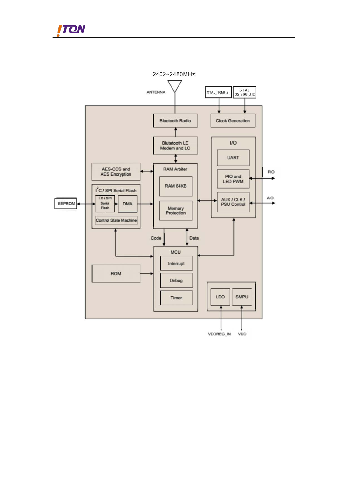
1.5
Functional Block Diagram
Figure 1: Functional Block Diagram
5
AVI1010
Bluetooth 4.1 Module
Pin
Function
I
An
An
I/
Po
I/
I
I/
I/
I/
]
I/
]
I/
I/
I/
I/
Po
I/
]
I/
]
I/
I/
I/
I/
Gr
Gr
Gr
Gr
An
Gr
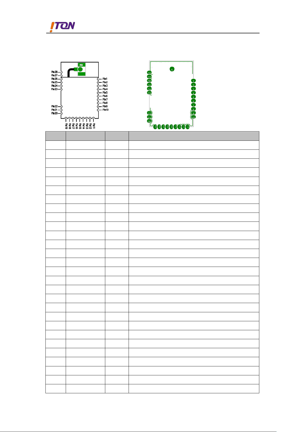
1.6
Physical Description
s Name
1 WAKE
2 XTAL_32K_IN
3 XTAL_32K_OUT
4 I2C_SCL
5 VBATT
6 I2C_SDA
Description
If not used, tie to GND
alog in 32.768KHz installed
alog in 32.768KHz installed
O SPI serial flash installed, or I2C clock Input/output.
wer Power input
O SPI serial flash installed, or I2C data Input/output.
7 SPI_PION
8 PIO[11]
9 PIO[10]
10 PIO[9]
11 SPI_MISO/PIO[8
12 SPI_MOSI/PIO[7
13 SPI_CSB/PIO[6]
14 SPI_CLK/PIO[5]
15 PIO[4]
16 VDD_PADS
17 PIO[3]
18 UART0_RX/PIO[2
19 UART0_TX/PIO[1
20 AIO[0]
21 AIO[1]
22 AIO[2]
23 GND
SPI serial flash installed, or I2C clock Input/output.
O Programmable I/O
O Programmable I/O
O Programmable I/O
O SPI data output or Programmable I/O
O SPI data input or Programmable I/O
O SPI select or Programmable I/O
O SPI clock or Programmable I/O
O Programmable I/O
wer Positive supply for all digital I/O ports
O Programmable I/O
O UART RX or Programmable I/O
O UART TX or Programmable I/O
O Analogue Programmable I/O
O Analogue Programmable I/O
O Analogue Programmable I/O
ound Ground
24 GND
25 GND
26 GND
27 RF
28 GND
ound Ground
ound Ground
ound Ground
tenna External Antenna(reserved)
ound Ground
6

AVI1010
Bluetooth 4.1 Module
Section 2: Supporting Documentations
2.1
The most recent schematic , bill of material ,and layout file are available from the I
TON Technology Corp. Contact your ITON representative for more details.
Reference Schematic
2.2
Layout Considerations
The AVI1010 module is located where the antenna is away from the power supply and any
digital signal traces.The antenna keep-out area which is 5mm around the parameter of the
module region. PCB material and signal traces should not be placed within the antenna
keep-out area to assure optimum antenna performance.
2.3
Recommended Operating Conditions
Operating Condition Symbol Value Unit
Dc supply voltage VBAT 1.8(Min)--3.6(Max) V
I/O supply voltage (VDD_PADS) VI/O 1.2 to 3.6 V
Operating temperature range Topr -30 to +85 ℃
Storage temperature range Tstg -40 to +85 ℃
Figure 2:Recommended Operating Conditions
7

AVI1010
Bluetooth 4.1 Module
2.4
RF Specification
AVI1010 Module contains an integrated balun which provides a single-ended RF TX / RX
IPEX connector. The transmitter has been optimised to deliver power in to a 50Ω load.
And then,the AVI1010 RF Spec base on CSR1010 DataSheet。
Bluetooth Transmitter
■
9dBm RF transmit power with level control from integrated 6-bit DAC over a dynamic
range >25dB
■
No external power amplifier or TX/RX switch required
Bluetooth Receiver
■
-90dBm sensitivity
■
Integrated channel filters
■
Digital demodulator for improved sensitivity and cochannel rejection
■
Fast AGC for enhanced dynamic range
Section 3: Application Diagram
8

AVI1010
Bluetooth 4.1 Module
Section 4: Mechanical Specification
Relative coordinate as below and Unit:mm
9

AVI1010
Bluetooth 4.1 Module
Section 5: Information for Manufacture
10

AVI1010
Bluetooth 4.1 Module
Section 6: Packaging Specifications
For tape and reel packing and labelling see IC Packing and Labelling Specification .
6.1
Figure 6.1 shows the AVI1010 module packing tape orientation.
Tape Orientation
6.2
Figure 6.1 shows the dimensions of the tape for the AVI1010 Module .
Tape Dimensions
Figure 6.1 :Tape Orientation
Figure 6.2: Tape Dimensions
11

AVI1010
Bluetooth 4.1 Module
6.3
Reel Information
Figure 6.3: Reel Information
12

AVI1010
Bluetooth 4.1 Module
Section 7: FCC Statement
This equipment has been tested and found to comply with the limits for a Class B digital device,
pursuant to Part 15 of the FCC Rules. These limits are designed to provide reasonable protection
against harmful interference in a residential installation. This equipment generates, uses and can
radiate radio frequency energy and, if not installed and used in accordance with the instructions,
may cause harmful interference to radio communications. However, there is no guarantee that
interference will not occur in a particular installation. If this equipment does cause harmful
interference to radio or television reception, which can be determined by turning the equipment off
and on, the user is encouraged to try to correct the interference by one of the following measures:
- Reorient or relocate the receiving antenna.
- Increase the separation between the equipment and receiver.
- Connect the equipment into an outlet on a circuit different from that to which the receiver
is connected.
- Consult the dealer or an experienced radio/TV technician for help.
Caution: Any changes or modifications not expressly approved by the party responsible for
compliance could void the user's authority to operate this equipment.
This device complies with Part 15 of the FCC Rules. Operation is subject to the following two
conditions: (1) This device may not cause harmful interference, and (2) this device must accept any
interference received, including interference that may cause undesired operation.
Radiation Exposure Statement
This equipment complies with FCC radiation exposure limits set forth for an uncontrolled
environment. This equipment should be installed and operated with minimum distance 20cm
between the radiator and your body.
This transmitter must not be co-located or operating in conjunction with any other antenna or
transmitter.
This device is intended only for OEM integrators under the following conditions:
1. The antenna must be installed such that 20 cm is maintained between the antenna and users,
and
2. The transmitter module may not be co-located with any other transmitter or antenna,
As long as the three conditions above are met, further transmitter testing will not be required.
However, the OEM integrator is still responsible for testing their end-product for any additional
compliance requirements required with this module installed.
Important Note:
In the event that these conditions cannot be met (for example certain laptop configurations or co-
location with another transmitter), then the FCC authorization is no longer considered valid and the
13

AVI1010
Bluetooth 4.1 Module
Peak Gain (dBi)
2400 – 2483.5
6005ANT
Wire Monopole
IPEX MHF
3.18 dBi
6008ANT
Wire Monopole
IPEX MHF
2.61 dBi
Dipole
RP-SMA
5.50 dBi
AVI1010UFL
Dipole
RP-SMA
5.50 dBi
6005ANT
Wire Monopole
IPEX MHF
3.18 dBi
6008ANT
Wire Monopole
IPEX MHF
2.61 dBi
FCC ID cannot be used on the final product. In these circumstances, the OEM integrator will be
responsible for re-evaluating the end product (including the transmitter) and obtaining a separate
FCC authorization.
End Product Labeling
This transmitter module is authorized only for use in device where the antenna may be installed
such that 20 cm may be maintained between the antenna and users. The final end product must be
labeled in a visible area with the following: Contains FCC ID: 2AFZIAVI1010B.
Manual Information to the E nd User
The OEM integrator has to be aware not to provide information to the end user regarding how to
install or remove this RF module in the user’s manual of the end product which integrates this
module.
The end user manual shall include all required regulatory information/warning as show in this
manual.
Antenna Information
The AVI1010, AVI010UFL and AVI1010NA have designed to pass certification with antenna listed
below; the required antenna impedance is 50 ohms.
Module Model Antenna Model Antenna Type
AVI1010
AVI1010NA
Antenna
Connector
MHz
14

AVI1010
Bluetooth 4.1 Module
Peak Gain (dBi)
2400 – 2483.5
6005ANT
Wire Monopole
IPEX MHF
3.18 dBi
6008ANT
Wire Monopole
IPEX MHF
2.61 dBi
Dipole
RP-SMA
5.50 dBi
AVI1010UFL
Dipole
RP-SMA
5.50 dBi
6005ANT
Wire Monopole
IPEX MHF
3.18 dBi
6008ANT
Wire Monopole
IPEX MHF
2.61 dBi
Section 8: Canada Statement
This device complies with Industry Canada’s license-exempt RSSs. Operation is subject to the
following two conditions:
- This device may not cause interference; and
- This device must accept any interference, including interference that may cause undesired
operation of the device.
Le présentappareilestconforme aux CNR d’Industrie Canada applicables aux appareils radio exempts
de licence. L’exploitationestautorisée aux deux conditions suivantes:
- l’appareil ne doit pas produire de brouillage;
- l’utilisateur de l’appareildoit accepter tout brouillageradioélectriquesubi, mêmesi le
brouillageest susceptible d’encompromettre le fonctionnement.
This radio transmitter (IC: 20544-AVI1010B) has been approved by Industry Canada to operate with
the antenna types listed below with the maximum permissible gain indicated. Antenna types not
included in this list, having a gain greater than the maximum gain indicated for that type, are strictly
prohibited for use with this device.
Le présentémetteur radio (IC: 20544-AVI1010B) aétéapprouvé par Industrie Canada pour
fonctionner avec les types d'antenneénumérés ci-dessous et ayant un gain admissible maximal. Les
types d'antenne non inclusdanscetteliste, etdont le gain estsupérieur au gain maximal indiqué,
sontstrictementinterdits pour l'exploitation de l'émetteur.
Module Model Antenna Model Antenna Type
Antenna
Connector
MHz
AVI1010
AVI1010NA
Radiation Exposure Statement
This equipment complies with Canada radiation exposure limits set forth for an uncontrolled
environment. This equipment should be installed and operated with minimum distance 20cm
between the radiator & your body.
15

AVI1010
Bluetooth 4.1 Module
Déclarationd'exposition aux radiations
Cetéquipementestconforme Canada limitesd'exposition aux radiations dans un environnement non
contrôlé. Cetéquipementdoitêtreinstallé et utilisé à distance minimum de 20cm entre le radiateur et
votre corps.
This device is intended only for OEM integrators under
the following condition:
The transmitter module may not be co-located with any other transmitter or antenna.
As long as the condition above is met, further transmitter test will not be required. However, the
OEM integrator is still responsible for testing their end-product for any additional compliance
requirements required with this module installed.
Cetappareilestconçuuniquement pour les intégrateurs
OEM dans les conditions suivantes:
Le module émetteurpeut ne pas êtrecoïmplanté avec unautreémetteurouantenne.
Tant que les 1 condition ci-dessussontremplies, des essaissupplémentaires sur l'émetteur ne seront
pas nécessaires. Toutefois, l'intégrateur OEM esttoujoursresponsable des essais sur son produit final
pour toutesexigences de conformitésupplémentairesrequis pour ce module installé.
Important Note:
In the event that these conditions cannot be met (for example certain laptop configurations or co-
location with another transmitter), then the Canada authorization is no longer considered valid and
the IC ID cannot be used on the final product. In these circumstances, the OEM integrator will be
responsible for re-evaluating the end product (including the transmitter) and obtaining a separate
Canada authorization.
Note Importante:
Dans le casoùces conditions ne peuventêtresatisfaites (par exemple pour certaines configurations
d'ordinateur portable ou de certaines co-localisation avec un autreémetteur), l'autorisation du
Canada n'est plus considérécommevalide et l'ID IC ne peut pas êtreutilisé sur le produit final.
Danscescirconstances, l'intégrateur OEM sera chargé de réévaluer le produit final (y
comprisl'émetteur) etl'obtentiond'uneautorisationdistincte au Canada.
End Product Labeling
16

AVI1010
Bluetooth 4.1 Module
The final end product must be labeled in a visible area with the following: Contains IC:20544-
AVI1010B.
Plaque signalétique du prod uit f ina l
Le produit final doitêtreétiquetédans un endroit visible avec l'inscriptionsuivante: Contient des IC:
20544-AVI1010B.
Manual Information to the E nd User
The OEM integrator has to be aware not to provide information to the end user regarding how to
install or remove this RF module in the user’s manual of the end product which integrates this
module.
The end user manual shall include all required regulatory information/warning as show in this
manual.
Manuel d'information à l'utilisateur final
L'intégrateur OEM doitêtreconscient de ne pas fournir des informations à l'utilisateur final quant à la
façond'installerou de supprimerce module RF dans le manuel de l'utilisateur du produit final qui
intègrece module.
Le manuel de l'utilisateur final doitincluretoutes les informationsréglementairesrequises et
avertissementscommeindiquédanscemanuel.
17
 Loading...