

on Labs, Inc. 2016.
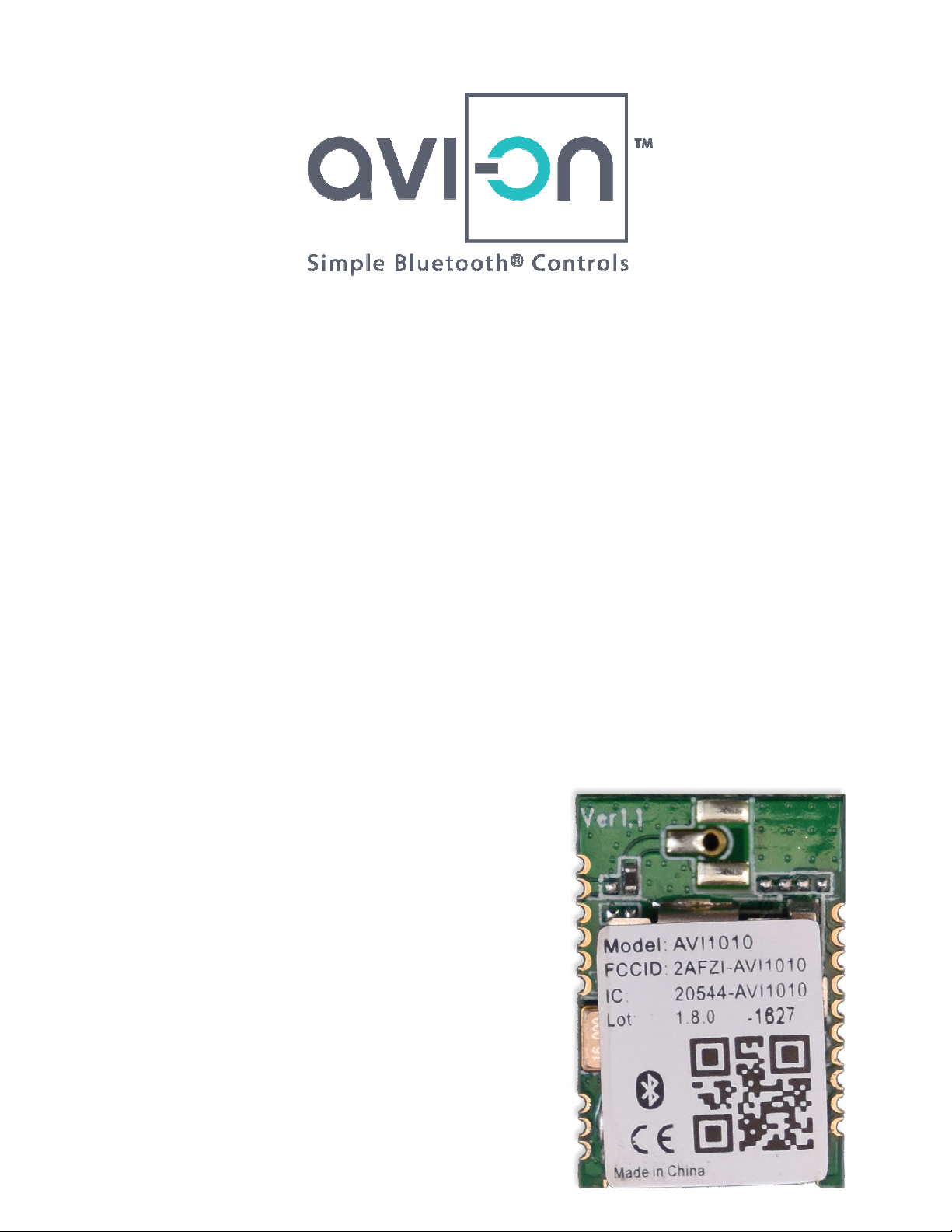
odules
chip solution to controlling all types of lighting
-
Controlling host and radio interfaces, the on
on Bluetooth Mesh Application S
includes the complete receiver and transmitter
functions and integrated antenna or external antenna
AVI1010
onboard
Confidential and Proprietary
More information at
AVI1010
CSR
controller runs both the Bluetooth
chip RF transceiver
Modules
The AVI1010 BLE M
which provide a single-
other devices, whether line
Stack and the Avi-
options.
There are five versions of the
available:
AVI1010INT (includes
are RF modules built on the
connected or battery-powered.
-chip micro-
tack. The on-
BLE modules
antenna; shown at
1010 chipset,
and
right)
Copyright © Avi-
Page 1 of 15
Avi-on.com

on Labs, Inc. 2016.
AVI1010UFL (
includes male U.FL
includes assembled wire antenna
(supports external wire antenna)
supports external antenna through
Confidential and Proprietary
More information at
external antennas
additional
connector for use with
)
AVI1010WIR (
AVI1010NA
AVI1010VIA (
isolation)
)
via; includes
ground via for
Copyright © Avi-
Page 2 of 15
Avi-on.com
on Labs, Inc. 2016.
Platform & Firmware
loaded with standard
prototype builds and testing of lighting and control devices. The complete
package enables manufacturers to design and ship products in less than
using
play
Compatible with UART, I2C, SPI
C operating temp
ternal EEPROM memory provides storage for the Bluetooth software parameter and
Low current consumption: 24 mA @3V (Peak Current)
e integrated ant
Confidential and Proprietary
More information at
firmware suitable for
platform of app
Powered by
temp versions available upon request
Powered by Avi-on™
Modules ship pre-
module-support
six months.
Avi-on Module Features
One step integration
support. Includes plug-and-
ecosystem
Powered by Avi-on™
Powered by Avi-on™
interoperability with the
, and PWM dimming interfaces
app-cloud-
-cloud-firmware-
Avi-on™ product
Up to +85°
In
application parameter
Electrical:
o DC Supply: 1.8V ~3.6V
o
High performanc
; higher
enna (on AVI1010INT)
Copyright © Avi-
Page 3 of 15
Avi-on.com

on Labs, Inc. 2016.
Table of Contents
................................
................................
................................
................................
................................
................................
................................
................................
................................
................................
................................
Confidential and Proprietary
More information at
................................
................................
................................
................................
...............................
................................
................................
................................
................................
................................
...............................
1. Detailed Specifications
2. Regulatory Certifications
3. Default Pin Assignments
4. Pin Assignment
5. System Architecture
6. Mechanicals
7. Pad Layout
8. Antennas ................................
9. Packaging ................................
10. Avi-on Integration Kit
11. Document Record
................................
................................
................................
................................................................
................................................................
................................................................
................................................................
................................
................................
................................
................................................................
............................. 5
........................ 6
.......................... 7
........... 8
10
............... 11
................. 12
.................... 13
................... 13
....................... 14
15
Copyright © Avi-
Page 4 of 15
Avi-on.com
on Labs, Inc. 2016.
fications
•
•
•
Confidential and Proprietary
More information at
2400 to 2483.5 MHz USA/EUROPE/JAPAN
40 (f = 2402 + k*2 MHz, k=0, 1, 2, …39)
If VBATT < 1.8V, power cycle required to
mode (estimated)
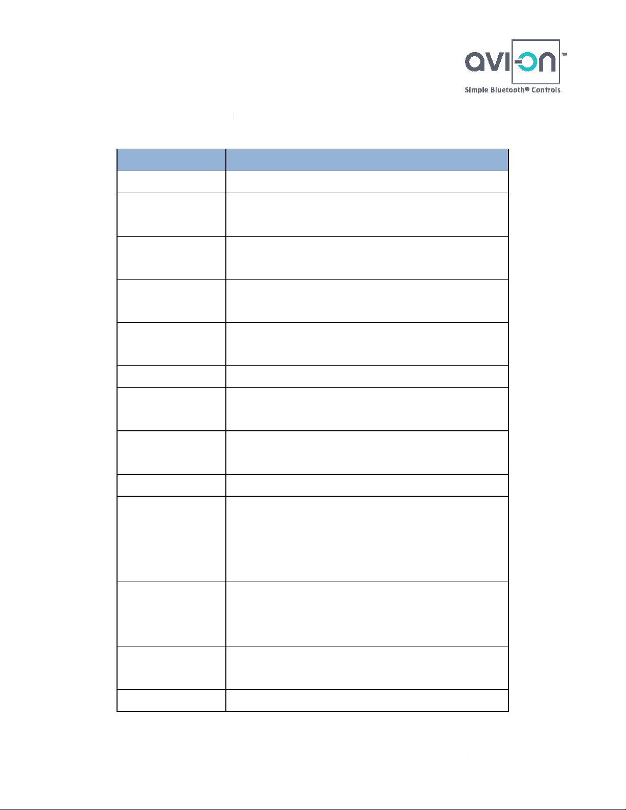
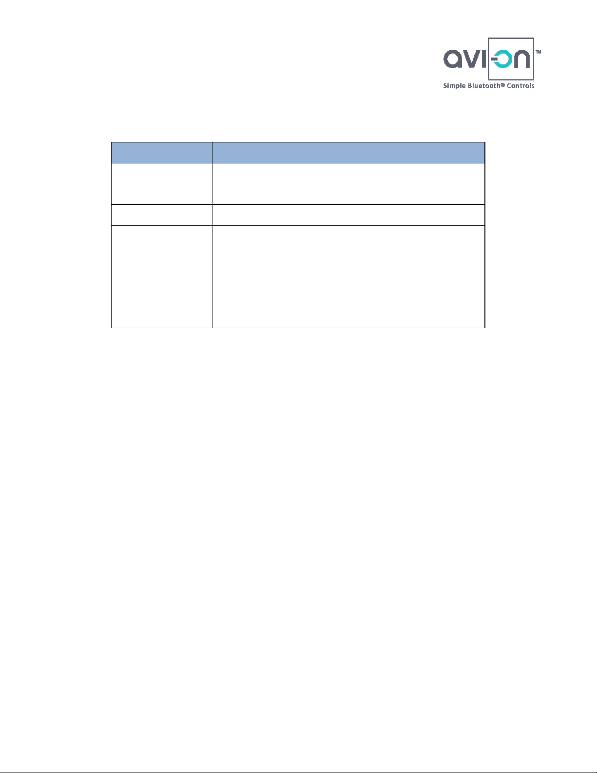
1. Detailed Speci
Characteristic
RF Technology
RF Frequency
Modulation
Schemes
Operating
Frequency
Channel
Numbers
Data Rate
Transmitter
Detailed Description
Frequency Hopping Spread Spectrum
2446.5 to 2483.5 MHz France
0.5 BT, GFSK
Index: 0.28 – 0.35.
2400 ~ 2483.5 MHz ISM band
1 Mbps (Typically)
9 dBm Internal Antenna
Output Power
Receiver
Sensitivity
Antenna Type
Operating
Voltage
Current
Consumption
Size
Operating Temp
9 dBm External Antenna
-93 dBm Typical
Integrated PCB antenna
1.8V ~3.6VDC
Brownout:
o
release device from brownout state
18 mA@3.3V active mode
35 mA@1.8V active Mode
Max. <5uA@3V Sleep
18mm × 12mm × 2.3mm (L x W x H)
Size does not include antenna
-30°C to +85°C
Copyright © Avi-
Page 5 of 15
Avi-on.com
on Labs, Inc. 2016.
Regulatory Certifications
Confidential and Proprietary
More information at
2.
Feature
USA
European
Canada
BQB
Detailed Description
FCC: N/A
•
FCC part 15.247, 15.209, 15B,
•
CE: N/A
•
IC: NA
•
...
•
...
•
DID: NA
•
Qualified Design ID: N/A
•
Copyright © Avi-
Page 6 of 15
Avi-on.com

on Labs, Inc. 2016.
Pin Assignment
Confidential and Proprietary
More information at
Do not connect to
Do not connect to
SPI serial flash installed, or I2C clock
SPI serial flash installed, or I2C data
Selects SPI debug or Programmable I/O,
down: Programmable I/O line,
SPI data output or Programmable I/O
SPI data input or Programmable I/O
SPI select or Programmable I/O
I/O
Positive supply for all digital I/O ports
UART RX or Programmable I/O
3. Default
Pins Name
1 WAKE
2 XTAL_32K_IN
3 XTAL_32K_OUT
4 I2C_SCL
5 VBATT
6 I2C_SDA
s
Function Description
I If not used, leave floating
32.768KHz installed,
Analog in
this Pin.
Analog
In
I/O
Power Power input.
I/O
32.768KHz installed,
this Pin.
Input / output.
Input / output.
7 SPI_PION
8 PIO[11]
9 PIO[10]
10 PIO[9]
11 SPI_MISO/PIO[8]
12 SPI_MOSI/PIO[7]
13 SPI_CSB/PIO[6]
14 SPI_CLK/PIO[5]
15 PIO[4]
16 VDD_PADS
17 PIO[3]
18 UART0_RX/PIO[2]
Pull-High: SPI debug
I
Pull-
default is Pull-down.
I/O Programmable I/O
I/O Programmable I/O
I/O Programmable I/O
I/O
I/O
I/O
I/O SPI clock or Programmable
I/O Programmable I/O
Power
I/O Programmable I/O
I/O
Copyright © Avi-
Page 7 of 15
Avi-on.com

on Labs, Inc. 2016.
19 UART0_TX/PIO[1]
Confidential and Proprietary
More information at
UART TX or Programmable I/O
External Antenna for AVI1010VIA
I/O
20 AIO[0]
21 AIO[1]
22 AIO[2]
23 GND
24 GND
25 GND
26 GND
27 EXT Antenna
28 GND
4. Pin Assignment
I/O Analogue Programmable I/O
I/O Analogue Programmable I/O
I/O Analogue Programmable I/O
Ground Ground
Ground Ground
Ground Ground
Ground Ground
Antenna
Ground Ground
Copyright © Avi-
Page 8 of 15
Avi-on.com

on Labs, Inc. 2016.
Confidential and Proprietary
More information at
Copyright © Avi-
Page 9 of 15
Avi-on.com

on Labs, Inc. 2016.
5. System Architecture
Confidential and Proprietary
More information at
CSR1010
Copyright © Avi-
Page 10 of 15
Avi-on.com

on Labs, Inc. 2016.
6. Mechanicals
Confidential and Proprietary
More information at
Top View:
Bottom View:
Copyright © Avi-
Page 11 of 15
Avi-on.com

on Labs, Inc. 2016.
7. Pad Layout
Confidential and Proprietary
More information at
Copyright © Avi-
Page 12 of 15
Avi-on.com

on Labs, Inc. 2016.
8. Antennas
The AVI1010 series of modules are all functionally the same, with the
ception of antenna design. In
on has pre
for use with the AVI1010, customized for various lighting
c application, Avi
recommendations based on cost and performance qualifications. We
on Certification Program, which:
Benchmarks your product’s RF performance versus other
Provides feedback and recommendations about how to
professional test report
Powered by Avi
The standard shipment of production AVI1010 modules arrive in trays, but Avi
the option for tape and reel packaging
Confidential and Proprietary
More information at
TR), for additional costs.
ex
multiple antenna options. Avi-
applications.
Based on the specifi
also offer the Avi-
•
devices
•
improve
• Provides a
• Enables you to use the
each module configuration, there are
-certified several antennas
-on can provide
-on logo on your products
9. Packaging
contact Avi-on for details.
Copyright © Avi-
(AVI1010XXX-
-on provides
Please
Page 13 of 15
Avi-on.com

on Labs, Inc. 2016.
on Integration Kit
This kit is designed to enable manufacturers to quickly develop lighting and power controls
app
INT module and is loaded with Avi
Board details plus other firmware and dimming protocols available upon request.
Confidential and Proprietary
More information at
daughter board comes
on’s standard PWM firmware.
10. Avi-
using the Powered by Avi-on™
with an Avi-on-
-cloud-firmware platform. The
-
Copyright © Avi-
Page 14 of 15
Avi-on.com

on Labs, Inc. 2016.
11. Document Record
Confidential and Proprietary
More information at
Reason to Change
Created
Initial Review
Date
08/18/2016
08/24/2016
Revision
0.1 Document
0.2
Copyright © Avi-
Page 15 of 15
Avi-on.com

Federal Communication Commission Interference Statement
This equipment has been tested and found to comply with the limits for a Class B
digital device, pursuant to Part 15 of the FCC Rules. These limits are designed to
provide reasonable protection against harmful interference in a residential installation.
This equipment generates, uses and can radiate radio frequency energy and, if not
installed and used in accordance with the instructions, may cause harmful interference
to radio communications. However, there is no guarantee that interference will not
occur in a particular installation. If this equipment does cause harmful interference
to radio or television reception, which can be determined by turning the equipment off
and on, the user is encouraged to try to correct the interference by one of the
following measures:
- Reorient or relocate the receiving antenna.
- Increase the separation between the equipment and receiver.
- Connect the equipment into an outlet on a circuit different from that to which the
receiver is connected.
- Consult the dealer or an experienced radio/TV technician for help.
FCC Caution:
Any changes or modifications not expressly approved by the party responsible for
compliance could void the user's authority to operate this equipment.
This device complies with Part 15 of the FCC Rules. Operation is subject to the
following two conditions:
(1) This device may not cause harmful interference, and
(2) This device must accept any interference received, including interference that may
cause undesired operation.
FCC Radiation Exposure Statement:
This equipment complies with FCC radiation exposure limits set forth for an
uncontrolled environment. This transmitter module must not be co-located or
operating in conjunction with any other antenna or transmitter.
This End equipment should be installed and operated with a minimum distance of 20
centimeters between the radiator and your body.
IMPORTANT NOTE:
In the event that these conditions can not be met (for example certain laptop
configurations or co-location with another transmitter), then the FCC authorization is
no longer considered valid and the FCC ID can not be used on the final product. In
these circumstances, the OEM integrator will be responsible for re-evaluating the end
product (including the transmitter) and obtaining a separate FCC authorization.
End Product Labeling
The final end product must be labeled in a visible area with the following:
“Contains FCC ID: 2AFZI-AVI1010”.

Manual Information to the End User
The OEM integrator has to be aware not to provide information to the end user
regarding how to install or remove this RF module in the user’s manual of the end
product which integrates this module.
Canada Statement
This device complies with Industry Canada’s licence-exempt RSSs. Operation is
subject to the following two conditions: (1) this device may not cause interference,
and (2) this device must accept any interference, including interference that may
cause undesired operation of the device.
Le présent appareil est conforme aux CNR d'Industrie Canada applicables aux
appareils radio exempts de licence. L'exploitation est autorisée aux deux conditions
suivantes : (1) l'appareil ne doit pas produire de brouillage, et (2) l'utilisateur de
l'appareil doit accepter tout brouillage radioélectrique subi, même si le brouillage est
susceptible d'en compromettre le fonctionnement.
Caution Exposure:
This device meets the exemption from the routine evaluation limits in section 2.5 of
RSS102 and users can obtain Canadian information on RF exposure and compliance.
Le dispositif répond à l'exemption des limites d'évaluation de routine dans la section
2.5 de RSS102 et les utilisateurs peuvent obtenir des renseignements canadiens sur
l'exposition aux RF et le respect.
The final end product must be labelled in a visible area with the following:
The Industry Canada certification label of a module shall be clearly visible at all times
when installed in the host device, otherwise the host device must be labelled to
display the Industry Canada certification number of the module, preceded by the
words “Contains transmitter module”, or the word “Contains”, or similar wording
expressing the same meaning, as follows:
Contains transmitter module IC: 20544-AVI1010
This End equipment should be installed and operated with a minimum distance of 20
centimeters between the radiator and your body.
Cet équipement devrait être installé et actionné avec une distance minimum de 20
centimètres entre le radiateur et votre corps.
The end user manual shall include all required regulatory information/warning as
show in this manual.
 Loading...