

Page 1

AI-Audio/Video
Switch System
Installation Manual
Avionics Innovations, Inc.
2450 Montecito Road. Ramona, CA 92065
(760)788-2602 (760)789-7098 Fax
AV3000 Rev NC November 1st2001
Page 2

Avionics Innovations, Inc.
AI-Audio/Video Switch System Installation Manual
Table of Contents
Title Page
Table of Contents-------------------------------------------------------------------------1
General Information----------------------------------------------------------------------2
Unpacking and Inspection---------------------------------------------------------------2
Description---------------------------------------------------------------------------------2
Specifications------------------------------------------------------------------------------3
Warranty Information-------------------------------------------------------------------- 4
Warranty Registration--------------------------------------------------------------------5
Installation Instructions------------------------------------------------------------------6
Instructions for Continued Airworthiness---------------------------------------------7
Contact Information and Technical Assistance---------------------------------------7
Drawing Attachments
AV2008 and AV2009 Connection Drawing-----------------------------------AV2020
A/V Switch System Mounting Plate--------------------------------------------AV2021
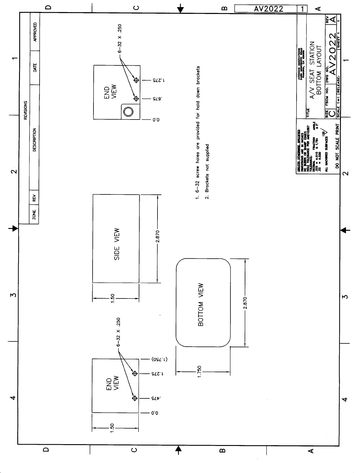
A/V Seat Station Bottom Layout------------------------------------------------AV2022
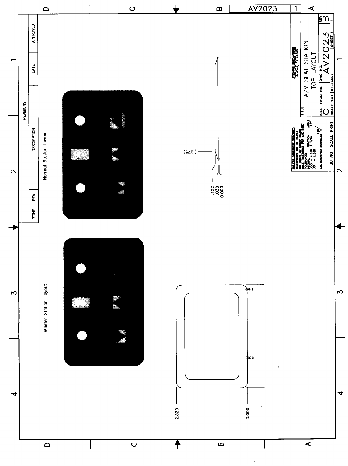
A/V Seat Station Top Layout----------------------------------------------------AV2023
Revision NC 11/01/2001
Page 1
Avionics Innovations, Inc.
Page 3

AI-Audio/Video Switch System Installation Manual
General Information
The purpose of this Installation Manual is to provide information to ensure proper installation
and operation of this product.
Important Note!
It is the responsibility of those desiring to install this item on or within a specific type or
class of certified aircraft to document and obtain approval for an acceptable installation
from the Administrator.
Unpacking and Inspection
Exercise extreme care when unpacking the AI-Audio/Video Switch System. Make a visual
inspection of all units for evidence of damage incurred during shipment. If a claim for damage is
to be made, unit must be returned in the original packaging.
AI-Audio/Video Switch System Description
The AI-Audio/Video Switch System is multiple source switch system that delivers up to 6
sources to as many as 8 different locations. The system has 4 video inputs, 6 audio inputs (Audio
inputs 1 – 4 corespond to Video inputs 1 – 4) and muting capability for a PA sytem.
The system is sold in 4, 6 or 8 station versions. Each of the stations is connected to the main
switch system via a 12 conductor cable utilizing 15 pin Dsub connectors. The individual stations
have the capability of switching between the 6 inputs (depending on how many sources are
connected. If a video monitor is connected the video signal will only be sent if that channel is
selected). All 6 audio inputs can be used with out using the video inputs. Each of the audio
inputs has a adjustment pot that enables the installer to adjust each of the audio inputs for an
equal volume level.
Revision NC 11/01/2001
Page 2
Avionics Innovations, Inc.
Page 4

AI-Audio/Video Switch System Installation Manual
Specifications
Dimensions Switch System 9” Wide x 4.75” Deep x 4” Tall
Seat Station Box 2.87” Wide x 1.75” Deep x 1.5” Tall
Weight Switch System 4 lbs
Seat Station Box 1.5 lbs
Video Input Composite
Audio Input Line Level (2V) Adjustable
Audio Output 4 Volts
Voltage 28 Volts DC
Current Draw 2 AMPS Maximum
Revision NC 11/01/2001
Page 3
Avionics Innovations, Inc.
AI-Audio/Video Switch System Installation Manual
Page 5

WARRANTY INFORMATION
Avionics Innovations warrants the AI-Audio/Video Switch System against material or manufacturing defects for a period
of one year from the date of installation.
Avionics Innovations will, upon receipt of the failed unit, repair or replace the unit at our discretion. Avionics Innovations
will pay UPS Ground shipping charges for warrantied items. Charges for express shipment will be the responsibility of the
sender.
This warranty will be void if the unit has been tampered with or opened by unauthorized personnel.
To validate warranty:
1.) Return the enclosed warranty registration form to Avionics Innovations or complete the online Warranty Application at
www.avionicsinnovations.com
This warranty is not transferable . Any implied warranties expire at the expiration date of this warranty. WE SHALL
NOT BE LIABLE FOR INCIDENTAL OR CONSEQUENTIAL DAMAGES. This warranty does not cover a defect
that has resulted from improper or unreasonable use or maintenance as determined by us. This warranty is void if there is
any attempt to disassemble this product without factory authorization. During the warranty period , the unit must be
returned to Avionics Innovations and, at own option, will be repaired or replaced at no charge. IMPORTANT: Any labor
charges associated with the removal of product or related trouble shooting by any firm other than Avionics Innovations
will not be covered.
Revision NC 11/01/2001
Page 4
Avionics Innovations, Inc.
AI-Audio/Video Switch System Installation Manual
Page 6

WARRANTY REGISTRATION FORM
Model Number’s________________________________________________________________
Serial Number’s_________________________________________________________________
Date of install __________________________________________________________________
Owners name and address_________________________________________________________
______________________________________________________________________________
______________________________________________________________________________
Aircraft make and model__________________________________________________________
______________________________________________________________________________
Registration number _____________________________________________________________
Installing agency________________________________________________________________
______________________________________________________________________________
Comments : ____________________________________________________________________
______________________________________________________________________________
Revision NC 11/01/2001
Page 5
Avionics Innovations, Inc.
AI-Audio/Video Switch System Installation Manual
Page 7

INSTALLATION INSTRUCTIONS
Pre-Installation
Always follow proper avionics installation practices per FAA Advisory Circulars (AC) 43.13-1B or later
FAA approved revision of this document.
Installation
1. Select an appropriate mounting location for the AV2008 (AI-Audio/Video Switch
System). Consider accesability to side adjustment pots, service loops for cables and wire
runs.
2. Mount the AV2008 (AI-Audio/Video Switch System) using (6) AN525-832 bolts, length
TBD and (6) MS21044N08 self locking nuts. Refer to drawing AV2021 (Attached at the
rear of this manual).
3. Select an appropriate mounting location for each of the AV2009 (AI-S/S Controller).
Consider viewing angles, Headset jack protrosions and accessibility.
4. Mount the AV2009 (AI-S/S Controller) using localy manufactured brackets. Attach the
brackets to the AV2009 (AI-S/S Controller) using (4) MS51957 Lenth TBD Screws.
Refer to Drawings AV2022 and AV2023 (attached at the rear of this manual)
5. Route cable and attach to the AV2008 (AI-Audio/Video Switch System) connectors J6 –
J13 (Refer to drawing AV2020).
6. Finish connecting the AV2008 (AI-Audio/Video Switch System) as per drawing AV2020
(attached at the rear of this manual).
7. After all connections are made, adjust the audio inputs using the adjustment pots for an
equal volume level. (Refer to drawing AV2020)
Post Installation
1. Ensure each seat station can select each of the connected sources by pushing the Up and
Down buttons on the AV2009 (AI-S/S Controller). Refer to drawing AV2023 (attached at
the rear of this manual)
2. Using headphones ensure audio is present at each station. Adjust the Volume control and
check for adequate volume range.
3. If a Master station is installed and an external amplifier, ensure that the amplifier can be
turned on and off using the SPEAKERS button on the AV2009).
4. Test and ensure that the installed system does not interfere with any other systems on the
aircraft.
Revision NC 11/01/2001
Page 6
Avionics Innovations, Inc.
AI-Audio/Video Switch System Installation Manual
Page 8

Instructions For Continued Airworthiness
1. The AI-Audio/Video Switch System and the AI-S/S Controller are designed not to require
regular general maintenance.
If the AI-Audio/Video Switch System and the AI-S/S Controller fail to operate, contact Avionics
Innovations, Inc. for assistance.
Avionics Innovations, Inc.
2450 Montecito Road
Ramona, Ca 92065
Phone (760) 788-2602
Website www.avionicsinnovations.com
e-mail support@avionicsinnovations.com
Contacting the Factory for Assistance
Revision NC 11/01/2001
Page 7
Page 9

Page 10

Page 11

Page 12
Page 13
Page 14

 Loading...