

Page 1

PRO64
®
™
Ve r s i o n 3.0.3
User Guide
Page 2

Notice of Rights
All rights reserved. No part of this document may be reproduced or transmitted in any form or by any
means—electronic, mechanical, photocopy, recording, or otherwise—without written permission of
Aviom, Inc.
Trademarks
Aviom, A‑Net, the A‑Net icon, Pro16, Pro64, AllFrame, m‑control, and Virtual Data Cable are trademarks of
Aviom, Inc. All other trademarks are the property of their respective owners.
Aviom products are protected by one or more of the following patents: 7,043,671; 7,301,966; 7,403,828;
7,523,362; 7,526,526; 7,787,580.
© 2012 Aviom, Inc. All rights reserved.
Information subject to change without notice.
Version 3.0.3
Page 3

Table of Contents
Notice of Rights . . . . . . . . . . . . . . . . . . . . . . . . . . . . . . . . . ii
Trademarks . . . . . . . . . . . . . . . . . . . . . . . . . . . . . . . . . . . ii
Welcome . . . . . . . . . . . . . . . . . . . . . . . . . . . . . . . . . . . . . . 1
Firmware Notice . . . . . . . . . . . . . . . . . . . . . . . . . . . . . . . . . 2
Overview . . . . . . . . . . . . . . . . . . . . . . . . . . . . . . . . . . . . . . 3
What’s New in Version 3.0 . . . . . . . . . . . . . . . . . . . . . . . . . . . .4
New in Version 3.0.2 . . . . . . . . . . . . . . . . . . . . . . . . . . . . . . 4
Conventions Used in this Document . . . . . . . . . . . . . . . . . . . . . .5
Installing Pro64 Network Manager . . . . . . . . . . . . . . . . . . . . . 6
Computer Requirements . . . . . . . . . . . . . . . . . . . . . . . . . . . . .6
Start the Installation Process . . . . . . . . . . . . . . . . . . . . . . . . . . .7
Welcome Screens . . . . . . . . . . . . . . . . . . . . . . . . . . . . . . . 7
Software License Agreement . . . . . . . . . . . . . . . . . . . . . . . . 8
Enter User Information . . . . . . . . . . . . . . . . . . . . . . . . . . . . 8
Choose the Installation Location . . . . . . . . . . . . . . . . . . . . . . 9
Install . . . . . . . . . . . . . . . . . . . . . . . . . . . . . . . . . . . . . . . 9
Quitting the Installer . . . . . . . . . . . . . . . . . . . . . . . . . . . . . . . 11
Updating or Removing the Application . . . . . . . . . . . . . . . . . . . 11
What Gets Installed . . . . . . . . . . . . . . . . . . . . . . . . . . . . . . . . 12
Demo Projects . . . . . . . . . . . . . . . . . . . . . . . . . . . . . . . . . . . 12
Pro64 Network Manager Interface . . . . . . . . . . . . . . . . . . . . 13
Pro64 Network Manager Windows . . . . . . . . . . . . . . . . . . . . 14
Workspace . . . . . . . . . . . . . . . . . . . . . . . . . . . . . . . . . . . . . 14
Network Overview . . . . . . . . . . . . . . . . . . . . . . . . . . . . . . . . 15
Device Windows . . . . . . . . . . . . . . . . . . . . . . . . . . . . . . . . . . 16
Scene Manager Window . . . . . . . . . . . . . . . . . . . . . . . . . . . . . . . . . . . 17
Audio Slot Manager Window . . . . . . . . . . . . . . . . . . . . . . . . . . . . . . . 18
Virtual Data Cable Monitor Window . . . . . . . . . . . . . . . . . . . . . 19
Event Log Window . . . . . . . . . . . . . . . . . . . . . . . . . . . . . . . . 19
Firmware Update Window . . . . . . . . . . . . . . . . . . . . . . . . . . . 20
Pr o 64 Ne t w o r k Ma N a g e r Us e r gU i d e
ii i
Page 4

Firmware Updates . . . . . . . . . . . . . . . . . . . . . . . . . . . . . . 21
Software Notice . . . . . . . . . . . . . . . . . . . . . . . . . . . . . . . . . . 21
Update Requirements . . . . . . . . . . . . . . . . . . . . . . . . . . . . . . 21
USB‑to‑RS‑232 Adapters . . . . . . . . . . . . . . . . . . . . . . . . . . 22
Hardware Setup For Firmware Updates . . . . . . . . . . . . . . . . . . 22
Communication Setup For Rack‑Mount I/O Devices . . . . . . . . . 22
Communication Setup For AllFrame I/O Devices . . . . . . . . . . . 24
Communication Setup for the 6416Y2 Card . . . . . . . . . . . . . . 25
Front Panel DIP Switches . . . . . . . . . . . . . . . . . . . . . . . . . . 25
6416Y2 as Control Master . . . . . . . . . . . . . . . . . . . . . . . . . 25
6416Y2 as a Slave Device . . . . . . . . . . . . . . . . . . . . . . . . . . 25
Circuit Board DIP Switches on the 6416Y2 . . . . . . . . . . . . . . . 26
After Updating 6416Y2 Firmware . . . . . . . . . . . . . . . . . . . . . 27
Connecting to the Network for the First Time . . . . . . . . . . . . . . . 28
About COM Ports . . . . . . . . . . . . . . . . . . . . . . . . . . . . . . . 28
Firmware Update Utility Window . . . . . . . . . . . . . . . . . . . . . . .30
Progress Bars . . . . . . . . . . . . . . . . . . . . . . . . . . . . . . . . . . . . 31
If a Firmware Update Fails . . . . . . . . . . . . . . . . . . . . . . . . . 31
Closing the Firmware Update Window. . . . . . . . . . . . . . . . . . . . 32
Firmware Update Window Menus. . . . . . . . . . . . . . . . . . . . . . . 33
File Menu . . . . . . . . . . . . . . . . . . . . . . . . . . . . . . . . . . . . 33
Firmware Report . . . . . . . . . . . . . . . . . . . . . . . . . . . . . . . 33
Update Options Menu. . . . . . . . . . . . . . . . . . . . . . . . . . . . 33
Maintaining a Pro64 Network . . . . . . . . . . . . . . . . . . . . . . . . . 35
Adding Devices to a Network While Online . . . . . . . . . . . . . . . . . 36
Online vs. Offline . . . . . . . . . . . . . . . . . . . . . . . . . . . . . . . 37
Working Online . . . . . . . . . . . . . . . . . . . . . . . . . . . . . . . . . . 37
Working Offline . . . . . . . . . . . . . . . . . . . . . . . . . . . . . . . . . . 37
The Project . . . . . . . . . . . . . . . . . . . . . . . . . . . . . . . . . . . 38
Project Contents . . . . . . . . . . . . . . . . . . . . . . . . . . . . . . . . . 38
Saving a Project . . . . . . . . . . . . . . . . . . . . . . . . . . . . . . . . . . 38
The Project Structure . . . . . . . . . . . . . . . . . . . . . . . . . . . . . . . 39
Scenes vs. Device Presets . . . . . . . . . . . . . . . . . . . . . . . . . . . . 40
Project Compatibility . . . . . . . . . . . . . . . . . . . . . . . . . . . . . . . 41
Transitioning From Online to Offline . . . . . . . . . . . . . . . . . . . . . 42
Transitioning From Offline to Online . . . . . . . . . . . . . . . . . . . . . 42
Going Online With an Unsaved Project Open . . . . . . . . . . . . . 42
Going Online With a Saved Project Open . . . . . . . . . . . . . . . 44
When the Project Has Not Changed . . . . . . . . . . . . . . . . . . . 44
When the Project Has Changed . . . . . . . . . . . . . . . . . . . . . . 45
Pr o 64 Ne t w o r k Ma N a g e r Us e r gU i d e
iv
Page 5

Workspace Features . . . . . . . . . . . . . . . . . . . . . . . . . . . . . 46
Workspace Status Bar . . . . . . . . . . . . . . . . . . . . . . . . . . . . . . 46
Online/Offline Status . . . . . . . . . . . . . . . . . . . . . . . . . . . . 46
Control Master . . . . . . . . . . . . . . . . . . . . . . . . . . . . . . . . 46
Network Mode . . . . . . . . . . . . . . . . . . . . . . . . . . . . . . . . 46
Clock Master . . . . . . . . . . . . . . . . . . . . . . . . . . . . . . . . . . 46
Clock . . . . . . . . . . . . . . . . . . . . . . . . . . . . . . . . . . . . . . . 46
Clock Errors. . . . . . . . . . . . . . . . . . . . . . . . . . . . . . . . . . . 47
Sample Rate . . . . . . . . . . . . . . . . . . . . . . . . . . . . . . . . . . 47
Mute All . . . . . . . . . . . . . . . . . . . . . . . . . . . . . . . . . . . . . 47
Workspace Window Commands . . . . . . . . . . . . . . . . . . . . . . . 48
Workspace Menu Commands . . . . . . . . . . . . . . . . . . . . . . . . . 49
File Menu . . . . . . . . . . . . . . . . . . . . . . . . . . . . . . . . . . . . 49
Network Menu . . . . . . . . . . . . . . . . . . . . . . . . . . . . . . . . 49
Tools Menu . . . . . . . . . . . . . . . . . . . . . . . . . . . . . . . . . . 50
Windows Menu . . . . . . . . . . . . . . . . . . . . . . . . . . . . . . . . 50
About the Open Windows List Contents . . . . . . . . . . . . . . . . 50
Help Menu . . . . . . . . . . . . . . . . . . . . . . . . . . . . . . . . . . . 51
Network Overview Features . . . . . . . . . . . . . . . . . . . . . . . . 52
The Network Overview Interface . . . . . . . . . . . . . . . . . . . . . 53
Changing Column Widths . . . . . . . . . . . . . . . . . . . . . . . . . . . 53
Sorting the Network Overview . . . . . . . . . . . . . . . . . . . . . . . . 53
Status Column . . . . . . . . . . . . . . . . . . . . . . . . . . . . . . . . . . . 53
LED Device Identify Feature . . . . . . . . . . . . . . . . . . . . . . . . 54
Front Panel Lock/Unlock . . . . . . . . . . . . . . . . . . . . . . . . . . 55
Device Column . . . . . . . . . . . . . . . . . . . . . . . . . . . . . . . . . . 56
Numeric ID . . . . . . . . . . . . . . . . . . . . . . . . . . . . . . . . . . . 56
Control Master and Clock Master Indicators . . . . . . . . . . . . . . 57
Filtering the Network Overview . . . . . . . . . . . . . . . . . . . . . . . . 57
The Filter Dialog Box . . . . . . . . . . . . . . . . . . . . . . . . . . . . . 58
Location Column . . . . . . . . . . . . . . . . . . . . . . . . . . . . . . . . . 58
User Labels . . . . . . . . . . . . . . . . . . . . . . . . . . . . . . . . . . . . . 59
Input/Output Slot Range Displays . . . . . . . . . . . . . . . . . . . . . . 60
Filtering by Slot Range . . . . . . . . . . . . . . . . . . . . . . . . . . . 60
Remote Control . . . . . . . . . . . . . . . . . . . . . . . . . . . . . . . . . . 60
Comments Field . . . . . . . . . . . . . . . . . . . . . . . . . . . . . . . . . . 60
Network Overview Menus. . . . . . . . . . . . . . . . . . . . . . . . . . . . 61
File Menu . . . . . . . . . . . . . . . . . . . . . . . . . . . . . . . . . . . . 61
Network Report . . . . . . . . . . . . . . . . . . . . . . . . . . . . . . . 61
Edit Menu. . . . . . . . . . . . . . . . . . . . . . . . . . . . . . . . . . . . 62
View Menu . . . . . . . . . . . . . . . . . . . . . . . . . . . . . . . . . . . 62
Pr o 64 Ne t w o r k Ma N a g e r Us e r gU i d e
v
Page 6

Device Menu . . . . . . . . . . . . . . . . . . . . . . . . . . . . . . . . . 62
Device Window Features . . . . . . . . . . . . . . . . . . . . . . . . . . . 63
Window Views . . . . . . . . . . . . . . . . . . . . . . . . . . . . . . . . . . .64
Fields in the Device Overview . . . . . . . . . . . . . . . . . . . . . . . . . 64
User Label . . . . . . . . . . . . . . . . . . . . . . . . . . . . . . . . . . . 64
Status Bar . . . . . . . . . . . . . . . . . . . . . . . . . . . . . . . . . . . 65
Input/Output Grids . . . . . . . . . . . . . . . . . . . . . . . . . . . . . 65
AllFrame I/O Grids . . . . . . . . . . . . . . . . . . . . . . . . . . . . . . 66
Slot Range . . . . . . . . . . . . . . . . . . . . . . . . . . . . . . . . . . . 67
Activating Channels . . . . . . . . . . . . . . . . . . . . . . . . . . . . 68
Activating All Channels . . . . . . . . . . . . . . . . . . . . . . . . . . . 68
Channel/Slot Conflicts . . . . . . . . . . . . . . . . . . . . . . . . . . . 69
Deactivating Slots . . . . . . . . . . . . . . . . . . . . . . . . . . . . . . 70
Assigning Input Channels to the Matrix . . . . . . . . . . . . . . . . 70
Control Groups . . . . . . . . . . . . . . . . . . . . . . . . . . . . . . . . 71
Device-Specific Features . . . . . . . . . . . . . . . . . . . . . . . . . . . 72
AllFrame . . . . . . . . . . . . . . . . . . . . . . . . . . . . . . . . . . . . . . . 72
AllFrame C4dio Card Support . . . . . . . . . . . . . . . . . . . . . . . 74
C4dio Sample Rate Converters. . . . . . . . . . . . . . . . . . . . . . . 75
AllFrame Standby Options . . . . . . . . . . . . . . . . . . . . . . . . . 77
Standby From the Device Window . . . . . . . . . . . . . . . . . . . . 78
Standby From the F6 Front Panel . . . . . . . . . . . . . . . . . . . . 78
Standby From a Contact Closure . . . . . . . . . . . . . . . . . . . . . 79
Hardware and Software Standby Together. . . . . . . . . . . . . . . 80
Standby and External Clocks. . . . . . . . . . . . . . . . . . . . . . . . 80
AllFrame C4o Output Levels . . . . . . . . . . . . . . . . . . . . . . . . 81
Clearing AllFrame Output Level Settings . . . . . . . . . . . . . . . . 82
6416Y2 A-Net Interface Card . . . . . . . . . . . . . . . . . . . . . . . . . . 83
How DIP Switch #9 Works. . . . . . . . . . . . . . . . . . . . . . . . . . 83
6416Y2 Status Icon . . . . . . . . . . . . . . . . . . . . . . . . . . . . . . 84
m‑control . . . . . . . . . . . . . . . . . . . . . . . . . . . . . . . . . . . 84
VDC Settings . . . . . . . . . . . . . . . . . . . . . . . . . . . . . . . . . . 85
MY8 and MY16 Modes . . . . . . . . . . . . . . . . . . . . . . . . . . . . 86
6416Y2 Output Slots . . . . . . . . . . . . . . . . . . . . . . . . . . . . . 87
6416Y2 Card Stereo Links . . . . . . . . . . . . . . . . . . . . . . . . . 88
Card Configuration Dialog Box . . . . . . . . . . . . . . . . . . . . . . . . 89
Card Mode . . . . . . . . . . . . . . . . . . . . . . . . . . . . . . . . . . . 90
m‑control . . . . . . . . . . . . . . . . . . . . . . . . . . . . . . . . . . . . 90
Pad Mode . . . . . . . . . . . . . . . . . . . . . . . . . . . . . . . . . . . 90
Serial Interface. . . . . . . . . . . . . . . . . . . . . . . . . . . . . . . . . 91
Network Slots to be Remote Controlled. . . . . . . . . . . . . . . . . 91
Pr o 64 Ne t w o r k Ma N a g e r Us e r gU i d e
v i
Page 7

ASI A-Net Systems Interface . . . . . . . . . . . . . . . . . . . . . . . . . . 92
MH10/MH10f Merger Hubs . . . . . . . . . . . . . . . . . . . . . . . . . . . 93
6416dio Digital I/O Module . . . . . . . . . . . . . . . . . . . . . . . . . . . 94
RCI Remote Control Interface. . . . . . . . . . . . . . . . . . . . . . . . . . 95
Matrix Assignments . . . . . . . . . . . . . . . . . . . . . . . . . . . . . . 96
Clearing Matrix Assignments . . . . . . . . . . . . . . . . . . . . . . . 97
Device Window Views . . . . . . . . . . . . . . . . . . . . . . . . . . . . 98
Inputs to Network View . . . . . . . . . . . . . . . . . . . . . . . . . . . . . 98
Stereo Links . . . . . . . . . . . . . . . . . . . . . . . . . . . . . . . . . . 99
Linking/Unlinking Channel Pairs . . . . . . . . . . . . . . . . . . . . . 99
Mic Preamp Channel Settings . . . . . . . . . . . . . . . . . . . . . . . . 100
Clearing Channel Settings . . . . . . . . . . . . . . . . . . . . . . . . .101
Outputs From Network View . . . . . . . . . . . . . . . . . . . . . . . . . 101
Setting an Output Matrix Assignment . . . . . . . . . . . . . . . . . . . 103
Direct Text Entry . . . . . . . . . . . . . . . . . . . . . . . . . . . . . . 104
Matrix Assignments on the ASI . . . . . . . . . . . . . . . . . . . . . . . 105
ASI Outputs . . . . . . . . . . . . . . . . . . . . . . . . . . . . . . . . . 106
ASI Matrix Views . . . . . . . . . . . . . . . . . . . . . . . . . . . . . . 108
Clearing Output Matrix Assignments . . . . . . . . . . . . . . . . . 109
6416Y2 Card and ASI Outputs . . . . . . . . . . . . . . . . . . . . . . .110
The Inputs and Outputs View . . . . . . . . . . . . . . . . . . . . . . . 111
Device Presets. . . . . . . . . . . . . . . . . . . . . . . . . . . . . . . . . . 11 2
The Device Presets View . . . . . . . . . . . . . . . . . . . . . . . . . . . . 11 3
Saving a Device Preset . . . . . . . . . . . . . . . . . . . . . . . . . . .113
Updating a Device Preset . . . . . . . . . . . . . . . . . . . . . . . . .114
Recalling a Device Preset . . . . . . . . . . . . . . . . . . . . . . . . . .114
Clearing a Device Preset . . . . . . . . . . . . . . . . . . . . . . . . . .114
Device Window Menus . . . . . . . . . . . . . . . . . . . . . . . . . . . . 115
File Menu . . . . . . . . . . . . . . . . . . . . . . . . . . . . . . . . . . . . 115
Edit Menu. . . . . . . . . . . . . . . . . . . . . . . . . . . . . . . . . . . . 115
View Menu . . . . . . . . . . . . . . . . . . . . . . . . . . . . . . . . . . .116
Tools Menu. . . . . . . . . . . . . . . . . . . . . . . . . . . . . . . . . . .116
Channel Settings Menu – Input Devices . . . . . . . . . . . . . . . .117
Channel Settings Menu – Output Devices . . . . . . . . . . . . . . . 11 8
Presets Menu . . . . . . . . . . . . . . . . . . . . . . . . . . . . . . . . .11 8
Audio Slot Manager . . . . . . . . . . . . . . . . . . . . . . . . . . . . . . 11 9
Slot Assignments View . . . . . . . . . . . . . . . . . . . . . . . . . . . . 120
Pr o 64 Ne t w o r k Ma N a g e r Us e r gU i d e
v i i
Page 8

Slots and I/O Routing View . . . . . . . . . . . . . . . . . . . . . . . . . . 121
Scene Manager . . . . . . . . . . . . . . . . . . . . . . . . . . . . . . . . . 122
How Scenes Work . . . . . . . . . . . . . . . . . . . . . . . . . . . . . . . . 122
The Scene Manager Window . . . . . . . . . . . . . . . . . . . . . . . . . 123
Scene Manager Features. . . . . . . . . . . . . . . . . . . . . . . . . . . . 124
Number Column . . . . . . . . . . . . . . . . . . . . . . . . . . . . . . .124
Lock Column. . . . . . . . . . . . . . . . . . . . . . . . . . . . . . . . . .12 4
Scene Name Column. . . . . . . . . . . . . . . . . . . . . . . . . . . . .12 4
Scene Valid Column . . . . . . . . . . . . . . . . . . . . . . . . . . . . .124
Scene Notes Column . . . . . . . . . . . . . . . . . . . . . . . . . . . .12 4
Saving a Scene . . . . . . . . . . . . . . . . . . . . . . . . . . . . . . . . . . 12 5
Adding Scene Notes . . . . . . . . . . . . . . . . . . . . . . . . . . . . .125
Renaming a Scene . . . . . . . . . . . . . . . . . . . . . . . . . . . . . .125
Recalling a Scene . . . . . . . . . . . . . . . . . . . . . . . . . . . . . . . . 126
Making Changes to Existing Scenes . . . . . . . . . . . . . . . . . . . . 126
Locking a Scene . . . . . . . . . . . . . . . . . . . . . . . . . . . . . . . . . 126
Locking All Scenes . . . . . . . . . . . . . . . . . . . . . . . . . . . . . .127
Clearing Scenes . . . . . . . . . . . . . . . . . . . . . . . . . . . . . . . . . 127
Scene Compatibility . . . . . . . . . . . . . . . . . . . . . . . . . . . . . . 128
Working Online . . . . . . . . . . . . . . . . . . . . . . . . . . . . . . . .12 8
Working Offline . . . . . . . . . . . . . . . . . . . . . . . . . . . . . . . .128
Validating Scenes . . . . . . . . . . . . . . . . . . . . . . . . . . . . . .129
Scene Manager Menus . . . . . . . . . . . . . . . . . . . . . . . . . . . . 130
File Menu . . . . . . . . . . . . . . . . . . . . . . . . . . . . . . . . . . . .13 0
Edit Menu. . . . . . . . . . . . . . . . . . . . . . . . . . . . . . . . . . . .130
Scene Menu . . . . . . . . . . . . . . . . . . . . . . . . . . . . . . . . . .131
Virtual Data Cable Monitor . . . . . . . . . . . . . . . . . . . . . . . . . 132
The Virtual Data Cable Monitor Window . . . . . . . . . . . . . . . . . 132
VDC Slots . . . . . . . . . . . . . . . . . . . . . . . . . . . . . . . . . . . .133
VDC Type . . . . . . . . . . . . . . . . . . . . . . . . . . . . . . . . . . . .133
RS‑232/422 VDC . . . . . . . . . . . . . . . . . . . . . . . . . . . . . . .133
VDC Source. . . . . . . . . . . . . . . . . . . . . . . . . . . . . . . . . . .13 4
VDC Compatible Devices . . . . . . . . . . . . . . . . . . . . . . . . . .134
VDC Destination . . . . . . . . . . . . . . . . . . . . . . . . . . . . . . .134
Event Log Window . . . . . . . . . . . . . . . . . . . . . . . . . . . . . . 135
Saving Event Log Text . . . . . . . . . . . . . . . . . . . . . . . . . . . . . 135
Troubleshooting . . . . . . . . . . . . . . . . . . . . . . . . . . . . . . . . 136
Pr o 64 Ne t w o r k Ma N a g e r Us e r gU i d e
vi i i
Page 9

Appendix . . . . . . . . . . . . . . . . . . . . . . . . . . . . . . . . . . . . . 138
RS-232 Cables and Pinout . . . . . . . . . . . . . . . . . . . . . . . . . . 138
RS-232 Connections. . . . . . . . . . . . . . . . . . . . . . . . . . . . . . . 138
Wiring a DB9 Crossover Cable . . . . . . . . . . . . . . . . . . . . . . . . 139
Index . . . . . . . . . . . . . . . . . . . . . . . . . . . . . . . . . . . . . . .14 0
soFtware LiCeNse agreeMeNt . . . . . . . . . . . . . . . . . . . . 148
Pr o 64 Ne t w o r k Ma N a g e r Us e r gU i d e
ix
Page 10

We l c o m e
PRO64
®
Network Manager
™
Version 3 of Aviom Pro64® Network Manager™ is a software application designed to manage and
configure Pro64 digital snakes and audio networks from a central location. Pro64 Network Manager
simplifies system installation and device setup while at the same time unlocking flexibility not accessible
from the front panel user interfaces. All Pro64 device are powered by A‑Net®, Aviom’s proprietary audio
distribution and networking technology that is designed specifically for the unique demands of data‑
intensive streaming audio.
Pro64 Network Manager connects to a Pro64 digital snake or audio network via RS‑232 (or USB when
connected to AllFrame Multi‑modular I/O System™ products) and makes use of the network’s built‑in
Managed Mode to simplify tasks related to supporting and configuring Pro64 networks.
All network settings can be monitored, including channel activation and Slot assignment, internal/external
clock source and sample rate, m‑control™, firmware versions and updates, Virtual Data Cables™, and
channel naming.
Pro64 Network Manager helps users track and allocate network resources more efficiently, speeds
configuration of systems and I/O devices, and simplifies troubleshooting and network maintenance.
P No t e : Manual Mode systems are not supported in this version of the application.
Pr o 64 Ne t w o r k Ma N a g e r Us e r gU i d e
1
Page 11

Fi r m W a r e No t i c e
Version 3.0 (and above) of the Pro64 Network Manager application introduces
support for the C4dio card and external clocking options for the AllFrame MultiModular I/O System. All Pro64 devices must be updated to the most recent firmware
(version 5.0 or higher) to be managed and controlled by the Pro64 Network Manager
Version 3 software.
Use Pro64 Network Manager’s built-in Firmware Update utility to update all devices
in the Pro64 network before proceeding.
Pro64 devices with firmware version 4 and earlier (referred to in this document as v2.xx, 3.xx, and 4.xx)
are only compatible with the firmware update utility in the Pro64 Network Manager application until they
are updated to firmware version 5.0 or higher (referred to in this document as v5.xx). Settings on Pro64
devices running older firmware versions (v4.xx and before) cannot be controlled by this version of the
Pro64 Network Manager software.
P No t e : You cannot manage and control a network made up of Pro64 devices whose firmware is a mix of
old and new firmware versions.
Updating firmware requires a direct RS‑232 connection between the PC and the Pro64 network’s Control
Master device. Normally this is accomplished by connecting a null modem DB9 cable between the RS‑2 32
jack on the computer and the Pro64 device. In the case of an F6 Modular I/O Frame (part of the AllFrame
system), a USB connection is required if the F6 is used as the network’s Control Master. Firmware updates
take about 3‑5 minutes per module. (See page 13.)
Computers lacking a serial port connection may require the use of a USB‑to‑RS‑232 adapter to update
non‑AllFrame devices. See page 21 for complete update details.
Pr o 64 Ne t w o r k Ma N a g e r Us e r gU i d e
2
Page 12
ov e r v i e W
The following is an overview of the steps required to start managing and controlling your Pro64 audio
networking products with Pro64 Network Manager.
Download the current version of the Pro64 Network Manager Version software •
installer from the Aviom website (www.Aviom.com).
Install the Pro64 Network Manager application. (See page • 7.)
Connect the Pro64 network to the PC with a DB9 null modem cable, compatible • USB‑
to‑RS‑232 adapter, or USB cable when using AllFrame devices. (See page 21.)
Configure the network’s Control Master so that it can communicate with the software. •
(See page 22.)
Launch Pro64 Network Manager for the first time. (See page • 28.)
Update the firmware in any Pro64 devices that have outdated firmware installed. •
(See page 30.)
When all firmware is updated, start managing the Pro64 network. (See page • 13.)
Explore the features and functions of Pro64 Network Manager including projects •
(page 37), the Network Overview (page 15), Device Windows (page 16), and the Scene
Manager (page 12 2).
After installing the Pro64 Network Manager application you can choose to work offline with the included
demo projects to become familiar with the features of Pro64 Network Manager prior to updating firmware
and working online. See page 12 for additional information.
Pr o 64 Ne t w o r k Ma N a g e r Us e r gU i d e
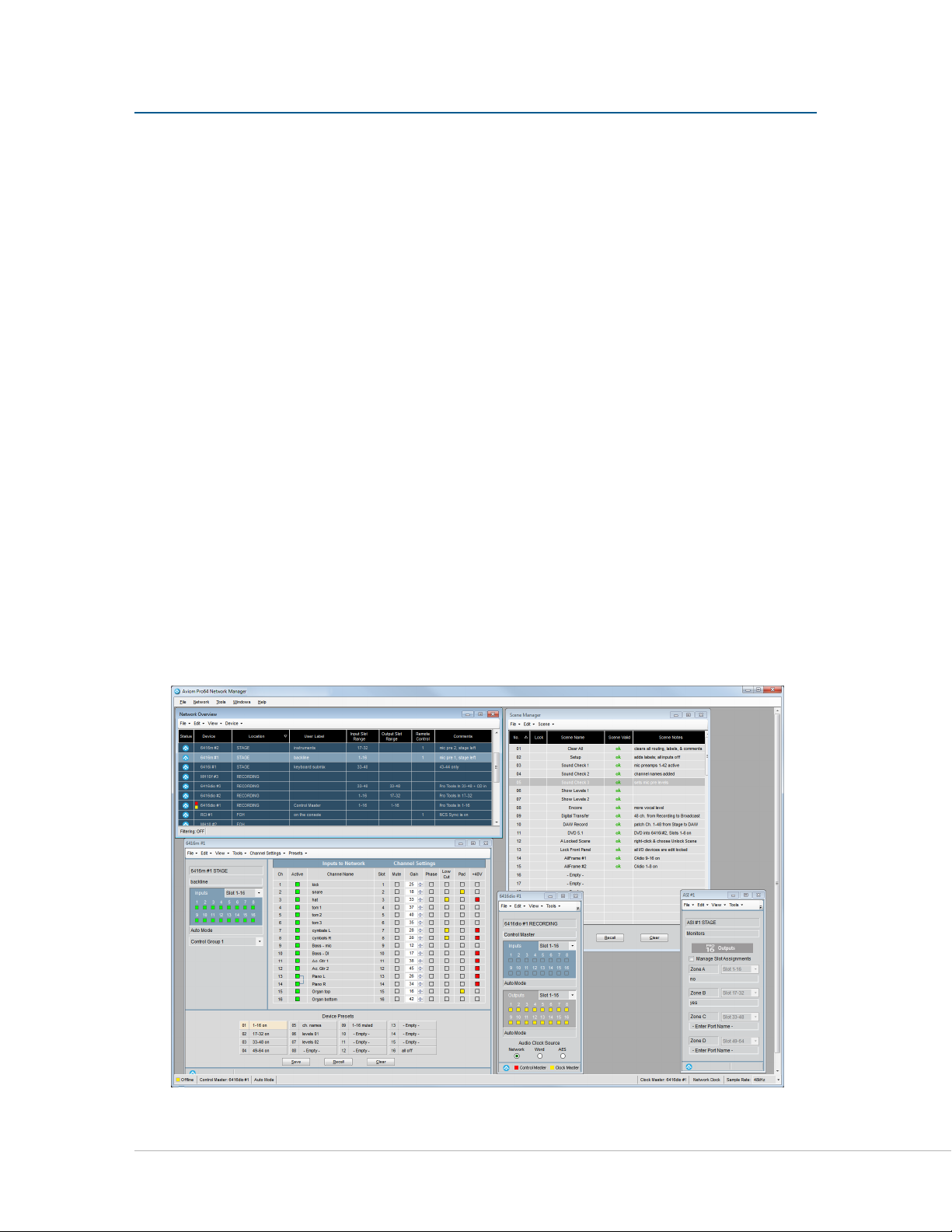
The Pro64 Network Manager workspace
3
Page 13

What’s New in Version 3.0
If your system is already running Version 2 of Pro64 Network Manager, the Version 3 release introduces the
following new features and functionality:
Hardware support for the • C4dio card for the AllFrame—a firmware update to the
AllFrame F6 is required to allow the cards to be recognized. See page 74.
AllFrame devices now support • external clocks (requires at least one C4dio card to be
installed).
External sync via • Word Clock and AES3 clocks are supported when a C4dio card is
installed in an AllFrame.
Optional • sample rate converters (SRC) are available when a C4dio card is installed in
an AllFrame F6 allowing external devices with digital outputs such as CD players to be
connected to a Pro64 network. See page 75.
The AllFrame Device Window has new features that support C4dio cards installed •
in the F6 including Sample Rate Converters on/off switches and Audio Clock Source
menu selection options.
• Standby Mode is now supported for AllFrame devices in the network. See page 77.
Three methods of Standby for AllFrame devices are supported—software based •
using the Device Window in Pro64 Network Manager, from the AllFrame’s dedicated
front panel Standby momentary switch, and hardware‑based using a contact closure
connected to the Euroblock connector on the top panel of the AllFrame. See page 77.
Use the Firmware Update utility (found in the Tools menu of the main workspace) to update the firmware
in your Pro64 devices to take advantage of the new hardware‑related features.
New in Version 3.0.3
In addition to the Version 3.0 features described above, Version 3.0.2 is a maintenance update that
introduces the following:
Device Windows will no longer show multiple warning messages if resource conflicts •
exist when attempting to activate multiple Slots using the Activate All Input Channels
command found in the Channel Settings menu. See page 68.
A new Channel Activation Warning window has been added. •
Network Overview sorting issues have been resolved. •
Pr o 64 Ne t w o r k Ma N a g e r Us e r gU i d e
4
Page 14

Conventions Used in this Document
This document supports Version 3 (and above) of the Aviom Pro64 Network Manger software; it will be
referred to simply as Pro64 Network Manager.
This software revision requires that all Pro64 devices have firmware version 5.00 or higher installed in
order to be used with this version of the software. Version 5 firmware and its variants will be referred to as
v5.xx. Pro64 devices with older firmware versions installed cannot be used online with this version of the
application. They will be referred to as v2.xx, v3.xx, and v4.xx.
An Al l Fr A m e refers to the assembled unit of an F6 Modular I/O Frame plus its installed I/O cards, including
the C4m, C4o, and/or C4dio.
Pr o 64 Ne t w o r k Ma N a g e r Us e r gU i d e
5
Page 15

iN s t a l l i N g Pr o 64 Ne t W o r k ma N a g e r
It is recommended that you quit all running Windows applications before starting the Aviom Pro64
Network Manager installation process.
Check the Aviom website (www.aviom.com) for the latest information about software and firmware
updates and the complete line of Aviom Pro16® and Pro64® products.
Computer Requirements
The minimum computer system requirements for running the Aviom Pro64 Network Manager application
are listed below.
Windows
Intel® or AMD® processor — 1 gigahertz (GHz) or faster •
Intel, AMD, or 100% compatible motherboard & chipset•
Microsoft® Windows® XP with • Service Pack 3 (SP3), or Windows 7
2 gigabyte (GB) RAM (32‑bit systems) or 4 GB RAM (64‑bit systems) •
125 MB of free hard disk space for full installation •
VGA Video (1024 x 768) ‑ 256 colors •
DirectX 9 graphics device with WDDM 1.0 or higher driver•
One available RS‑232 port (or a USB port with a compatible USB‑to‑RS‑232 adapter), or, •
for AllFrame devices, one available USB port
The free Adobe Reader (or equivalent) is required to open the included User Guide from •
the help menu
Microsoft .Net Framework 3.5 •
If your PC does not have the .NET Framework 3.5 components installed, an Internet connection may be
required to download and install these required components from the Microsoft website.
Mac OS
There is no official support for Pro64 Network Manager running on Apple® Mac computers. Experiments
with a Mac running the Windows OS and the third‑party Parallels software have had positive results, but
there is no guarantee of acceptable performance at this time. The system used for the Mac tests included:
Intel®‑based Apple Mac•
• Parallels software (info available from the Apple website)
Mac OS 10.4.6 or higher•
• USB‑to‑RS‑232 converter
Pr o 64 Ne t w o r k Ma N a g e r Us e r gU i d e
6
Page 16
Start the Installation Process
Before installing the software, disconnect the Pro64 network from the PC to avoid any conflicts with
drivers installed by previous versions of the application. Locate the installer file, named “Pro64_Network_
Manager_Installer.exe” and double‑click it to begin the installation process. If an older version of Pro64
Network Manager is already installed on the computer, a dialog box will appear, stating that the currently
installed version must be uninstalled before proceeding. Click Ye s to continue the installation or click No
to abort. Optionally you can choose to uninstall a previous version of Pro64 Network Manager by using the
tools built into the Windows OS Control Panel.
During the install, most screens give the option of navigating back to the previous step to review settings
or make changes before continuing. To do this, click the BA c k button. (To exit the installer at any time prior
to finishing, click the cA N c e l button; no software components will be installed.)
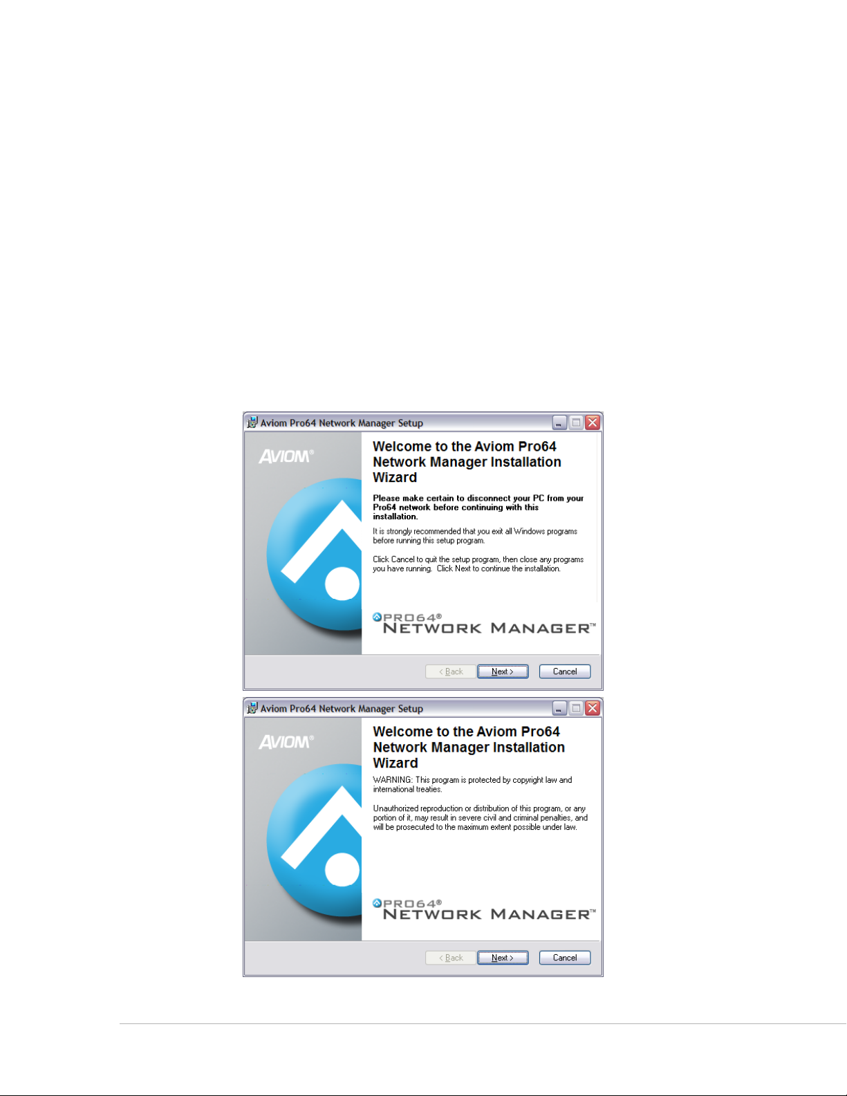
Welcome Screens
When the Welcome screens appear, click Ne x t to continue and install Pro64 Network Manager or click
cA N c e l to exit without running the installer.
Click the Next but ton to continue the installation process.
Pr o 64 Ne t w o r k Ma N a g e r Us e r gU i d e
7
Page 17
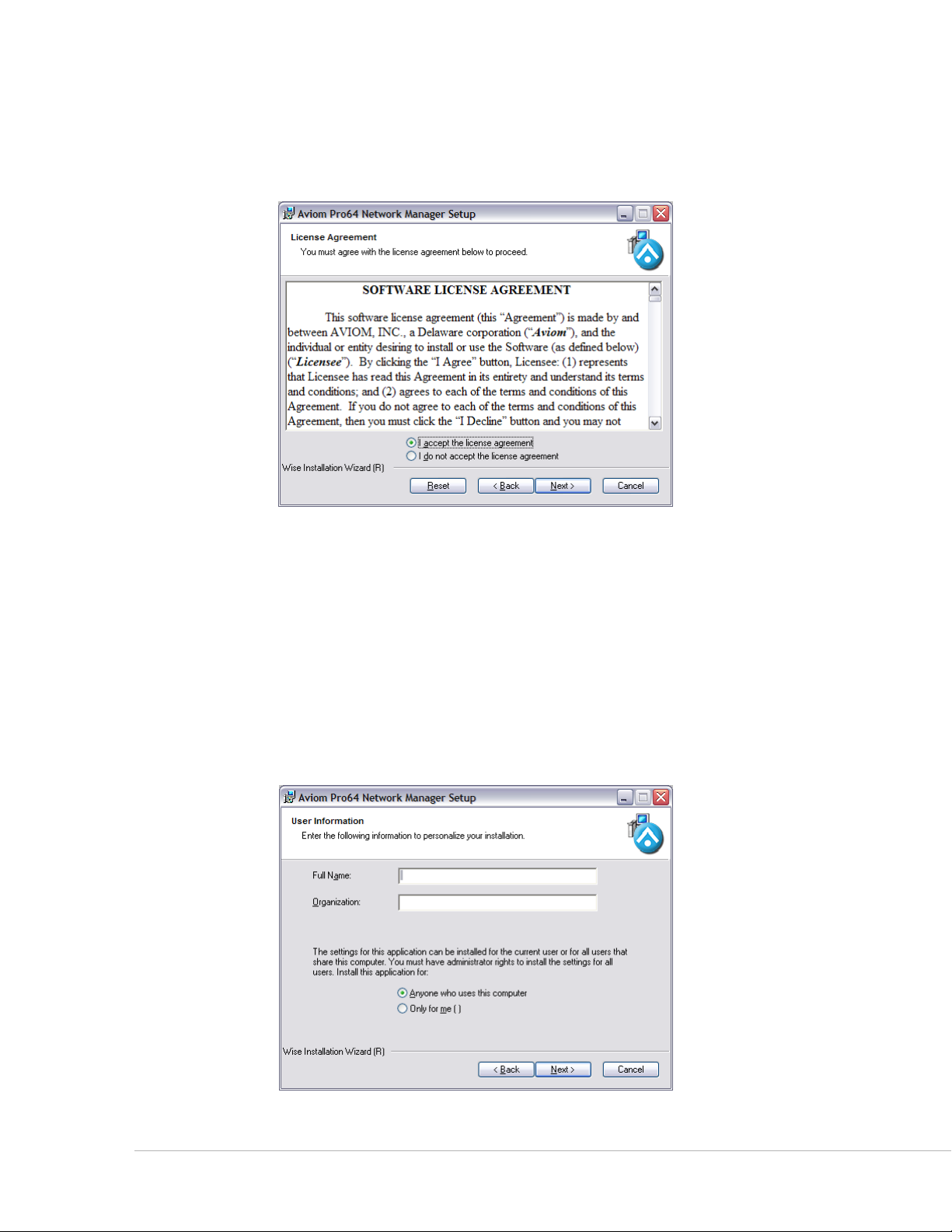
Software License Agreement
When the Software License Agreement page appears, read the agreement completely, click the
I A c c e p t t h e l I c e N s e A g r e e m e N t radio button, and then click the Ne x t button to continue the installation.
The Software License Agreement
If you do not accept the software license agreement the installer will exit without installing Aviom Pro64
Network Manager.
Following the license agreement the current ReadMe document will be displayed.
Enter User Information
You have the option of entering personalized information for the installation, including user and
organization names. When installing on a computer that has multiple users, you have the option of having
the Pro64 Network Manager software accessible to anyone or only to a specific user. Choose the option
that best suits your needs and click its radio button. Click the Ne x t button to continue the installation.
Pr o 64 Ne t w o r k Ma N a g e r Us e r gU i d e
Enter user information
8
Page 18
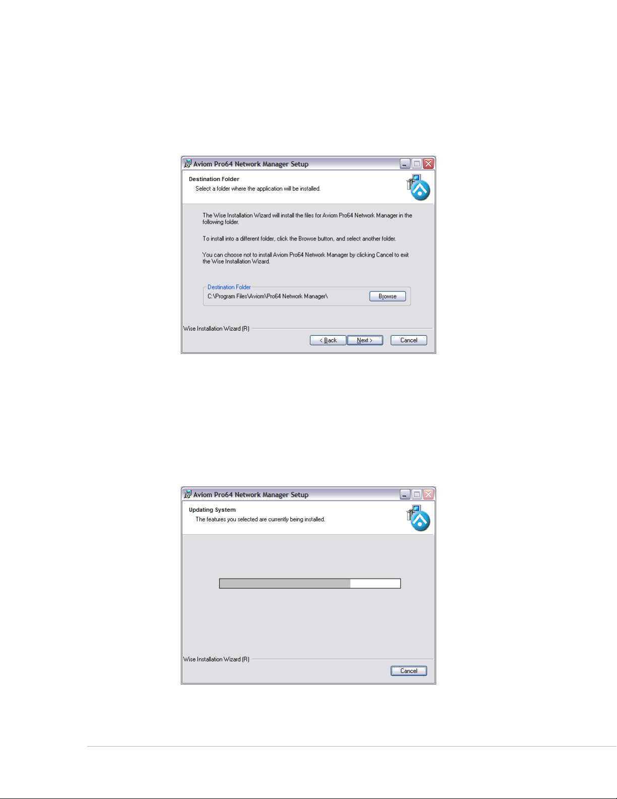
Choose the Installation Location
Select the hard drive and folder location on your computer where the Pro64 Network Manager software
will be installed in the Destination Folder window. To install Pro64 Network Manager using the default
location, simply click the Ne x t button. To install to a different location, click the Br o w s e button and
navigate to and select the desired location. Click Ne x t to continue.
Click Browse... to install Pro64 Network Manager to a folder other than the default location.
Install
At this point, the installer has enough information to install the Pro64 Network Manager application and
its supporting files. On the screen that follows, click Ne x t to begin the installation. Click BA c k to return to
the previous screen to review settings, or click cA N c e l to exit the installer.
A progress bar is displayed during the installation process.
Pr o 64 Ne t w o r k Ma N a g e r Us e r gU i d e
9
Page 19
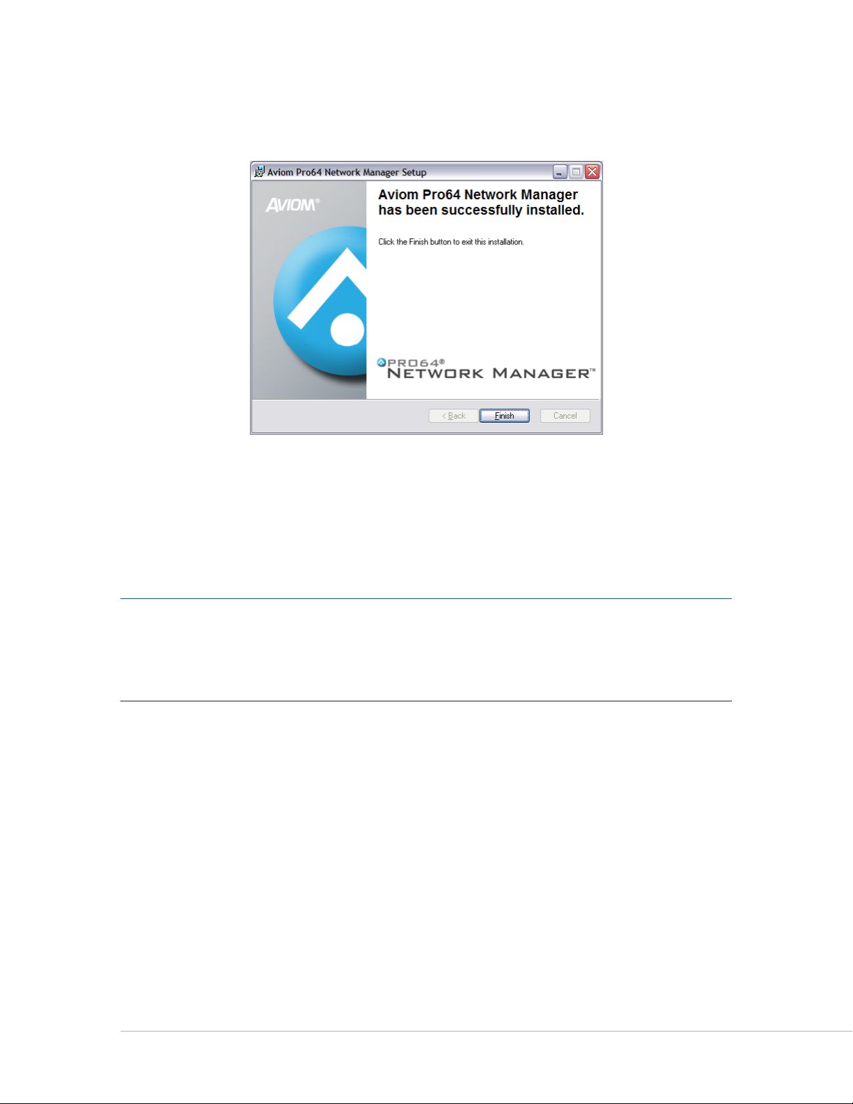
When the install has finished installing the application components, the following screen will be displayed.
Click FI N I s h to complete the installation process.
Click the Finish button to exit the installer.
The installer closes; Pro64 Network Manager is now ready to use (assuming that all required Microsoft
updates and .NET Framework components are correctly installed).
Launch Pro64 Network Manager by double‑clicking its icon or file name in the application folder, or by
selecting pr o 64 Ne t w o r k mA N A g e r from within the Aviom folder in the All Programs section of the PC
Start menu.
P No t e : The Windows XP default location for the installation is
C:\Program Files\Aviom\Pro64 Network Manager\Pro64_Network_Manager.exe
The Windows 7 default location for the installation is
C:\Program Files (x86)\Aviom\Pro64 Network Manager\Pro64_Network_Manager.exe
Pr o 64 Ne t w o r k Ma N a g e r Us e r gU i d e
10
Page 20
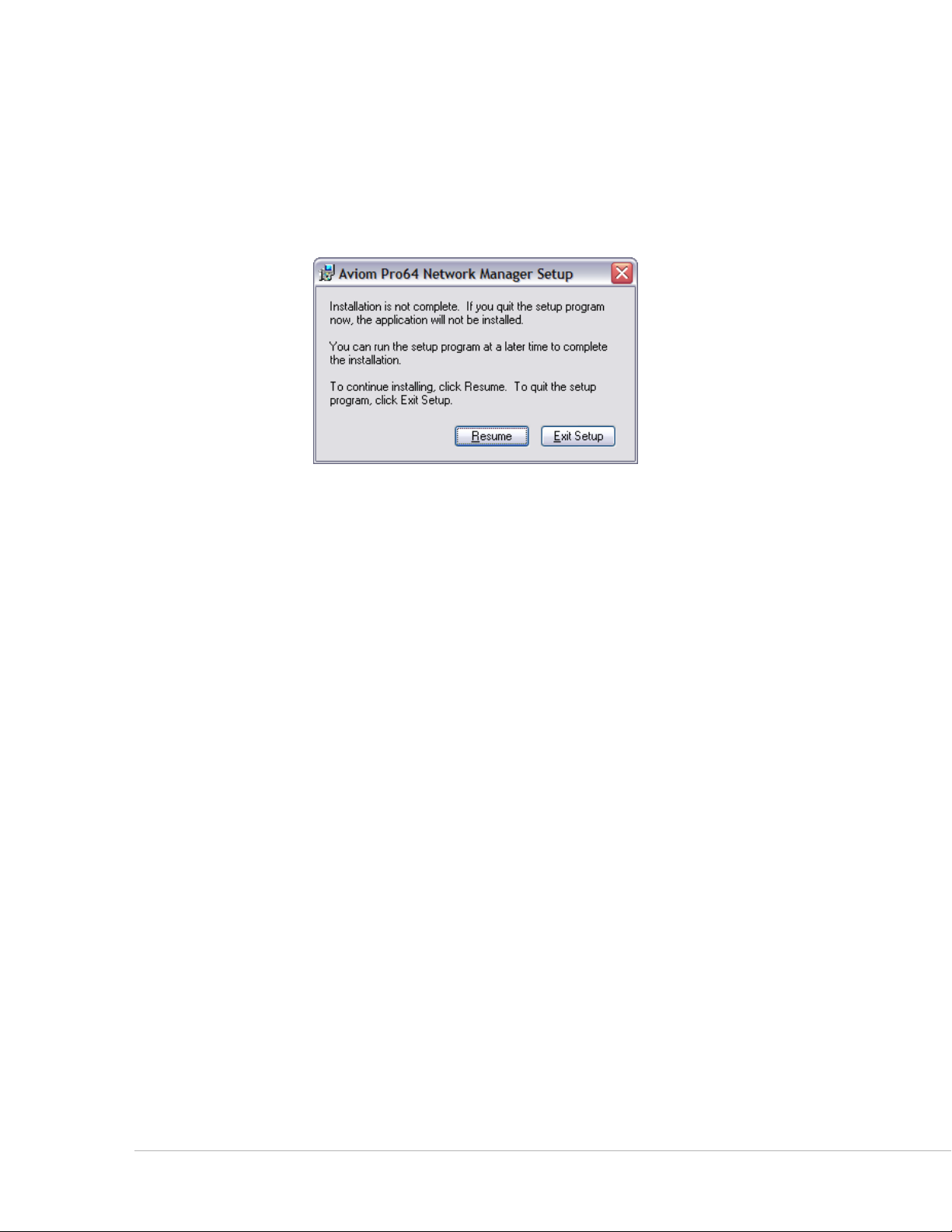
Quitting the Installer
At any time before the installation of Pro64 Network Manager is complete, the user has the option of
exiting the installer. Clicking the cA N c e l button in one of the installer windows will stop the installation
process. In the dialog box that appears after clicking Cancel, choose ex I t se t u p to stop the installer or click
re s u m e to continue the installation process.
Clicking Cancel when running the installer opens this dialog box.
Updating or Removing the Application
When a new version of Pro64 Network Manager is available, the old version of the application will be
removed automatically in the process of installing a new version.
If you want to manually remove Pro64 Network Manager, an uninstall shortcut is placed in the Pro64
Network Manager folder automatically during the initial installation. The utility can be accessed directly
from the Aviom\Pro64 Network Manager folder created in the Programs Menu. Optionally, the application
can be removed by using the standard Windows OS utilities found in the Windows OS Control Panel.
As a precaution, back up any files in the Pro64 Network Manager folder that you wish to save before
proceeding with the uninstall and update procedure. The uninstall utility removes all program files,
product‑specific update files, application icons, log files, registry entries, and text files associated with
Pro64 Network Manager. It does not delete any user‑created files.
Pr o 64 Ne t w o r k Ma N a g e r Us e r gU i d e
11
Page 21

What Gets Installed
Pro64 Network Manager is installed by default into the following folder:
C:\Program Files\Aviom\Pro64 Network Manager (Windows XP) or
C:\Program Files (x86)\Aviom\Pro64 Network Manager (Windows 7).
Within the Pro64 Network Manager folder, which contains the application’s resources, the following folders
will be created.
• Demo Projects – allows you to learn the application and work with each type of
Pro64 device without being connected to a network.
• Device Update – contains the current set of firmware update files (.upd) for all
Pro64 devices
• Documents – documentation, licenses, and ReadMe files
• FTDI USB Drivers – a backup copy of the USB driver installer (required for
AllFrame devices) in case the driver ever needs to be reinstalled
The Update Files folder found within the Device Update folder will contain the most recent firmware
update files for all Pro64 hardware modules, one file per product. Pro64 Network Manager looks in this
folder by default for firmware update files (with extension .upd) for your Pro64 devices.
The Documents folder contains the User Guide and any current ReadMe files. (The free Adobe Reader (or
equivalent) is required to open the included User Guide from the help menu. )
P No t e : Do not rearrange or move any of the files or folders created during the installation.
Demo Projects
The Pro64 Network Manager installation includes multiple demo projects. Use the demo projects to help
you learn the application and its features as well as to explore the functions of Pro64 devices that are not
currently in your network.
Demo Project 1 contains at least one of each Pro64 network device along with sample Scenes and Device
Presets that show the versatility of both the Pro64 network and the Pro64 Network Manager application.
Demo Project 2 contains only AllFrame devices with a variety of I/O card configurations. Demo Project 3 is
smaller, with three AllFrame devices connected to a Yamaha console.
Experiment with recalling presets in the Device Window of a 6416m Mic Input Module, for example, to see
its 16 channel strips change with a single mouse click.
To preserve the original demo project’s settings as you learn the application use the sA v e pr o j e c t As...
command found in the File menu to save a copy of the demo project with a different name before you
begin editing.
P No t e : The demo projects can be opened and edited in offline mode only unless the network you
connect to has the exact same complement of Pro64 devices installed.
Pr o 64 Ne t w o r k Ma N a g e r Us e r gU i d e
12
Page 22
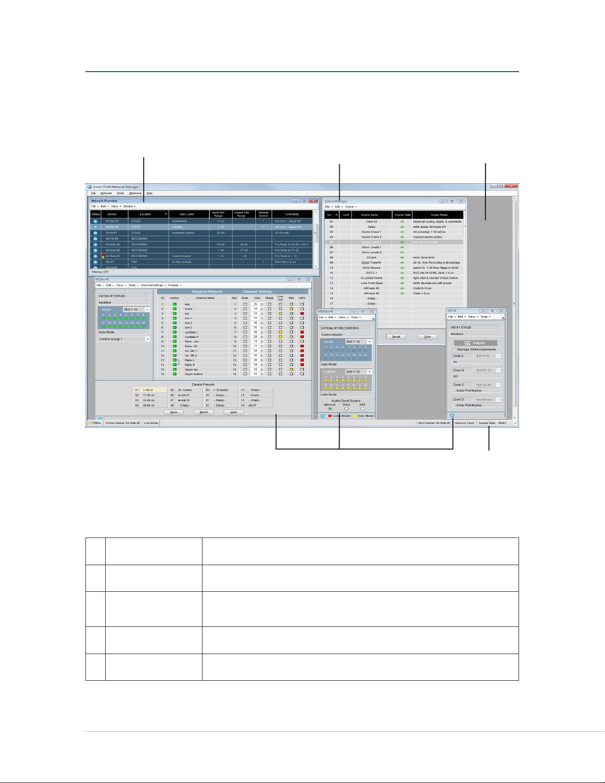
Pr o 64 Ne t W o r k ma N a g e r iN t e r F a c e
The main components of the Pro64 Network Manager user interface are indicated below.
v
w
x
Network Overview Lists all Pro64 devices and their properties
Scene Window Save and recall up to 99 network scenes
v
Main Workspace
w
Device Windows Displays specific information for each type of Pro64 device
x
Status Bar Displays online/offline status, network mode, sample rate, and clock info
y
Pr o 64 Ne t w o r k Ma N a g e r Us e r gU i d e
Holds all other application windows such as the Network Overview and
Device Windows
y
13
Page 23

Pr o 64 Ne t W o r k ma N a g e r Wi N d o W s
The Pro64 Network Manager application consists of the following components:
Application • Workspace
• Network Overview
Individual • Device Windows
• Scene Manager Window
• Virtual Data Cable Manager Window
• Audio Slot Manager Window
• Event Log Window
• Firmware Update Window
The following section presents a brief overview of these components and the windows that make up the
Pro64 Network Manager application. Each window, along with its features, menu items, and functions is
described in detail in the sections that follow this overview.
Workspace
The Workspace is the general application window that holds all other windows such as the Network
Overview and Device Windows. The workspace cannot be closed while the Pro64 Network Manager
application is running. The workspace can be sized and positioned on the PC desktop by the user. Closing
the main workspace window exits the application.
The empty main workspace before loading a project
The workspace will be blank when there is no project loaded or when the application is not connected
online to a Pro64 network. See page 46 for additional information.
Pr o 64 Ne t w o r k Ma N a g e r Us e r gU i d e
14
Page 24
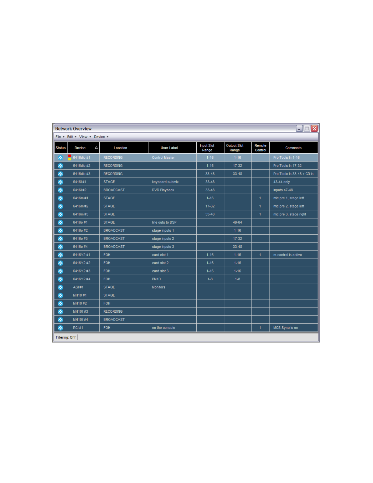
Network Overview
The Network Overview shows a list of all Pro64 devices in the current network and project along with
Slot range properties and user‑defined text fields. The Network Overview can be opened/closed and
repositioned in the workspace, or resized as needed while the application is running. The information
displayed in the Network Overview can be sorted by column type.
The Network Overview has a local menu bar containing functions that allow you to print a network report,
filter devices and/or Slot ranges from the current view, etc. A Status Bar runs along the bottom edge of this
window that displays information specific to the Network Overview such as filtering.
The Network Overview shows the entire network conguration at a glance.
Use the keyboard shortcut ct r l +1 to open the Network Overview; it can also be opened by choosing
Ne t w o r k ov e r v I e w from the Windows menu of the main workspace. See page 52 for additional
information.
Pr o 64 Ne t w o r k Ma N a g e r Us e r gU i d e
15
Page 25
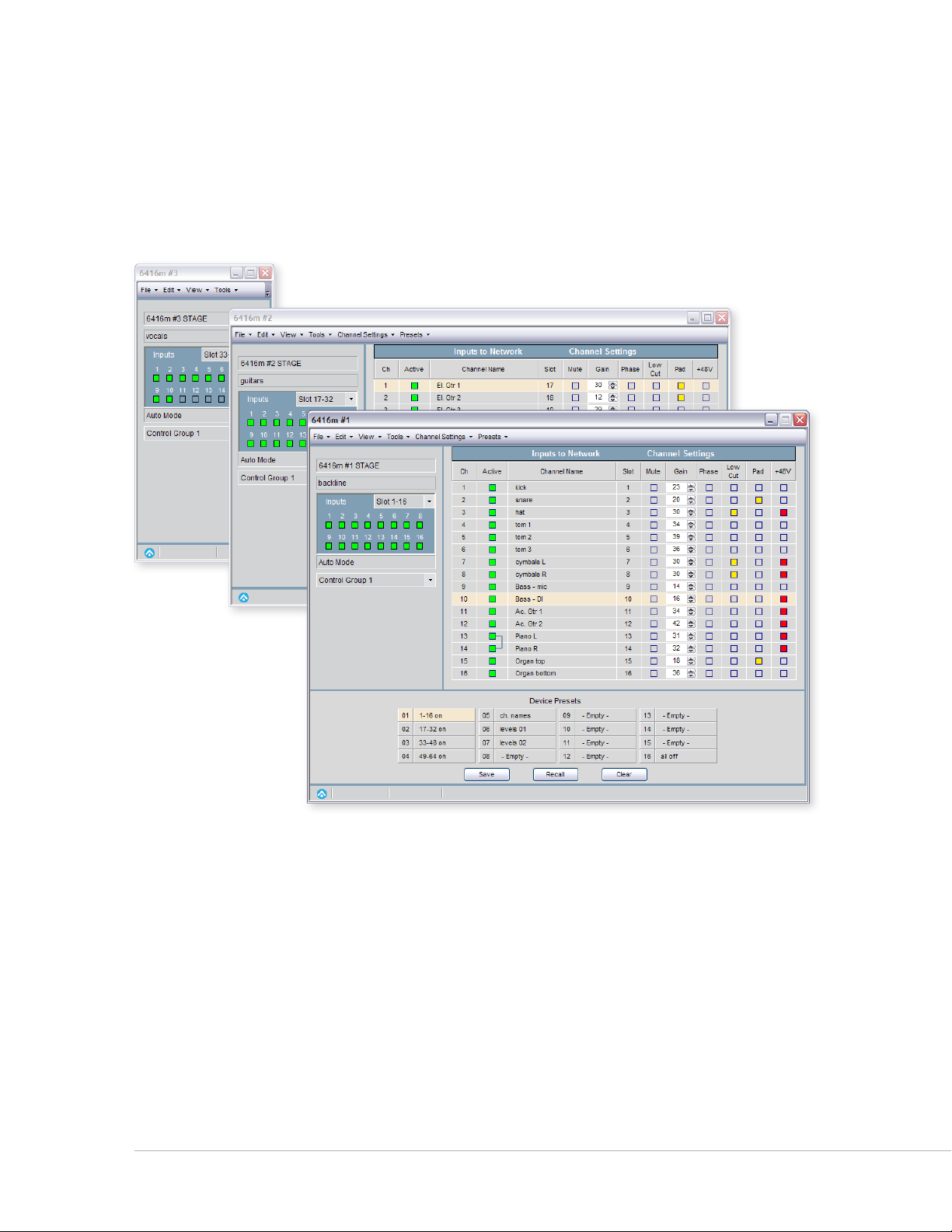
Device Windows
A Device Window displays specific information for each type of Pro64 device (6416m, 6416dio, AllFrame,
MH10, ASI, etc.). Device Windows are used to manage and edit a device’s settings such as Slot range, routing,
channel activation, input channel names, as well as providing an interface for saving and recalling up to 16
device presets. Each Device Window contains multiple views designed specifically for that device.
The Device Window oers multiple views of a Pro64 device’s settings.
Multiple Device Windows may be open within the workspace, but only one view for a given Pro64 device
may be open at a time. Device Windows have their own local menu bars containing items designed to
control settings unique to that device; you can also print a report for each device. The Device Windows can
be opened, closed, and repositioned in the workspace as needed.
Double‑clicking a single device row in the Network Overview opens its Device Window. With a device
highlighted in the Network Overview, using the keyboard shortcut ct r l +D also opens its Device Window.
See page 63 for additional information.
Pr o 64 Ne t w o r k Ma N a g e r Us e r gU i d e
16
Page 26
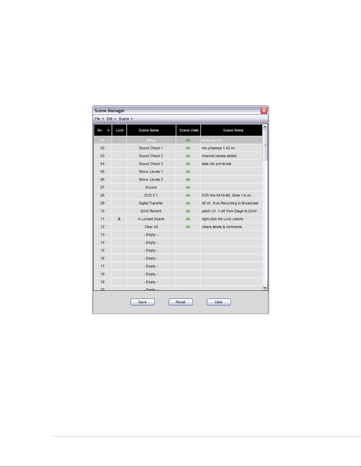
Scene Manager Window
A Scene saves the configuration of everything in the Pro64 network—channel on/off settings, routing,
input channel names, and so on. The Scene Manager Window allows the user to save, recall, name, and
manage up to 99 Scenes stored within the current project. Scenes allow the user to reconfigure an entire
Pro64 audio network from a central location, making setup changes for multiple devices for any type of
production easy to manage.
The Scene Manager allows a user to create, save, and recall scenes that are part of a project.
Use the keyboard shortcut ct r l +2 to open the Scene Manager. The window can also be opened by
choosing sc e N e mA N A g e r from the Windows menu of the main workspace. See page 12 2 for additional
information about Scenes.
Pr o 64 Ne t w o r k Ma N a g e r Us e r gU i d e
17
Page 27
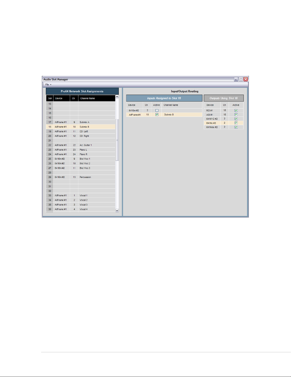
Audio Slot Manager Window
The Audio Slot Manager allow the user to view the I/O routings for an entire Pro64 network from a central
location. Each network Slot can be examined individually, with the window displaying lists of all devices
that have assignments to the same Slot. Activation of input and/or output devices can also be managed
from this window.
The Audio Slot Manager provides an overview of the routing of all network Slots in a project.
Use the keyboard shortcut ct r l +4 to open the Audio Slot Manager. The window can also be opened by
choosing Au D I o sl o t mA N A g e r from the Windows menu of the main workspace. See page 119 for additional
information.
Pr o 64 Ne t w o r k Ma N a g e r Us e r gU i d e
18
Page 28
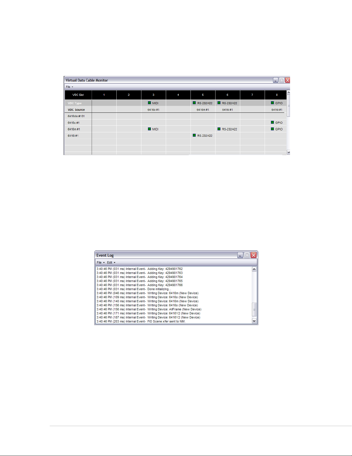
Virtual Data Cable Monitor Window
The Virtual Data Cable™ (VDC) Monitor window is used for viewing the routing of the 14 Virtual Data Cable
Slots available in the network.
The VDC window displays the status of the 14 Virtual Data Cable Slots.
To open the Virtual Data Cable Monitor use the keyboard shortcut ct r l +3 or choose vI r t u A l DA t A cA B l e
mo N I t o r from the Windows menu of the workspace. See page 13 2 for additional VDC information.
Event Log Window
The Event Log shows text relating to network activity, errors, etc. Its contents can be saved to disk and
portions of the log text can be copied, pasted, etc. as needed. The Event Log captures up to 256 lines of
messages to the computer’s on‑board RAM.
The Event Log can be positioned anywhere on screen as needed.
In the main workspace open the Event Log by choosing ev e N t lo g from the Windows menu or by using
the keyboard shortcut ct r l +5. The Event Log can be opened/closed, repositioned, or resized on screen as
needed.
Text created by the Event Log must be saved by copying and pasting into a new desktop document if any
portions of it need to be retained. See page 135 for additional information.
Pr o 64 Ne t w o r k Ma N a g e r Us e r gU i d e
19
Page 29
Firmware Update Window
The Firmware Update utility is accessed from the Tools menu in the main workspace when the application
is online and connected to a Pro64 network. It shows a list of all Pro64 devices in the current network and
allows their firmware to be updated.
Firmware Update window and progress bars
The Firmware Update utility can also be used to roll back the firmware of any Pro64 device to any previous
firmware version. See page 21 for additional information.
Pr o 64 Ne t w o r k Ma N a g e r Us e r gU i d e
20
Page 30

Fi r m W a r e UP d a t e s
Firmware is the embedded software that resides in each Pro64 device. Updating firmware can be done
one device at a time or in a batch, as would happen when connecting a version 4.xx or prior network to
Pro64 Network Manager Version 3 for the first time. All Pro64 devices in a network should be updated to
the most recent firmware to avoid compatibility issues.
The Firmware Update utility is contained within Pro64 Network Manager and runs in a separate window.
During a firmware update (and as long as the Firmware Update window is open) you cannot edit or make
any changes in the other windows of the Pro64 Network Manager application.
Software Notice
Pro64 Network Manager’s Firmware Update utility replaces the Pro64 Update Tool software previously
released for firmware management. The Pro64 Update Tool software is no longer supported.
If you need to maintain a group of older Pro64 device’s firmware but do not need to control and manage
your Pro64 network, you can still do firmware updates using Pro64 Network Manager without updating
to v5.xx firmware. You will not have access to any of the other Pro64 Network Manager functionality until
those devices are updated to v5.xx firmware.
P No t e : Version 5.xx firmware is required to run Pro64 Network Manager Version 3 online. .
Update Requirements
For rack‑mount I/O devices, such as the 6416m Mic Input Module, updating firmware requires a direct
RS ‑232 connection between the computer and the Pro64 network’s Control Master device. Normally this is
accomplished by connecting a null modem DB9 cable between the RS ‑232 jacks on the computer and the
Pro64 device. Firmware updates take 3‑5 minutes per device to complete.
Computers lacking an integrated RS‑232 COM port connection may require the use of a USB‑to‑RS‑232
adapter. The adapter (sometimes called a USB‑to‑Serial adapter) operates as a bridge between a USB port
and a standard RS‑232 Serial COM port.
If an AllFrame device, such as the F6 Modular I/O Frame is used as the network’s Control Master, a USB
connection is required between the F6 and the computer. See page 24.
The Appendix section of this document contains wiring and pinout information for RS‑232 and null modem
cables. See page 13 8.
Pr o 64 Ne t w o r k Ma N a g e r Us e r gU i d e
21
Page 31

USB-to-RS-232 Adapters
1 2 3 4 5 6 7 8 9 10
ON
The following USB‑to‑RS‑232 Adapters have been tested by Aviom and found to work with the Pro64
Network Manager application:
Keyspan • USB High Speed Serial Adapter (Model USA‑19HS) Run their utility
software to determine the COM port that is in use.
Gigaware USB-A to Serial Cable• (Model 26‑949) Easy to configure; readily available
from Radio Shack© stores.
IOGEAR USB to Serial Converter Cable• (Model GUC232A) Must configure the
device’s baud rate and get its COM port info from within the Ports section of the
Windows OS Device Manager; not well documented. Identifies itself as the ATEN USB
to Serial Bridge.
CablesToGo 13in Port Authority USB Serial DB9 Cable• (Model 26886) Must
configure the device’s baud rate and get its COM port info from within the Ports
section of Windows OS Device Manager; not well documented.
Hardware Setup For Firmware Updates
Follow the steps below to set up the computer and the Pro64 network prior to launching the Pro64
Network Manager application for the first time. If your network uses a 6416Y2 A-Net Interface Card* or
AllFrame F6 as the Control Master, see the sections that follow for specific information about setting up
these devices.
Communication Setup For Rack-Mount I/O Devices
To set up Pro64 rack‑mount I/O devices such as the 6416m, 6416dio, and 6416o for updating:
• Connect an RS‑232 serial cable (null modem) or properly configured USB‑to‑RS‑232
adapter between the PC and the Pro64 network’s Control Master device. You may
need to configure the PC’s COM port settings for some USB‑to‑RS‑232 converters.
Configure the Control Master device to communicate at 57.6k • baud with 8 data bits,
one stop bit, and no parity using the DIP switches found in the RS‑232 section of the
device’s Virtual Data Cable™ (VDC) section of the rear panel as seen in the example
below **.
57.6k baud DIP switch settings (DIP switch handles are black)
• Disable any RS‑232 or RS‑422 Virtual Data Cables that are in use on the Control Master.
On the front panel of the • Control Master device, press the mA N A g e D button followed
by the eN t e r button. The Managed button will light yellow.
At this point you are ready launch the Pro64 Network Manager application.•
Pr o 64 Ne t w o r k Ma N a g e r Us e r gU i d e
22
Page 32

* If you are using the 6416Y2 A‑Net Interface Card as the Control Master device, you can simplify the
VIRTUAL DATA CABLE PORTS
IN
OUT
RS-
RESERVED
CONTROL MASTER
–8
IN OUT
ON
RS-
Mic Input Module
B
A
firmware update process by switching the Control Master function to a rack‑mount Pro64 I/O device or
AllFrame device temporarily.
** The 6416dio Digital I/O Module has a 12‑position DIP switch on its rear panel; DIP switch #10 is still
used to set the device as the Control Master for the network. Leave DIP switches 11 and 12 in the down
position. (DIP switch #12 selects between RS‑232 and RS‑422 communication.)
P No t e : The DIP switch settings described above must be used any time the firmware is updated or rolled
back on a rack‑mount I/O device used as the network’s Control Master. Leave the DIP switches set
as shown in the diagram above to simplify future updates.
Connect the PC to the Control Master device with an RS-232 cable.
Pr o 64 Ne t w o r k Ma N a g e r Us e r gU i d e
23
Page 33

Communication Setup For AllFrame I/O Devices
1 2 3 4
C4o
1 2 3 4
C4o
D
E
F
Modular I/O Frame
F6
CONTROL
MASTER
STANDBY
AllFrame Modular I/O System devices such as the F6 Modular I/O Frame do not require the user to set a
baud rate prior to starting firmware updates. When an AllFrame device such F6 is the Pro64 network’s
Control Master follow these steps to set up the device for firmware updates:
Remove the • control panel cover on the front of the F6.
Make sure that the Control Master switch is in the up position. •
Connect a • USB cable to the Type‑B USB port on the F6.
Connect the other end of the USB cable to the PC. •
Launch the Pro64 Network Manager application. •
Pr o 64 Ne t w o r k Ma N a g e r Us e r gU i d e
Connect the F6 to a PC using a USB cable when the F6 is the Control Master.
24
Page 34

Communication Setup for the 6416Y2 Card
RS–232/422
STEREO LINK
6416
Y
2
B A
ON
CTLCLKAUTO ERR
1 2 3 4 5 6 7 8 9 10 11 12
RS–232/422
STEREO LINK
6416
Y
2
B A
ON
CTLCLKAUTO ERR
1 2 3 4 5 6 7 8 9 10 11 12
This section details the card settings required for updating firmware; they must be made on all the 6416Y2
cards in a network before being installed in a Yamaha host device and running Pro64 Network Manager for
the first time. DIP switch settings are slightly different if the 6416Y2 card is the network’s Control Master
versus if it is a slave card.
Front Panel DIP Switches
On the front panel of the 6416Y2 card, the system lock (DIP switch #9) and m‑control (DIP switch #10)
functions need to be disabled during a firmware update. To do this set DIP switch #9 and #10 up—this is
the ‘off’ position for switches in this DIP switch block. If the network contains multiple 6416Y2 cards, be
sure to disable m‑control on each card before starting the firmware update process. Choose the front‑
panel option that suits your application (the card is either the Control Master or a slave device), then move
on to setting up the card’s other DIP switches for the firmware update by following the steps in the section
that follows.
6416Y2 as Control Master
Front panel settings for a card set as Control Master; switch #12 down (DIP switch handles are black)
6416Y2 as a Slave Device
Front panel settings for a non-Control Master (slave) card; all DIP switches in the up position
Pr o 64 Ne t w o r k Ma N a g e r Us e r gU i d e
25
Page 35

Circuit Board DIP Switches on the 6416Y2
ON
ON
ON
ON
ON
ON
SW7
SW8
SW3
SW9
SW4
SW1
SW2
1 2 3 4 5 6 7 8 9 10
1 2 3 4 5 6 7 8 9 10
1 2 3 4 5 6 7 8
1 2 3 4 5 6 7 8
1 2 3 4 5 6 7 8
1 2 3 4 5 6 7 8
Before installing the 6416Y2 card in the Yamaha device, set up the card’s DIP switches as follows so that the
card’s firmware can be updated:
Set DIP switch #1 in block SW8 in the down position —this sets the card to 1.
communicate via RS‑232.
Set the card for 2. Managed Mode by moving DIP switch #10 found in Switch Block 9
(SW9) to the up position.
In order to properly communicate with Pro64 Network Manager during a 3. firmware
update, all Virtual Data Cables on the 6416Y2 card need to be disabled. To do this,
set DIP switches 2 through 7 found in Switch Block 8 (SW8) to the down position.
In Switch Block SW4, set switches 2, 5, and 8 to the up position —this sets the 4. baud
rate, stop bit, and parity for the RS‑232 communication with the PC.
The MY Mode switch (SW8, #10) can be in either position; it is shown in the 16‑channel MY16 Mode (up) in
the diagrams.
DIP switches used for the Slot Transmit and Receive ranges (#5‑8 in block SW9) can be ignored during the
update process; they are shown in the down position in the diagrams that follow. Channel activation DIP
switches found in DIP Switch Blocks SW1 and SW2 are also ignored during a firmware update. Those are
also shown as off (down) in the diagram.
Once the DIP switches are set, the card can be installed in the Yamaha host device.
RS-232 (down)
MY 16 Mode
Baud Rate
The 6416Y2 card ready for a rmware update (DIP switch handles are black)
Managed Mode (up)
Pr o 64 Ne t w o r k Ma N a g e r Us e r gU i d e
26
Page 36

After Updating 6416Y2 Firmware
ON
ON
ON
ON
ON
ON
SW7
SW8
SW3
SW9
SW4
SW1
SW2
1 2 3 4 5 6 7 8 9 10
1 2 3 4 5 6 7 8 9 10
1 2 3 4 5 6 7 8
1 2 3 4 5 6 7 8
1 2 3 4 5 6 7 8
1 2 3 4 5 6 7 8
Once new firmware is installed, DIP switch #9, found in DIP Switch Block 9 (SW9), is used to select between
Pro64 Network Manager enabled (when up, the software controls all I/O routing and settings) or DIP
switch control (when down, the card’s onboard DIP switches control the I/O routing and settings on the
6416Y2 card). This switch needs to be in the down position for the initial firmware update from v2.xx, v3.xx,
or v4.xx to version 5.xx.
Move DIP switch #1 to the up
position after updating the
card’s rmware for RS-422
control.
Move DIP switch #9 to
the up position af ter
updating the card’s
rmware.
Leave DIP switch #10
up after updating the
rmware if the card
will be Control Master.
Move it to the down
position if the card
is a slave or used for
m-control.
6416Y2 card is ready for control and management from Pro64 Network Manager after being updated.
Leave the Managed Mode DIP switch (#10 in block SW9) in the up position on a card set to be the network’s
Control Master. Move this switch to the down position if the card will be a slave. Remember that only one
Pro64 device or 6416Y2 card can be the network’s Control Master, so only one card can have its DIP switch
#10 in block SW9 set to the up position.
If a 6416Y2 card is used as Control Master, it is not possible for that same card to send m‑control information.
The options are: (1) use a different 6416Y2 card for m‑control or (2) use a different Pro64 device as the
network’s Control Master. Switch Block SW4, the baud rate settings, can be left set as shown to simplify
future firmware updates. Additional information about the 6416Y2 card starts on page 83.
P No t e : Once the 6416Y2 card’s firmware has been updated, DIP switch #9 in DIP Switch Block 9 (SW9)
needs to be placed in the up position to enable control from Pro64 Network Manager. Power
down the Pro64 network and the host Yamaha devices and set all 6416Y2 cards in this manner;
restart the Yamaha devices and the Pro64 network to continue.
Pr o 64 Ne t w o r k Ma N a g e r Us e r gU i d e
27
Page 37

Connecting to the Network for the First Time
Double‑click the Pro64 Network Manager icon on the PC desktop, or select the application by name from
the programs list in the Windows OS Start menu to launch the application.
Pro64 Network Manager starts in offline mode. To connect to the network, choose wo r k oN l I N e ... from
the Network menu of the main workspace. In the dialog box that opens, choose the computer COM port
where your USB cable (for AllFrame devices), RS‑232 null modem cable (or properly configured USB‑to‑
RS‑232 converter for rack‑mount Pro64 I/O devices) is connected from the menu and then click ok. Pro64
Network Manager will then scan for a Pro64 network. Click the cA N c e l button to continue working offline.
Choose the COM port and then click OK to connect online.
About COM Ports
If there is more than one serial port on your PC, each valid COM port will be selectable in the drop‑down
menu. You may need to configure the COM port settings from the Windows OS Device Manager.
The Windows OS Device Manager and its COM port settings
Pr o 64 Ne t w o r k Ma N a g e r Us e r gU i d e
28
Page 38

When connecting to a Pro64 network running firmware versions older than v5.xx to Pro64 Network
Manager Version 3 for the first time you will be prompted to update the firmware on all Pro64 devices
before being allowed to control and manage the network.
The rmware update warning
Click Ye s to open the Firmware Update window where you will be able to monitor the progress of the
updates. Each Pro64 device takes approximately 3‑5 minutes to update. (See the complete description that
follows.) You can also use this option to view the current firmware revision of the devices in the network
without automatically starting a firmware update.
To continue using Pro64 Network Manager without updating, click No; the application will transition to
offline mode. You can then open and edit projects that have been saved to disk.
P No t e : You cannot work online and view or manage a network with Pro64 Network Manager Version 3
until all connected Pro64 devices are running v5.xx firmware.
Pr o 64 Ne t w o r k Ma N a g e r Us e r gU i d e
29
Page 39

Firmware Update Utility Window
The components of the Firmware Update window are described below.
v w x y z
v
w
x
y
z
The rmware update window components
Pro64 device type, with numeric ID and location label
Current firmware version installed in the Pro64 device
Firmware checksum
Red indicates a new firmware version is available
Drop‑down menu to select firmware versions
Select box; used for choosing which devices to update
Click a button to start updates or exit
Pr o 64 Ne t w o r k Ma N a g e r Us e r gU i d e
30
Page 40

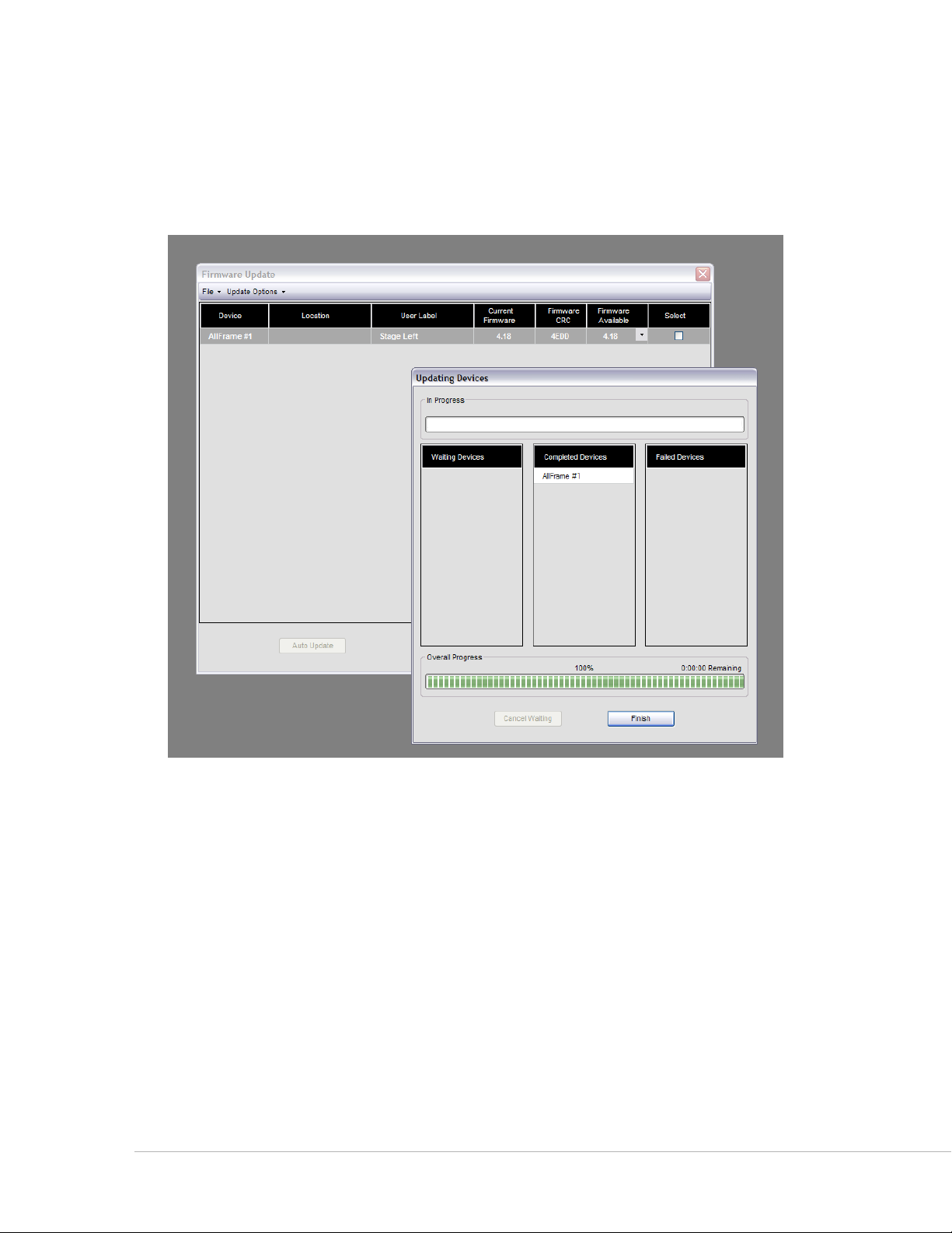
Progress Bars
During the firmware update process, progress bars and an info window will be displayed. The Updating
Devices window will show a list of all Pro64 devices that have been selected for updating. Devices will be
listed in the co m p l e t e D De v I c e s column once their firmware has been updated. If errors occur during the
update process, the device’s name will appear in the FA I l e D De v I c e s column.
Firmware Update window progress information
To close the Updating Devices window, click the FI N I s h button once all firmware updates have been
completed. To stop the update process for Pro64 devices that remain in the list, click the cA N c e l wA I t I N g
button. Note that the firmware update in progress must be completed before you will be allowed to exit.
If a Firmware Update Fails
If a Pro64 device fails the update process, try one of the following solutions:
Try a different null modem cable. •
Check the pinout on the RS‑232 cable with a multimeter. •
Keep all RS‑232 communication cables as short as possible. •
Try a different • USB‑to‑RS‑232 adapter.
Use a different PC. •
Relocate the Pro64 device, making it closer to the Control Master. •
Minimize cable distance (including Cat‑5 connections) between the Control •
Master and the device in question.
Pr o 64 Ne t w o r k Ma N a g e r Us e r gU i d e
31
Page 41

Closing the Firmware Update Window
Attempting to close the Firmware Update window while an update is in progress will cause a warning
dialog box to appear. The dialog box shows information about the current Pro64 device being updated,
and includes an estimate for the amount of time remaining for that firmware update to complete. It also
includes an estimate of the time required to complete all scheduled firmware updates.
You cannot exit the firmware update utility or quit Pro64 Network Manager until at least the currently
running firmware update is completed.
Stop one or more updates by clicking Cancel.
To exit the Firmware Update utility after the current update is completed and cancel all subsequent
updates, click the cA N c e l button in the dialog box. To continue the update process for all devices in the
Remaining Updates list, click the ok button.
Pr o 64 Ne t w o r k Ma N a g e r Us e r gU i d e
32
Page 42

Firmware Update Window Menus
Firmware Update
Control Master: 6416dio
Clock Master: 6416dio
Network Mode: Auto
Clock Mode: Internal
Network Sample Rate: 48kHz
Firmware Bootloader
Device Location Version CRC Version CRC
6416dio #1 3.42 F689 0.24 7B25
6416i #1 STAGE 3.42 7FBD 1.23 33F1
6416m #1 STAGE 3.42 A860 1.04 4B2E
6416o #1 FOH 3.42 7FBD 1.23 33F1
MH10f #1 FOH 3.42 B546 1.13 33C0
When the Firmware Update window is open the following menu commands are available:
File Menu
Print Opens the standard Windows OS printer selection dialog box and
allows you to print a report showing the current firmware versions for all
devices in the network (shortcut ‑ Ctrl+P)
Close Window Closes the Firmware Update window (shortcut ‑ Ctrl+W)
Firmware Report
Printing a firmware update report provides a written record of the network’s current firmware revisions.
Update Options Menu
Locate Update Files Opens a dialog box that allows you to navigate the computer’s hard
Refresh Update
Files
Use Default Update
Files
Pr o 64 Ne t w o r k Ma N a g e r Us e r gU i d e
Sample content from a rmware report
disks to locate the folder where the firmware update files are stored. Use
this to choose a firmware update folder other than the default.
This command refreshes the Firmware Update window view and should
be used if the devices in the network or the contents of the firmware
update files folder changes while the Firmware Update window is open.
Select this command to reset the location of the firmware updates files
back to the default.
33
Page 43

Commands in the Update Options menu
The default location for firmware update files is:
C:\Program Files\Aviom\Pro64 Network Manager\Device Update\Update Files or
C:\Program Files (x86)\Aviom\Pro64 Network Manager\Device Update\Update Files
This screen shot shows the default location for device update les stored in the application’s folder.
Pr o 64 Ne t w o r k Ma N a g e r Us e r gU i d e
34
Page 44

Maintaining a Pro64 Network
Once a Pro64 network is updated to the current version of the firmware to work with the Pro64 Network
Manager software, you should periodically check for new firmware update files to keep your Pro64
products up to date. Updates are posted to the Aviom website. (See page 21 for additional update and
firmware information.)
Pro64 devices with new rmware available are indicated in red.
Once new firmware files are downloaded and placed into the default firmware update file folder, any Pro64
devices that have new firmware available are indicated with red text when the Firmware Update window
is opened. Remember that you must be working online to be able to open the Firmware Update window.
Use the up D A t e Al l command found in the Update options menu to start the update process. Optionally,
select individual devices to be updated by clicking in their se l e c t boxes.
The default location for the firmware update files is:
C:\Program Files\Aviom\Pro64 Network Manager\Device Update\Update Files (Windows XP)
C:\Program Files (x86)\Aviom\Pro64 Network Manager\Device Update\Update Files (Windows 7)
P No t e : If you download new firmware files from the Aviom website, be sure they are placed in the
default Update Files folder so that they are automatically recognized by the Firmware Update
utility when the window is opened. If updates files are stored in a different folder you will need to
manually locate the firmware update files for each Pro64 device to be updated.
If 6416Y2 A‑Net Interface Cards are part of the network, refer to the card‑specific details on page 25 for
information on how to set up the card and update its firmware.
Pr o 64 Ne t w o r k Ma N a g e r Us e r gU i d e
35
Page 45

Adding Devices to a Network While Online
Adding one or more devices running outdated firmware to a v5.xx network while online will require the
devices with older firmware to be updated in order to retain control and management of the network
using Pro64 Network Manager.
An outdated device has been added to the network.
In the Network Overview window, the Status column will indicate incompatible devices with a red
exclamation point icon (!). Device Windows for any Pro64 devices that are not updated cannot be opened.
Projects cannot be saved or edited while such devices are connected. A dialog box opens warning of the
incompatibility. Click ok to continue; the network will switch to offline mode.
The network switches to oine mode when an incompatible devices is added to the network.
To continue managing a Pro64 network online, you must either update each incompatible device or
remove them from the network. Devices that have their firmware rolled back to previous firmware versions
are no longer compatible with the online network and must be removed before continuing.
Pr o 64 Ne t w o r k Ma N a g e r Us e r gU i d e
36
Page 46

oN l i N e v s . oF F l i N e
Pro64 Network Manager provides two ways of working with the settings and information related to a
Pro64 network—online and offline. The Network menu in the main workspace provides the commands
needed to go between the two states.
Working Online
Working online means that Pro64 Network Manager is connected to a group of Pro64 devices via an
RS‑232 or USB connection with the network’s Control Master, and that the user can monitor and change
the settings in the network. Working online allows the user to make changes to the network I/O routing
in real time, along with providing access to the Firmware Update utility. Settings can be saved in the form
of a project (described below). The project brings with it the option of creating and saving network‑wide
Scenes and/or device‑specific presets. See page 122 for information on the use of Scenes and see page 112
for complete information about using Device Presets.
The status bar will show a green Online LED when connected to a Pro64 network.
Working Offline
Once a project has been created, it can be edited offline without requiring the Pro64 network to be
connected to the PC. Most Pro64 Network Manager features and functions are available while working
offline; the Firmware Update utility is unavailable since no Pro64 hardware exists while offline.
Projects that are edited offline can be loaded back into the Pro64 network by reconnecting to the Pro64
network as long as the physical makeup of the network hardware is the same.
The status bar will show a yellow Oine LED when working without an active connection to a Pro64 network.
Pr o 64 Ne t w o r k Ma N a g e r Us e r gU i d e
37
Page 47

th e Pr o j e c t
Pro64 Network Manager saves all information about the configuration of a network in a structure called a
project. This includes:
Quantity and type of all Pro64 devices • in the network
Active • Slots on all I/O devices
Input and output Slot routing, including • matrix settings
Sample rate •
• Control Master device
• Clock Master device
• Clock source (Network, Word Clock, AES3)
Active • Virtual Data Cables (VDC)
Device • Numeric ID and Location labels
Channel names •
Network • Scenes
• Device Presets for each I/O device
User‑created text, • comments, etc.
Current open • windows and their positions
Only one project can be open at a time while working with Pro64 Network Manager. New projects can be
created while connected online to a Pro64 network or by using the sA v e pr o j e c t As... function with an
existing project open while working offline. Projects saved to disk can be opened and edited offline at any
time.
Project Contents
A project consists of a set of files and folders created as a group when you use the sA v e pr o j e c t command
for the first time when no project is open while working online, or when either the Ne w pr o j e c t or sA v e
pr o j e c t As.. command is used while an existing project is open. Projects can be stored in any convenient
location on the computer’s hard disk.
Saving a Project
When connected online to a Pro64 network, you can create and save a project by using the sA v e pr o j e c t
command found in the File menu of the main workspace. The shortcut for this command is Ctrl+S.
After navigating to an appropriate folder, enter a name for the project in the dialog box’s FI l e N A m e field
and then click the sA v e button. Once a project has been created, you can create a new project using the
same network configuration by using the Ne w pr o j e c t command found in the File menu in the main
workspace (the shortcut is Ctrl+N).
P No t e : Do not move or rearrange the project’s sub‑folders or their contents.
Pr o 64 Ne t w o r k Ma N a g e r Us e r gU i d e
38
Page 48

v
Create a project in any folder (1); name the project (2)
The newly saved project will include all current network I/O routing, text, and user‑created settings. Once
a project has been created and saved to disk, you have the option of creating Scenes and/or Device Presets
that become part of the project.
The Project Structure
Each project is created in its own folder with a layout like the one shown below; it contains the project
file itself as well as sub‑folders for Project Settings, Project Scenes, and Device Presets. All Pro64 Network
Manager projects use the .nmp file extension.
A project’s folder structure
Pr o 64 Ne t w o r k Ma N a g e r Us e r gU i d e
39
Page 49

As you work with a project the application will create new Scene and Device Preset files as needed and
store them in the sub‑folders that were created with the project. When working with Scenes and Device
Presets you will be prompted to confirm any operation that overwrites or deletes one of these files.
Scenes vs. Device Presets
A Device Preset saves the configuration of a single Pro64 I/O device and includes all channel names,
channel and Slot input and/or output routing, etc., making them the ideal way to store commonly used
settings for one device. Recalling a Device Preset will only affect the settings of the individual device. If
recalling a Device Preset requests a network Slot resource that is already in use by another device, that
request will be denied.
A Scene, on the other hand, stores the configuration of every device in the Pro64 network including the
channel/Slot I/O routing for all devices, user labels and comments in the Network Overview, Virtual Data
Cable settings, user‑generated text, and notes for the Scenes themselves.
There is no requirement to create
Scenes are a great way to simplify I/O management of a Pro64 network if you regularly use the same group
of configurations—a digital transfer between Recording and Broadcast studios, a Stage to FOH digital
snake with a monitor split, connecting the DAW to the Video Room, etc.
Each configuration saved as a Scene can be recalled quickly from within a project without the need to shut
down the Pro64 Network Manager application or configure front‑panel settings on the I/O modules.
Device Presets or Scenes when working with a project.
The Device Presets view for a 6416m
P No t e Scenes are designed to change the configuration of an entire audio network with a single click of
the mouse. Depending on the makeup of the network and the length of cabling involved, it will
take a short amount of time to load the new configuration, during which the network’s audio will
be muted. Pro64 Network Manager Scenes should not be confused with mixing console scenes
and automation designed for seamless transitions in a real‑time mixing environment.
Pr o 64 Ne t w o r k Ma N a g e r Us e r gU i d e
40
Page 50

The Scene Manager window
You can choose to work using any combination of the project file, Scenes, and Device Presets. Once a
project has been created, all information about the current network is stored when the project is saved
using the sA v e pr o j e c t command in the File menu of the main workspace.
Project Compatibility
Any projects saved to disk are checked for compatibility with the current network when they are opened
while working online or when you attempt to transition from working offline to online.
It is important to remember that the quantity and type of the Pro64 devices in the network as well as
the specific Pro64 devices set as Control Master and Clock Master are directly tied to the project when
it is created. A saved project that has any of the above‑described properties different from the current
network can be opened offline for editing but cannot be loaded into the online Pro64 network until the
networks match. In addition, remember that an AllFrame device’s specific card configuration including the
installed location and quantities of each card type is tied to the project.
The makeup of the network could be different for a number of reasons including devices not being
powered up, the addition/deletion of Pro64 devices, damaged or missing cables, etc.
P No t e : AllFrame devices are user configurable and as such must contain the exact complement of I/O
cards which must be installed in the same card slots within the F6 in order to remain compatible.
Pr o 64 Ne t w o r k Ma N a g e r Us e r gU i d e
41
Page 51

Transitioning From Online to Offline
When connected online to a Pro64 network, you can break the active connection between the host
computer and the Pro64 network by working offline. To change from online to offline operation, choose
wo r k oF F l I N e ... from the Network menu of the main workspace. The RS‑232 or USB connection between
the Control Master and the PC can be removed at this point if required, and the Pro64 network itself can
be shut down if necessary.
Once offline, the settings in the current project can be edited as needed, and the project can be saved
to disk as described above. New Scenes and Device Presets can be added to the project while working
offline, as well. However, the makeup of the network cannot be changed. There is no way to remove a
Pro64 device from the device list seen in the Network Overview. See page 53 for information on using the
Network Overview.
Online operation shows a green LED and oine operation shows a yellow LED in the status bar.
Transitioning From Offline to Online
While Pro64 Network Manager is offline, there are different scenarios that will affect what happens when
you attempt to transition from offline to online operation. The first is the easiest—there is no project open
and the workspace is blank. Simply select the wo r k oN l I N e ... command from the Network menu and
connect to the network after selecting a COM port via the dialog box prompts that follow.
Pro64 Network Manager then scans the network and uploads all the settings from the Pro64 devices into a
new workspace that you can control, edit, and save as a project.
Choose the COM port and then click OK to connect online.
Going Online With an Unsaved Project Open
An unsaved project can be open offline, as would happen if you started working online first and then
made the transition to offline without saving a project.
Pr o 64 Ne t w o r k Ma N a g e r Us e r gU i d e
42
Page 52

In this case the project must first be tested to check that it is compatible with the Pro64 network hardware
that it is being connected to. (Remember, the Pro64 device list, Control Master device, and Clock Master
device all must match.)
Choose wo r k oN l I N e ... from the Network menu to start the transition process. The following illustrates the
options that are available when transitioning from offline to online without having created a project first.
When wo r k oN l I N e ... is selected from the Network menu, the following dialog box appears:
The transition dialog box
Click cA N c e l to exit the dialog box and continue working offline.
Click the sA v e button to store the current settings to disk as a project. In the Save dialog box, navigate to
an appropriate directory and then name and save the project.
Click DI s c A r D to close the project that is currently open without saving changes.
After using the Save or Discard options, the Connect to Network dialog boxes (as described previously) will
appear. The network is now connected online.
If you selected the Save option in the previous dialog box, the project and its settings remain open. Since
the settings from the offline project (channel activation, channel names, I/O routing, etc.) may be different
from the actual settings of the online Pro64 hardware’s front panels, you will be given the opportunity to
choose which settings will be used—those from the offline project or those from the Pro64 hardware.
The following dialog box appears:
Pr o 64 Ne t w o r k Ma N a g e r Us e r gU i d e
The Upload or Send dialog box
43
Page 53

Two choices are available. Click up l o A D to gather the settings from the Pro64 hardware devices into the
project. The on‑screen settings (channel activation, channel names, I/O routing, etc.) may change and will
now exactly reflect the current state of the Pro64 hardware front panels. Immediately saving these settings
as a Scene guarantees that you can always recall the exact configuration that gets uploaded.
The other option is to click the se N D button to transfer the settings from the current project into the Pro64
hardware devices.
Once one of these options has been selected, the network can be edited online as needed. The Pro64
network and Pro64 Network Manager are now in sync.
Going Online With a Saved Project Open
You can transition from online to offline operations as often as needed. If you start working online, save a
project, and then transition to work offline, returning to online operation will behave as follows.
When the Project Has Not Changed
If nothing in the project has been edited and no windows have been repositioned, etc., when wo r k
oN l I N e ... is selected from the Network menu, the Connect to Network dialog boxes will appear. Select the
appropriate COM port and click ok to continue. The network is now connected online.
Once connected online, the Send Settings to Network dialog box appears:
The Upload or Send dialog box
Two choices are available. Click up l o A D to gather the settings from the Pro64 hardware devices into the
project. The on‑screen settings may change and will now exactly reflect the current state of the Pro64
hardware front panels. Immediately saving these settings as a Scene guarantees that you can always recall
the exact configuration that gets uploaded.
The other option is to click the se N D button to transfer the settings from the current project into the Pro64
hardware devices.
Pr o 64 Ne t w o r k Ma N a g e r Us e r gU i d e
44
Page 54

When the Project Has Changed
When wo r k oN l I N e ... is selected from the Network menu while working with a project but the project
settings have changed, the following dialog box appears:
The Save Project dialog box
Click sA v e to update the current project files on disk. Click sA v e As... to save a copy of the project with a
different name. Click cA N c e l to exit the dialog box and return to working offline.
As seen in the previous examples, the Send Settings to Network dialog box appears next. Click up l o A D to
gather the settings from the Pro64 hardware devices into the project or click the se N D button to transfer
the settings from the current project into the Pro64 hardware devices.
Pr o 64 Ne t w o r k Ma N a g e r Us e r gU i d e
45
Page 55

Wo r k s P a c e Fe a t U r e s
The workspace holds all other Pro64 Network Manager windows. The workspace can be sized and
positioned on the PC desktop by the user. Closing the main workspace window exits the application.
Workspace Status Bar
The application’s main Status Bar shows global information in a single row along the bottom of the
workspace window. Included are online/offline status, network mode, sample rate, clock source, as well as
Control Master and Clock Master info.
The workspace status bar runs along the bottom of the workspace.
Online/Offline Status
The first item in the Status Bar indicates the current network state—online or offline. When online
(connected to a Pro64 network), a green icon with the text “Online” appears. When offline, the text reads
“Offline” and a yellow icon is displayed.
Control Master
The Control Master section of the Status Bar is a read‑only field that shows the type of Pro64 device
currently set as the network’s Control Master along with that device’s numeric ID number.
Network Mode
This section of the status bar displays the network mode; currently Pro64 Network Manager supports only
Auto Mode systems. This is a read‑only field.
Clock Master
The network’s Clock Master device and its numeric ID number are shown on the right side of the Status
Bar; this is a read‑only field.
Clock
The Clock section of the Status Bar indicates the type of clock being used by the network. This is a read‑
only field. Settings displayed here can include Network Clock (internal), or External Clock.
Pr o 64 Ne t w o r k Ma N a g e r Us e r gU i d e
46
Page 56

Clock Errors
If a clock error occurs while synced to an external clock source, the clock type field will display the error
condition with red text as seen below.
A clock error is indicated in red.
The network will continue to operate using its internal clock until the error is corrected and the external
clock is restored, or until you intentionally reconfigure the Clock Master to use internal (Network) clock.
Sample Rate
The Sample Rate pop‑up is a user‑selectable field. Click on the arrow to open a list of the available network
sample rates from 44.1 to 192kHz. You will be prompted to confirm a network‑wide sample rate change as
this can affect the makeup of the network itself and the total number of available Slots.
Sample Rate selection
P No t e : Choosing a sample rate has an impact on the total number of Slots available for use in a network.
See the documentation that came with your Pro64 devices for additional information.
Mute All
The Mute All command will temporarily mute all audio outputs while making changes to network
hardware, positioning microphones, etc. When activated from the command in the Network menu of the
workspace, mu t e Al l is shown in red in the status bar. The temporary Mute All state is not saved as part of
the project. (Shortcut: Ctrl+Shift+1)
Mute All as seen in the status bar
P No t e : The Mute All function is not available when working with a project offline.
Pr o 64 Ne t w o r k Ma N a g e r Us e r gU i d e
47
Page 57

Workspace Window Commands
Right‑click the title bar of the workspace to open the standard (Windows OS) commands for resizing,
minimizing, and closing the window.
Right-click the title bar of the workspace to access the standard OS-level window commands.
The window management commands duplicate those found in the workspace window’s upper right
corner—Minimize, Maximize, and Close.
The standard window management commands
P No t e : Using the Close command (or its keyboard shortcut Alt+F4) is the same as quitting the Pro64
Network Manager application.
Pr o 64 Ne t w o r k Ma N a g e r Us e r gU i d e
48
Page 58

Workspace Menu Commands
The menu commands found in the main workspace are described below.
Workspace menus
File Menu
The File menu offers the following commands:
New Project Opens a dialog box that allows you to navigate to a folder on your hard
disk and choose a storage location and name for a new project. The
new project is based on the current network configuration. All channels
are deactivated and channel parameters are set to factory default
conditions. Scenes and Device Presets are cleared. (shortcut ‑ Ctrl+N)
Open Project Opens a dialog box that allows you to navigate to a folder on your hard
disk and choose a project to be opened
(shortcut ‑ Ctrl+O)
Save Project Saves the current project (shortcut ‑ Ctrl+S)
Save Project As... Opens the Save dialog to allow you to save a copy of the current project
with a different name (shortcut ‑ Ctrl+Shift+S)
Close Project Closes the current project; leaves the workspace open
Exit Quits the Pro64 Network Manager application (shortcut ‑ Alt+F4)
Network Menu
The Network menu commands control online/offline status.
Work Online... Opens a dialog box that allows you to connect to a Pro64 network. Open
projects are checked for compatibility with the online network.
Work Offline... When connected to a Pro64 network that is being managed online, this
command breaks the communication connection between the PC and
the Pro64 hardware allowing you to make edits without being physically
connected to the network.
Mute All Use the Mute All command to temporarily mute all audio outputs. A red
“Mute All” is shown in the workspace status bar while the outputs are
muted. Repeat the command to return to normal operation.
(shortcut ‑ Ctrl+Shift+1)
This item is not available when working offline.
Pr o 64 Ne t w o r k Ma N a g e r Us e r gU i d e
49
Page 59

Tools Menu
Use the Tools menu commands to access the Firmware Update utility and preferences.
Update Firmware... Opens the Firmware Update utility
This item is not available when working offline.
Preferences Opens the Preferences dialog box
Windows Menu
The Windows menu provides shortcuts to the application’s main windows.
Network Overview Opens the Network Overview window (keyboard shortcut Ctrl+1)
Scene Manager Opens the Scene Manager window (keyboard shortcut Ctrl+2)
Virtual Data Cable
Monitor
Audio Slot Manager Opens the Audio Slot Manager window (keyboard shortcut Ctrl+4)
Event Log Opens the Event Log window (keyboard shortcut Ctrl+5)
Close All Closes all currently open windows but does not quit the Pro64 Network
Open Windows List This section of the menu lists all currently open windows; selecting a
Opens the Virtual Data Cable (VDC) Monitor window
(keyboard shortcut Ctrl+3)
Manager application.
window from the list will bring it to the front for editing
About the Open Windows List Contents
The contents of the Open Windows List will change as you open and close the various windows that are
part of the Pro64 Network Manager application. Selecting any of the numbered windows with the mouse
(or typing the corresponding number on the PC keyboard once the menu is open) will select that window
and bring it into focus.
Pr o 64 Ne t w o r k Ma N a g e r Us e r gU i d e
50
Page 60

Items in the Windows menu
Help Menu
Application support is found in the Help menu.
Pro64 Network
Manager Help
Online Support Launches your browser and goes to the Aviom website support area
About Pro64
Network Manager
Pr o 64 Ne t w o r k Ma N a g e r Us e r gU i d e
Opens the User Guide for the application; the document is in PDF format
and requires Adobe Reader or equivalent
Opens a dialog box that shows the application version number and
other support information.
51
Page 61

Ne t W o r k ov e r v i e W Fe a t U r e s
The Network Overview contains the following information about the Pro64 network and its active devices:
Information is arranged in table format in rows and columns. Open the Network Overview from the main
workspace by choosing Ne t w o r k ov e r v I e w from the windows menu or by using the shortcut Ctrl+1.
The following information is displayed:
• Status – The blue A‑Net icon signifies that a Pro64 device is active in the network
• Device Type – 6416m, MH10, ASI, etc.
• Device Numeric ID – Used to help identify multiple devices of the same type
• Location – A user‑defined field based on where a Pro64 device is installed
• User Label – User editable text, 16 characters maximum
• Input Slot Range – The current Slot range setting for each input‑capable Pro64
device
• Output Slot Range – The current Slot range for each output‑capable Pro64 device
• Remote Control – Shows the Control Group setting for 6416m, RCI, and 6416Y2
• Comments – User‑defined text, 256 characters maximum
The Network Overview is arranged in columns and rows; data can be sorted by clicking the column headings.
Pr o 64 Ne t w o r k Ma N a g e r Us e r gU i d e
52
Page 62

th e Ne t W o r k ov e r v i e W iN t e r F a c e
Pro64 devices in the Network Overview can be selected singly or in groups. Click any field in a row to
highlight a device. Shift‑click to select multiple devices consecutively, or Control‑click to choose non‑
contiguous devices from the list.
The Network Overview window can be resized as needed while running the application. If the Network
Overview is made smaller than the default size, scroll bars will appear to allow any row or column to be
brought into focus. The Network Overview can be minimized by clicking the Minimize icon in the window’s
title bar.
Changing Column Widths
Columns in the Network Overview can be resized as needed. To change a column width, position the
mouse cursor in the headings area between any two columns until a left/right arrow icon appears. Click
and drag the separator to the desired width.
Click and drag the column separator to change the column width.
Sorting the Network Overview
Information displayed in the Network Overview can be sorted as needed by clicking the column headings.
Sorting can be ascending or descending and the current sort selection will be indicated in the column
heading with a triangle icon. The following columns can be sorted:
Device•
Location•
User Label •
• Input Slot Range
• Output Slot Range
Status Column
A blue A‑Net icon appears in the Status column to indicate an active Pro64 device. A red exclamation point
icon (!) will be displayed if a Pro64 device with old firmware is added to the network or if a device is unable
to communicate with the network because of corrupt firmware, hardware failure, etc.
Pr o 64 Ne t w o r k Ma N a g e r Us e r gU i d e
53
Page 63

The Status column also holds special icons used for the front panel lock feature (see page 55) and the LED
Device Identify function.
Blue icons indicate active Pro64 device, the red exclamation point indicates a device that needs to be updated.
For 6416Y2 cards installed in Yamaha devices, a yellow A‑Net icon is used to indicate a card in the network
that is not set up for control from Pro64 Network Manager. See page 27. A gray Status icon is used to
indicate Standby Mode for AllFrame devices.
LED Device Identify Feature
When working online with a Pro64 network, the LED Device Identify feature causes the front panel LEDs
on a device to flash to help identify it, a function that is useful during system setup and firmware updates,
especially when multiple devices of the same type are installed in the same location. The LED Device
Identify feature is available from the Device menu or via a right‑click on any row of the Network Overview.
To activate the LED Device Identify feature for one or more Pro64 devices, first select the device(s) in the
Network Overview. Then do one of the following: choose leD De v I c e ID e N t I F Y oN from the Device menu or
right click one of the selected rows and choose leD De v I c e ID e N t I F Y oN from the contextual menu.
Right-click to access the menu (left). Three devices have their LED Device Identif y function on (right).
Pr o 64 Ne t w o r k Ma N a g e r Us e r gU i d e
54
Page 64

When the LED Device Identify function is on, a white icon appears in the Status column of the Network
Overview for the selected device.
To turn off the LED Device Identify feature for an individual Pro64 device, select the device in the Network
Overview and then choose leD De v I c e ID e N t I F Y oF F after right‑clicking in the device’s row to select it. To
clear all front panel flashing related to use of the LED Device Identify feature, right‑click anywhere in the
Network Overview and choose Al l leD De v I c e ID e N t I F Y oF F from the contextual menu.
Use the shortcut Ctrl+I to activate the LED Device Identify feature and Ctrl+Shift+I to clear it.
Front Panel Lock/Unlock
The front panel of each Pro64 I/O device in the current network can be locked from the Pro64 Network
Manager application to prevent edits being made from the hardware’s front panels. Devices can be locked
individually or in groups.
The following Pro64 devices are capable of being locked:
• 6416i Input Module
• 6416o Output Module
• 6416m Mic Input Module
• 6416dio Digital I/O Module
To lock the front panel of a compatible device, select the device in the Network Overview and then choose
lo c k Fr o N t pA N e l from the Device menu. When a device’s front panel is locked, a lock icon appears in the
Status column of the Network Overview and in the status bar of its Device Window.
The lock icon in the Status column indicates that a device is edit locked.
To lock more than one device, Shift‑click or Control‑click compatible device rows in the Network Overview
to select them and then choose lo c k Fr o N t pA N e l from the Device menu (keyboard shortcut Ctrl+L). Or, to
lock all compatible devices without needing to select individual devices in the list first, simply choose lo c k
Al l Fr o N t pA N e l s from the Device menu (or use the keyboard shortcut Ctrl+Alt+L).
To unlock one or more devices, select them in the Network Overview and then choose uN l o c k Fr o N t
pA N e l from the Device menu (or use Ctrl+Shift+L). To unlock all locked devices without needing to select
individual items first, choose uN l o c k Al l Fr o N t pA N e l s from the Device menu (or use the keyboard shortcut
Ctrl+Alt+Shift+L).
The lock/unlock commands are duplicated in the Network Overview’s right‑click contextual menu for
convenience.
Pr o 64 Ne t w o r k Ma N a g e r Us e r gU i d e
55
Page 65

The following Pro64 devices have no Edit Lock control on their front panel interfaces and cannot be
locked:
• 6416Y2 A‑Net Interface Card for Yamaha®
• AllFrame
• MH10 and MH10f Merger Hubs
• ASI A‑Net Systems Interface
• RCI Remote Control Interface
Device Column
The Device column lists all Pro64 devices in the network by type. Numbers can be appended to the device
type when multiple devices of the same type are part of a network (6416m #1, 6416m #2, etc.) by changing
the device’s Numeric ID. Click the column heading to sort devices by type.
Numeric ID
Each Pro64 device in a network can be identified with a number (up to 3 digits). This unique ID is stored
in the hardware itself and can only be changed from the Pro64 Network Manager application. When new
Pro64 devices are added to a network they do not have a Numeric ID associated with them. In the Network
Overview and Device Windows they are displayed as (New Device).
Devices without Numeric IDs are identied as New Device
To set (or change) a Numeric ID for a Pro64 device, select a device (6416m, 6416o, etc.) in the Network
Overview and choose eD I t Nu m e r I c ID... from the Device menu or right‑click on the row and choose the
eD I t Nu m e r I c ID... command from the contextual menu.
Right-click to access the Numeric ID menu item
Pr o 64 Ne t w o r k Ma N a g e r Us e r gU i d e
56
Page 66

In the Numeric ID dialog box enter a number from 1‑999 and then click the ok button to close the dialog
and apply the new ID number.
Enter numbers from 1-999
The Numeric ID is stored in the Pro64 device itself until changed, and retains the setting as new projects
are created and edited.
P No t e : Since the Numeric ID is stored in the hardware itself, it is possible to give two Pro64 devices the
same Numeric ID. To avoid confusion when working with a network, it is suggested that each
Pro64 device of the same type be given a unique Numeric ID.
Control Master and Clock Master Indicators
Two special icons are used to indicate the network’s Control Master and Clock Master devices. A red square
icon indicates the Control Master and a yellow square icon is used for the Clock Master.
6416dio #1 is the network’s Control Master and Clock Master.
The Control Master designation for a Pro64 device is set on the hardware itself and cannot be changed
from within Pro64 Network Manager.
Filtering the Network Overview
Pro64 devices displayed in the Network Overview can be filtered from view if desired without affecting
network operations. To filter the list, right‑click anywhere on a device row and select FI l t e r se t t I N g s from
the contextual menu, or use the FI l t e r se t t I N g s ... command from the View menu (shortcut Ctrl+F) to open
the Filter dialog box.
P No t e : Filters do not affect the makeup of the Pro64 network or the allocation of network Slot resources.
Pr o 64 Ne t w o r k Ma N a g e r Us e r gU i d e
57
Page 67

The Network Overview’s local Status Bar will read FI l t e r oN when any data type in the Network Overview
is being filtered. The current filter settings are saved with the project.
The Filter Dialog Box
You can filter combinations of devices and Slot I/O ranges from a central location by using the controls in
the filter dialog box, found in the View menu of the Network Overview. To access the filter, choose FI l t e r
se t t I N g s ... from the View menu or right‑click in the Network Overview and select the command from the
contextual menu; the dialog box will open. (The keyboard shortcut is Ctrl+F)
Set and clear lter combinations from the lter dialog box.
Device types can be shown or hidden using the check boxes; uncheck a device type to hide it. Input and
output Slot ranges can also be filtered from view; uncheck any range to hide it. Each sub‑section of the
filter has its own Show All button that allows the filter to be reset quickly. Once the filters are applied to
your liking, click the ok button to close the dialog box and activate the filter. Click the cA N c e l button to
exit without changing the filter settings.
The bottom of the filter dialog box also has two global filter commands. Click re s e t to return each device
type and Slot I/O range to the default (on) state. Use uN c h e c k Al l to set all the check boxes to their off
state, useful as a starting point when you want to create a filter with only a few parameters included.
Location Column
A Location is a user‑defined text label in the Network Overview that is used to define where a device is
installed in the current Pro64 network and aid in sorting and managing devices in large systems. Click the
column heading to sort the network by Location.
Pr o 64 Ne t w o r k Ma N a g e r Us e r gU i d e
58
Page 68

Sort by Location by clicking its column heading.
To add location text for a device, click in the Location field in the Network Overview for the desired device.
When the text cursor appears, enter up to 16 characters of text. The Location label is stored in the Pro64
device and with the project.
Location information entered in this column is displayed in the other windows of Pro64 Network Manager
such as the Device Windows.
User Labels
The User Label column in the Network Overview provides a user‑defined text field (16 characters or less) for
each Pro64 device in the network. Text can be entered in the Network Overview or from a Device Window.
User Labels are stored in the Pro64 device and get saved with Scenes and the project.
Sort by the User Label by clicking its column heading.
Click in a User Label field in either the Network Overview of a Device Window to edit text; there is a
16‑character maximum. Press the keyboard eN t e r key or click elsewhere in the window to finish.
Pr o 64 Ne t w o r k Ma N a g e r Us e r gU i d e
59
Page 69

Input/Output Slot Range Displays
In the Network Overview, a pair of Slot Range columns show the current Slot range for each input‑ and
output‑capable Pro64 device. These are read‑only fields. Slot ranges can be changed from the Device
Window for each I/O device. Slot range information does not apply to network devices such as the MH10,
MH10f, ASI, or RCI.
Valid input and output Slot Range settings (depending on the current sample rate) include:
1‑16 (44.1/• 48kHz, 88.2/96kHz, and 176.4/192k Hz)
17‑32 (44.1/48kHz, and 88.2/96kHz)•
33‑48 44.1/48kHz)•
49‑64 (44.1/48kHz)•
• Mat rixe d (44.1/48kHz, 88.2/96kHz, and 176.4/192kH z)
Click the input or output column heading to sort the Network Overview device list by Slot range.
Filtering by Slot Range
The Network Overview can be filtered by Slot range if desired. To filter the list by Slot range, choose FI l t e r
se t t I N g s ... from the View menu. (See page 58.)
Remote Control
The Remote Control column of the Network Overview shows the Control Group setting for any device
capable of using remote control (valid settings are 1‑4 and off). This is a read‑only field.
Comments Field
The Network Overview’s Comments field is a user‑defined text area that is stored with individual Scenes
and with the project. Each Scene can recall a unique set of Comments as needed for an application.
To add a comment, click in the Comments field for any network device. When the text cursor appears
enter text of up to 256 characters. (Comments are not stored in the Pro64 device.)
Pr o 64 Ne t w o r k Ma N a g e r Us e r gU i d e
Enter up to 256 characters in the Comments eld.
60
Page 70

Network Overview Menus
This section describes the menus and commands available in the Network Overview.
File Menu
The File menu offers the following commands:
Print... Prints a report detailing the current network settings
Print Preview Displays a preview of the information that will be printed in the Network
Overview report
Close Window Closes the Network Overview (shortcut ‑ Ctrl+W)
To print a report containing all the information shown in the Network Overview, choose pr I N t ... from the
File menu. The standard OS print dialog box will open, allowing you to select any connected printer and
set page properties.
To view the report prior to printing select pr I N t pr e v I e w from the File menu.
Network Report
Print a network report from the Network Overview to create a record of the current state of the network
including all devices, location names, user labels and comments, and channel/Slot ranges.
A sample network report
To close the Network Overview, choose cl o s e wI N D o w or use the keyboard shortcut Ctrl+W. The project
remains open. To reopen the Network Overview, choose Ne t w o r k ov e r v I e w from the main workspace’s
Windows menu (or use the keyboard shortcut Ctrl+1).
Pr o 64 Ne t w o r k Ma N a g e r Us e r gU i d e
61
Page 71

Edit Menu
The Edit menu in the Network Overview offers the following commands that can be used when editing
text labels and comments
Cut Cuts the selected text (shortcut ‑ Ctrl+X)
Copy Copies the selected text to the clipboard (shortcut ‑ Ctrl+C)
Paste Pastes text that was copied to the clipboard (shortcut ‑ Ctrl+V)
Undo Undoes the last cut, clear, or paste operation (shortcut ‑ Ctrl+Z)
These commands become active once you have entered a valid, editable text field.
View Menu
The View menu provides access to the Filter Settings... dialog box. (See page 58.)
Device Menu
The Network Overview’s Device menu provides access to the LED Device Identify feature as well as the
front panel lock/unlock feature. See page 54 for information on the LED Device Identify feature.
Open Device Window Opens the Device Window for the selected Pro64 device
(shortcut ‑ Ctrl+D)
LED Device Identify On Flashes the LEDs on the front panel of the selected Pro64 device to
LED Device Identify Off Clears the selected device’s front panel LED flashing when using the
All Device Identify Off Clears the LED Device Identify flashing for all devices (shortcut
Lock Front Panel Locks the front panel of the selected Pro64 device; a lock icon is
Lock All Front Panels Locks the front panel of the all Pro64 devices in the network; a lock
Unlock Front Panel Unlocks the front panel of the selected Pro64 device
Unlock All Front Panels Unlocks the front panel of all Pro64 devices
make it easy to identify; a white square icon is added to the Status
column when the feature is on (shortcut ‑ Ctrl+I)
LED Device Identify function
(shortcut ‑ Ctrl+Shift +I)
‑ Ctrl+Alt+Shift +I)
added to the Status column (shortcut ‑ Ctrl+L)
icon is added to the Status column for each (shortcut ‑ Ctrl+Alt+L)
(shortcut ‑ Ctrl+Shift +L)
(shortcut ‑ Ctrl+Alt+Shift +L)
•
Pr o 64 Ne t w o r k Ma N a g e r Us e r gU i d e
62
Page 72

de v i c e Wi N d o W Fe a t U r e s
A Device Window contains the unique settings for each type of Pro64 device. Most Device Windows have
multiple views used to simplify managing data for a specific device type, along with a local menu bar used
for accessing commands and features related to that device.
To open a Device Window, select a row in the Network Overview and then double click it.
Device Windows showing the various views
A Device Window can also be opened by using the shortcut ct r l +D when a device’s row is selected in the
Network Overview.
Pr o 64 Ne t w o r k Ma N a g e r Us e r gU i d e
63
Page 73

Window Views
The following views are available for the Device Windows:
• Device Overview – the most compact view; available for all devices
• Inputs to Network – AllFrame, 6416i, 6416m, 6416dio, and 6416Y2 only
• Outputs from Network – AllFrame, 6416o, 6416dio, 6416Y2, and ASI only
Inputs and Outputs• – AllFrame, 6416dio and 6416Y2 only
• Device Presets (Show All) – AllFrame, 6416i, 6416o, 6416m, 6416dio, 6416Y2, and ASI
• Port Names – MH10/MH10f only
I/O modules have multiple views available.
Select the view you want to use from the device’s View menu. The RCI device window does not require a
View menu; all information is displayed in its overview.
Fields in the Device Overview
The device type, number, location, and user label are displayed at the top of each Device Overview. These
fields are common to all device types and mirror the text seen in the Network Overview.
User Label
To change the User Label text, click in the label area. The text highlights; type in a new name to replace
the existing text or use the cursor, arrow keys, backspace and delete keys to edit an existing text label.
Changes to the User Label will be reflected immediately in the Network Overview.
Pr o 64 Ne t w o r k Ma N a g e r Us e r gU i d e
64
Page 74

Status Bar
Each Device Window contains a read‑only status bar along its bottom edge. A copy of the A‑Net status
icon from the Network Overview will appear in the device window along with Control Master and Clock
Master icons as needed.
v
w
x
y
Device type and number (1), Location (2), User Label (3), network mode eld (4), and status bar (5)
Input/Output Grids
Pro64 input‑ and output‑capable devices will have I/O grids in their device windows. Bidirectional devices
such as the AllFrame, 6416Y2 A‑Net Interface Card and 6416dio Digital I/O Module will have both types.
Exceptions are noted in the sections that follow.
The grids serve a twofold purpose—they provide a quick overview of channel and Slot use on each Pro64
device and they can be used to quickly activate channels and assign them to network Slots; simply click a
channel to activate/deactivate it.
Inputs are displayed in green, outputs are yellow. The input and output channel grids are numbered 1‑16,
corresponding to the 16 physical connections on the rack‑mount Pro64 I/O devices.
Input grid (left) and output grid (right) with Slot range drop down menus
Pr o 64 Ne t w o r k Ma N a g e r Us e r gU i d e
65
Page 75

AllFrame I/O Grids
AllFrame devices have slightly different I/O grid displays because their I/O hardware is user‑configurable.
The top section of the Device Window will show a table of the installed I/O cards, using letters corresponding
to the card’s installed location plus channel numbers on the card (A1‑A4, D1‑D4, etc.). Individual on/off
switches are provided in the Input and Output grids based on the actual cards installed. Inputs or outputs
that are not applicable to a certain card slot will be grayed out. The basic functionality of the iI/O switches
is the same as that for the rack‑mounted Pro64 I/O devices: click to activate or deactivate a Slot.
P No t e : An AllFrame device’s inputs are not automatically assigned to network Slots; this must be done
using the Inputs to Network view on a per‑channel basis prior to activating an input.
The Device Overview for an AllFrame device shows its installed cards as well as the current state of all I/O slots.
Pr o 64 Ne t w o r k Ma N a g e r Us e r gU i d e
66
Page 76

Slot Range
Within the Input/Output grid is a Slot range drop down menu (not available on AllFrame devices). This is
used to assign a Pro64 device to either one of the four 16‑channel Slot ranges used by the network or to
the matrix. Available settings are Slot 1‑16, Slot 17‑32, Slot 33‑48, Slot 49‑64, or Matrixed.
Remember that the current network sample rate affects the total number of input Slots that are available
to be activated (64 Slots at 44.1/48kHz; 32 Slots at 88.2/96kHz; 16 Slots at 176.4/192kHz).
Choose a new Slot range from the drop down menu.
To change a Slot range setting, click in the drop down menu and select a new Slot range or Matrixed.
You will be prompted to confirm the change. For input devices, all currently activated channels will be
deactivated when a new 16‑channel Slot range is selected to avoid conflicts with input Slots already active
in the network on other Pro64 devices. Activating the matrix does not deactivate the Slot assignments.
Pr o 64 Ne t w o r k Ma N a g e r Us e r gU i d e
67
Page 77

Activating Channels
To assign a channel on a Pro64 input device to a network Slot, click the channel’s on‑screen Ac t I v e button.
Green Active LEDs appear in both the Device Overview and Inputs to Network views. The input channel
and its corresponding network Slot now available to all output devices in the network
Click either Active LED to assign an input to a network Slot.
Activating All Channels
The Device Window’s Channel Settings menu provides a shortcut command that can activate and assign
all channels on an input device to the network. Choose Ac t I v A t e Al l IN p u t ch A N N e l s from the menu; if any
conflicts exist they will be reported in the Channel Activation Warning window.
The Activate All Input Channels command in the Channel Settings menu
Pr o 64 Ne t w o r k Ma N a g e r Us e r gU i d e
68
Page 78

AllFrame devices are always assigned to the matrix and have no default channel routing. Before an AllFrame
input channel can be activated and assigned to the network, it must be assigned to a network Slot first.
Channel/Slot Conflicts
If the assigned network Slot is currently in use by another Pro64 input device, the Channel Activation
Warning window will appear to warn you of the resource conflict. Click ok to close the dialog box. To
resolve the conflict, assign the input channel to an unused network Slot or change the assignment for the
Slot in question on the device currently assigned to use it.
The Channel Activation Warning shows any resource allocation conicts.
Information in the Channel Activation Warning window is displayed in rows and shows the requested input
channel number, the channel name, the requesting Pro64 network device, the Slot where the conflict has
occurred, and the channel number, name, and Pro64 device currently using the Slot in question.
The Channel Activation Warning window may remain open as resource conflicts are resolved, but will not
update automatically. Resize the window as needed by using the grab bar in the lower right corner of the
window.
Pr o 64 Ne t w o r k Ma N a g e r Us e r gU i d e
69
Page 79

Deactivating Slots
To deactivate an active Slot on an input device, click the green channel LED; the LED will turn off and the
Slot resource is made available to other devices in the network.
There are no restrictions on output modules; their channels can be turned on/off at any time. No warning
dialogs are required. The 6416Y2 Yamaha card is an exception; its outputs are always active.
Assigning Input Channels to the Matrix
The matrix capabilities of Pro64 Network Manager allow any input channel on a Pro64 device to be
assigned to any network Slot, simplifying complex routings. To access the matrix functionality, a Pro64
device must first be set to mA t r I x e D in the Slot range drop down, found in its Device Window. (AllFrame
devices have their inputs assigned to the matrix by default.)
Once a device has been set to Matrixed, the Inputs to Network view changes to reveal the routing options
for each input channel on the device.
Once Matrixed is selec ted in the Slot range menu, clicking the arrow next to a Slot’s current assignment will open the
selection menu. Select a new Slot assignment by clicking it number.
In the Select Slot dialog box, The current Slot assignment is shown in green; available, unassigned Slots are
displayed with standard text while Slots that are already active in the network are displayed in italics. The
top of the Select Slot dialog box also offers the option of selecting no channel/Slot assignment, displayed
as No N e . Hovering the cursor over a Slot number while the dialog box is open will show the Slot’s channel
name and source device (if applicable) or sl o t Av A I l A B l e .
Pr o 64 Ne t w o r k Ma N a g e r Us e r gU i d e
70
Page 80

Control Groups
For remote‑controllable devices capable of belonging to a Control Group (6416m, AllFrame, RCI, and the
6416Y2 card when m‑control™ is active), the Control Group drop down menu will appear in the Device
Window. Select a Control Group from the drop down menu to change the Control Group for the device
currently being edited; available settings are Control Groups 1‑4 and 'Off.'
Control Group can be set to one of the four groups or 'o.'
P No t e : The 6416Y2 A‑Net Interface Card is always assigned to one of the four Control Groups when
m‑control is in use and has no 'off' setting available.
A device must be assigned to a Control Group to send or receive remote control information.
Pr o 64 Ne t w o r k Ma N a g e r Us e r gU i d e
71
Page 81

de v i c e -sP e c i F i c Fe a t U r e s
In addition to the common features described previously, some of the Device Windows also contain
device‑specific features that are described below.
AllFrame
The Device Overview for the F6 Modular I/O Frame, which is part of the AllFrame Multi‑Modular I/O System
(displayed on screen simply as AllFrame) shows which optional I/O cards have been installed into each of
its six card slots.
The AllFrame I/O Card table displays the installed cards for each AllFrame.
Pr o 64 Ne t w o r k Ma N a g e r Us e r gU i d e
72
Page 82

Cards are identified by letter, A through F, corresponding to the location in the F6 where the I/O card is
installed. The input and output channels within an I/O card are numbered 1 through 4, and are displayed
with the corresponding location’s letter prefix (A1‑A4, B1‑B4, etc.) in the Device Window.
AllFrame I/O card locations are identied by letter.
Pr o 64 Ne t w o r k Ma N a g e r Us e r gU i d e
73
Page 83

AllFrame C4dio Card Support
When a C4dio Digital I/O Card is installed in an AllFrame, the AllFrame can use external clocks in the form
of Word Clock or the clock embedded within a digital AES3 stream. Each C4dio card installed can be a
clock source. To support this feature, the AllFrame Device Window has an Audio Clock Source drop‑down
menu with options that correspond to the C4dio cards and their installed locations.
Two clock options are available per C4dio card installed: Word and AES. In the drop‑down menu the
options are displayed in a list with the C4dio card’s installed location (by letter, A‑F) in the F6 hardware as
seen below.
External clock options for a C4dio card installed into slot C of an F6
Choose the card and clock type from the list and then confirm the change in the dialog box that opens
once a selection has been made. The network will lock to the external clock. If the external clock is not
present, or fails while being used, the network switches automatically to its internal clock.
Pr o 64 Ne t w o r k Ma N a g e r Us e r gU i d e
74
Page 84

Clock change conrmation dialog box
When an external clock source is being used, the Device Overview for the AllFrame will display a red dot
next to the C4dio card that is the clock source.
An external clock source is indicated by a red dot.
C4dio Sample Rate Converters.
The C4dio card includes sample rate converters (SRC) that allow external devices to be connected to a
Pro64 network without clock artifacts caused by out‑of‑sync clocks. The sample rate converters operate in
pairs and are on by default when a C4dio card is installed in an AllFrame.
The Inputs to Network view contains an SRC column that shows the state of the sample rate converters;
a yellow square indicates that a sample rate converter pair is active. The on/off state of the sample rate
converters save with device presets.
When the sample rate converters are active, a C4dio card cannot be used as an AES3 clock source.
Attempting to activate AES as a clock source will result in a warning dialog box. Turn the sample rate
converters off and try again.
Sample rate converter warning
Pr o 64 Ne t w o r k Ma N a g e r Us e r gU i d e
75
Page 85

Sample rate converters on a C4dio card installed in slot F of an AllFrame
Pr o 64 Ne t w o r k Ma N a g e r Us e r gU i d e
76
Page 86

AllFrame Standby Options
AllFrame devices in a network can be placed into standby and remain on the network while I/O cards
are changed. Three versions of standby are supported: software controlled from the AllFrame’s Device
Window, from the AllFrame hardware’s front panel Standby momentary switch, or by using a wired contact
closure connected to the Standby Euroblock connector on the top panel on the unit.
Standby informations appears in the Device Window’s Overview.
When an AllFrame is in standby its Status icon in the Network Overview will be displayed in gray. Changes
to routing, mic preamp settings, output levels, etc., can still be made but will not be available until the
AllFrame is out of standby.
The AllFrame’s Status icon in the Network Overview is gray when the device is in Standby.
Pr o 64 Ne t w o r k Ma N a g e r Us e r gU i d e
77
Page 87

Standby From the Device Window
To put the AllFrame in Standby from the Device Window while online, click the oN button in the Standby
Mode section of the Device Window. The On button lights and a yellow warning triangle icon appears.
The AllFrame’s I/O resources are disabled, but A‑Net continues to flow for all network connections. The
device’s status icon in the Network Overview is gray while the AllFrame is in standby.
An AllFrame placed into Standby from the Device Window
While in standby, an AllFrame’s I/O cards can be changed. However, if a saved project is open when the
AllFrame I/O is changed, the AllFrame will no longer be compatible when it comes back online—its
hardware complement is different.
To return the AllFrame to normal network operation, click the Standby Mode oF F button. The AllFrame’s
I/O resources are again available to the network.
Standby From the F6 Front Panel
To place an AllFrame into Standby from the hardware’s front panel, press the gray momentary st A N D B Y
button found beneath the control panel cover plate. This action duplicates the functionality previously
described for the activation of Standby Mode from within Pro64 Network Manager—the AllFrame’s audio
I/O resources are suspended and A‑Net continues to flow for all connected network devices. I/O Cards in
the F6 can be swapped as needed. To return the AllFrame to normal operation, press the gray st A N D B Y
button or click the oF F button in the AllFrame Device Window in the software.
Pressing the gray front panel Standby switch performs the same function as using the software switch.
Pr o 64 Ne t w o r k Ma N a g e r Us e r gU i d e
78
Page 88

Standby From a Contact Closure
Standby Mode can also be activated by wiring a contact closure switch to the Standby Euroblock connector
on the top panel of the F6 hardware. This allows a physical switch to trigger the standby state as might
required if the AllFrame was built into an electrical enclosure with a door that was to be closed when the
device was not in use. To differentiate this type of Standby behavior from that initiated by software or the
momentary switch it is referred to as Hardware Standby.
An AllFrame in hardware standby
When an AllFrame is placed into Standby Mode using a physical contact closure device, it will display a
special lock icon in the Device Window that reads hA r D w A r e st A N D B Y Ac t I v e in red along with the yellow
warning triangle. (Notice that the Standby Mode’s radio button remains set to oF F in this case.) Pro64
Network Manager cannot change this standby state. The contact closure must be opened manually to
return the AllFrame to normal operation.
P No t e : When an AllFrame is in Hardware Standby it cannot then be placed into software standby.
Pr o 64 Ne t w o r k Ma N a g e r Us e r gU i d e
79
Page 89

Hardware and Software Standby Together
Both types of Standby can be used simultaneously if the AllFrame enters the software version of Standby
first. If while the AllFrame is in software Standby, a hardware contact closure is triggered on the same
AllFrame device, both types of Standby will be in force. On screen in the Device Window, the Standby
Mode oN radio button with be lit and the red hA r D w A r e st A N D B Y Ac t I v e will also be on.
An AllFrame in hardware standby
To exit this state, the hardware contact closure needs to be opened manually (the software Standby will
still be in force). Then, the software Standby can be disabled by either clicking the on‑screen oF F button in
the Device Window or pushing the gray st A N D B Y momentary switch on the AllFrame hardware.
Standby and External Clocks
When an AllFrame device is the network’s Control Master and is set to use external AES or Word Clock,
entering standby will force the clock source to be set to Network (internal) clock while the AllFrame is in
standby. When the AllFrame comes out of standby the external clock will again be the network’s clock
source, as long as the C4dio card containing the clock connection is in the same physical location (slot A‑F)
in the AllFrame hardware and the external clock source is still connected.
Pr o 64 Ne t w o r k Ma N a g e r Us e r gU i d e
80
Page 90

AllFrame C4o Output Levels
The analog audio outputs on an AllFrame device with one or more C4o Analog Output Cards installed can
be set to one of five levels: +28dBu, +24dBu, +18dBu, +4dBu, or Mic.
Use the drop-down menu to select an analog output level for a C4o output.
Click the drop‑down menu arrow to reveal the output level choices for a channel. The output level settings
save as part of a device preset, making presets ideal for recalling frequently used configurations for an
AllFrame device. Output level settings also save as part of the network‑wide Scenes. Save a project first
before attempting to save a Scene or Device Preset.
Pr o 64 Ne t w o r k Ma N a g e r Us e r gU i d e
81
Page 91

Clearing AllFrame Output Level Settings
The Channel Settings menu contains two commands that can be used to clear AllFrame analog output
level settings. Choose cl e A r ou t p u t ch A N N e l se t t I N g s to reset the selected channel back to its default,
+24dBu. Use the cl e A r Al l ou t p u t ch A N N e l se t t I N g s command to set all analog outputs back to the default
setting.
The Clear Output Channel Settings commands return analog outputs to the default +24dBu setting.
Save AllFrame output levels as part of a Device Preset or Scene to simplify device configuration and setup.
P No t e : The output level reset commands are only available on AllFrame devices.
Pr o 64 Ne t w o r k Ma N a g e r Us e r gU i d e
82
Page 92

6416Y2 A-Net Interface Card
ON
ON
ON
ON
ON
ON
SW7
SW8
SW3
SW9
SW4
SW1
SW2
1 2 3 4 5 6 7 8 9 10
1 2 3 4 5 6 7 8 9 10
1 2 3 4 5 6 7 8
1 2 3 4 5 6 7 8
1 2 3 4 5 6 7 8
1 2 3 4 5 6 7 8
ON
SW9
1 2 3 4 5 6 7 8 9 10
The 6416Y2 can be set up to follow the configuration of its onboard DIP switches or to use the configuration
sent to it from the Pro64 Network Manager application. The programmed settings from Pro64 Network
Manager are retained even after the PC is removed from the network.
To enable control of the 6416Y2 card via Pro64 Network Manager, set DIP switch #9 found in DIP Switch
Block 9 (SW9) to the up position after its firmware has been updated. All 6416Y2 cards in the network must
be set this way in order to be controllable from Pro64 Network Manager. (This switch must be in the down
position for the firmware update.)
Detail view of block SW9 showing DIP switch #9 in the up position to enable Pro64 Network Manager control
Remember that if a 6416Y2 card is the network’s Control Master, DIP switch #10 in block SW9 (Managed
Mode on) must also be in the up position.
When DIP switch #9 in block SW9 is in the down position, the 6416Y2 card will use the settings from its
onboard DIP switches and no changes from Pro64 Network Manager will be allowed. The 6416Y2 card will
still appear as a valid Pro64 device in the Pro64 Network Manager windows while online, but no changes
to any I/O routing, configuration settings, or text edits such as channel names will be allowed until DIP
switch #9 in block SW9 is set to the up position.
How DIP Switch #9 Works
There is only one set of I/O routing parameters available for the 6416Y2 card at a time; DIP switch #9 chooses
which set is used—the one programmed from Pro64 Network Manager or the one defined by the actual
DIP switch settings on the card. Moving DIP switch #9 in block SW9 from the Pro64 Network Manager
control enabled position (up) to local DIP switch control (down) will clear the programming performed
from within Pro64 Network Manager until the switch is returned to the up position and the card (along
with its Yamaha host device) is reconnected to the PC and the settings restored.
Saving a Device Preset will help assure that settings can always be restored to a 6416Y2 card. See page 112
for more information on using Device Presets.
Pr o 64 Ne t w o r k Ma N a g e r Us e r gU i d e
83
Page 93

6416Y2 Status Icon
In the Network Overview window the 6416Y2 card’s Status column displays a blue A‑Net icon to indicate
that the card can be controlled. A non‑controllable card will have a yellow A‑Net status icon. The same
status icon is seen in the card’s Device Window.
The yellow icon indicates that the card is not controllable.
The yellow A-Net icon indicates a card that is not controllable.
m-control
Using m‑control to provide remote preamp control from a Yamaha device requires the user to set DIP
switch #10 on the card’s front panel to the ‘on’ position (down) in order to activate the function; it cannot
be activated from within the Pro64 Network Manager software. When m‑control is activated for one or
more 6416Y2 cards in the network a special icon will appear in the Device Window for each card. The
card configuration dialog box for choosing m‑control settings is available in the Tools menu of the card’s
Device Window. See page 89 for more information.
Pr o 64 Ne t w o r k Ma N a g e r Us e r gU i d e
84
Page 94

The m-control icon appears for any 6416Y2 card that has DIP switch #10 activated.
Install the 6416Y2 card into Yamaha MY slot #1 when using m-control.
A 6416Y2 card that is set to be the network’s Control Master cannot also have m‑control active. If the
network has only one 6416Y2 card installed, there are two options: set a different Pro64 device as the
Control Master or work without m‑control enabled. In a network with multiple 6416Y2 cards installed,
simply activate m‑control on a card that is not the Control Master.
P No t e : The m‑control feature needs to be disabled during firmware updates.
VDC Settings
When a 6416Y2 card is used as the network’s Control Master, no Virtual Data Cables can be assigned to
that 6416Y2 card while the Pro64 Network Manager application is connected and actively managing the
network.
Pr o 64 Ne t w o r k Ma N a g e r Us e r gU i d e
85
Page 95

MY8 and MY16 Modes
It is important to note that the choice to use the Yamaha MY8 or MY16 mode (8‑channel versus 16‑channel
communication) must be set by the user via the 6416Y2 card’s DIP switches before installing the card in a
Yamaha host device; it cannot be controlled via software. Refer to the 6416Y2 card and Yamaha product’s
documentation for additional information abut the use of the two MY modes.
In the 6416Y2 device windows, any 6416Y2 cards running in MY8 mode will have input and output channels
9‑16 disabled as seen below.
Pr o 64 Ne t w o r k Ma N a g e r Us e r gU i d e
Channels 9-16 are disabled in MY8 mode.
86
Page 96

6416Y2 Output Slots
Active Pro64 network Slots coming into a Yamaha device via a 6416Y2 card are always available to be
output from the card to the Yamaha console. The Yamaha operator makes the choice to use a Pro64
network resource by patching one or more Pro64 network Slots into the Yamaha device for mixing and/or
processing as needed. For this reason, the output Slots (as seen in all device views) for 6416Y2 cards in the
network are always on; their yellow LEDs in the Device Window cannot be changed.
6416Y2 card output Slots are always on.
P No t e : The 6416Y2 card’s Device Window does not allow output channels to be turned off.
Clicking an output Slot on a 6416Y2 will cause this warning dialog box to appear.
Pr o 64 Ne t w o r k Ma N a g e r Us e r gU i d e
87
Page 97

6416Y2 Card Stereo Links
Pro64 Network Manager adds simplified programming for input modules capable of using stereo links.
However, the 6416Y2 card uses physical DIP switches on its front panel for activating a stereo link for a
channel pair. These switches are not software controllable.
In the 6416Y2 card’s Device Window there are no software stereo link commands available (unlike other
Pro64 input devices), but any active stereo links will be displayed. Changes to 6416Y2 channel pairs can be
made at any time using the DIP switches on the front face of the card; the on‑screen display will update
immediately.
Stereo links are active on channels 3-4 and11-12.
All channel activation rules still apply for stereo links on 6416Y2 cards—channels to be stereo linked must
be an odd‑even pair and both channels must be active in the network before a stereo link can be used.
The Status icon will be yellow if a 6416Y2 card is configured to use the settings from its internal DIP switches
instead of those coming from the software; a card in this state cannot be edited or controlled. This status
icon mirrors the one seen in the Network Overview.
Pr o 64 Ne t w o r k Ma N a g e r Us e r gU i d e
88
Page 98

Card Configuration Dialog Box
The Tools menu for the 6416Y2 Card’s Device Window contains a shortcut to the Card Configuration dialog
box. The settings here control the Pad Mode, Serial interface communication, and m‑control channel/Slot
options.
Pr o 64 Ne t w o r k Ma N a g e r Us e r gU i d e
The 6416Y2 Card Conguration options
89
Page 99

Card Mode
The 6416Y2 card mode can be set to either MY16 or MY8. Yamaha’s MY16 offers 16 channels at 44.1/48kHz
while MY8 mode offers 8‑channel operation, useful for Yamaha devices capable of using the 96kHz sample
rate or when the card is used with the PM1D console. This field is read‑only; the mode is set with DIP switch
#10 in switch block SW8 on the card itself.
m-control
The m‑control field in the Card Configuration dialog box is read‑only; m‑control can only be activated
from the front panel of the 6416Y2 card by placing DIP switch #10 in the down position. Using m‑control
allows remote control of Pro64 preamp settings directly from the interface of supported Yamaha devices.
Pad Mode
When using m‑control with Pro64 remote controllable mic preamps (as found in the 6416m and AllFrame)
there are user‑selectable options that control how the 24dB pad built into the remote preamps operate.
Two choices are available: Auto Pad and Manual Pad.
Pad Mode options in the Card Conguration dialog box
Choose Au t o pA D to allow the remote control commands coming from the Yamaha device to automatically
turn the Pro64 mic preamp’s pad on and off as needed. This mode provides the widest range of gain
settings for both mic‑ and line‑level audio sources by combining the 56dB range of the preamp with the
24dB pad for a total 80dB gain range. Note that the pad circuitry is in the analog domain for optimal audio
fidelity. When the pad is engaged or disengaged on the Pro64 mic preamp, audio will mute briefly while
the pad state is changed via relays to avoid unwanted noise in the audio system.
To separate the mic preamp gain from the pad, choose the mA N u A l pA D setting. When using Manual Pad
the preamp gain range is 56dB (displayed as 0 to +55 on Aviom devices). The 56dB range is mapped to the
73 available steps of the Yamaha control. The pad must be engaged or disengaged from the front panel of
a 6416m, from an RCI/MCS, or from Pro64 Network Manager.
P No t e : The on‑screen display of gain in a Yamaha device is limited to the interface provided the
operator by the Yamaha operating system; the numbers displayed on the Pro64 preamp and the
Yamaha controller will be different but the actual values and resulting audio levels will be the
same. Yamaha displays gain range relative to the signal strength of the channel’s input, typically
displayed as “+10” at the minimum and “‑62” at the maximum range of a control’s display.
Pr o 64 Ne t w o r k Ma N a g e r Us e r gU i d e
90
Page 100

Serial Interface
The Serial Interface field determines how the 6416Y2 card communicates with the Yamaha host device—
either from the rear panel Remote jack of the host device via a DB9 serial cable, or from the Yamaha device’s
backplane connector (currently required for the LS9, M7CL‑ES, and CL Series consoles).
Network Slots to be Remote Controlled
When m‑control is being used, the 6416Y2 card can be set up to control any or all of the available mic
preamps in the Pro64 network. Use the check boxes to select the group of Slots that should be controlled
from the Yamaha device (1‑16, 17‑32, 33‑48, and/or 49‑64) in any combination.
Select which mic preamps to control by clicking the check boxes.
P No t e : When controlling remote preamps with m‑control, remember that the Control Group setting
must match on both the sending and receiving devices.
Pr o 64 Ne t w o r k Ma N a g e r Us e r gU i d e
91
 Loading...