

Page 1
PB28
910
11
12 13
14
15
16
P
B
2
8
Modular Patch Bay User Guide
P
B
2
12345678 910111213141516
8
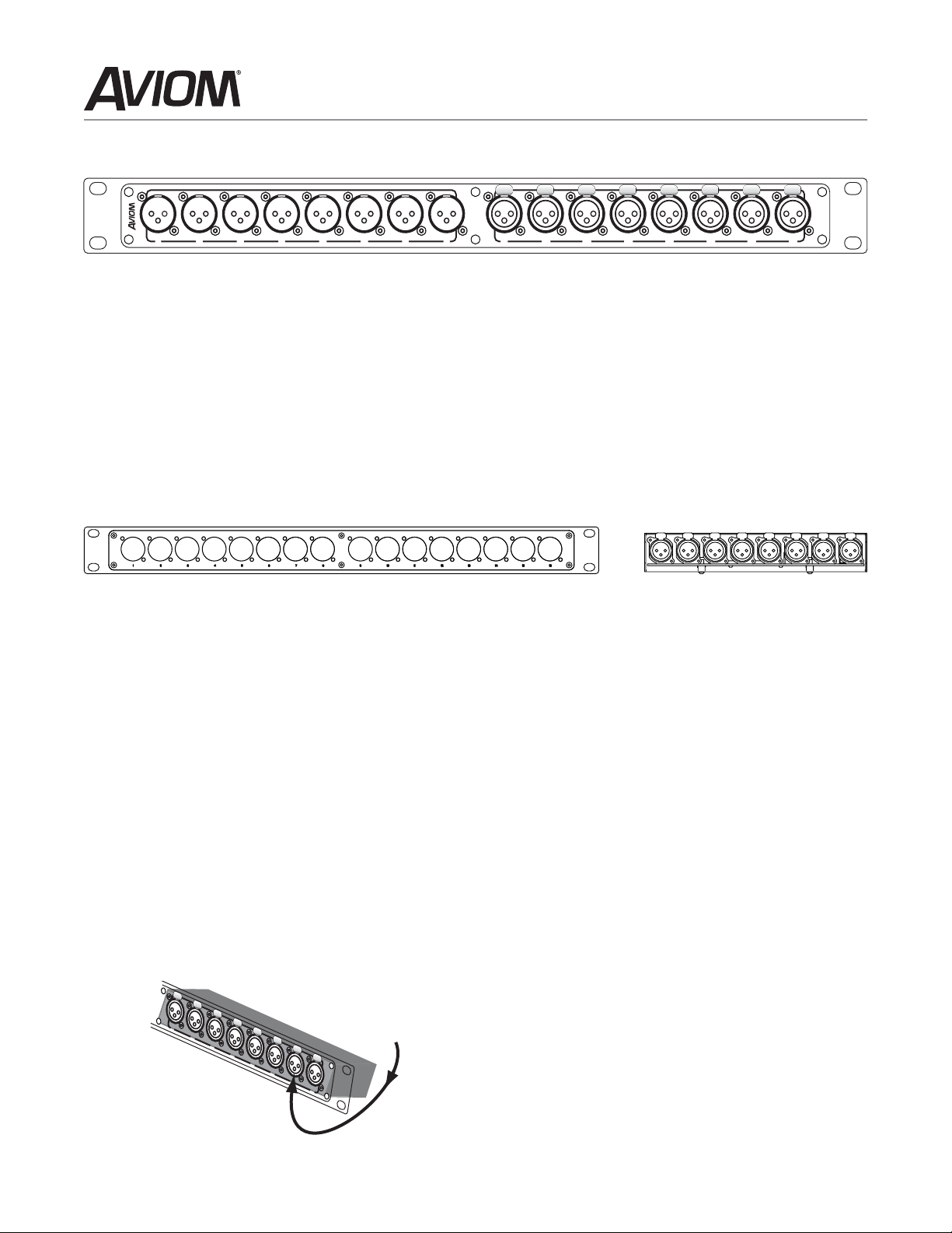
The PB28 Patch System
Aviom’s PB28 Patch Bay System is a universal modular
patching system that allows the user to configure
custom patch panels. PB28 patch bays can be used
in any audio or data environment. Each PB28 Patch
Panel accepts two eight-channel modules in any
order.
A Phillips screwdriver is required to mount the PB28
Series modules to the PB28 Patch Panel.
Assembly
The basis of the PB28 system is the PB28 Patch Panel,
a blank, 1U-high unit that accepts up to two PB28
Series modules. Secure the optional modules to the
PB28 Patch Panel before mounting the product in an
equipment rack.
To attach a PB28 Series module to the PB28 Patch
Panel:
Orient the blank PB28 Patch Panel with the
1.
channel numbers facing down.
Align the jacks on the front of the PB28 Series
2.
module with the holes numbered 1-8 or 9-16 in
the front panel of the PB28 Patch panel.
PB28 Series modules that have release tabs on
3.
the front (such as the EtherCon jack) should be
angled slightly downward before being passed
through the patch panel opening. Always mount
the module with the release tabs facing upward.
PB28 Modules
These modules are currently available for the PB28:
28-XF-DB XLR female (f) to DB25 (r)
•
28-XM-DB XLR male (f) to DB25 (r)
•
28-EC-EC EtherCon on both sides
•
28-XM-XF XLR male (f) to XLR female (r)
•
28-XF-XM XLR female (f) to XLR male (r)
•
28-AES-DB XLR male/female (f) to DB25 (r)
•
for AES/EBU digital data
Attach the module to the patch panel. Each PB28
4.
Series module comes with 16 screws that are
used to secure it to the front of the PB28 Patch
Panel. Always install all 16 screws.
Avoid excess force when attaching modules to the
PB28 Patch Panel. Hand-tighten the Phillips screws
to avoid stripping the threads on the PB28 Series
module.
Note: Using a power screwdriver can damage the
panel-mounted jacks on the PB28 Series
module.
Replacing a Module
To change the configuration of a patch bay or
exchange a PB28 Series module, first remove the
PB28 from the equipment rack. Remove any modules
with a Phillips screwdriver. Exchange or replace
modules by repeating the steps above.
Mounting the PB28 in a Rack
When rack mounting, be sure to use four screws—
one in each mounting hole—to ensure that the PB28
does not flex in the equipment rack.
Page 2
Aviom PB28 Modular Patch Bay User Guide
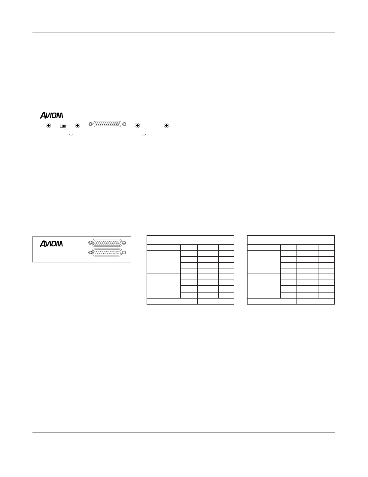
Confi guring PB28 Modules
Ground Switches on DB25 Connectors
A ground (earth) lift switch is provided on analog
modules using the DB25 connector. This switch is
provided to help troubleshoot ground problems.
Always start with the switch in the default
location as noted on the module’s rear panel art.
Analog Audio Input
DB25 Pin 13
Lift
Ground
(default)
The switch on the left side of the module will ground
Pin 13 of the DB25. In a standard DB25 audio pinout,
for example, this pin is not connected to ground.
Digital DB25 Connectors
The 28-AES-DB module provides eight channels
of AES/EBU digital I/O in stereo pairs, per the
AES specification. It is equipped with two DB25
connectors to accommodate the different AES wiring
pinouts currently in use by major manufacturers of
digital gear. Only one DB25 connector can be used at a
time.
PB28 Modular Patch Bay System
DB25 Shell
Ground
Lift
(default)
Made in USA
PB28 Cat-5 Modules
The 28-EC-EC is an eight-channel EtherCon RJ45
module featuring Neutrik EtherCon connectors on
both sides. It allows Cat-5 network connections
from multiple devices to be brought to a convenient
central location in any patch bay. The 28-EC-EC
module can be used with Aviom A-Net™ products or
with any Cat-5 based data system.
About the EtherCon Connector
The Neutrik EtherCon connector is a dual RJ45 type
connector. It can receive a standard Category 5e cable
or a cable fitted with the special heavy-duty locking
EtherCon connector.
When using a standard Cat-5e cable, plug the cable
into the center of the jack; release the cable by
pressing on the small plastic tab built into the cable
connector.
Insert an EtherCon equipped cable into the jack
until it clicks and locks in place. To remove the cable,
press on the metal release tab at the top of the
panel-mounted EtherCon jack and pull the connector
outward.
Tascam/Digidesign
Yamah a
Caution: Connect only one digital source at a time
AES/EBU Digital Data I/O
Yamaha AES Pinout
Data In
(stereo pairs)
The following tables describe the
pinout configurations used on the
28-AES-DB module.
Data Out
(stereo pairs)
Unused
Aviom, Inc. Limited Warranty
Aviom, Inc. warrants this product against defects in materials and
workmanship for a period of one year from the date of the original
retail purchase.
This warranty does not apply if the equipment has been damaged
due to misuse, abuse, accident, or problems with electrical power.
The warrant y also does not apply if the product has been modified
in any way, or if the product serial number has been damaged,
modified, or removed.
If a defect is discovered, first write or call Aviom, Inc. to obtain a
Return Authorization number. No service will be performed on
any product returned without prior authorization. Aviom, Inc. will,
at its option, repair or replace the product at no charge to you.
The product must be returned during the warranty period, with
transportation charges prepaid, to Aviom, Inc., 1157 Phoenixville
Pike, Suite 201, West Chester, PA 19380, USA. You must use the
product ’s original packing materials for shipment. Shipments
should be insured for the value of the product. Include your name,
address, phone number, description of the problem, and copy of
the original bill of sale with the shipment. The Return Authorization
number should be written on the outside of the box.
Aviom , Inc.
1157 Phoenixville Pike, Suite 201
West Chester, PA 19380 USA
www.aviom.com
Tascam/Digidesign AES Pinout
Hot Cold Gnd
114 22
215 10
316 23
417 24
518 12
619 25
720 13
821 13
9, 11
THIS LIMITED WARRANTY GIVES YOU SPECIFIC LEGAL RIGHTS. YOU
MAY HAVE OTHER RIGHTS, WHICH VARY FROM STATE TO STATE
(OR JURISDICTION TO JURISDICTION). AVIOM’S RESPONSIBILITY
FOR MALFUNCTIONS AND DEFECTS IN HARDWARE IS LIMITED
TO REPAIR AND REPLACEMENT AS SET FORTH IN THIS LIMITED
WARRANTY STATEMENT. ALL EXPRESS AND IMPLIED WARRANTIES
FOR THE PRODUCT, INCLUDING BUT NOT LIMITED TO ANY
IMPLIED WARRANTIES OF MERCHANTABILITY AND FITNESS FOR
A PARTICULAR PURPOSE, ARE LIMITED IN DURATION TO THE
WARRANTY PERIOD SET FORTH ABOVE. NO WARRANTIES, WHETHER
EXPRESS OR IMPLIED, WILL APPLY AFTER SUCH PERIOD.
AVIOM, INC. DOES NOT ACCEPT LIABILITY BEYOND THE REMEDIES
SET FORTH IN THIS LIMITED WARRANTY DOCUMENT. AVIOM, INC.’S
LIABILITY IS LIMITED TO THE REPAIR OR REPLACEMENT, AT OUR
OPTION, OF ANY DEFECTIVE PRODUCT, AND SHALL IN NO EVENT
INCLUDE INCIDENTAL OR CONSEQUENTIAL DAMAGES OF ANY KIND.
SOME STATES DO NOT ALLOW EXCLUSIONS OR LIMITATION
OF IMPLIED WARRANTIES OR LIABILIT Y FOR INCIDENTAL OR
CONSEQUENTIAL DAMAGES, SO THE ABOVE LIMITATIONS MAY NOT
APPLY TO YOU.
A-Net and the A-Net icon are trademarks of Aviom, Inc.
Copyright ©2006 Aviom, Inc. All rights reserved.
Information subject to change without notice. Printed in USA
Data In
(stereo pairs)
Data Out
(stereo pairs)
Unused
Hot Cold Gnd
24 12 25
10 23 11
21 9 22
720 8
18 6 19
417 5
15 3 16
114 2
13
P/N 9311 1010 0001 rev. 1.10
 Loading...