

Page 1

ALLFRAME
™
Multi-Modular I/O System
User Guide
P/N 9310 1024 0001F rev. 1.04
© 2012 Aviom, Inc.
Page 2

READ THIS FIRST
Important Safety Instructions
Read these instructions. 1.
Keep these instructions. 2.
Heed all warnings.3.
Follow all instructions.4.
Do not use this apparatus near water.5.
Clean only with a dry cloth.6.
Do not block any ventilation openings. Install in accordance with the manufacturer’s instructions.7.
Do not install near any heat sources such as radiators, heat registers, stoves, or other apparatus (including 8.
amplifiers) that produce heat.
Do not defeat the safety purpose of the polarized or grounding-type plug. A polarized plug has two 9.
blades with one wider than the other. A grounding type plug has two blades and a third grounding
prong. The wide blade or third prong are provided for your safety. If the provided plug does not fit your
outlet, consult an electrician for replacement of the obsolete outlet.
Protect the power cord from being walked on or pinched, particularly at plugs, convenience receptacles, 10.
and the point where they exit the apparatus.
Only use attachments/accessories specified by the manufacturer.11.
Use only with the cart, stand, tripod, bracket, or table specified by the manufacturer, or sold with the 12.
apparatus. When a cart is used, use caution when moving the cart/apparatus combination to avoid injury
from tip-over.
Unplug this apparatus during lightning storms or when unused for long periods of time.13.
Refer all servicing to qualified personnel. Servicing is required when the apparatus has been damaged in 14.
any way, such as when the power-supply cord or plug is damaged, liquid has been spilled or objects have
fallen into the apparatus, the apparatus has been exposed to rain or moisture, does not operate normally,
or has been dropped.
No on/off power switches are included in the system. The external power supply should be used to 15.
control power to an Aviom device. This power supply should remain readily operable.
The solid line over dashed line symbol (16. ) indicates that the input voltage must be a DC voltage.
The box within a box symbol ( 17. ) indicates that the external power supply is double insulated.
ii
Page 3

! !
TO REDUCE THE DANGER OF ELECTRICAL SHOCK DO NOT REMOVE COVERS.
NO USER SERVICEABLE PARTS INSIDE.
REFER SERVICING TO QUALIFIED SERVICE PERSONNEL ONLY.
To reduce the risk of fire or electrical shock, do not expose this product to rain or other types of moisture.
To avoid the hazard of electrical shock, do not handle the power cord with wet hands.
Replace fuse with same type and rating.
Operating Temperature: 0˚C to 50˚C (32˚F to 122˚F)
Risque de choc électrique – ne pas ouvrir. Pour réduire le risque de feu ou de choc électrique, ne pas exposer cet équipement à la pluie
ou la moisissure. Pour réduire le risque de choc électrique, ne pas retirer le couvercle. Pièces non remplaçables par l’utilisateur. Confier la
réparation à une personne qualifiée. Attention – utiliser seulement un fusible de rechange de même type.
Cet appareil est conforme à la section 15 de la norme FCC. Son fonctionnement est soumis aux conditions suivantes : (1) cet équipement ne
doit pas causer des interférences nocives, et (2) cet équipement doit accepter toute interférence captée incluant les interférences pouvant
causer des opérations indésirables.
Cet appareil numérique de Classe B est conforme à la norme NMB-003 du Canada.
WARNING!
IMPORTANT:
This equipment has been tested and found to comply with the limits for a Class B digital device, pursuant to
part 15 of the FCC Rules. These limits are designed to provide reasonable protection against harmful interference
in a residential installation. This equipment generates, uses and can radiate radio frequency energy and, if not
installed and used in accordance with the instructions, may cause harmful interference to radio communications.
However, there is no guarantee that interference will not occur in a particular installation. If this equipment does
cause harmful interference to radio or television reception, which can be determined by turning the equipment
off and on, the user is encouraged to try to correct the interference by one or more of the following measures:
Reorient or relocate the receiving antenna.•
Increase the separation between the equipment and receiver.•
Connect the equipment into an outlet on a circuit different from that to which the receiver is •
connected.
Consult the dealer or an experienced radio/TV technician for help.•
Changes or modifications to the product not expressly approved by Aviom, Inc. could void the user’s FCC authority
to operate the equipment.
CAUTION:
Using any audio system at high volume levels can cause •
permanent damage to your hearing.
Set your system volume as low as possible. •
Avoid prolonged exposure to excessive sound pressure levels.•
ii i
Page 4
Certifications
Pb
Pb-Free
EMC: EN 55103-1, EN 55103-2
Safety: EN 60065, UL 60065, CAN/CSA C22.2 No. 60065 + A1:2006
ETL/cETL Listed and RoHS Compliant
Notice of Rights
All rights reserved. No part of this document may be reproduced or transmitted in any form or by any means—
electronic, mechanical, photocopy, recording, or otherwise—without written permission of Aviom, Inc.
Trademarks
Aviom, A-Net, the A-Net icon, Pro16, Pro64, AllFrame, m-control, and Virtual Data Cable are
trademarks of Aviom, Inc.
All other trademarks are the property of their respective owners.
© 2012 Aviom, Inc. All rights reserved.
Information is subject to change without notice.
iv
Page 5

Aviom, Inc. Limited Warranty
Aviom, Inc. warrants this product against defects in materials and workmanship for a period of one year from the
date of the original retail purchase.
This warranty does not apply if the equipment has been damaged due to misuse, abuse, accident, or problems
with electrical power. The warranty also does not apply if the product has been opened or modified in any way;
if the product serial number has been damaged, modified, or removed; or if the original Quality Assurance label
has been damaged, modified, or removed.
If a defect is discovered, first write or call Aviom, Inc. to obtain a Return Authorization number. No service will be
performed on any product returned without prior authorization. Aviom, Inc. will, at its option, repair or replace
the product at no charge to you. The product must be returned during the warranty period, with transportation
charges prepaid to Aviom, Inc., 1157 Phoenixville Pike, Suite 201, West Chester, PA 19380. You must use the
product’s original packing materials for shipment. Shipments should be insured for the value of the product.
Include your name, address, phone number, description of the problem, and copy of the original bill of sale with
the shipment. The Return Authorization number should be written on the outside of the box.
THIS LIMITED WARRANTY GIVES YOU SPECIFIC LEGAL RIGHTS. YOU MAY HAVE OTHER RIGHTS, WHICH VARY
FROM STATE TO STATE (OR JURISDICTION TO JURISDICTION). AVIOM’S RESPONSIBILITY FOR MALFUNCTIONS AND
DEFECTS IN HARDWARE IS LIMITED TO REPAIR AND REPLACEMENT AS SET FORTH IN THIS LIMITED WARRANTY
STATEMENT. ALL EXPRESS AND IMPLIED WARRANTIES FOR THE PRODUCT, INCLUDING BUT NOT LIMITED TO
ANY IMPLIED WARRANTIES OF MERCHANTABILITY AND FITNESS FOR A PARTICULAR PURPOSE, ARE LIMITED IN
DURATION TO THE WARRANTY PERIOD SET FORTH ABOVE. NO WARRANTIES, WHETHER EXPRESS OR IMPLIED,
WILL APPLY AFTER SUCH PERIOD.
AVIOM, INC. DOES NOT ACCEPT LIABILITY BEYOND THE REMEDIES SET FORTH IN THIS LIMITED WARRANTY
DOCUMENT. AVIOM, INC.’S LIABILITY IS LIMITED TO THE REPAIR OR REPLACEMENT, AT OUR OPTION, OF ANY
DEFECTIVE PRODUCT, AND SHALL IN NO EVENT INCLUDE INCIDENTAL OR CONSEQUENTIAL DAMAGES OF ANY
KIND.
SOME STATES DO NOT ALLOW EXCLUSIONS OR LIMITATION OF IMPLIED WARRANTIES OR LIABILITY FOR
INCIDENTAL OR CONSEQUENTIAL DAMAGES, SO THE ABOVE LIMITATIONS MAY NOT APPLY TO YOU.
v
Page 6

Warranty Information
Please record the following information for future reference:
Your Authorized Aviom Dealer:
Name:
Address:
Phone:
Serial Numbers of Your Aviom Products:
Date of Purchase:
Your Authorized Aviom Dealer is your primary source for service and support. The information recorded above
will be helpful in communicating with your Authorized Aviom Dealer should you need to contact Aviom Customer
Service. If you have any questions concerning the use of this unit, please contact your Authorized Aviom Dealer
first. For additional technical support, or to find the name of the nearest Authorized Aviom Repair Station, check
the Aviom web site at www.aviom.com.
To fulfill warranty requirements, your Aviom product should be serviced only at an authorized Aviom service
center. The Aviom serial number label must appear on the outside of the unit, or the Aviom warranty is void.
This manual and its contents are copyrighted by Aviom, Inc. All rights are reserved by Aviom, Inc. This document
may not, in whole or in part, be copied, photocopied, reproduced, translated, or reduced to any electronic
medium or machine-readable form without prior written consent from Aviom, Inc.
The software and/or firmware contained within Aviom products is copyrighted and all rights are reserved by
Aviom, Inc.
Although every effort has been made to ensure the accuracy of the text and illustrations in this manual, no
guarantee is made or implied as to the accuracy of the information contained within.
v i
Page 7

Table of Contents
Certifications. . . . . . . . . . . . . . . . . . . . . . . . . . . . . . . . . . . . . . iv
Warranty Information . . . . . . . . . . . . . . . . . . . . . . . . . . . . . . . . vi
Welcome. . . . . . . . . . . . . . . . . . . . . . . . . . . . . . . . . . . . . . . . . . . 1
AllFrame System Components . . . . . . . . . . . . . . . . . . . . . . . . . . 1
The F6 Modular I/O Frame . . . . . . . . . . . . . . . . . . . . . . . . . . . . . 1
C4m Card . . . . . . . . . . . . . . . . . . . . . . . . . . . . . . . . . . . . . . . . 2
C4o Card. . . . . . . . . . . . . . . . . . . . . . . . . . . . . . . . . . . . . . . . . 3
C4dio Card . . . . . . . . . . . . . . . . . . . . . . . . . . . . . . . . . . . . . . . 3
Accessories . . . . . . . . . . . . . . . . . . . . . . . . . . . . . . . . . . . . . . . 4
RK6 Rack Kit . . . . . . . . . . . . . . . . . . . . . . . . . . . . . . . . . . . . . . 4
SK6 Stage Kit . . . . . . . . . . . . . . . . . . . . . . . . . . . . . . . . . . . . . . 4
LK4 Label Kit for C4m and C4o . . . . . . . . . . . . . . . . . . . . . . . . . . 4
HK6 Security Hardware Kit for F6 . . . . . . . . . . . . . . . . . . . . . . . . 4
Fan6 Replacement Fan Tray Assembly . . . . . . . . . . . . . . . . . . . . . 4
PLT6-s Surface-Mount Finishing Plate for F6 . . . . . . . . . . . . . . . . . 4
PLT6-f Flush-Mount Finishing Plate for F6 . . . . . . . . . . . . . . . . . . . 4
Power Supplies . . . . . . . . . . . . . . . . . . . . . . . . . . . . . . . . . . . . 5
POA80 Power Over A-Net Power Supply . . . . . . . . . . . . . . . . . 5
About A-Net . . . . . . . . . . . . . . . . . . . . . . . . . . . . . . . . . . . . . . . 6
Clocking . . . . . . . . . . . . . . . . . . . . . . . . . . . . . . . . . . . . . . . . 6
Control Data . . . . . . . . . . . . . . . . . . . . . . . . . . . . . . . . . . . . . . 6
A-Net Ports . . . . . . . . . . . . . . . . . . . . . . . . . . . . . . . . . . . . . . . 7
Support For Pro16 Series Products . . . . . . . . . . . . . . . . . . . . . . . 8
Firmware Notice . . . . . . . . . . . . . . . . . . . . . . . . . . . . . . . . . . . . . 9
Assembling the AllFrame System . . . . . . . . . . . . . . . . . . . . . . 10
Installing I/O Cards . . . . . . . . . . . . . . . . . . . . . . . . . . . . . . . . 10
Installing the F6 Mounting Brackets . . . . . . . . . . . . . . . . . . . . . 11
Installing SFP Fiber Transceivers . . . . . . . . . . . . . . . . . . . . . . . . 13
SFP Transceivers . . . . . . . . . . . . . . . . . . . . . . . . . . . . . . . . . . 13
LC Connectors . . . . . . . . . . . . . . . . . . . . . . . . . . . . . . . . . . . . 14
Cat-5e Cables . . . . . . . . . . . . . . . . . . . . . . . . . . . . . . . . . . . . 14
Ta b l e o f Co n T e n T s
v i i
Page 8

ALLFRAME
™
EtherCon Connector . . . . . . . . . . . . . . . . . . . . . . . . . . . . . . . . 15
RK6 Rack Kit . . . . . . . . . . . . . . . . . . . . . . . . . . . . . . . . . . . . . 16
Installing the RK6 . . . . . . . . . . . . . . . . . . . . . . . . . . . . . . . . . . 16
SK6 Stage Kit . . . . . . . . . . . . . . . . . . . . . . . . . . . . . . . . . . . . . 18
Installing the SK6 . . . . . . . . . . . . . . . . . . . . . . . . . . . . . . . . . 18
Powering the F6 Modular I/O Frame . . . . . . . . . . . . . . . . . . . . 22
Power Safety Warnings . . . . . . . . . . . . . . . . . . . . . . . . . . . . . . 23
For Power Over A-Net . . . . . . . . . . . . . . . . . . . . . . . . . . . . . . . 23
For DC Power via the XLR or Euroblock. . . . . . . . . . . . . . . . . . . . 23
System Connections . . . . . . . . . . . . . . . . . . . . . . . . . . . . . . . . 23
Power Supply Requirements . . . . . . . . . . . . . . . . . . . . . . . . . . 24
Power Cable Lengths . . . . . . . . . . . . . . . . . . . . . . . . . . . . . . . 24
Power Over A-Net (PoA) . . . . . . . . . . . . . . . . . . . . . . . . . . . . . 25
Connecting the POA80 Power Supply . . . . . . . . . . . . . . . . . . . . 25
Mounting the POA80 . . . . . . . . . . . . . . . . . . . . . . . . . . . . . . . 26
DC Power via the 4-Pin XLR . . . . . . . . . . . . . . . . . . . . . . . . . . . 27
DC Power via the Euroblock Connectors . . . . . . . . . . . . . . . . . . 28
Pro64 User Interface. . . . . . . . . . . . . . . . . . . . . . . . . . . . . . . . . 30
A-Net Slot . . . . . . . . . . . . . . . . . . . . . . . . . . . . . . . . . . . . . . . 30
Slots versus Channels . . . . . . . . . . . . . . . . . . . . . . . . . . . . . . . 30
A-Net Slot Example . . . . . . . . . . . . . . . . . . . . . . . . . . . . . . . . 31
Slots and Sample Rate . . . . . . . . . . . . . . . . . . . . . . . . . . . . . . 32
Network Settings . . . . . . . . . . . . . . . . . . . . . . . . . . . . . . . . . . . 33
Control Master . . . . . . . . . . . . . . . . . . . . . . . . . . . . . . . . . . . 33
Control Master Functions . . . . . . . . . . . . . . . . . . . . . . . . . . . . 34
Enumeration . . . . . . . . . . . . . . . . . . . . . . . . . . . . . . . . . . . . . 34
Adding Pro64 Devices to a Network . . . . . . . . . . . . . . . . . . . . . 35
Control Master Errors . . . . . . . . . . . . . . . . . . . . . . . . . . . . . . . 35
Clock Master . . . . . . . . . . . . . . . . . . . . . . . . . . . . . . . . . . . . . 35
Control Master and Clock Source . . . . . . . . . . . . . . . . . . . . . . . 36
Clock Errors. . . . . . . . . . . . . . . . . . . . . . . . . . . . . . . . . . . . . . 36
Sample Rates and A-Net Slots. . . . . . . . . . . . . . . . . . . . . . . . . . 36
F6 Front Panel Components. . . . . . . . . . . . . . . . . . . . . . . . . . . 37
Front Panel LEDs. . . . . . . . . . . . . . . . . . . . . . . . . . . . . . . . . . . . 39
Ta b l e o f Co n T e n T s
A-Net LED . . . . . . . . . . . . . . . . . . . . . . . . . . . . . . . . . . . . . . 39
vi i i
Page 9

ALLFRAME
™
Power Status LED . . . . . . . . . . . . . . . . . . . . . . . . . . . . . . . . . . 39
Control Master LED . . . . . . . . . . . . . . . . . . . . . . . . . . . . . . . . 39
Clock Master LED . . . . . . . . . . . . . . . . . . . . . . . . . . . . . . . . . . 40
Thermal Monitor LED . . . . . . . . . . . . . . . . . . . . . . . . . . . . . . . 40
Fan Monitoring . . . . . . . . . . . . . . . . . . . . . . . . . . . . . . . . . . . 40
Error LED . . . . . . . . . . . . . . . . . . . . . . . . . . . . . . . . . . . . . . . 40
Control Panel . . . . . . . . . . . . . . . . . . . . . . . . . . . . . . . . . . . . . . 41
Standby Switch . . . . . . . . . . . . . . . . . . . . . . . . . . . . . . . . . . . 41
Control Master Switch . . . . . . . . . . . . . . . . . . . . . . . . . . . . . . 42
USB Connector . . . . . . . . . . . . . . . . . . . . . . . . . . . . . . . . . . . 42
Fan Tray . . . . . . . . . . . . . . . . . . . . . . . . . . . . . . . . . . . . . . . . . . 43
I/O Card Slots . . . . . . . . . . . . . . . . . . . . . . . . . . . . . . . . . . . . . . 44
Card Slot ID . . . . . . . . . . . . . . . . . . . . . . . . . . . . . . . . . . . . . . 45
Installed I/O Cards . . . . . . . . . . . . . . . . . . . . . . . . . . . . . . . . . 45
I/O Card Cover Plates . . . . . . . . . . . . . . . . . . . . . . . . . . . . . . . 46
I/O Card Label Area . . . . . . . . . . . . . . . . . . . . . . . . . . . . . . . . 46
F6 Top Panel Features . . . . . . . . . . . . . . . . . . . . . . . . . . . . . . . 48
A-Net Ports . . . . . . . . . . . . . . . . . . . . . . . . . . . . . . . . . . . . . . 48
A-Net Via Cat-5e. . . . . . . . . . . . . . . . . . . . . . . . . . . . . . . . . . . 48
A-Net Via Fiber . . . . . . . . . . . . . . . . . . . . . . . . . . . . . . . . . . . 49
Optical Transceiver Safety . . . . . . . . . . . . . . . . . . . . . . . . . . . . 49
Power Connections . . . . . . . . . . . . . . . . . . . . . . . . . . . . . . . . 51
Standby Connectors . . . . . . . . . . . . . . . . . . . . . . . . . . . . . . . . 51
LED Defeat . . . . . . . . . . . . . . . . . . . . . . . . . . . . . . . . . . . . . . 51
Terminal Block Connectors . . . . . . . . . . . . . . . . . . . . . . . . . . . 51
Building a Pro64 Network . . . . . . . . . . . . . . . . . . . . . . . . . . . . 52
Connecting Pro64 Devices . . . . . . . . . . . . . . . . . . . . . . . . . . . . 52
Basic Routing . . . . . . . . . . . . . . . . . . . . . . . . . . . . . . . . . . . . 52
A-Net Connections . . . . . . . . . . . . . . . . . . . . . . . . . . . . . . . . . 52
Digital Copies (Splits) . . . . . . . . . . . . . . . . . . . . . . . . . . . . . . . 53
Adding a Merger Hub . . . . . . . . . . . . . . . . . . . . . . . . . . . 54
C4m Card Features . . . . . . . . . . . . . . . . . . . . . . . . . . . . . . . . . . 55
Channel Strip Controls . . . . . . . . . . . . . . . . . . . . . . . . . . . . . . 55
Channel Activation . . . . . . . . . . . . . . . . . . . . . . . . . . . . . . . . 55
Assigning a C4m Channel to a Network Slot . . . . . . . . . . . . . . . . 56
Ta b l e o f Co n T e n T s
ix
Page 10

ALLFRAME
™
Stereo Link . . . . . . . . . . . . . . . . . . . . . . . . . . . . . . . . . . . . . 57
Channel Mute . . . . . . . . . . . . . . . . . . . . . . . . . . . . . . . . . . . . 58
Channel Phase . . . . . . . . . . . . . . . . . . . . . . . . . . . . . . . . . . . 58
Low Cut Filter . . . . . . . . . . . . . . . . . . . . . . . . . . . . . . . . . . . . 58
Pad . . . . . . . . . . . . . . . . . . . . . . . . . . . . . . . . . . . . . . . . . . . 59
+48V Phantom Power . . . . . . . . . . . . . . . . . . . . . . . . . . . . . . 59
Channel Gain . . . . . . . . . . . . . . . . . . . . . . . . . . . . . . . . . . . . 60
Control Group . . . . . . . . . . . . . . . . . . . . . . . . . . . . . . . . . . . . 61
C4o Card Features . . . . . . . . . . . . . . . . . . . . . . . . . . . . . . . . . . 62
Output Activation . . . . . . . . . . . . . . . . . . . . . . . . . . . . . . . . . 62
Stereo Link . . . . . . . . . . . . . . . . . . . . . . . . . . . . . . . . . . . . . 63
Choosing a Slot to Output . . . . . . . . . . . . . . . . . . . . . . . . . . . . 64
Channel Output Level . . . . . . . . . . . . . . . . . . . . . . . . . . . . . . 65
C4dio Card Features. . . . . . . . . . . . . . . . . . . . . . . . . . . . . . . . . 66
Input Activation . . . . . . . . . . . . . . . . . . . . . . . . . . . . . . . . . . 67
Sample Rate Converters . . . . . . . . . . . . . . . . . . . . . . . . . . . . . 68
Choosing a Slot to Output . . . . . . . . . . . . . . . . . . . . . . . . . . . . 69
C4dio External Clock Options . . . . . . . . . . . . . . . . . . . . . . . . . 70
Word Clock . . . . . . . . . . . . . . . . . . . . . . . . . . . . . . . . . . . . . . 70
To Sync to Word Clock. . . . . . . . . . . . . . . . . . . . . . . . . . . . . . . 70
Word Clock LEDs . . . . . . . . . . . . . . . . . . . . . . . . . . . . . . . . . . 71
Output Word Clock to an External Device . . . . . . . . . . . . . . . . . . 72
AES3 Clock . . . . . . . . . . . . . . . . . . . . . . . . . . . . . . . . . . . . . . 72
To Sync to AES3 Clock . . . . . . . . . . . . . . . . . . . . . . . . . . . . . . . 72
Firmware Update . . . . . . . . . . . . . . . . . . . . . . . . . . . . . . . . . . . 74
Updating the Firmware . . . . . . . . . . . . . . . . . . . . . . . . . . . . . . 75
Troubleshooting . . . . . . . . . . . . . . . . . . . . . . . . . . . . . . . . . . . 76
Product Care and Maintenance . . . . . . . . . . . . . . . . . . . . . . . . 78
AC Line Conditioning . . . . . . . . . . . . . . . . . . . . . . . . . . . . . . . 78
Cleaning. . . . . . . . . . . . . . . . . . . . . . . . . . . . . . . . . . . . . . . . 78
Ventilation . . . . . . . . . . . . . . . . . . . . . . . . . . . . . . . . . . . . . . 78
F6 Modular I/O Frame Specifications . . . . . . . . . . . . . . . . . . . . . 80
C4m Mic/Line Input Card Specifications . . . . . . . . . . . . . . . . . . . 82
C4o Line Output Card Specifications . . . . . . . . . . . . . . . . . . . . . 83
C2dio Digital I/O Card Specifications . . . . . . . . . . . . . . . . . . . . . 84
Dimensions - F6 Modular I/O Frame . . . . . . . . . . . . . . . . . . . . . 85
Ta b l e o f Co n T e n T s
x
Page 11

ALLFRAME
™
Dimensions - F6 Mounting Bracket . . . . . . . . . . . . . . . . . . . . . . 86
Dimensions - Rack Ear Spacing . . . . . . . . . . . . . . . . . . . . . . . . . 87
Dimensions - I/O Card Label Area . . . . . . . . . . . . . . . . . . . . . . . 88
Dimensions - POA80 . . . . . . . . . . . . . . . . . . . . . . . . . . . . . . . 89
Block Diagrams . . . . . . . . . . . . . . . . . . . . . . . . . . . . . . . . . . 90
C4m Mic/Line Input Module . . . . . . . . . . . . . . . . . . . . . . . . 90
C4o Output Module . . . . . . . . . . . . . . . . . . . . . . . . . . . . . 90
Warranty Registration. . . . . . . . . . . . . . . . . . . . . . . . . . . . . . . 97
Ta b l e o f Co n T e n T s
x i
Page 12

WARNING
When using AllFrame Modular I/O System devices with
approved Power Over A-Net (PoA) power supplies, DO NOT
hot-plug the Cat-5 connection between the Power Over
A-Net (PoA) device and the F6 Modular I/O Frame unit.
Serious damage to the products connected to the power
supply can occur.
Always power down the Power Over A-Net (PoA) power
supply, the F6, and other Pro64 devices connected directly
to the power supply before changing any powered A-Net
connections.
Do not disconnect the factory-configured Cat-5e cable that runs between the power •
supply and the A-Net I/O jacks.
Do not disassemble the or alter the POA80 assembly in any way. •
Do not block the ventilation ports on the power supply. •
Do not connect the POA80 port marked “DC Power Plus A-Net” to any device other •
than an F6 Modular I/O Frame’s A-Net Port B.
Page 13

We l c o m e
™
Multi-Modular I/O System
Thank you for purchasing the AllFrame Multi-Modular I/O System™. The AllFrame Multi-Modular I/O System
replaces traditional analog I/O boxes with a modular digital solution. By digitizing the audio input signal where it
connects to the network, the AllFrame system keeps analog cabling to a minimum, reducing system complexity
and labor costs while delivering improved performance and overall flexibility.
All Pro64 products are powered by A-Net®, Aviom’s proprietary data transmission protocol designed especially
for the unique demands of live streaming audio.
In developing the Pro64 Series, we have made every effort to make the user interface as easy to use and
understand as possible. This User Guide is designed to familiarize you with the features and functions of your new
Pro64® products. We encourage you to read the manual completely, as some of the powerful features of your
new product may not be immediately apparent.
AllFrame System Components
The AllFrame Multi-Modular I/O System is designed to be a fully modular, versatile addition to any Pro64 networked
audio installation. It consists of the F6 Modular I/O Frame itself, along with optional I/O cards and accessories for
mounting and deploying the system. The AllFrame is set up, programmed and controlled from a PC running the
free Pro64 Network Manager™ application (available from the Aviom website, www.Aviom.com).
The F6 Modular I/O Frame
The centerpiece of the AllFrame Multi-Modular I/O System is the F6 Modular I/O Frame, a multi-purpose network
frame with six field-configurable I/O card slots as well as integrated Cat-5e/Cat-6 and fiber optic connectivity. The
F6 measures just 10.6 by 12.6 by 3.85 inches (269 x 320 x 98mm), allowing it to be housed in a standard NEMA
Type 1 electrical enclosure. It can be surface-mounted on a wall or flush-mounted in a wall within a stud cavity
ab o u T Yo u r Pr o 64 Pr o d u C T
1
Page 14
ALLFRAME
™
and dressed with a custom flange. With the addition of the RK6 Rack Kit or SK6 Stage Kit, the F6 may also be
mounted in a standard 19” equipment rack or placed directly on a stage near the audio sources.
The F6 Modular I/O Frame is a DC powered device capable of getting its power in a variety of ways; the F6 does
not ship with a power supply.
F6 Modular I/O Frame features:
Six card slots, user configurable •
Up to 24 inputs, 24 outputs•
Continuously variable sample rates within two ranges •
39.7kHz-52kHz (44.1kHz ¬- 10% to 48kHz + 8.3%)
79.4kHz-104kHz (88.2kHz - 10% to 96kHz + 8.3%)
Configurable as network • Control Master or slave
Configurable as the network’s clock master or slave•
Slave to external clock (requires at least one • C4dio card)
Two Pro64 A-Net ports, with • EtherCon® RJ45 network connectors
Two single- or multi-mode • fiber ports for use with optional SFP optical transceivers
• Euroblock and 4-pin XLR DC power connectors
• Power over A-Net (PoA) using approved power supplies
• Redundant power connections
Ultra-quiet low velocity • fan cooling
T• hermal monitoring
• USB Type B jack for connection to Pro64 Network Manager PC application
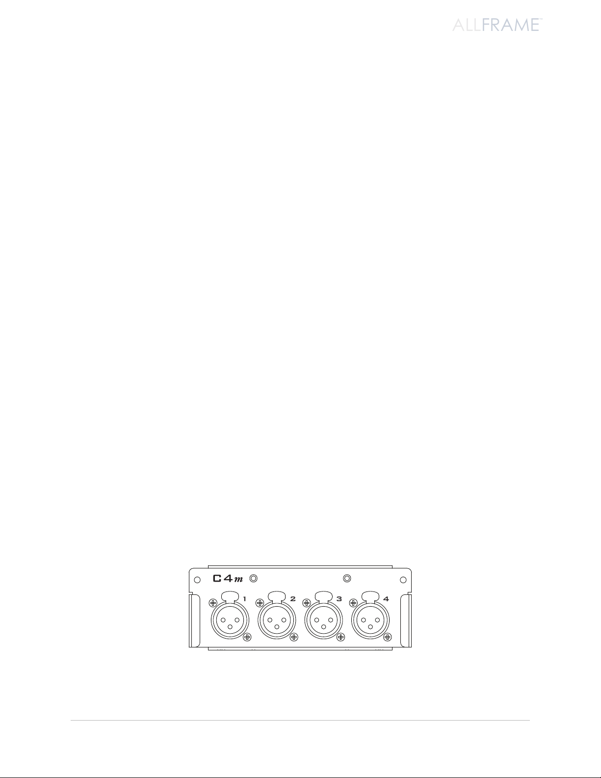
C4m Card
The C4m Mic/Line Input Card provides four remote-controllable analog mic- or line-level inputs per card. The
C4m mic preamp circuitry provides clean, transparent, archival quality sound without compromise.
State-of-the-art mic preamps •
Four XLR female inputs •
Remote controllable over the Pro64 network via hardware using the optional • RCI
Remote Control Interface and MCS Mic Control Surface
Remote controllable via software using Pro64 Network Manager •
Support for • m-control™ for Yamaha® digital consoles with the 6416Y2 A-Net Interface
Card installed
Mute, phase, low cut, 48V phantom power, and 24dB pad per channel•
The C4m card can be congured and installed by the user.
All channel strip settings can be saved as part of a Device Preset from Pro64 Network Manager.
ab o u T Yo u r Pr o 64 Pr o d u C T
2
Page 15
ALLFRAME
™
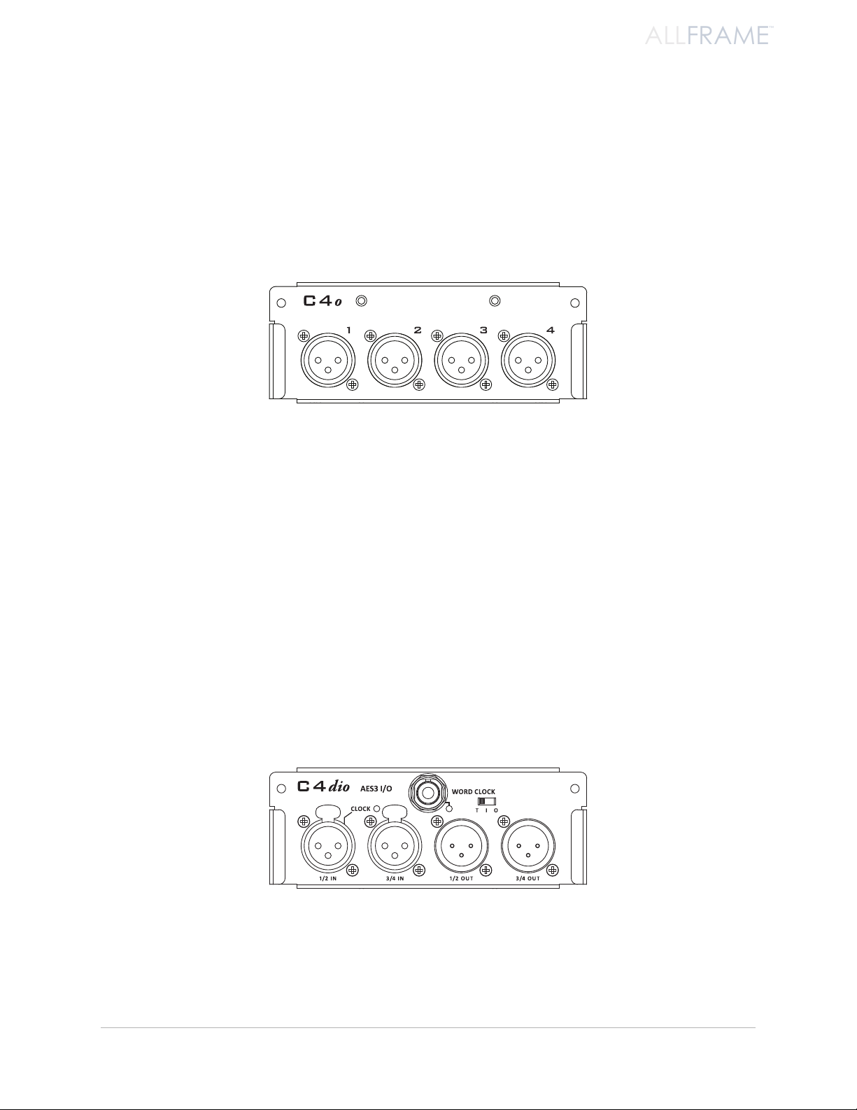
C4o Card
The C4o Output Card provides four XLR analog outputs with five variable output levels, controllable from the
Pro64 Network Manager application. Output Level settings (per channel) include:
+28 dB u•
+24dBu •
+18dBu •
+4dBu •
Mic •
The C4o card oer mic- or line-level output.
Output level settings (per channel) can be saved as part of a Device Preset from Pro64 Network Manager for quick
and easy recall of frequently used settings.
C4dio Card
The C4dio Digital I/O Card provides four AES3 digital inputs and four AES3 digital outputs per card. The C4dio
also allows external clocks to be used with a AllFrame device.
Four AES3 digital inputs; two XLR female jacks •
Four AES3 digital outputs; two XLR male jacks•
• Clock sync support for AES3 devices
External • Word Clock support with BNC jack
Configurable BNC clock jack can be set for: Input, • Input With Termination, or Output.
• Sample Rate Converters for external digital devices
The 4x4 C4dio card also oers external clocking options.
The card’s settings, including the sample rate converter’s on/off status per channel pair, can be saved as part of a
Device Preset from Pro64 Network Manager.
ab o u T Yo u r Pr o 64 Pr o d u C T
3
Page 16

ALLFRAME
™
Accessories
A number of accessories are available for the AllFrame Multi-Modular I/O System.
RK6 Rack Kit
The RK6 Rack Kit is a set of rack ears for mounting the F6 in a standard 19” equipment rack. With the RK6 attached,
the F6 requires 6U of space. See page 17.
SK6 Stage Kit
The SK6 Stage Kit allows the F6 to be mounted in a heavy-duty, protective steel case to provide extra protection
to the unit making it suitable for applications that require extra protection for the device, such as on-stage use.
See page 19.
LK4 Label Kit for C4m and C4o
The LK4 is a patchbay-style label kit for the C4m and C4o audio I/O cards for AllFrame. It attaches to the face plate
of the C4m or C4o card and allows custom printed labels to be added to the AllFrame I/O. The LK4 is not suitable
for use with the C4dio.
HK6 Security Hardware Kit for F6
The HK6 includes replacement hardware for making an AllFrame installation tamper resistant. The kit includes
tamper-resistant Torx® pin-head screws and a driver bit to replace the standard screws used for mounting the I/O
cards, fan tray, and access plate to the F6, as well as for mounting the F6.
Fan6 Replacement Fan Tray Assembly
The Fan6 Replacement Fan Tray Assembly is an exact replacement for the standard fan assembly in the F6. The
Fan6 provides quiet and reliable cooling for the F6, ensuring safe operation in ambient temperatures up to 50°C.
The Fan6 replacement fan tray for the F6 Modular I/O Frame can be installed by the user in the field.
PLT6-s Surface-Mount Finishing Plate for F6
The PLT6-s is an anodized aluminum plate that provides a clean finish for surface-mounted F6 Modular I/O Frames.
The F6 and PLT-s assembly attaches to a standard NEMA electrical box with just four screws.
PLT6-f Flush-Mount Finishing Plate for F6
The PLT6-f is an anodized aluminum plate that provides a clean finish for flush-mounted F6 Modular I/O Frames. It
attaches easily to the optional backing box used to hold the F6 with just four screws
ab o u T Yo u r Pr o 64 Pr o d u C T
4
Page 17
ALLFRAME
™
Power Supplies
It is important to note that the AllFrame system’s F6 Modular I/O Frame does not ship with a power supply. It is
the responsibility of the installer to provide an adequate power supply suitable for the application according to
the specifications listed later in this document. See page 23.
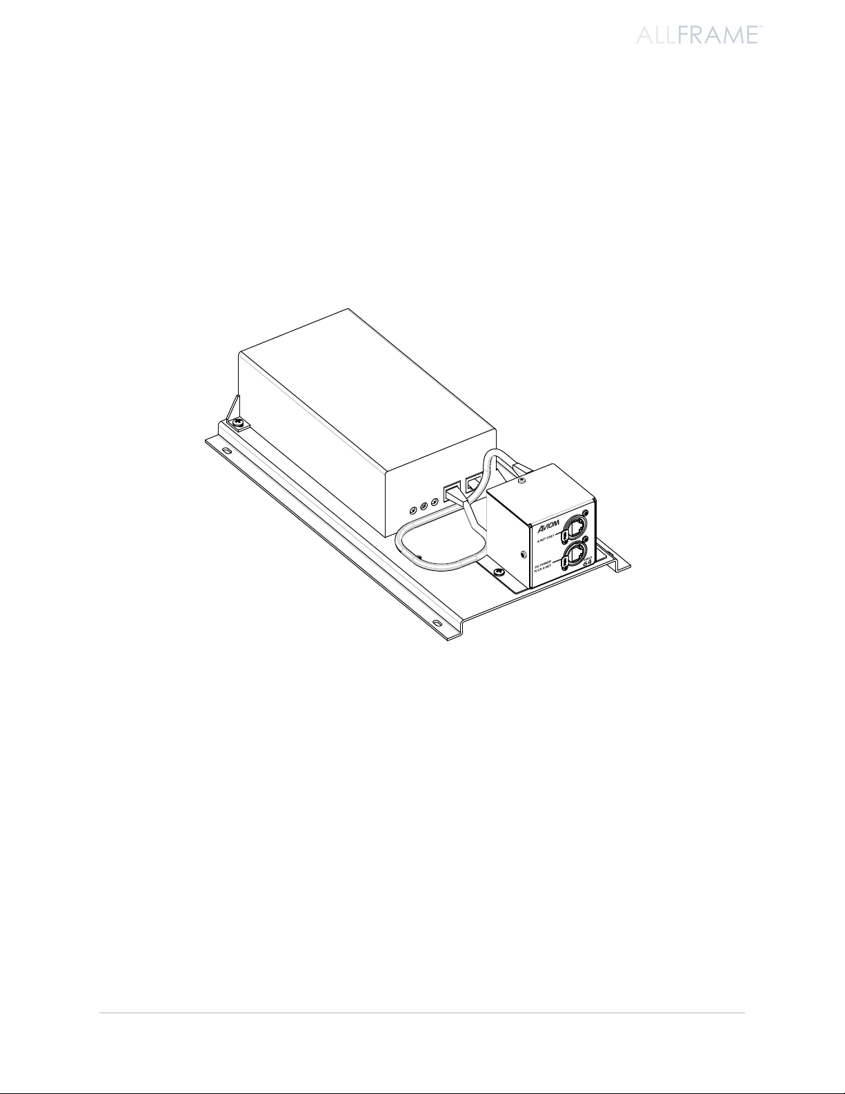
POA80 Power Over A-Net Power Supply
The POA80 is a Power Over A-Net (PoA) power supply for the F6. The POA80 allows an F6 to receive its Pro64
A-Net data and DC power over a single Cat-5e/Cat-6 cable. See page 26.
ab o u T Yo u r Pr o 64 Pr o d u C T
The POA80 allows an AllFrame to be powered over the Cat-5 cable.
5
Page 18
ALLFRAME
™
Ab o u t A-Ne t
Aviom’s A-Net® is the only networking technology conceived, designed, and optimized for managing and
distributing audio using ordinary Cat-5e cables (or fiber by adding fiber optic SFP transceivers to the AllFrame
F6 Modular I/O Frame or MH10f Merger Hub). As implemented in the Pro64® Series products, A-Net can transmit
up to 128 channels of uncompressed 24-bit audio with the reliability and fidelity of analog, and the power and
flexibility of a true digital network.
As implemented in the AllFrame Multi-Modular I/O System, Pro64 A-Net allows variable sample rates in two
ranges, 44.1/48kHz and 88.2/96kHz, with ultra-low latency, jitter, and wander. Pro64 devices can be connected in
any combination of serial (daisy-chain) or parallel (star) topologies. Cable runs between Pro64 devices can be up
to 400 feet (120 meters) on Cat-5e, and miles on fiber optics (with Aviom fiber-capable equipment).
Because A-Net is designed specifically for audio, the technological limitations of Ethernet and Ethernet-based
products are removed, while audio performance and system flexibility are increased. A-Net incorporates Aviom’s
unique patented and patent-pending algorithms for controlling clock jitter and wander, as well as system-wide
latency—regardless of an installation’s size, design, or clocking setup. A-Net offers significant advantages in
fidelity, performance, and flexibility over Ethernet-based products.
A-Net uses the “physical” layer of Ethernet, but it eliminates all the protocol elements that are designed for
computers and IT-style networking. In audio applications, these other layers reduce efficiency, impose system
restrictions, and introduce latency and timing instability. By eliminating Ethernet data structures, A-Net creates a
superior network with enhanced audio performance. With A-Net and the Pro64 Series, Aviom continues to break
new ground in the design and development of innovative digital audio networking technologies and solutions.
AllFrame Supported Sample Rates
Sample Rate Minimum Maximum
1x 44.1/48kHz 39.7kHz 52kHz
2x 88.2/96kHz 79.4kHz 104 kHz
Clocking
The Pro64 network offers the most flexible clocking and synchronization options in the industry even when
syncing to an external clock source.
Any Pro64 I/O device can be designated the Clock Master for the network, generating and distributing its internal
clock. Digital I/O devices are capable of syncing to and distributing an external clock from a Word Clock or AES3
source to the network.
Control Data
The Pro64 version of A-Net has built-in, dedicated bandwidth for 14 channels of non-audio control data through
the use of Aviom’s innovative Virtual Data Cables™. These data streams are always available to carry MIDI, RS-232,
RS-422, or GPIO (General Purpose I/O), and they never compete with the audio channels for network resources,
regardless of the system configuration. (Not all VDC data types are supported on every Pro64 device.)
ab o u T a-ne T
6
Page 19
ALLFRAME
™
Because VDC inputs are simply incorporated into the A-Net stream, these control signals can be transmitted over
DC Power 65w max
DC POWER
65W MAX
very long cable runs and even across an entire Pro64 network, significantly expanding the applications possible
with MIDI, RS-232/422, and GPIO.
It is important to note that although the AllFrame Multi-Modular I/O System does not have dedicated VDC I/O
connections on its hardware, all VDC control data that enters the network stream from other Pro64 devices is
retained in the A-Net stream for other devices to use. The control data is simply ignored by the AllFrame.
A-Net Ports
Pro64 I/O devices have dual A-Net ports, labeled A and B. Both ports carry a bidirectional A-Net stream at all
times. (That is, both ports are always transmitting and receiving A-Net data.)
The F6 Modular I/O Frame has both copper-based Cat-5e connections and fiber optic ports (that require optional
SFP transceivers). Each are labeled A and B. Any combination of the two types of ports can be used, but only two
A-Net ports may be active at any time.
Pro64’s Auto Mode provides a true audio network with 64 available “Slots” for transporting audio (at 44.1/48kHz).
Every audio Slot is available everywhere in the network, with no upstream/downstream restrictions. In Auto Mode,
there are no connection rules; devices can be connected in series, parallel, or combinations of series and parallel.
Connect a Cat-5e (or fiber) cable to either the A or B A-Net port and the system does the rest. No addressing or IT
configuration is required.
P No t e : Manual Mode is not supported on AllFrame devices.
Copper Cat-5e and ber optic A-Net por ts on the top panel of the F6
ab o u T a-ne T
7
Page 20
ALLFRAME
™
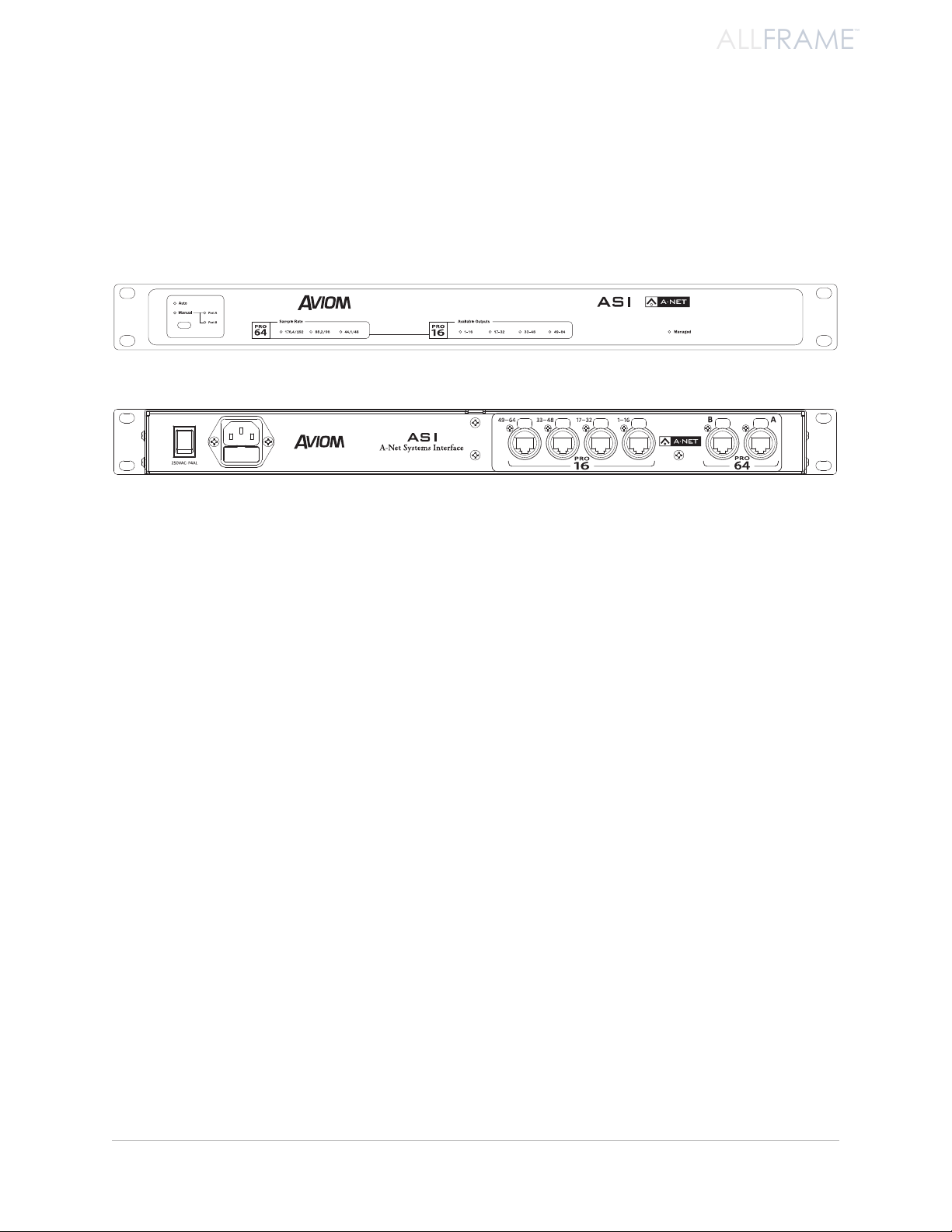
Support For Pro16 Series Products
Pro64 Series products can be combined with Pro16® Series output products such as the Pro16 Monitor Mixing
System by adding the Pro64 ASI A-Net Systems Interface. This 1U device converts Pro64 A-Net data to Pro16 data,
providing up to four streams of 16-channel data (depending on the Pro64 sample rate) that can be used with
A-16II and A-16R Personal Mixers, A-Net Distributors, and the AV-P2 and AN-16/o Output Modules.
Front and rear panels of the ASI A-Net Systems Interface
The ASI is not compatible with the A-Net output of Pro16 input devices such as the AN-16/i, AN-16/i-M, the Y1
console interface card (for Yamaha® digital products), and A-Net console cards built by third-party manufacturers
for their digital console products.
ab o u T a-ne T
8
Page 21

Fi r m W A r e No t i c e
All Pro64 devices in a network should be updated to use the most recent firmware version to ensure
trouble-free operation.
As new Pro64 devices are released, older Pro64 products need to be updated so that they recognize the features
and functions of the newer modules—something that is especially important if one of the older devices will be
used as the network’s Control Master.
Pro64 Network Manager is a free Windows software application designed for editing and managing your Pro64
devices; it also includes a built-in utility for updating the firmware in Pro64 Series products. The current version of
Pro64 Network Manager can be downloaded from the Aviom website.
P No t e : AllFrame devices in a Pro64 network require the Pro64 Network Manager application for all I/O routing
and channel programming. There is no front panel user interface.
Pro64 Network Manager requires a direct RS-232 (serial) connection between the computer and the Control
Master device on the Pro64 network. Normally this is accomplished by connecting a null modem DB9 cable
between the RS-232 jack on the computer and the Pro64 device. Complete information on using RS-232 (and
USB-to-RS-232 adapters) is available on the Aviom website. Updates take just a few minutes per module.
The AllFrame F6 Modular I/O Frame includes a USB connector on its front panel for connecting a computer when
the device is used as the network’s Control Master. No DB9 RS-232 cable is required when using the F6 as a Control
Master.
Pro64 Network Manager is designed to run on a PC under Microsoft® Windows® XP, Vista, or Windows 7. There
is no official Apple Mac support. However, Mac users can run Pro64 Network Manager using Windows running
under Apple’s Boot Camp or Parallels programs on Intel-based Macs.
Get Pro64 Network Manager and firmware update files from the Aviom website, http://www.aviom.com.
fi r m w a r e no T i C e
9
Page 22
ALLFRAME
™
As s e m b l i N g t h e Al l Fr A m e sy s t e m
The AllFrame Multi-Modular I/O System is user-configurable, and is designed to be easy to modify and reconfigure
as your needs change.
Prior to installing the unit in an electrical wall box, equipment rack, or other enclosure, the user must connect
the mounting brackets, install I/O cards, configure the power options for the F6 Modular I/O Frame, and provide
Pro64 A-Net via Cat-5/Cat-6 or fiber.
Once the F6 is assembled and connected to the network, you can apply power to the device and start to manage
the network using Pro64 Network Manager.
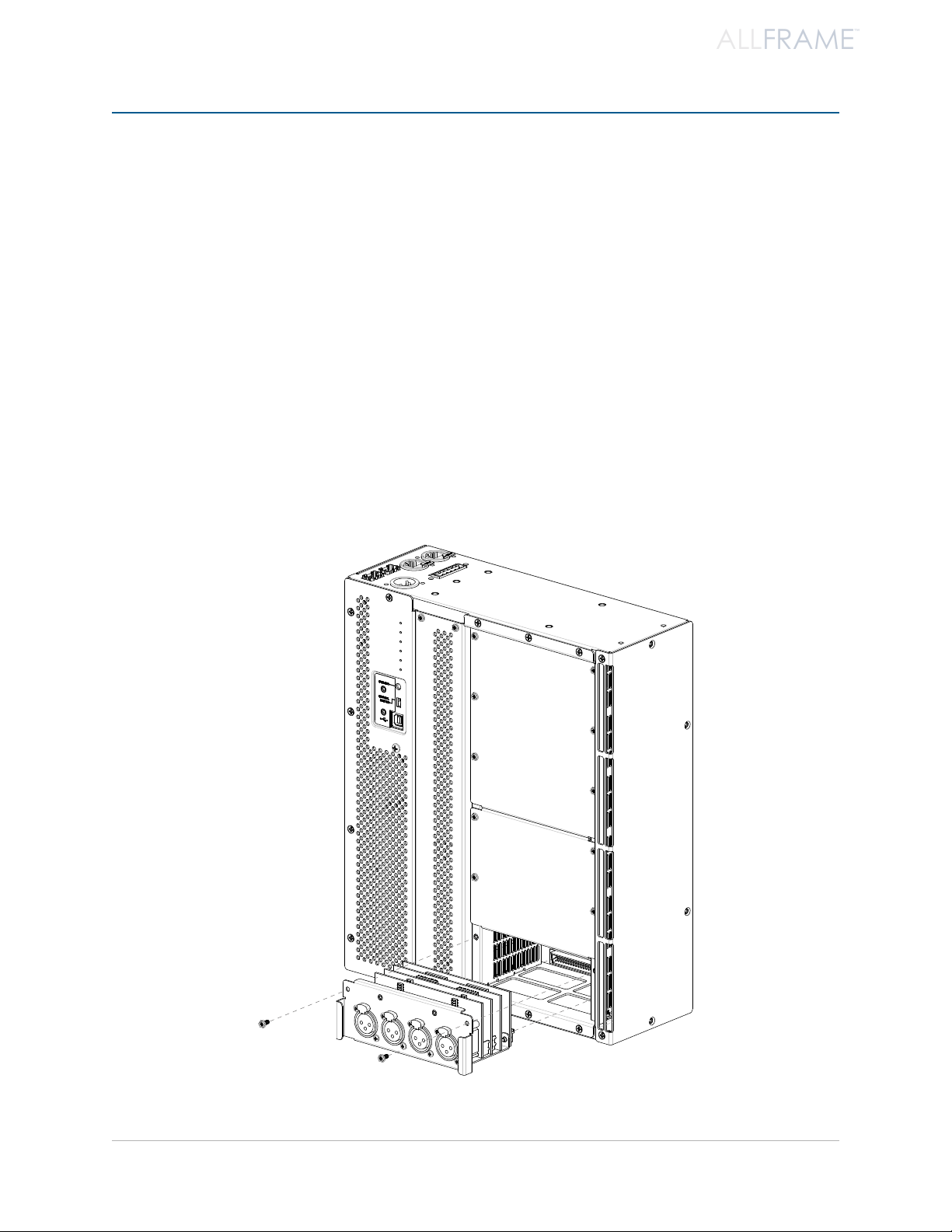
Installing I/O Cards
The F6 Modular I/O Frame has six I/O card slots that can be configured by the user to contain any combination of
analog and/or digital I/O cards. The I/O cards can be installed in any order and into any of the six available slots
(labeled A through F) in the F6. Cards can be installed using only a Phillips screwdriver or nut driver.
as s e m b l i n g T h e al l fr a m e sY s T e m
Installing an I/O card in the F6
10
Page 23
ALLFRAME
™
To install an I/O card in an F6 card slot:
Start with all power to the F6 Modular I/O Frame off. 1.
Do not remove or install I/O cards while the F6 is powered on.
Place the F6 on a clean, level work surface with the I/O slots facing up. 2.
Use a size #1 Phillips screwdriver or 3/16-inch 3. hex nut driver to remove the screws that hold
the card slot’s cover plate in place.
Retain the blank 4. cover plates that ship with the F6 Modular I/O Frame for future use; they
will help protect the I/O connectors and keep dust out of the F6 unit.
Remove the I/O card from its packaging. 5.
Align the multi-pin connector on the rear of the I/O card with the matching connector on 6.
the F6 Modular I/O Frame.
Press firmly on the I/O card, applying firm, even pressure enough to seat the card in its 7.
backplane connector on the F6.
Reattach the two screws removed from the cover plate to secure the card to the F6 unit. * 8.
Repeat this procedure for any remaining I/O cards to be installed. 9.
P No t e : Always secure all installed I/O cards using the screws provided before transporting the F6.
* The optional HK6 Security Hardware Kit for F6 can be used instead of the standard screws if additional security
is required for an installation.
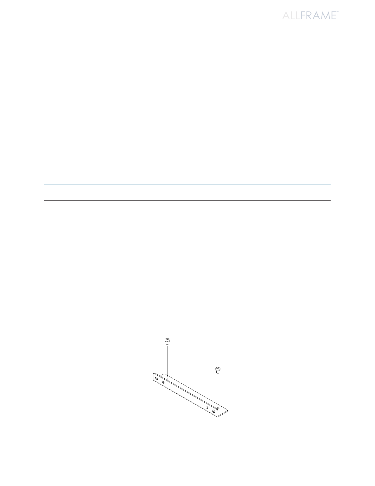
Installing the F6 Mounting Brackets
The F6 Modular I/O Frame ships with a pair of right angle mounting brackets that can be used to attach the F6 to
a flush-mount or surface-mount plate when the device is installed into an electrical box, floor pocket, stage box,
etc. The brackets attach to the F6 with a pair of screws; only a Phillips screwdriver is required for installation. Each
bracket also has two threaded inserts designed to accept size 8-32 bolts when mounting the assembled F6 to a
wall plate. (The brackets are not required for rack-mount installations.)
For maximum installation flexibility, the brackets can be installed flush with either the front or rear face of the
F6 Modular I/O Frame. If desired, the brackets can also be used to secure the F6 directly to a wall or other solid
surface without a surrounding electric box.
The F6 mounting bracket attaches with two screws to the F6.
as s e m b l i n g T h e al l fr a m e sY s T e m
11
Page 24
ALLFRAME
™
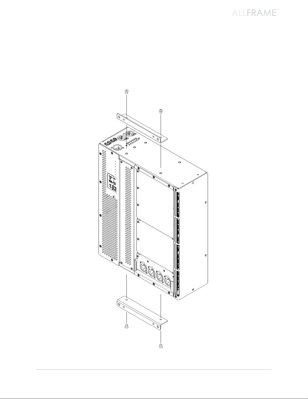
To install the mounting brackets:
Place the F6 on a clean, level work surface. 1.
Align the non-threaded holes in the bracket with the threaded holes in either the front or 2.
rear mount positions in the top panel of the F6.
Install the included Phillips screws through the holes in the bracket and into the F6, 3.
tightening them securely.
Repeat for the remaining bracket on the bottom panel of the F6. 4.
as s e m b l i n g T h e al l fr a m e sY s T e m
Attach the mounting brackets to the F6 Modular I/O Frame with the screws provided
12
Page 25
ALLFRAME
™
Installing SFP Fiber Transceivers
There are two sets of A-Net ports on the top face of the F6—two copper (Cat-5e, Cat-6) ports and two 100 Mbps
fiber optic ports (requires optional SFP transceivers not included with the F6). Only two A-Net ports can be active
at a time; these can be mixed and matched in any of the four combinations shown below:
A-Net Port A A-Net Port B
Cat-5e Cat-5e
Cat-5e Fiber
Fiber Cat-5e
Fiber Fiber
P No t e : Always power down the F6 Modular I/O Frame before installing or removing SFP transceivers.
The F6 only checks for installed SFP transceivers at power-up. Any A-Net port (A or B) with an SFP installed will
have its corresponding copper Cat-5 port disabled. When the F6 Modular I/O Frame detects an installed SFP
transceiver at power-up, it places the corresponding copper port and its PHY chip in a lower power state, even if
no fiber cables are connected.
Though it can’t be used for a Pro64 network connection, the AllFrame can be powered through A-Net port B
when an SFP transceiver is installed in port B.
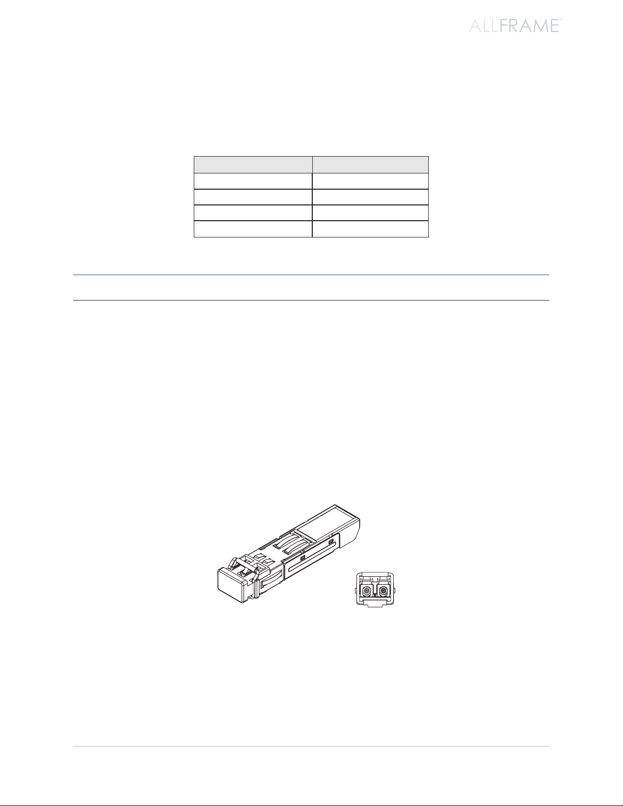
SFP Transceivers
Small form-factor pluggable (SFP) is a specification for a series of modular, physically compact optical transceivers.
The two 100 Mbps SFP format fiber optic ports on the F6 Modular I/O Frame allow the user to connect optional
single-mode or multi-mode fiber optic transceivers that can transmit Pro64 A-Net data over longer distances
than Cat-5 based cabling can provide.
The SFP ber optic transceiver is shown with its dust cap on (left) and from the front (right) with its transmit and receive
connectors exposed.
When connecting Pro64 devices via fiber, always use the same type of SFP transceiver in each unit—for example,
use a 100 Mbps single-mode SFP transceiver with the same light wavelength specifications in each device. You
cannot connect a multi-mode fiber transceiver to a single-mode transceiver.
Always leave the optical transceiver’s dust cap on when the SFP transceiver is not in use to avoid damage to the
internal optical connections.
as s e m b l i n g T h e al l fr a m e sY s T e m
13
Page 26
ALLFRAME
™
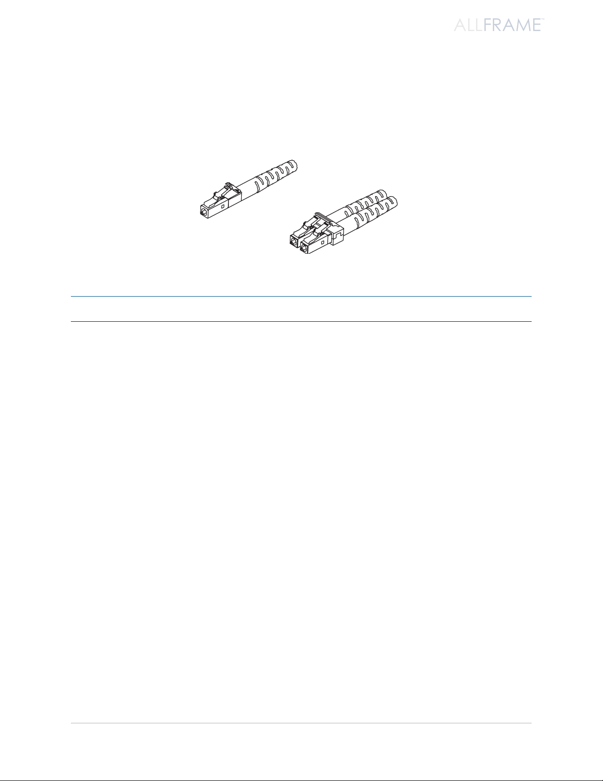
LC Connectors
SFP transceivers typically use a connector known as LC. For bidirectional transmission, two fiber cables per SFP
transceiver are required, one to transmit and the other to receive. The SFP transceiver can accept single (simplex)
or dual (duplex) type connectors. Aviom suggests using duplex connectors with Pro64 devices to avoid transmit/
receive errors caused by the connection/removal of individual fiber cables.
A simplex LC connector (lef t) and a duplex connector (right).
P No t e : Do not operate the F6 with only one fiber cable connected to the SFP transceiver.
Cat-5e Cables
All Cat-5e connections between A-Net devices should use Unshielded Twisted Pair (UTP) cable. The cable can be
of the stranded or solid type; solid wire performs better over long distances while stranded wire is more flexible
and easier to manipulate and therefore easier to work with in a performance situation.
Cables designated as Cat-5e in Pro64 documentation can be interchanged with any Cat-6 (or better) cable. Cables
will be referred to simply as “Cat-5e.” For best long distance performance, use Cat-6 cabling. Remember, all
cables are not created equally. Distance performance will be impacted by numerous factors including cable build
quality, the type of wire used to make the cable (solid core or stranded), connector quality, the number of splice
points (such as patch bay interconnect points), and the preservation of the cable’s twisted wire pairs.
Connectors on Cat-5e cables can be of the standard RJ45 variety or of the locking Neutrik EtherCon type.
as s e m b l i n g T h e al l fr a m e sY s T e m
14
Page 27

ALLFRAME
™
EtherCon Connector
Pro64 Series products feature locking connectors for all network I/O. The Neutrik® EtherCon connector is a dual
RJ45-type connector that can receive a standard Cat-5e or Cat-6 cable or a cable fitted with the special locking
EtherCon connector.
When using a standard Cat-5e or Cat-6 cable, plug the cable into the center of the EtherCon jack; release the cable
by pressing on the small plastic tab built into the cable connector.
The EtherCon panel-mount jack
The locking EtherCon connector is similar to an XLR plug, the kind commonly used on microphone cables. Insert
an EtherCon-equipped cable into the jack until it clicks and locks in place. To remove the cable, press on the metal
release tab at the top of the panel-mounted EtherCon jack and pull the connector outward.
P No t e : Neutrik also makes a Cat-6 EtherCon connector. It is a different size than their Cat-5 connector and will
not fit into the Cat-5 EtherCon jacks used on the F6.
as s e m b l i n g T h e al l fr a m e sY s T e m
15
Page 28
ALLFRAME
™
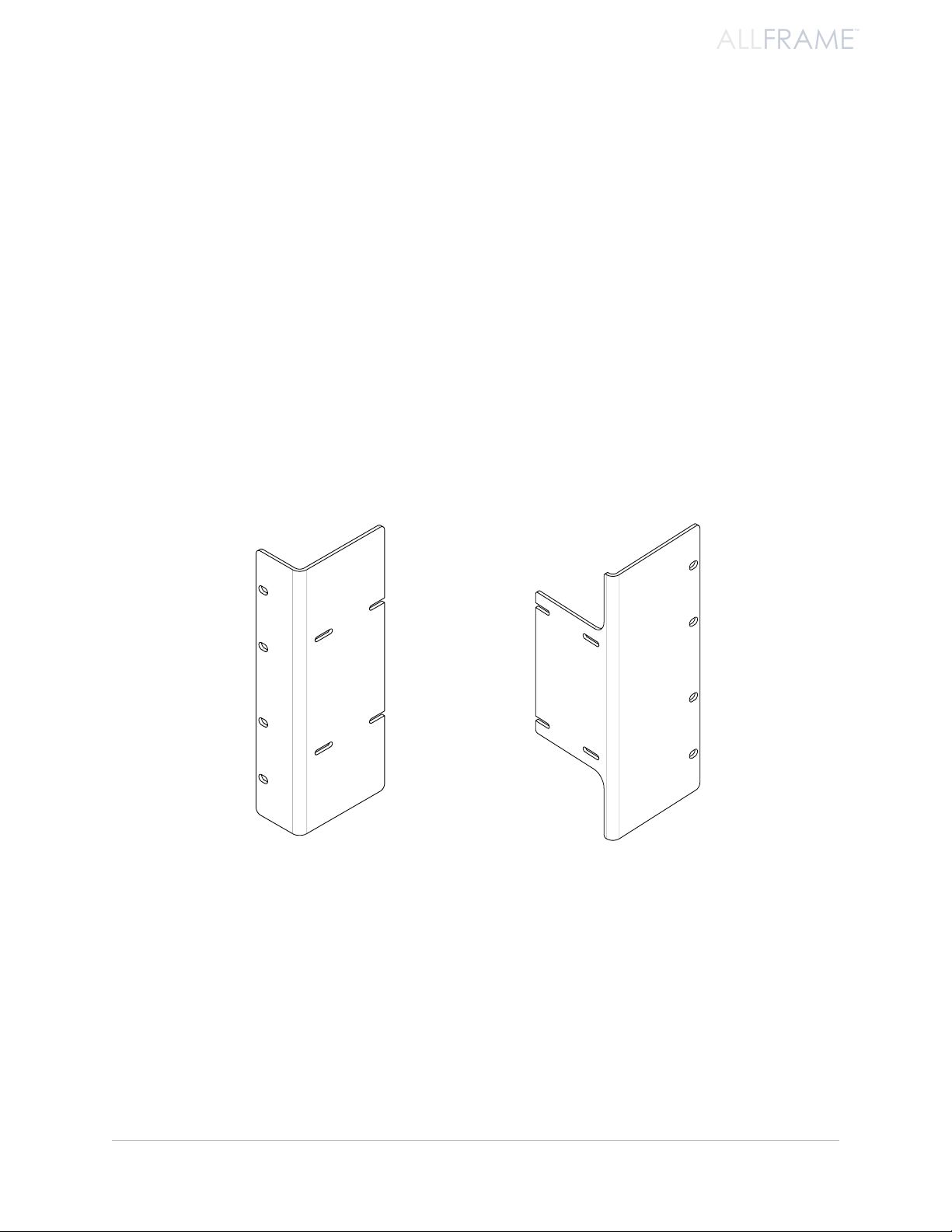
RK6 Rack Kit
The optional RK6 Rack Kit It can be mounted to an F6 Modular I/O Frame using only a Phillips head screwdriver.
The kit allows the F6 to be mounted with the rack ears facing either the front or rear of the product.
The RK6 kit includes individual left and right rack ears, plus the 8 screws required to secure the rack ears to the
sides of the product. The right-side rack ear has special cutouts to allow it to clear the connectors on the F6 body.
The mounting brackets that ship with the F6 are not required for rack-mount installation. Remove them prior to
installing the F6 in an equipment rack if they have been previously installed.
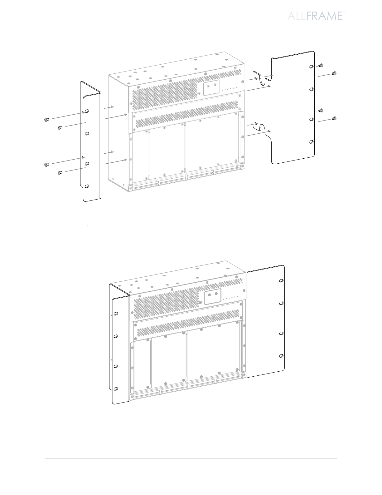
Installing the RK6
To mount he RK6 kit on an F6 Modular I/O Frame:
Place the F6 Modular I/O Frame on a clean work surface. 1.
Align the left rack ear with the holes in the F6 case.2.
Attach the four screws to secure the left rack ear.3.
Repeat this procedure for the right side rack ear. 4.
The F6 Modular I/O Frame is now ready to be mounted into any standard 19” rack or case. Always use four rack
mount screws per side when mounting the F6 in an equipment rack. The use of nylon washers between the rack
screws and the F6 is suggested to avoid marring the finish on the product’s rack ears.
as s e m b l i n g T h e al l fr a m e sY s T e m
Rack ears for the F6 can be mounted facing the front or rear of the device.
16
Page 29
ALLFRAME
™
The F6 is shown with the rack ears facing the front and ready to be installed.
as s e m b l i n g T h e al l fr a m e sY s T e m
The F6 shown with optional rack ears attached
17
Page 30
ALLFRAME
™
SK6 Stage Kit
The SK6 Stage Kit is designed as a protective stage box for an F6 Modular I/O Frame, part of the AllFrame system
of modular I/O products. The SK6 Stage Kit also provides shock mount protection for the assembly when an
AllFrame is transported or used on stage as a drop box.
The kit includes the protective metal case with shock mount foam, a replacement ventilation panel, plus the
screws required to secure the SK6 Stage Kit components. A Phillips screwdriver is required for assembly.
Installing the SK6
Remove the Original Side Ventilation Panel:
Place the F6 Modular I/O Frame with its front face up on a clean work surface. 1.
Remove the L-shaped 2. mounting brackets from the top and bottom of the F6 if they were
installed for a previous application .
Remove the two Phillips screws from the top face of the side ventilation panel of the F6 3. .
Remove the four screws from the side panel of the ventilation panel 4. .
Set the ventilation panel aside. (The screws will be reused in the following steps.) 5.
Remove the side ventilation panel and any previously installed mounting brackets.
P No t e : Save the original side ventilation panel for future use in case the F6 is installed in a different type of
enclosure. The design of the ventilation panel is an integral part of the F6 cooling system.
as s e m b l i n g T h e al l fr a m e sY s T e m
18
Page 31

ALLFRAME
™
Install the SK6 Side Ventilation Panel:
Align the replacement SK6 side ventilation panel with the side of the F6.1.
Install two screws through the holes in the ventilation panel into the top of the F6 2. .
Install the four screws that secure the side of the ventilation panel 3. .
Tighten all six screws.4.
Place the Completed F6 into the Stage Kit:
Orient the SK6 case so that the opening for the network connections 1. is aligned as
shown in the diagram.
Slide the F6 into the SK6 case from the top down (to allow the EtherCon connectors clear 2.
the foam) until it fits snugly against the foam shock mounts on all sides .
Install the new ventilation panel.
as s e m b l i n g T h e al l fr a m e sY s T e m
Place the F6 into the SK6 case, oriented as shown.
19
Page 32

ALLFRAME
™
Install the Stage Kit Cover:
Carefully align the stage kit cover panel as shown 1. . Be sure that the tabs on the sides of
the cover panel are on the inside of the case.
Install the two screws to hold the side panel in place 2. .
Install three screws in the both the left and right sides of the stage kit 3. .
Finally, install the three screws to secure the top panel 4. .
Secure the top of the stage kit with the screws provided.
as s e m b l i n g T h e al l fr a m e sY s T e m
20
Page 33

ALLFRAME
™
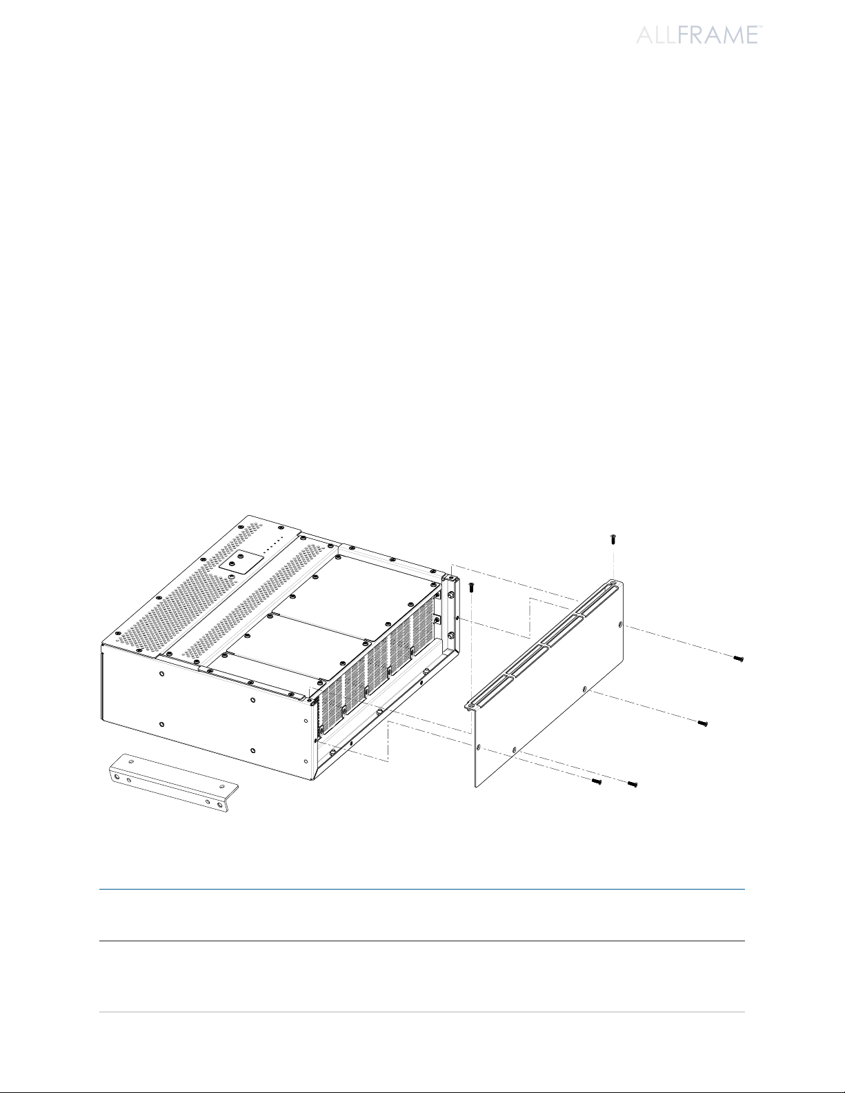
Install the Connector Cover:
The SK6 Stage Kit ships with an optional connector cover plate that can be added to provide extra protection to
cables connected to the I/O section of the F6 when it is installed in a stage kit. The cover plate can be installed
on either side of the I/O section. The angled flange on the plate should be oriented as shown for maximum cable
protection.
The optional cover plate can be installed on either side of the I/O section.
as s e m b l i n g T h e al l fr a m e sY s T e m
21
Page 34

ALLFRAME
™
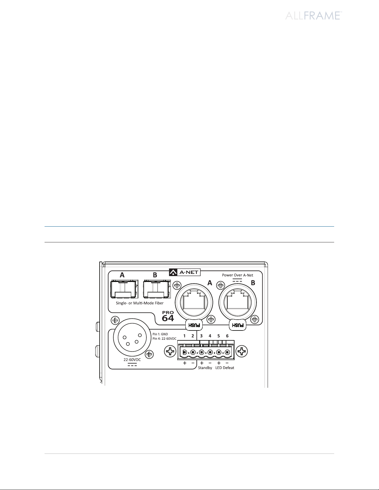
Po W e r i N g t h e F6 mo d u l A r i/o Fr A m e
DC Power 65w max
DC POWER
65W MAX
The F6 Modular I/O Frame is a DC-powered device that can be powered in a variety of ways:
Via the • 4-pin XLR connector on the F6 top panel
Via the 2-pin • Euroblock connector on the F6 top panel
Over the • A-Net cable using an approved Power Over A-Net (PoA) power supply such as the
Aviom POA80 connected to A-Net Port B
All three DC power sources can be connected at the same time to provide power source redundancy without
harming the F6 Modular I/O Frame.
P No t e : The F6 Modular I/O Frame does not ship with a power supply. It is the installer’s responsibility to
provide a power source best suited for the application where the AllFrame products will be used.
DC Power to the F6 Modular I/O Frame can be supplied through the 4-pin XLR (1), the Euroblock terminals #1-2 (2), and/or over
the A-Net cable using the A-Net B port (3).
Po w e r i n g T h e al l fr a m e
22
Page 35

ALLFRAME
™
Po W e r sA F e t y WA r N i N g s
Please heed the following warnings related to the various types of power supplies that can be used with the F6
Modular I/O Frame.
For Power Over A-Net
When powered through the copper (Cat-5) A-Net Port B connector, the F6 Modular I/O Frame shall be connected to an
Aviom POA80 power supply, a UL60950-1 Certified/Listed ITE power supply having a SELV (Safety Extra Low Voltage)
rated output.
No other power supply should be connected to this A-Net port.
Turn off the POA80 power supply before removing or patching any Cat-5 connections.
For DC Power via the XLR or Euroblock
When powered through the Euroblock terminal block or 4-pin XLR connectors, the F6 Modular I/O Frame shall be
connected to a UL60950-1 Certified/Listed ITE power supply having a SELV (Safety Extra Low Voltage) rated output
voltage between 22 and 60V DC. To guarantee proper startup, this supply should be rated for at least 100 watts.
System Connections
The copper (RJ45) and fiber A-Net ports can both be used for intra-building connections. Any inter-building
connections should only be made using the fiber ports.
Po w e r i n g T h e al l fr a m e
23
Page 36

ALLFRAME
™
Power Supply Requirements
DC Power supplies used with the F6 and connected to the Euroblock terminal connector or the 4-pin XLR jack
must meet the following requirements:
Power Supply Rating Requires a UL60950-1 Certified/Listed ITE power
supply having a SELV (Safety Extra Low Voltage) rated
output voltage between 30 and 60V DC
Voltage
(measured at the input of the
F6 Modular I/O Frame)
Maximum Current
(varies with input voltage)
(voltage at the input of the F6
Modular I/O Frame)
P No t e : When powering the F6 Modular I/O Frame through the Euroblock or 4-pin XLR input with a switching
power supply, an in-line EMI filter may be needed to meet the conducted emissions requirements of
EN 55103-1 and FCC Class B. This filter is not required when the unit is powered by a linear supply.
30-60VDC, inclusive of tolerance
1.08A @ 60V
1.16A @ 56V
1.35A @ 48V
1.41A @ 44V
2.70A @ 24V
2.95A @ 22V
Power Cable Lengths
Maximum usable distances for DC power cables used with the F6 and connected to the 4-pin XLR or Euroblock
terminal block connectors will vary based on the gauge of the wire, and the voltage and power rating of the
supply. The cable will dissipate some of the power as heat resulting in a voltage drop on the cable that increases
with cable length.
The following table presents power cable length as a function of wire gauge and supply voltage/power rating.
Maximum Cable Distance For Various Power Supplies
Wire Gauge 24V, +/-5% @ 100 Watts 48V, +/-5% @ 100 Watts 48V, +/-5% @ 120 Watts
12 75 feet, 23 meters 900 feet, 274 meters 1800 feet, 548.5 meters
14 48 feet, 15 meters 550 feet, 168 meters 1150 feet, 350.5 meters
16 30 feet, 9 meters 450 feet, 137 meters 725 feet, 221 meters
18 18 feet, 5.5 meters 300 feet, 91.5 meters 450 feet, 137 meters
Power Dissipation
Of Cable
2.4 Watts 8 Watts 20 Watts
Po w e r i n g T h e al l fr a m e
24
Page 37

ALLFRAME
™
Power Over A-Net (PoA)
To use Power Over A-Net with the F6 Modular I/O Frame, the Aviom POA80 power supply is required. This power
supply has been tested and approved for use with the F6 Modular I/O Frame.
Power Over A-Net only works with A-Net Port B on the F6 I/O Frame. Do not connect any other power supply to
the A-Net inputs of the F6.
The POA80 power supply accepts one EtherCon RJ45 Cat-5e or Cat-6 A-Net input coming from a Pro64 device
and outputs the Pro64 A-Net data plus the DC voltage required to power the F6 Modular I/O Frame.
When using the F6 Modular I/O Frame with an approved Power Over A-Net (PoA) power supplies, DO NOT
patch the Cat-5 connection between the Power Over A-Net (PoA) device and the F6 Modular I/O Frame
unit with power applied. Power down the (PoA) power supply first and wait until all of its LED indicators
are off.
Connecting the POA80 Power Supply
Follow these steps to connect a POA80 Power Over A-Net (PoA) power supply to the F6 Modular I/O Frame:
Make sure that the POA80 power supply is disconnected from the AC power source.1.
Power down the Pro64 source device that will feed the A-Net data to the POA80 power 2.
supply.
Connect a Cat-5e/Cat-6 cable between either A-Net port on the source Pro64 device to the 3.
A-Ne t ON l y port on the POA80 power supply.
Connect another Cat-5e from the POA80 power supply’s RJ45 4. DC PO w e r Pl u s A-Ne t port
to the A-Ne t B port on the F6 Modular I/O Frame.
It is now safe to power up the POA80 power supply and the network’s Pro64 devices. 5.
Connect A-Net coming from the Pro64 network to the A-Ne t ON l y port of the POA80 power supply. Connect another cable
from the DC PO w e r Pl u s A-Ne t port of the power supply to A-Ne t B port on the F6.
Po w e r i n g T h e al l fr a m e
From
Pro64
device
To F6 A-Net Port B
25
Page 38

ALLFRAME
™
P No t e : Do not connect a Power Over A-Net cable from the POA80 to the A-Ne t A port on the F6 or to the
DC Power 65w max
DC POWER
65W MAX
3.038 in.,
77.21 mm
13.25 in.,
336.55 mm
7.000 in.,
177.80 mm
13.25 in.,
336.55 mm
13.25 in.,
336.55 mm
7.000 in.,
177.80 mm
3.038 in.,
77.21 mm
A-Net ports on any other Pro64 device.
Connect Power Over A-Net cables only to the A-Net B port on the F6.
Mounting the POA80
The POA80 can be mounted on both horizontal and vertical surfaces. However, do not mount the POA80
horizontally on a vertical surface such as a wall or interior of a rack, and do not mount the POA80 upside down.
Do not mount a POA80 upside down or horizontally on a wall.
Po w e r i n g T h e al l fr a m e
These orientations allow for proper ventilation of the POA80.
26
Page 39

ALLFRAME
™
DC Power via the 4-Pin XLR
2
1
4
3
DC Power 65w max
DC POWER
65W MAX
Power for the F6 Modular I/O Frame can be supplied via the 4-pin XLR connector on the top panel of the F6. Refer
to the Power Supply Requirements on page 25 for more information.
The 4-pin XLR male plug
The 4-pin XLR jack providing power to the F6 should be wired as seen in the table below.
Connector Type 4-pin XLR
Pinout Pin 1: Ground
Pin 2/3: No Connect
Pin 4: 30-60VDC
Po w e r i n g T h e al l fr a m e
Connect DC power to the 4-pin XLR input on the F6.
27
Page 40

ALLFRAME
™
DC Power via the Euroblock Connectors
On the top panel of the F6, terminals 1 and 2 of the 6-pin Euroblock terminal connector can be used when
connecting a DC power supply. See the Power Supply Requirements on page 25 for more information about
selecting a properly sized power supply.
The terminal block connector connected to the F6 should be wired as seen in the table below.
Connector Type 2-pin terminal block
Pinout Pin 1: 30-60VDC (+)
Pin 2: Ground (-)
Terminal Blocks Phoenix Contact part number 17 54 44 9
Size: 5mm; 2 contacts per unit
Use a small screwdriver to secure the power supply wires to the terminal block.
To connect a power supply to the terminal block connector:
Carefully remove a small amount (about 1/4-inch, 6mm) of the insulation from each of the 1.
power supply’s wires.
Optionally, tin the ends of each bare wire with solder. 2.
Insert the positive 30-60VDC (+) wire into the 3. Pi N 1 (left) opening in the terminal block.
Secure the wire into place by tightening the screw on the top of the terminal block using a 4.
small screwdriver.
Insert the ground (-) wire into the 5. Pi N 2 (right) opening in the terminal block and secure it
in place by tightening the screw.
Install the terminal block into connectors 1-2 on the top of the F6, pressing the connector 6.
firmly in place.
P No t e : Do not connect DC power to any terminal block except #1-2 on the top of the F6 frame.
Po w e r i n g T h e al l fr a m e
28
Page 41

ALLFRAME
™
DC Power 65w max
DC POWER
65W MAX
Press the assembled power supply connector rmly into place.
To remove the terminal block from the mating connector, pull the plug assembly straight up; do not twist the
terminal block connector.
Po w e r i n g T h e al l fr a m e
29
Page 42

ALLFRAME
™
Pr o 64 us e r iN t e r F A c e
This section outlines the basic concepts of operation for Pro64 products. Pro64 I/O devices have some common
user interface elements that make setting up an audio network easy to understand.
Common elements include:
• A-Net Slot selection
• Sample Rate
Managed operation via • Pro64 Network Manager software
In addition, each I/O device in a Pro64 network has the ability to be set as the Control Master and/or Clock Master
(depending on the actual makeup of the analog/digital devices in the audio network). Only one device can have
control of these functions at a time in a properly configured Pro64 network.
A-Net Slot
Pro64 I/O devices come in a variety of configurations. To allow a large number of hardware audio input devices
to be available to the Pro64 audio network, Aviom has implemented the concept of the A-Net Slot to simplify the
configuration of potentially complex audio networks.
A Pro64 audio network will always have a finite number of A-Net Slots available that can be addressed by an
unlimited number of hardware channels. The actual number of available Slots is determined by the current
sample rate.
Slots versus Channels
You might be wondering why Aviom chose to refer to the audio I/O resources in the Pro64 Series products as
‘’slots.” Why not just call them “channels”?
We did this to avoid confusion between references to hardware audio resources and network audio resources. The
word ‘’channel’’ is ambiguous and may cause confusion when configuring an audio network. “Channel” appears
in many contexts, including audio mixing consoles, mic preamps, DSP processors, and DAW software.
We use the word ‘’channel’’ when referring to the physical audio inputs—analog or digital—on a piece of hardware
(such as the mic/line XLR input jacks on the C4m Mic Input Module used with the F6 in an AllFrame system). Each
of these audio inputs can be made active and added to the network individually, and it is only when activated
that they use any network resources (the A-Net Slots). To enable this powerful feature, Pro64 products separate
the hardware input and output resources from the available network resources, allowing each hardware input
channel to be added to the network as needed.
It is these activated hardware resources that are being referred to as “Slots.” Pro64 audio networks can potentially
have a greater number of audio channels and hardware I/O devices connected than the network can make
use of at one time. This provides flexibility without requiring constant re-patching or complicated computer
programming.
Keep in mind that a Pro64 A-Net network can only manage a specific number of Slots at a time, and this number
varies with the sample rate being used. The maximums when incorporating AllFrame devices are 64 Slots at the
48kHz sampling rate and 32 Slots at 96kHz.
Pr o 64 us e r in T e r f a C e
30
Page 43

ALLFRAME
™
In summary, think of “channels” as hardware resources that can be added to the network as needed and “Slots” as
locations within the digital audio network pipeline that A-Net uses to move data throughout the network.
A-Net Slot Example
The following example shows the power of the Pro64 network and the A-Net Slots concept. The range of A-Net
Slots used in the example has been limited to a group of 16 inputs for simplicity.
This graphic below represents a 16-channel Pro64 product; its hardware input channels can be assigned to the
network’s Slots by activating them individually.
Channel
1 2 3 4 5 6 7 8 9 10 11 12 13 14 15 16
For the example system, one 16-channel Pro64 input device is placed in each of four rooms of a production
facility, designated as Locations A, B, C, and D. One 16-channel output device is installed in the facility’s Location
E. All devices are set to operate within the same Slot range, 1-16.
Location A Inputs
Channel
1 2 3 4 5 6 7 8 9 10 11 12 13 14 15 16
Location B Inputs
Channel
1 2 3 4 5 6 7 8 9 10 11 12 13 14 15 16
Location C Inputs
Channel
1 2 3 4 5 6 7 8 9 10 11 12 13 14 15 16
Location D Inputs
Channel
1 2 3 4 5 6 7 8 9 10 11 12 13 14 15 16
Location E Outputs
Channel
1 2 3 4 5 6 7 8 9 10 11 12 13 14 15 16
Pr o 64 us e r in T e r f a C e
31
Page 44

ALLFRAME
™
By activating a group of channels on each of the four input devices, a total of sixteen inputs are used (indicated
by reverse text). All of these inputs are available on the network at every Pro64 output device. The operator in
Location E can use the sixteen inputs from Locations A, B, C, and D simultaneously.
The order in which the Pro64 devices are connected is irrelevant.
Location A Inputs
Channel
1 2 3 4 5 6 7 8 9 10 11 12 13 14 15 16
Location B Inputs
Channel
1 2 3 4 5 6 7 8 9 10 11 12 13 14 15 16
Location C Inputs
Channel
1 2 3 4 5 6 7 8 9 10 11 12 13 14 15 16
Location D Inputs
Channel
1 2 3 4 5 6 7 8 9 10 11 12 13 14 15 16
Location E Outputs
Channel
1 2 3 4 5 6 7 8 9 10 11 12 13 14 15 16
This makeup of this network can be reconfigured simply by activating a different set of channels. The input
devices can come from any combination Pro64 devices as well as any mix of signals types such as line-level, miclevel, digital, or those derived from Yamaha format console cards.
Slots and Sample Rate
The current network-wide sample rate will determine the number of A-Net Slots that are available.
Sample Rate A-Net Slots
44.1kHz 64
48kHz 64
88.2kHz 32
96kHz 32
Even though the network sample rate may change the available number of A-Net Slots, the capacity of a hardware
device does not change. That is, a 16-channel input device in a 96kHz network can still have all of its channels
activated; all of its physical inputs can operate at 96kHz.
Pr o 64 us e r in T e r f a C e
32
Page 45

ALLFRAME
™
Ne t W o r k se t t i N g s
1 2 3 4
C4o
1 2 3 4
C4o
E
F
Modular I/O Frame
F6
CONTROL
MASTER
STANDBY
There are a few basic concepts that need to be understood when setting up a Pro64 network. Some of the functions
described below do not need to be set on every Pro64 device in the network as they only need to be set up on the
network’s Control Master, the Pro64 device in charge of network resource management.
The network’s Control Master device is also used as the connection point for a PC when the Pro64 Network Manager
software is used to program and configure the network.
Control Master
One Pro64 device in every network must be designated as the Control Master. To set the F6 I/O Frame as the
Control Master, the slide switch found under the recessed access panel on the front of the device is used. To use
the F6 as the Control Master, first power off the F6 and then set this DIP switch to the up position. Ensure that no
other Pro64 device is set to be the Control Master and then power up the network.
When the F6 is powered up, the network will be enumerated and the blue A-Net LEDs on all connected Pro64
devices will be lit. On the Control Master device, its red Control Master LED will also be lit. The Control Master LED
will be off on all remote/slave devices in the network.
ne T w o r k se T T i n g s
The F6 Control Master LED and switch
33
Page 46

ALLFRAME
™
The functions of the Control Master include:
CONTROL
MASTER
VDC SLOT
System resource and information management •
Setting • network mode (Auto or Manual*)
Management of • active channels in Auto Mode
System-level command and control functions •
Keeping track of all Pro64 devices in the network (by type and quantity) •
Control of the current system-wide • sample rate
•Clock Master
System lock via • password* on/off
Management of • Virtual Data Cable (VDC) resources
Management of • stereo link status
Communication with a PC via the Pro64 Network Manager software. •
The Control Master status is identified with a red LED on the front panel of the Pro64 device currently assigned as
the Control Master.
* Not available on the F6 Modular I/O Frame.
Control Master Functions
This section describes the individual functions that the designated Control Master device in a Pro64 network
oversees.
Enumeration
When the Control Master is powered on, its first job is to identify and count all connected A-Net devices in the
network in a process called enumeration, similar to a PC booting up and loading its operating system. The time for
this process will vary based upon the number of devices in a network and cable distances between devices.
Enumeration is an automated process performed by the command and control portion of A-Net. There are no
user-controllable functions or settings.
During the enumeration process, all connected A-Net devices will flash their A-Net LEDs, indicating that a request
to be added to the Pro64 network is being made. Once granted entry by the Control Master, the individual device’s
blue A-Net LED will light solid to indicate that it is now receiving valid A-Net packets and is part of the network.
The blue LED in the A-Net icon is used to indicate network status on rack mount Pro64 devices.
If valid A-Net packets are not received, the device will continue to flash its A-Net LED and wait until a valid A-Net
stream is detected and communication with the Control Master is established.
During enumeration, any conflicts will also be resolved. For example, consider a new Auto Mode installation
using eight input devices set to the same A-Net Slot range with all of their input channels activated during a
bench configuration. When all these input devices are connected and then powered up, only one of them will be
allowed to have all 16 channels activated. The remaining seven devices will have their audio channels deactivated.
The Control Master device will determine which connected device gets the active A-Net Slots.
ne T w o r k se T T i n g s
34
Page 47

ALLFRAME
™
Adding Pro64 Devices to a Network
1 2 3 4
C4o
F
When a new Pro64 device is added to an existing network, the new device makes a request to the Control Master
for inclusion in the network. During this time, the new device’s blue A-Net LED will flash. When the new device
has been enumerated by the Control Master, its blue A-Net LED will then light solidly to indicate that the Control
Master has granted the device access to the network. Adding a new device will interrupt network operation briefly,
including the output of audio. The amount of time will vary based on the size and complexity of the network and
cable distances.
Control Master Errors
The following rules apply to the Control Master and active Pro64 networks.
If a slave device that is already part of an active network is incorrectly switched to be a Control Master (in addition
to the network’s already functioning Control Master), that device’s red Control Master LED will light and its blue
A-Net LED will go out to indicate the error. The Control Master LED will remain lit until the device is returned to
slave status, at which point the A-Net LED will light to indicate that the device is now part of the network. Note
that if this situation occurs in the middle of a daisy chain run of Pro64 devices, the new, incorrect Control Master
device can inadvertently create a second Pro64 network that cannot communicate with the original network.
If a new device set to be the Control Master is added to an active running network (one that already has a valid
Control Master), the new device’s Control Master LED will light but its A-Net LED will not. Its audio I/O resources
will remain unavailable until the device is returned to slave status. All audio on this device will be muted until the
device is set to be a slave.
If the Control Master is removed from a functioning network (by being disconnected, power failure, etc.), all slave
units will reset and audio will be muted. Slave units will wait for a new Control Master to be designated and at that
point will begin the enumeration process. Once the network has valid A-Net communication, audio resources will
become available.
Clock Master
One device in a Pro64 network will always be set as the network’s Clock Master; the device set as the Clock Master
will have its yellow Clock Master LED lit. If an F6 with only analog I/O cards installed is set as the Control Master, it
is also set to be the Clock Master by default.
The yellow Clock Master LED lights when the Pro64 device is the Clock Master.
ne T w o r k se T T i n g s
35
Page 48

ALLFRAME
™
Control Master and Clock Source
When an analog I/O device is the Control Master, there is no other analog device that can be used as a clock
source. When a digital I/O device such as the AllFrame with a C4dio card installed is part of an audio network, the
digital I/O device can be used as a Clock Master for the network and external clock sources can be connected.
External clock sources on the can include:
•Word Clock - via the dedicated BNC Word Clock jack
•AES3 (AES/EBU) - from AES3 digital stream 1/2
Clock Errors
Common causes for a clock error include:
Attempting to change the sample rate on an analog device other than the Clock Master in an •
all-analog network
Attempting to change the clock source when the network is • password protected
Removing or changing • external clock sources on a digital I/O device (the network defaults to
using its internal clock until the external clock is restored)
Loss of an external clock source (word clock or AES3) on a digital I/O device caused by •
intermittent connections, etc., on the external device
Sample Rates and A-Net Slots
Changing the network sample rate has a direct effect on the availability of A-Net Slots. For example, setting the
sample rate to 96kHz makes only 32 Slots available, numbers 1 through 32. Slot numbers above 32 are no longer
available.
If at the 48kHz sample rate an input-capable device such as the AllFrame F6 or 6416m is set to use the Slots
starting at 33 or higher and has active channels, these channels will be deactivated when the sample rate changes
to 96kHz. These Slot assignments no longer exist in the 96kHz network.
ne T w o r k se T T i n g s
36
Page 49

ALLFRAME
™
F6 Fr o N t PA N e l co m P o N e N t s
1 2 3 4
C4m
1 2 3 4
C4o
1 2 3 4
C4o
1 2 3 4
C4o
ALLFRAME
A
B
C
D
E
F
Modular I/O Frame
F6
CONTROL
MASTER
STANDBY
The front panel of the F6 Modular I/O Frame is divided three sections: the main board area with its status LEDs (1)
and control panel beneath a removable cover plate (2), the fan tray (3), and the configurable audio I/O section (4),
shown here with four cards installed and the two remaining protective cover plates removed.
f6 fr o n T Pa n e l Co m P o n e n T s
37
Page 50

ALLFRAME
™
F6 Front Panel Components
1 2 3 4
C4 o
1 2 3 4
C4 o
D
E
F
Modular I/O Frame
F6
CONTROL
MASTER
STANDBY
1. A-Net LED
2. Power Status LED (bi-color)
3. Control Master LED
4. Clock Master LED
5. Thermal Monitor LED
6. Error LED
7. Standby Switch (under cover
8. Control Master Switch
9. USB Type B Connector
plate)
f6 fr o n T Pa n e l Co m P o n e n T s
38
Page 51

ALLFRAME
™
Fr o N t PA N e l leds
1 2 3 4
C4 o
F
A-Net LED
The A-Net LED lights solid blue to indicate that the F6 Modular I/O Frame is on a valid Pro64 network and that
A-Net data is flowing. The blue LED flashes during a firmware update and at any time the F6 is waiting to enter a
Pro64 network.
Power Status LED
The Power Status LED is a bi-color LED that is used to indicate the two power states that the F6 can operate in. It
will glow green when the F6 running in full power mode; the Power Status LED glows red when the F6 is placed
in standby mode.
Control Master LED
When an F6 Modular I/O Frame is used as the network’s Control Master device, the Control Master LED will light
in red. The Control Master status (on/off) is set using the switch found beneath the cover plate in the main board
section of the F6 front panel. Remember that only one Pro64 device per network can be set to be the Control
Master.
f6 fr o n T Pa n e l Co m P o n e n T s
The LED section of the main board panel showing the colors associated with each feature
39
Page 52

ALLFRAME
™
Clock Master LED
The Clock Master LED indicates that a Pro64 device is providing the master clock sync for the Pro64 network.
When an F6 Modular I/O Frame is used as the network’s Control Master, it automatically becomes the Clock
Master. With at least one C4dio Digital I/O card installed in the F6, external clocks can also be used to sync the
network. External clock choices include Word Clock or the clock embedded in an AES3 digital stream.
Thermal Monitor LED
The F6 Modular I/O Frame constantly monitors its internal temperature as well as the status of its built-in fan unit.
If the device’s internal temperature gets too high, the Thermal Monitor LED will begin to blink to indicate that
temperature of the F6 and its surrounding enclosure should be checked. If the temperature continues to rise,
the LED will light solid when the temperature reaches an unacceptable level. Correct the ambient temperature
problem as soon as possible to avoid damaging the product.
Fan Monitoring
The Thermal Monitor LED is also used in conjunction with the onboard firmware to monitor the condition of
the built-in fans used to keep the F6 cool. In case of a fan failure, the yellow LED will blink slowly to indicate the
problem. Replace the fan as soon as possible if this warning occurs. The Fan6 Replacement Fan Tray Assembly is
an optional accessory that is an exact replacement for the standard fan assembly in the F6.
Error LED
This red LED will be activated by software when a hardware error is detected. For example, if an unrecognized I/O
card is installed, the Error LED will flash to indicate the incompatibility. Updating the F6 firmware and/or version
of the Pro64 Network Manager software should correct and clear this error state.
f6 fr o n T Pa n e l Co m P o n e n T s
40
Page 53

ALLFRAME
™
co N t r o l PA N e l
1 2 3 4
C4 o
1 2 3 4
C4 o
E
F
Modular I/O Frame
F6
CONTROL
MASTER
STANDBY
The covered control panel area of the front of the F6 contains the Standby switch, the Control Master switch, and
the USB Type B connector.
To access the switches and connector in the control panel area, remove its cover using a #1 Phillips screwdriver or
5/16-inch hex nut driver.
Standby Switch
The Standby switch is a momentary switch that can be used to force the F6 to enter or exit Standby mode,
allowing I/O cards to be added or removed without having to power-down the entire F6 Modular I/O Frame
unit or disrupt the flow of the A-Net network data to other devices. Standby can also be used when the F6 I/O
resources are not required for a particular application but the F6 needs to remain connected via Cat-5e or fiber
to other Pro64 devices in the network. Standby can also be activated when using Pro64 Network Manager to
monitor the network by using the Standby radio button found in the AllFrame Device Window.
A-Net data always flows through an F6 Modular I/O Frame when it is placed in Standby mode. Always enter
Standby mode or power down the F6 before attempting to remove or reconfigure an F6’s I/O cards.
P No t e : Do not add or remove I/O cards while the F6 Modular I/O Frame is operating in its full power mode.
Damage to the I/O cards and/or F6 frame itself can occur.
The F6 cannot be brought out of Standby mode if the internal temperature is at or above an unacceptable level
caused by the surrounding enclosure’s ambient temperature. The state of Standby mode is preserved across
power cycles.
The control panel area with its cover plate removed
f6 fr o n T Pa n e l Co m P o n e n T s
41
Page 54

ALLFRAME
™
Control Master Switch
To use the F6 Modular I/O Frame as the Pro64 network’s Control Master device, move the CO N t r O l MA s t e r switch
to the up position. Remember that only one Pro64 device per network can be set as the Control Master.
USB Connector
Beneath the front panel cover plate on the F6 is a USB Type B connector to allow a computer to be connected
for firmware updates or for when the F6 Modular I/O Frame is used as a connection point for the Pro64 Network
Manager software used to program and control the network. The F6 must be the network’s Control Master to use
the USB connection to send control information from Pro64 Network Manager.
The USB driver is installed during the Pro64 Network Manager software installation.
f6 fr o n T Pa n e l Co m P o n e n T s
42
Page 55

ALLFRAME
™
FA N tr A y
1 2 3 4
C4m
1 2 3 4
C4o
1 2 3 4
C4o
1 2 3 4
C4o
ALLFRAME
A
B
C
D
E
F
Modular I/O Frame
F6
The fan tray occupies the center section of the F6 Modular
I/O Frame. The unit can be accessed for servicing by
removing the four screws holding the assembly to the F6.
The letters A-F on the fan tray are used to identify the card
slots in the neighboring I/O panel.
A field-replacement fan assembly for the F6 is available as
the Fan6 Replacement Fan Tray Assembly
f6 fr o n T Pa n e l Co m P o n e n T s
43
Page 56

ALLFRAME
™
i/o cA r d sl o t s
1 2 3 4
C4m
1 2 3 4
C4o
1 2 3 4
C4o
1 2 3 4
C4o
A
B
C
D
E
F
1. Card Slot ID, A-F
2. Card Slot cover plate
Cover plate removed showing 3.
F6 backplane connectors
I/O Card 4. label area (shown
with optional laminate label
strip applied)
Installed I/O card 5.
f6 fr o n T Pa n e l Co m P o n e n T s
Mi c iN 1 Mi c iN 2 Mi c iN 3 Mi c iN 4
44
Page 57

ALLFRAME
™
Card Slot ID
The letters A through F are used to designate the six available I/O card slots on the F6 Modular I/O Frame. When
an optional I/O card is installed, that card and its I/O resources will be referenced by letter and channel number in
the Pro64 Network Manager software used to program the AllFrame.
For example, when a C4m Mic/Line Input Card is installed into I/O card slot A in the F6, the four mic preamps on
the card will be referred to as A1, A2, A3, and A4 in the AllFrame Device Window of the software.
Installed I/O Cards
Each I/O card installed in the F6 frame appears as a programmable resource in the Pro64 Network Manager
software. The specific set of I/O cards installed in an F6 Modular I/O Frame as well as their installed location (A
through F) is saved as part of the Pro64 Network Manager project and its associated Scenes.
P No t e : Always use standby mode or power down the F6 unit before changing I/O cards.
f6 fr o n T Pa n e l Co m P o n e n T s
The AllFrame Device Window within Pro64 Network Manager showing a C4m card installed into I/O card Slot A
45
Page 58

ALLFRAME
™
I/O Card Cover Plates
Metal cover plates ship with the F6 Modular I/O Frame covering the I/O expansion card slots. To remove a cover
plate, use a #1 Phillips screw driver or 3/16-inch hex nut driver. Retain the cover plates and screws for future use.
See page 11 for additional information about installing I/O cards in the F6.
P No t e : Keep the cover plates on when I/O cards are not installed to protect the F6 backplane area.
I/O Card Label Area
Each I/O card used with the F6 Modular I/O Frame contains an area that can be used for channel labelling.
Permanent custom-made labels can be created and affixed to the area using 2- or 3-ply laminated engraving
stocks (sometimes branded as “Lamicoid”). The engraved labels can be secured with stick-on adhesive or with
screws using the built-in threaded mounts
P No t e : When adding custom-made labels to an I/O card be sure to measure correctly so that the finished labels
do not interfere with the operation of the XLR I/O connector’s lock tabs.
The area available for affixing engraved laminated labels measures 4.2 x 0.5 in. (106.68 x 12.7 mm).
The label area also includes threaded connectors that can be used to secure patch bay style label strips or
engraved multi-ply plastic laminate labels. The threaded inserts are PEM FEOX-440 which accept a #4 machine
screw with 40 threads per inch. Maximum screw length is 0.25 inch.
The diagram that follows can be used as a guide when creating custom labels for the I/O cards. The area shown in
red is the suggested maximum size for a laminate label; note that clearance must be allowed for the tabs on the
mic input XLR jacks to operate freely.
f6 fr o n T Pa n e l Co m P o n e n T s
46
Page 59

ALLFRAME
™
Dimensions for the label area on an I/O card; all sizes shown in inches
f6 fr o n T Pa n e l Co m P o n e n T s
47
Page 60

ALLFRAME
™
F6 to P PA N e l Fe A t u r e s
DC Power 65w max
DC POWER
65W MAX
All F6 top panel features and functions are described in this section.
The F6 Modular I/O Frame top panel connectors
A-Net Ports
Two EtherCon jacks and two SFP fiber optic ports are provided for Pro64 A-Net connections; each set is labeled A
and B. The fiber and Cat-5e jacks are associated in pairs. Only one type of A-Net connection per pair can be used
at a time.
The F6 Modular I/O Frame scans its A-Net ports only on power-up to determine which ports to enable. If an SFP
transceiver is installed, the matching Cat-5e port is disabled, even if no fiber cable is connected to the SFP. Power
the F6 down and restart it if the cabling to/from the F6 and other Pro64 devices needs to be changed.
A-Net Via Cat-5e
The Cat-5e/Cat-6 connections can use standard RJ45-style cables or cables outfitted with the Cat-5 version of the
locking EtherCon connector. Once connected, cables with the EtherCon connector can be released from the jack
by pressing down on the jack’s tab and then pulling the cable outward.
f6 To P Pa n e l fe a T u r e s
48
Page 61

ALLFRAME
™
A-Net Via Fiber
When an optional single- or multi-mode fiber optic SFP (Small Form-factor Pluggable ) transceiver is installed in
either the A or B fiber port, the matching RJ45 Cat-5e port is disabled. When both fiber ports are in use, A-Net
data to both Cat-5e ports is disabled but the Power Over A-Net (PoA) feature is still usable as a means of powering
the F6 Modular I/O Frame.
P No t e : Always power down the F6 Modular I/O Frame before installing or removing SFP fiber optic transceivers
to avoid damaging the SFP transceiver and/or F6 electronics.
Each pair of Cat-5e and Fiber ports (A and B) are linked.
Using fiber connectivity increases the usable maximum distance between Pro64 devices in a network beyond
what standard Cat-5e cabling can provide. The actual distances that can be achieved are dependent upon the
type of fiber cabling used (single- or multi-mode), the number of junctions, patch points and connections made
in the fiber run itself, plus the power budget and light handling specifications of the SFP transceivers used.
SFP transceivers used with Pro64 devices should be capable of working with Fast Ethernet data rates (up to 155
Mbps); many Gigabit Ethernet SFP transceivers (up to 1.25 Gbps) are capable of working with Fast Ethernet data
rates as well.
Consult the SFP transceiver manufacturer’s product specifications to determine if a particular SFP transceiver is
appropriate for the application.
P No t e : When fiber connectivity is not required for an application, the SFP transceivers should be removed from
the F6 to enable the Cat-5e ports.
Optical Transceiver Safety
Observe the following guidelines when using SFP transceivers with your Aviom product.
An SFP is a Class 1 laser product. Avoid exposure to laser radiation and do not stare into open fiber apertures
when no fiber cable is connected.
SFP transceivers are sensitive to ESD (Electrostatic Discharge). Wear an ESD-preventive wrist strap that is connected
f6 To P Pa n e l fe a T u r e s
49
Page 62

ALLFRAME
™
to the product chassis in order to prevent ESD damage when handling the SFP.
The optical connections in SFP transceivers are dust sensitive; always store them with the dust covers supplied by
the device’s manufacturer installed in the optical openings when not in use.
Protect the SFP when not in use by leaving its dust cap on.
f6 To P Pa n e l fe a T u r e s
50
Page 63

ALLFRAME
™
Power Connections
The top panel of the F6 Modular I/O Frame has three connection points for DC power: the 4-pin XLR connector,
the Euroblock terminal block connectors #1-2, and the Power Over A-Net (PoA) feature that delivers DC power via
the connecting A-Net cable. Refer to the Powering the F6 Modular I/O Frame section of this document for power
requirements and connection information; see page 23.
Standby Connectors
The 6-pin Euroblock connector on the top panel of the F6 Modular I/O Frame uses the middle two pins, numbers
3-4, for the hardware Standby feature, activated by a contact closure. It is designed for situations where the
AllFrame will be installed in an enclosure with a door, allowing the AllFrame to be placed in Standby when it is not
in use by simply closing the door and activating the contact. This second version of the Standby feature differs
from the front-panel button and software versions of Standby in that the AllFrame cannot be brought out of
Standby unless the contact closure is open.
Standby places the AllFrame into a low-power mode that allows Pro64 A-Net network data to flow through the
device, but disables its front panel interface and audio connections.
LED Defeat
Terminals 5 and 6 on the top panel 6-pin Euroblock connector can be used when a switch is required to turn
on/off the front panel LEDs.
This feature is not yet available.
Terminal Block Connectors
The terminal blocks (also referred to as Euroblocks) used with the F6 Modular I/O Frame ship with the Phoenix
Contact component outlined in this section. If replacement parts are needed, connectors meeting the
specifications below can be used.
Terminal Block Phoenix Contact
part # 17 54 44 9
Pitch 5 mm
Number of positions 2
Screw thread M3
Tightening torque, min 0.5 Nm
Tightening torque, max 0.6 Nm
Minimum AWG according to UL/CUL 30
Maximum AWG according to UL/CUL 12
f6 To P Pa n e l fe a T u r e s
51
Page 64

ALLFRAME
™
bu i l d i N g A Pr o 64 Ne t W o r k
B A
Input
B A
Input
B A
Input
B A
Input
B A
Input
B A
Output
B A
Input
B A
Output
B A
Input
B A
Input
B A
Output
Configuring a Pro64 network involves a few basic steps: selecting I/O devices and/or merger hubs for the
application, connecting I/O devices with Cat-5e or fiber optic cables, assigning hardware inputs to an A-Net Slot,
and activating input channels to make them available to output devices in the network.
Any number of Pro64 I/O devices, MH10/MH10f Merger Hubs and RCI Remote Control Interfaces can be connected
and located anywhere in a Pro64 network.
Connecting Pro64 Devices
Start by setting one (and only one) Pro64 device to be the network Control Master. Because there are some
operations that can only be executed at the Control Master, be sure that the device designated as the Control
Master is accessible. Once all Pro64 devices in the network are enumerated (indicated by illuminated A-Net LEDs),
you can activate and route audio channels and VDCs as needed.
Basic Routing
To output the mic/line audio inputs connected to the F6 Modular I/O Frame, the device must be connected to
another Pro64 device somewhere in the network that can output its data. This device can be a standalone Pro64
analog or digital device, or a console interface card such as the 6416Y2 console card for use in Yamaha digital
products supporting the MY expansion card format.
The diagrams that follow use generic input and output device icons. Any Pro64 I/O device can be substituted
unless otherwise noted. Connect an RCI Remote Control Interface at any convenient location in the diagrams that
follow to provide a monitor station and hardware remote control of active mic preamp parameters.
A-Net Connections
In Auto Mode, the A-Net ports on a device can be connected to other Pro64 devices interchangeably. In the
following examples, network performance and functionality are unaffected by the changes in cabling.
Example 1: Port A connected to Port B
The A-Net cable can be conne cted to either Port A or Port B. Reversing the A-Net connections creates the same net work pathway. Either
unused por t can be used to furt her expand the networ k.
bui l d i n g a Pr o 64 ne T w o r k
52
Page 65

ALLFRAME
™
Additional Pro64 devices can be connected using either Port A or Port B to expand the network. In both cases,
B A
Input
B A
Input
B A
Input
B A
Input
B A
Input
B A
Output
B A
Input
B A
Output
B A
Input
B A
Input
B A
Output
B A
Input
B A
Input
B A
Input
B A
Input
B A
Input
B A
Output
B A
Input
B A
Output
B A
Input
B A
Input
B A
Output
B A
Input
B A
Output
B A
Input
B A
Output
B A
Input
B A
Input
B A
Output
B A
Input
B A
Output
B A
Input
B A
Output
B A
Input
B A
Input
B A
Output
the active channels will be available at the output device. On an F6, either the Cat-5 or fiber ports can be used.
Remember that the entire 64-channel A-Net stream (at 44.1/48kHz) is always received and transmitted through
every Pro64 device. When using remote control via the RCI and MCS, the RCI can be connected to any open A-Net
port anywhere in the network.
Example 2: Port B connected to Port A
In this diagram, note that additional Pro64 devices can be connected to any available port as indicated by the dotted line.
Here, Port B of the input device is connected to Port A of the output device, the opposite of Example 1. The
same results can be achieved by connecting Port A on the input device to Port A on the output device and by
connecting Port B on the input device to Port B on the output device.
Digital Copies (Splits)
Any number of digital copies (also referred to as digital splits) can be created by simply connecting additional
Pro64 output devices and setting them to use the same A-Net Slots as the input source. The order and location of
the devices in the network does not matter; output devices can be connected before or after any input device in
a daisy chain. Optionally, Pro64 devices can be connected in parallel using a Pro64 merger hub such as the MH10
or MH10f.
Example 3: One input device and three digital copies
In this example, note that the A-Ne t connections between devices c an be any combination of the A and B ports. Any open port can be used to
connect additional Pro64 devices.
bui l d i n g a Pr o 64 ne T w o r k
53
Page 66

ALLFRAME
™
The order of the Pro64 devices connected in series in Example 3 above can be changed without affecting the
B A
Input
B A
Input
B A
Input
B A
Input
B A
Input
B A
Output
B A
Input
B A
Output
B A
Input
B A
Input
B A
Output
B A
Input
B A
Output
B A
Input
B A
Output
B A
Input
B A
Input
B A
Output
B A
Input
B A
Output
B A
Input
B A
Output
B A
Input
B A
Input
B A
Output
B A
B A
Input
B A
Output
B A
Input
B A
Output
B A
Input
B A
Input
B A
Output
1 2
Merger
3 4 5 6 7 8 9 10
ability of the network to distribute the same incoming audio channels to all three output devices shown. A-Net
ports always transmit and receive the entire network (audio and VDC data) at all times.
The rules are the same when larger networks are created. Simply set a different A-Net base Slot on the I/O
devices to use more A-Net Slots (in sequential order 1-16, 17-32, 33-48, or 49-64) or activate the matrix from Pro64
Network Manager to map channels as needed. Network cables can be connected to any available A-Net port, A
or B. Remember that the maximum number of active channels at 48kHz will be 64. I/O devices can be mic, line,
digital, or console cards as needed.
Adding a Merger Hub
For more wiring options, an A-Net Merger Hub such as the MH10 or fiber-capable MH10f can be added to a
network. Using a merger hub enables parallel connection of A-Net devices. Multiple merger hubs can be used
to simplify rack wiring and/or the distribution of digital signals amongst the various subsections of a large Pro64
digital audio network.
P No t e : Standard Ethernet hubs and networking products are not compatible with Pro64 products. Use only
A-Net compatible devices.
Example 4: One input device and three output devices connected using an MH10/MH10f
Note that in the example, it does not matter which A-Net port (A or B) on the I/O devices is connected to the MH10.
Likewise, on the MH10, the choice of A-Net port (1 through 10) does not matter. Any audio channel made active
on the input device in the diagram will be available to all output devices. Remember that the devices shown in
the diagrams can be analog, digital, or console interface cards as needed. Likewise, the RCI can be connected to
any available A-Net port to add remote control capabilities.
bui l d i n g a Pr o 64 ne T w o r k
Pro64 devices can be connected to any port on the MH10/MH10f.
54
Page 67

ALLFRAME
™
c4m cA r d Fe A t u r e s
This section describes the features of the C4m Mic/Line Input Card. All features are accessed using the Pro64
Network Manager software. Most of these features can also be remote controlled by adding the optional RCI
Remote Control Interface and MCS Mic Control Surface to a Pro64 network, or by using m-control from a Yamaha
device when a 6416Y2 card is installed. Once programmed, a mic preamp’s settings are retained across power
cycles as well as when the controlling PC and software are not present.
Channel Strip Controls
Each channel of a C4m mic preamp contains a complete channel strip and has the following settings available:
Slot Activation•
Stereo Link •
Channel Name•
Slot Assignment•
Mute•
Gain•
Phase•
Low Cut Filter•
Pad•
48V Phantom Power•
Channel Activation
Each of the four mic/line input channels on the C4m Mic/Line Input Card can be made active on the network
individually. Activating an input channel assigns it to an A-Net Slot, making it part of the network and available to
any output device or console interface card in the Pro64 network. An input must have a Slot assignment before it
can be made active.
C4m mi C /li n e in P u T Ca r d
Channel strip settings include Mute, Gain, Phase, Low Cut, Pad, and 48V phantom power.
55
Page 68

ALLFRAME
™
Click either Active button to enable an input channel.
Each active A-Net Slot in the network is unique. The Control Master manages the availability of A-Net Slots and
will grant or deny a channel activation request from an input device based on the current makeup of the network,
the sample rate, and the Slots already in use.
To activate a C4m input channel click on the AC t i v e button for the desired channel in the AllFrame’s Device Window
in Pro64 Network Manager. If the Slot is available, the Control Master will enable the Slot and the channel’s green
LED will light. If the Slot is not available, the LED will not light and a dialog box will appear with information about
the requested Slot’s use elsewhere in the network.
P No t e : Channels on the C4m cannot be activated from the RCI/MCS remote control hardware.
Click an enabled channel’s AC t i v e button to deactivate it and free the Slot resource for use elsewhere in the Pro64
network. Save frequently used channel settings as a Device Preset in Pro64 Network Manager.
Assigning a C4m Channel to a Network Slot
Each XLR input on the C4m Mic/Line Input Card can be assigned to any Slot in the network. The number of
Slots available depends on the current sample rate being used; whether or not the Slot can be made active is
determined by the network’s Control Master device. Remember, only one hardware input can actively occupy a
given network Slot at a time.
Inputs on the F6 Modular I/O Frame are always ready to be assigned to network Slots via the built-in matrix.
C4m mi C /li n e in P u T Ca r d
56
Page 69

ALLFRAME
™
The drop-down menu is used to assign an input to a network Slot.
To assign an input on the C4m card to a network Slot, click on the drop-down arrow in the sl O t column of the
iN P u t s t O Ne t w O r k view of the Device Window. Choose a Slot from the list. Slots that are already assigned in the
network are displayed in italics text. The currently assigned Slot is displayed with a green highlight.
If the channel on the C4m being assigned is already active in the network, the Slot activation rules will apply and
a warning dialog box will appear if you attempt to assign the channel to an in-use Slot.
Save frequently used routings and channel strip settings as a Device Preset in your Project.
Stereo Link
Adjacent pairs of channels on each C4m installed in an F6 Modular I/O Frame can be linked together as a stereo
pair. The channels must be an odd-even pair, such as A1-A2, D3-D4, etc. The activated pair of channels must also
be assigned to sequential odd-even Slots in the network.
To link a pair of channels, both channels must be active on the network first; the Active LED must be lit on both
channels as seen in Pro64 Network Manager. Once the two channels are active, right clicking on either channel’s
C4m mi C /li n e in P u T Ca r d
57
Page 70

ALLFRAME
™
Active button will reveal the link options. Select st e r e O li N k ON from the menu; the two channels immediately;
no confirmation is required. To remove the stereo link, right click on either channel’s Active button and choose
st e r e O li N k Of f from the menu or deactivate either of the channels.
To link a pair of channels, both channels must be made active first.
Linked Slots will be displayed on all Pro64 output devices. Link information can be used by Pro16 output devices
such as the A-16II and A-16R Personal Mixers. Add the ASI A-Net Systems Interface to a Pro64 network in order to
make use of Pro16 output devices.
Channel Mute
Click the on-screen Mu t e button in the AllFrame Device Window to silence an active mic preamp channel while
leaving it assigned to a Slot and active in the network; the on-screen LED lights red. Click on the Mu t e button
again to release the channel from the muted state.
Each channel’s Mute state is saved as part of a Device Preset, which is stored along with all other Pro64 device and
project information when the project is saved using Pro64 Network Manager.
Channel Phase
Click the on-screen Ph A s e button to invert the polarity of the input signal on the selected mic preamp channel.
Use the Phase reverse function to eliminate anomalies that occur when using two or more microphones on the
same source (such as a drum kit).
The yellow LED in the selected channel strip will light to indicate that the function is enabled. To return the audio
on the selected channel to its original state, click Ph A s e again; the LED will go out.
The state of the Phase button is saved with a Device Preset.
Low Cut Filter
The Low Cut function applies a bass rolloff filter centered at 85Hz to the selected channel. Use this to eliminate
low frequency interference such as microphone handling noise, rumble, etc.
C4m mi C /li n e in P u T Ca r d
58
Page 71

ALLFRAME
™
Click the lO w Cu t button to activate; the yellow LED in the selected channel strip will light to indicate that the
function is enabled. Click lO w Cu t again to turn the filter off.
The Low Cut filter can also be controlled from a Yamaha device using m-control. The filter’s on/off state is saved
with a Device Preset as well as globally when a project is saved.
Click the Low Cut button in a channel strip to turn the filter on/off.
Pad
To lower the level of the selected C4m input channel by 24dB, click the PA D button. Since changes to the overall
level of a channel caused by the use of the Pad can cause abrupt changes in level, confirmation is required to
complete the operation. In the dialog box that appears, click ye s to proceed with the edit or click NO to exit
without making a change.
When the 24dB pad is in use, the Pad LED in the selected channel strip will be lit. When using m-control to control
the C4m from a Yamaha device, the preamp’s Pad will turn on/off automatically in response to gain change
messages from the Yamaha device, allowing the full range of the Aviom mic preamp to be accessed remotely.
Pro64 Network Manager Device Presets save the Pad state for each channel.
+48V Phantom Power
Phantom power for devices such as condenser mics is available for each mic preamp channel.
Avoid potential damage to your hearing or audio equipment by muting the mic channel first if you are unsure
about the use of phantom power.
To turn phantom power on, click the +48v button once. In the dialog box that appears, click ye s to proceed with
the edit or click NO to exit without making a change.
To turn a channel’s phantom power off when it is enabled, click the +48v button. In the dialog box that appears,
click ye s to proceed with the edit.
When phantom power is enabled, the selected channel strip’s +48V LED will be lit. The on/off state of the +48V
phantom power is saved for every channel in each Device Preset. Phantom power on/off can also be controlled
from a Yamaha device when using m-control.
C4m mi C /li n e in P u T Ca r d
59
Page 72

ALLFRAME
™
Turning on phantom power or the 24dB Pad requires confirmation.
Channel Gain
Each input channel on the C4m card has an individual gain setting controlled by a numeric readout with up/down
arrows.
Gain is set in 1dB steps and has a range of 0-55dB. For line-level sources, use the 0dB input gain setting or
engage the channel’s Pad before setting a gain level. Channel gain can be controlled from a Yamaha device using
m-control when a 6416Y2 A-Net Interface Card is installed. Each channel’s gain setting is saved as part of a Device
Preset.
In the AllFrame Device Window, click the up/down arrows to choose a gain level, or click in the numeric readout
and type in the desired value. (The iN P u t s t O Ne t w O r k view must be showing to access the gain controls.)
C4m mi C /li n e in P u T Ca r d
60
Page 73

ALLFRAME
™
Control Group
Each Pro64 mic input device in a Pro64 network (such as the F6 Modular I/O Frame or a 6416m) can be set to one
of four Control Groups. This allows multiple zones of mics and their associated preamps to be remote controlled
by different users if desired by adding the optional RCI Remote Control Interface and MCS Mic Control Surface.
A mic preamp device must be set to one of the four Control Groups in order to be remote controlled using an
RCI and MCS, m-control from a Yamaha device, or the Pro64 Network Manager software. All mic preamp cards
installed in an AllFrame F6 Modular I/O Frame belong to the same Control Group. Click on the Control Group
drop-down menu in the Device Window to select a Control Group for the device.
P No t e : The Control Group settings for the F6 Modular I/O Frame and the RCI Remote Control Interface,
m-control device, and/or Pro64 Network Manager software must match to enable mic preamp control.
Refer to the Pro64 Network Manager documentation for additional information about configuring a Pro64
network and saving projects, device presets, and scenes.
C4m mi C /li n e in P u T Ca r d
Change the Control Group by clicking on the drop-down menu.
61
Page 74

ALLFRAME
™
c4o cA r d Fe A t u r e s
The features of the C4o Output Card are accessed using the Pro64 Network Manager software. Any active Pro64
network Slot resource can be routed to any XLR output on the card.
Output Activation
The C4o Output Card is capable of outputting any active network Slot as analog audio. Each of the four output
channels on the C4o Output Card can be turned on or off individually; the on/off switches act like mute switches
on a mixing console and do not use any network resources as Pro64 input devices do.
C4o ou T P u T Ca r d fe a T u r e s
Click either Active button to turn an output channel on/off.
62
Page 75

ALLFRAME
™
Click the on-screen AC t i v e button for the desired channel in the AllFrame’s Device Window in Pro64 Network
Manager to toggle it on/off. The channel’s yellow LED will light.
Save frequently used channel settings and matrix routings as a Device Preset in Pro64 Network Manager.
P No t e : Channels on the C4o cannot be turned on/off from the RCI/MCS remote control hardware.
Stereo Link
Adjacent pairs of channels on input devices that are linked as a stereo pair will be displayed with a bracket when
active on the C4o Output Card. Stereo Link can only be set on input devices, either from the hardware’s front
panel or from the Pro64 Network Manager software. Stereo Link is a read-only field on an output device in Pro64
Network Manager.
–
Outputs B1 and B2 are linked as a stereo pair.
Linked channels will be displayed on all Pro64 output devices. Link information can be used by Pro16 output
devices such as the A-16II and A-16R Personal Mixers. Add the ASI A-Net Systems Interface to a Pro64 network in
order to make use of Pro16 output devices.
C4o ou T P u T Ca r d fe a T u r e s
63
Page 76

ALLFRAME
™
Choosing a Slot to Output
The F6 Modular I/O Frame is always ready to use the built-in Pro64 matrix. Each hardware output on a C4o card
can be configured to output any network Slot, even if the Slot is not currently active.
To assign an output, click on the arrow found in the De v i C e column of the Ou t P u t s fr O M Ne t w O r k view of the
Device Window. From the scrolling Select Source menu that appears, select the desired active network Slot by
channel name and device name, or choose an inactive Slot by picking a Slot whose info reads NO AC t i v e iN P u t . To
assign no routing to a C4o card output, click the NO N e button at the top of the Source list. The assignment in the
Device Window will be displayed as double dashes “- -”.
C4o ou T P u T Ca r d fe a T u r e s
Choose any network Slot from the scrolling list to assign it to an output.
64
Page 77

ALLFRAME
™
Channel Output Level
Each output channel on the C4o card has an individual Output Level setting controlled by a drop-down menu.
Five output levels are available: +28dBu, +24dBu, +18dBu, +4dBu, and Mic. Choose the output level setting that
best matches the input level requirements of device that the C4o output is connected to.
To change the output level, click the arrow in the output Level field and select the desired level setting.
Output Level settings in the drop-down menu
Output Level settings for every output channel are saved with the project and can be saved as part of a Device
Preset if desired.
C4o ou T P u T Ca r d fe a T u r e s
65
Page 78

ALLFRAME
™
c4d i o cA r d Fe A t u r e s
The 4-in, 4-out C4dio Digital I/O Card provides AES3 digital I/O for the AllFrame. Its I/O is configured using the
Pro64 Network Manager software (version 3 or higher). Inputs on the C4dio can be made active in the network
individually, with optional sample rate converters available per channel pair. Any active Pro64 network Slot can
be routed to any one of the four C4dio digital outputs.
C4dio front panel features
1 AES3 Inputs 1/2 and 3/4; XLR female
2 AES3 bi-color clock LED, red/green
3 BNC Word Clock I/O
4 Word Clock mode switch:
Word Clock Input With Termination (T),
Word Clock Input (I),
Word Clock Output (O)
5 Word Clock bi-color clock LED, red/green
6 AES3 Outputs 1/2 and 3/4; XLR male
P No t e : The C4dio Digital I/O Card requires firmware v5.xx or higher in the AllFrame F6 to be recognized.
C4d i o di g i T a l i/o Ca r d fe a T u r e s
66
Page 79

ALLFRAME
™
Input Activation
AES3 format digital signals are presented in channel pairs, as per the AES3 format specifications; each of the
female XLR input jacks on the C4dio carries two assignable resources. Each channel within an AES3 digital stream
can be activated into a network Slot individually. An AES3 input channel from a C4dio card can be activated from
the AllFrame Device Window’s Overview or from its Inputs to Network view once it is assigned to a Slot .
A channel on an AllFrame device must be assigned to a network Slot first before it can be activated. See the section
Assigning a Channel to a Network Slot on page 56 for additional information. Once a resource is assigned to a
Slot, click the on-screen AC t i v e button for the desired channel in the AllFrame’s Device Window in Pro64 Network
Manager to toggle it on/off. The channel’s green LED will light and that resource is now available to all output
devices in the network.
Save frequently used channel settings and matrix routings as a Device Preset in Pro64 Network Manager.
C4d i o di g i T a l i/o Ca r d fe a T u r e s
Click either Active button to turn an output channel on/off.
67
Page 80

ALLFRAME
™
Channels F1 and F2 of the AllFrame are assigned to network Slots 1-2; sample rate converters are on.
Sample Rate Converters
Each AES3 input has an optional sample rate converter (SRC) available in the Inputs to Network view of the
AllFrame’s Device Window. Sample rate converters are switched on/off in pairs, 1-2 and 3-4. The default setting
for the sample rate converter is ‘on’. Use the sample rate converter whenever a digital device that has no external
clock sync input capabilities needs to be connected to the network to avoid clock sync issues. The SRC can convert
input sample rates between 28.0kHz and 216.0kHz to any supported network sample rate.
Sample rate converters are indicated with yellow LED icons in the SRC column of the Inputs to Network view of
the AllFrame Device Window. The on/off state of the SRC is saved with a device preset.
C4d i o di g i T a l i/o Ca r d fe a T u r e s
68
Page 81

ALLFRAME
™
Choosing a Slot to Output
To assign an active network Slot to a C4dio output, click on the arrow found in the sl O t , Ch A N N e l NA M e , De v i C e
column of the Ou t P u t s fr O M Ne t w O r k view of the Device Window. From the scrolling Select Source menu that
appears, select the desired active network Slot by channel name and device name, or choose an inactive Slot by
picking a Slot whose info reads NO AC t i v e iN P u t . To assign no routing to an output, click the NO N e button at the
top of the Source list. The output assignment in the Device Window will be displayed as double dashes “- -”.
C4d i o di g i T a l i/o Ca r d fe a T u r e s
Choose any network Slot from the scrolling list to assign it to an output.
69
Page 82

ALLFRAME
™
C4dio External Clock Options
The C4dio allows external clock sync sources to be used with the AllFrame and the Pro64 network. Two clock
types are supported—Word Clock and the clock signal embedded within an AES3 digital stream.
The C4dio offers Word Clock and AES3 clock sync options.
Word Clock
A locking BNC bayonet style connector with a three-position switch is provided to support Word Clock. The
three-position Word Clock switch is labeled T, I, and O, corresponding to the following:
t • — The BNC jack operates as a Word Clock input with termination.
i • — The BNC jack is a Word Clock input, without termination
O• — The BNC jack provides a Word Clock out at the current Pro64 network sample rate
Word Clock cables connected to the C4dio should use coax cable with a 75 ohm impedance. Typically, the last
device in a clock distribution chain uses termination.
To Sync to Word Clock
To use an external Word Clock source with the network:
Make the AllFrame the network’s 1. Control Master.
On the AllFrame F6, set the Word Clock switch on the front of the C4dio card to the 2. t or i
position as appropriate for the application. Use the Terminated setting if the AllFrame is
the last device in a clock chain.
Connect the external clock source to the 3. wO r D Cl O C k jack on the C4dio card using a
properly configured locking BNC cable.
Open Pro64 Network Manager and connect to the network online.4.
In the 5. AllFrame Device Window, choose the C4dio where the external clock is connected
from the drop-down menu labeled Au D i O Cl O C k sO u r C e in the Overview. (Card locations
are denoted with letters and clock type, e.g. Word :C)
The green LED on the C4dio card next to the BNC 6. Word Clock jack lights solid to indicate
that the external clock is in use.
On screen, a red dot is added to the 7. I/O Cards list found in the Overview in the AllFrame’s
Device Window indicating that the card is set as the clock source.
C4d i o di g i T a l i/o Ca r d fe a T u r e s
70
Page 83

ALLFRAME
™
External clock source selections for a C4dio
Word Clock LEDs
The Word Clock LED on the C4dio front panel is a bi-color LED. When the network is set to use the C4dio’s
incoming Word Clock, and a valid clock is preset at the BNC jack, the LED will light green. If the external Word
Clock is removed, stops, or becomes intermittent for any reason, the Word Clock LED on the C4dio front panel will
light red. The network will switch over to use the network’s internal clock until the external clock is restored, at
which point the Word Clock LED will return to green.
C4d i o di g i T a l i/o Ca r d fe a T u r e s
71
Page 84

ALLFRAME
™
Output Word Clock to an External Device
The Pro64 network clock, based on the sample rate currently being used, can be output to external devices using
the BNC Word Clock connection on a C4dio.
To output the current network clock:
Set the Control Master clock to Network (internal) clock. 1.
On the AllFrame, set the 2. wO r D Cl O C k switch on the front of the C4dio card to the
O (Output) position.
Connect the 3. wO r D Cl O C k jack on the C4dio card to the external device’s Word Clock input
using a BNC cable.
The network clock is output to the external device at the current sample rate. Changes to 4.
the network sample rate will also be sent to the C4dio Word Clock output.
AES3 Clock
A digital AES3 signal connected to inputs 1/2 on the C4dio can be used to sync the Pro64 network to an external
clock source. No audio need be present in the AES3 stream to allow it to be used as a clock source.
To Sync to AES3 Clock
To use an external AES3 clock source to sync the network:
Make the AllFrame the network’s 1. Control Master.
Connect the external device’s AES3 output to the 2. Aes3 1/2 iN jack on the C4dio card using
an XLR cable.
Open Pro64 Network Manager and connect to the network online.3.
In the 4. AllFrame Device Window’s iN P u t s t O Ne t w O r k view, turn off any sample rate
converters (SRC) that are on.
In the Overview section of the Device Window, choose the C4dio where the external AES3 5.
clock is connected from the drop-down menu labeled Au D i O Cl O C k sO u r C e in the Overview.
(Card locations are denoted with letters and clock type, e.g. AES :C)
The green 6. LED on the C4dio card next to the Aes3 1/2 iN jack lights solid to indicate that
the external AES3 clock is in use.
On screen, a red dot is added to the 7. I/O Cards list found in the Overview in the AllFrame’s
Device Window.
Attempting to sync to an external AES3 clock while the sample rate converters are on will cause a warning dialog
box to appear.
C4d i o di g i T a l i/o Ca r d fe a T u r e s
Turn off sample rate converters before using a C4dio card as an AES3 clock source.
72
Page 85

ALLFRAME
™
P No t e : Only AES3 1/2 In can be used as a clock source.
The Clock LED lights green when the network is using an external AES3 clock source.
If the external AES3 clock is removed, stops, or becomes intermittent for any reason, the Clock LED on the C4dio
front panel will light red. The network will switch over to use the network’s internal clock until the external clock
is restored, at which point the Clock LED on the C4dio will return to green.
C4d i o di g i T a l i/o Ca r d fe a T u r e s
73
Page 86

ALLFRAME
™
Fi r m W A r e uP d A t e
Pro64 devices can be updated in the field using a PC and the Pro64 Network Manager application. Devices can
be updated over A-Net, while part of an active audio network, or individually when no other network devices are
connected at the time the update is being performed (such as may be required for a bench configuration when
setting up devices prior to installation).
Updating an AllFrame F6 Modular I/O Frame when the F6 is set to be the network’s Control Master requires a
PC running the Pro64 Network Manager software application and a USB cable with one Type A and one Type B
connector.
If a rack mounted Pro64 I/O (such as the 6416m Mic Input Module) is used as the network’s Control Master device,
a PC host computer with RS-232 connection capability and a null modem DB9 cable are required.
fi r m w a r e uP d a T e
The Firmware Update windows in Pro64 Network Manager
74
Page 87

ALLFRAME
™
Updating the Firmware
To update the firmware in an F6 Modular I/O Frame when it is the network’s Control Master, connect a USB cable
with a Type B connector to the USB port found in the control panel area of the F6 front panel (the cover plate may
need to be removed to access the USB port). Plug the other end of the USB cable (with the Type A connector) into
the PC.
See the Pro64 Network Manager documentation for additional information about the software and its functions.
Run the Pro64 Network Manager software and connect to the F6 Modular I/O Frame by selecting wO r k ON l i N e ...
from the Ne t w O r k menu. In the se l e C t CO M M u N i C A t i O N s PO r t dialog box that appears, choose the COM port; it
should read Pr O 64 De v i C e #1.
COM port selection
Open the Firmware Update window by choosing uP D A t e fi r M w A r e ... from the tO O l s menu. With the Firmware
Update window open, click the Au t O uP D A t e button to update all Pro64 devices in the network that require
updating. The process takes 3-5 minutes per device to complete.
P No t e : Timing communication and tolerances are critical between the PC and Control Master device during
firmware updates. For best performance during a firmware update keep USB and RS-232 cabling to
minimum lengths and avoid the use of serial-to-USB converters if possible. Also, anti-virus programs
that run at a higher priority than other applications can cause communication failures. Disable these
types of programs during updates.
fi r m w a r e uP d a T e
75
Page 88

tr o u b l e s h o o t i N g
The following section provides troubleshooting tips for the AllFrame when it is part of a Pro64 network.
Problem Possible Solutions
A new I/O card not recognized; the
Error LED is flashing
All F6 front panel LEDs are blinking in
sequence
Power LED is red instead of green The AllFrame is in standby mode.
Cannot go online with Pro64 Network
Manager
In Pro64 Network Manager, an
AllFrame device’s Status icon is gray in
the Network Overview.
Project will not load in Pro64 Network
Manager
Audio dropouts, clicks, etc. when
an external AES3 digital device is
connected
External Word Clock input is not
working
Update the firmware on the F6.
The C4dio card requires firmware 5.xx or higher.
The blinking indicates an F6 device whose firmware is
out of date.
Run the firmware update utility.
Check that the AllFrame is set as the network’s Control
Master.
Check or replace the USB cable.
The AllFrame is in standby.
Check that the I/O card configuration of the AllFrame is
exactly the same as when the project was saved.
In the AllFrame’s Device Window in Pro64 Network
Manager, make sure that the sample rate converter
(SRC) is on for the C4dio card channels where the
device is connected.
On the C4dio, check that the Word Clock switch is set
for Input (I) or Input With Termination (T).
The AllFrame must be the Control Master in order to
sync the network to an external Word Clock connected
to the C4dio.
Check the BNC cable.
In the AllFrame’s Device Window in Pro64 Network
Manager, check the proper C4dio card and clock type
are selected in the Au D i O Cl O C k sO u r C e menu.
The C4dio’s Word Clock LED is red The C4dio is set to use Word Clock, but the clock source
Pr o 64 Ne t w o r k Ma N a g e r Us e r gU i d e
is missing or intermittent.
External clock source is out of range.
76
Page 89

Problem Possible Solutions
External AES3 clock input is not
working
On the C4dio, check that the device providing the AES3
clock is connected to the XLR jack labeled 1/2 iN.
The AllFrame must be the Control Master in order to
sync the network to an AES3 clock connected to the
C4dio’s 1/2 In jack.
In the AllFrame’s Device Window in Pro64 Network
Manager, check the proper C4dio card and clock type
are selected in the Au D i O Cl O C k sO u r C e menu.
The C4dio’s AES3 Clock LED is red The C4dio is set to use AES3 clock, but the clock source
is missing or intermittent.
External clock source is out of range.
Cannot send Word Clock to an
external device
On the C4dio, check that the Word Clock switch is set
for Output (O).
Check the BNC cable.
Check that the external device is set to receive an
external clock at the current network sample rate.
All channels: no audio in or out Check that the AllFrame is not in Standby Mode; the
Power LED on the its front panel should be green.
The AllFrame’s Power LED is red The AllFrame is in Standby.
Press the gray momentary st A N D B y switch on the F6
front panel.
If Standby was initiated by a contact closure, the
contact must be opened manually.
No audio for one input channel Check that the corresponding channel is active in
Low output level from a C4o channel Open the Device Window for the AllFrame. Check the
Cannot remote control an AllFrame
mic preamp channel
The Cat-5 A-Net connection (A or B) is
not working
4-pin XLR power connection is not
working
the network by opening the Device Window for the
AllFrame. On screen, the channel’s green Active LED
should be on.
Check that another Pro64 device is not already using
the desired network Slot.
Output Level menu for the channel; change the setting
using the drop-down menu.
The channel must be active in the network to be
remote controlled.
Make sure the AllFrame is set to the same Control
Group as the device sending the remote control
commands (found in the AllFrame’s Device Window in
Pro64 Network Manager).
Check that an SFP transceiver is not plugged into the
same-named port. Only one type of connection is
possible at a time.
The Cat-5 jack is disabled when an SFP transceiver is
plugged in.
Check the connections on the XLR pins:
Pin 1: Ground; Pin 2/3: no connect; Pin 4: 30-60VDC.
Pr o 64 Ne t w o r k Ma N a g e r Us e r gU i d e
77
Page 90

ALLFRAME
™
Pr o d u c t cA r e A N d mA i N t e N A N c e
Follow the guidelines below regarding the care and upkeep of your new Aviom products.
AC Line Conditioning
Aviom products are digital devices and as such are sensitive to sudden spikes and drops in the AC line voltage.
Changes in the line voltage from lightning, power outages, etc., can sometimes damage electronic equipment.
Although the F6 Modular I/O Frame is a DC powered device, proper care should be taken to protect any AC power
supply devices used with the system.
To minimize the chance of damage to your equipment from sudden changes in the AC line voltage, you may want
to plug your equipment into a power source that has surge and spike protection. Power outlet strips are available
with built-in surge protection circuits that may help protect your equipment.
Other options for protection of your equipment include the use of an AC line conditioner or a battery backup
system (sometimes referred to as an uninterruptible power supply, or UPS).
Cleaning
Before cleaning a Pro64 product, turn off the device and unplug the unit from the power source.
To clean the surface of the Pro64 product, use a clean, soft lint-free cloth that has been slightly moistened with
water only. For tougher dirt, use a cloth slightly dampened with water or with a mild detergent. Always be sure to
dry the surface of the unit before proceeding with use.
When cleaning your Aviom products, never spray cleaners directly onto the product surfaces. Instead, spray a small
amount of the cleaning solution onto a clean cloth first. Then use the dampened cloth to clean the product.
Never use solvents or abrasive cleaners on the finished surfaces of your Aviom products.
Ventilation
The F6 Modular I/O Frame is fan cooled using three low velocity, ultra-quiet fans. Always allow adequate ventilation
for devices mounted in electrical boxes, equipment racks, floor pockets, etc. Do not block the built-in cooling
vents on the F6 case. Avoid placing your Pro64 product directly above or below other devices that produce high
levels of heat, such as power amplifiers.
The F6 employs thermal circuitry designed to monitor the product’s internal temperature as well as the status
of its built-in fans. The th e r M A l MO N i t O r LED will blink if one or more fans is not operating properly and will light
solid if the internal temperature has exceeded normal operating levels.
mai n T a i n i n g Yo u r Pr o 64 Pr o d u C T
78
Page 91

ALLFRAME
™
1 2 3 4
C4m
1 2 3 4
C4o
1 2 3 4
C4o
1 2 3 4
C4o
ALLFRAME
A
B
C
D
E
F
Modular I/O Frame
F6
CONTROL
MASTER
STANDBY
Do not restrict airow to the F6 vented panels or fan intakes.
Do not block the vented openings in the product’s case. The ambient temperature immediately around the unit
and its enclosure should remain below 50°C (122°F).
mai n T a i n i n g Yo u r Pr o 64 Pr o d u C T
79
Page 92

ALLFRAME
™
F6 Modular I/O Frame Specifications
Channels Up to 24 inputs
Up to 24 outputs
(Maximum: 24x24)
I/O Card Slots 6; User configurable
A-Net 2 EtherCon RJ45 connectors
2 100Mbps Ethernet SFP fiber optic transceiver slots
A-Net I/O ports 2 copper Cat-5e and 2 fiber; 4 total;
Maximum simultaneously
usable A-Net ports
SFP Fiber Optic Transceiver
Requirements:
A-Net Cable Length 400 feet (120 meters) Cat-5e between devices;
Sample Rates 1x: 39.7–52kHz;
Routing and Control Via computer using Pro64 Network Manager software
A maximum of two A-Net ports can be active at any time;
Auto sensing scans the Cat-5 copper and SFP fiber ports at
power up to determine which ports are to be made active;
Any combination of Cat-5 and/or fiber can be used.
100 Mbps Fast Ethernet; Class 1 laser device
SFP: use duplex LC connector
Supports Single-mode or Multi-mode fiber
Note: SFP fiber transceivers are not included and must be
purchased separately.
Cat-6 cabling is suggested for best performance at long
distances.
Solid core (as opposed to stranded) cabling is suggested for
best performance at long distances.
Fiber optic distance performance varies according to the type
of SFP transceivers used (single/multi) and the transceiver’s
light-handling specifications.
2x: 79.4–104kHz;
24-bit resolution
Computer Interface 1x USB;
Latency Analog input to analog output: <800µs
Maximum Ambient
Operating Temperature
Cooling 3 ultra-quiet low-velocity fans;
Voltage
(measured at the input of the
AllFrame F6)
sP e C i f i C a T i o n s
Type B connector
0˚C to 50˚C (32˚F to 122˚F)
Thermal monitor circuitry provides warnings for fan failure or
excessive temperature.
22-60VDC, inclusive of tolerance
80
Page 93

ALLFRAME
™
Maximum Current
(varies with input voltage)
(voltage at the input of the
AllFrame F6)
Power Over A-Net (PoA)
Requirements
1.08A @ 60V
1.16A @ 56V
1.35A @ 48V
1.41A @ 44V
2.70A @ 24V
2.95A @ 22V)
Requires an Aviom POA80; a UL60950-1 Certified/Listed ITE
power supply having a SELV (Safety Extra Low Voltage) rated
output voltage.
Power Over A-Net (PoA) connects to A-Net B port only.
DC Power Requirements
for Euroblock and XLR
Connectors
Requires a UL60950-1 Certified/Listed ITE power supply
having a SELV (Safety Extra Low Voltage) rated output voltage
between 30 and 60V DC.
To guarantee proper startup, this supply should be rated for at
least 100 watts.
DC Power, Euroblock 2-pin Euroblock, 5mm
Pin 1: (+) 30-60VDC; Pin 2 (-) Ground
DC Power, XLR 4-pin XLR
Pin 1: Ground; Pin 2/3: no connect; Pin 4: 30-60VDC
Capable of sourcing 5A of in-rush current for 5ms (0.1ms rise
time)
Standby 2-pin Euroblock, 5mm
Pin 3: (+) ; Pin 4 (-) Ground
LED Defeat 2-pin Euroblock, 5mm
Pin 5: (+) ; Pin 6 (-) Ground
Euroblock, Terminal Blocks
#1-6
Phoenix Contact part number 17 54 44 9
3 total;
Size: 5mm; 2 contacts per unit;
I/O Module and Cover Plate
Screws
Type: Phillips Hex Washer Head
Size: 4-40
Length: 1/4-inch
Use a #1 Phillips screwdriver or 3/16-inch hex nut driver.
Dimensions 10.504 x 12.60 x 3.852 in.
Rack Mounting Requires 6u space when using optional RK6 Rack Kit.
Weight 9 pounds (4.1 kg)
All Aviom products are designed and manufactured in the USA.
sP e C i f i C a T i o n s
269.24 x 320.04 x 97.79 mm
81
Page 94

ALLFRAME
™
C4m Mic/Line Input Card Specifications
Channels 4 inputs Mic- or line-level
XLR Inputs Pin 1: Shield; Pin 2: Hot; Pin 3: Cold
Differential Input
Impedance
Preamp Control Requires Pro64 Network Manager software for initial setup;
Input Gain Range 0–55dB, variable, in 1dB increments
3.6k ohms
Preamps can then be controlled from RCI/MCS or via
m-control
Maximum Input Level
resulting in 0dBFS
Pad -24dB, switchable per channel
Low Cut Filter Per channel; -3dB @ 85Hz, 18dB per octave
Phantom Power +48V, individually selectable per channel
Frequency Response +/- 0.3dB 20-23kHz at 48kHz
THD +N 0.0015% @ 1.0kHz, -10dBFS
Dynamic Range
(noise floor)
Crosstalk -110dB @ 1kHz, 35dB gain
Equivalent Input Noise (EIN) -127d Bu
CMRR (common mode
rejection ratio)
Threaded inserts PEM FEOX-440;
0dB gain, Pad on = +24dBu
0dB gain, Pad off = 0dBu
55dB gain, Pad on = -31dBu
55dB gain, Pad off = -55dBu
+/- 0.3dB 20-45kHz at 96kHz
-3dB @ 2Hz (at all sample rates)
0.007% @ 1.0 kHz, -1dBFS
112 d B
78dB @ 1.kHz / 75dB @ 10kHz, typical
sP e C i f i C a T i o n s
Use size #4 machine screw with 40 threads per inch.
Dimensions 5.2 x 1.9 x 3.01 in.
132.08 x 48.26 x 76.45 mm
Weight 0.5 pound (0.22 kg)
82
Page 95

ALLFRAME
™
C4o Line Output Card Specifications
Channels 4 outputs Mic- or line-level
XLR Outputs Pin 1: Shield; Pin 2: Hot; Pin 3: Cold
Output Impedance: 450 Ohms for +4dBu, +18dBu, +24dBu and +28dBu outputs;
200 Ohms for Mic
Output Levels: +28dBu, +24dBu, +18dBu, +4dBu, and Mic
Frequency Response -3dB: 2Hz and 23kHz
±0.5dB: 10Hz-22kHz (at 1x sample rate)
THD +N < .002% at -10dBFS
Signal to Noise: D/A: -111dB (unweighted)
Crosstalk <100dB at 1kHz
Threaded inserts PEM FEOX-440;
Use size #4 machine screw with 40 threads per inch.
Dimensions 5.2 x 1.9 x 3.01 in.
132.08 x 48.26 x 76.45 mm
Weight 0.5 pound (0.22 kg)
sP e C i f i C a T i o n s
83
Page 96

ALLFRAME
™
C2dio Digital I/O Card Specifications
Channels 4 AES3 inputs 4 AES3 outputs
AES3 Inputs Two XLR female, Channels 1/2 and 3/4;
One bi-color clock LED for Channels 1/2;
Channels 1/2 can be used as a clock source
AES3 Outputs Two XLR male, Channels 1/2 and 3/4;
Word Clock I/O One BNC connector;
One bi-color LED;
3-position slide switch allows the BNC jack to be set for
Word Clock Out (O), Word Clock In (I), or Word Clock In with
Termination (T)
Word Clock Input Sensitivity: 0.2 to 5Vp-p
Impedance: 75 ohms/70k ohms selectable
Clock Sources Internal (Network), Work Clock, AES3;
AES3 Clock connects to Inputs 1/2 only
Jitter
Attenuation
Network Sample Rates 1x: 39.7–52kHz;
Sample Rate Conversion Can convert input sample rates between 28.0kHz and
Sample Rate Conversion
Time
Dimensions 5.2 x 1.9 x 3.01 in. (132.08 x 48.26 x 76.45 mm)
Well below AES3 Jitter Transfer Function Mask
2x: 79.4–104kHz
216.0kHz to any supported system sample rate
THD+N: less than 130dB for full scale signals
Less than 0.42 ms (at all system sample rates)
Weight 0.5 pound (0.22 kg)
sP e C i f i C a T i o n s
84
Page 97

ALLFRAME
™
Dimensions - F6 Modular I/O Frame
1 2 3 4
C4m
1 2 3 4
C4o
1 2 3 4
C4o
1 2 3 4
C4o
ALLFRAME
A
B
C
D
E
F
Modular I/O Frame
F6
CONTROL
MASTER
STANDBY
DC Power 65w max
DC POWER
65W MAX
10.504in, 269.24mm
3.852in, 97.79mm
12.60in, 320.04mm
sP e C i f i C a T i o n s
85
Page 98

ALLFRAME
™
Dimensions - F6 Mounting Bracket
sP e C i f i C a T i o n s
All dimensions shown are in inches.
86
Page 99

ALLFRAME
™
Dimensions - Rack Ear Spacing
sP e C i f i C a T i o n s
All dimensions shown are in inches.
87
Page 100

ALLFRAME
™
Dimensions - I/O Card Label Area
The label area shown is for the C4m and C4o cards only.
sP e C i f i C a T i o n s
Shown actual size; suggested maximum label size shown in red.
All dimensions shown are in inches.
88
 Loading...