

Page 1
A Proposal for New
Presentations
Intelligent Projector
User’s Manual
iP-01UE/BE
FREEZE
FREEZE OFF
PORTRAIT
INPUT
TEMP
LAMP/COVER
ON/STANDBY
Page 2
E-2
Thank you for your purchase of an AVIO product.
Please read this manual carefully in order to use the projector properly.
After reading this, please keep it in a safe place together with the warranty sheet.
Features of the iP-01
• Versatileprojectoroffers4rolesinoneunit.Aprojectorforthemultimediaage.
1. Projection of documents, catalogs, and other printed materials. Printed materials can be projected directly without the
creation of OHP lm.
2. Projection of personal computer screen images
Detailed presentations can be made using a personal computer.
3. The video images of video tape decks, DVDs and other equipment can be projected. This permits the creation of presentations that are visually appealing.
4. Use of a USB memory stick permits presentations without the use of a personal computer (PC).
* This function is available only for the iP-01UE model only.
• Easilyunderstood,simpleoperationforeveryone
One button operation simply switches the projection of printed material, personal computer screen, and video image.
• Designedforaconservationofresourceswhichoffersexcellentcostperformance
The creation of OHP lm is not required. This allows a reduction of wasteful time and costs.
• Expressivecolorpictures
Contains a high resolution, 3.15 million pixel single-board color CMOS camera. Faithfully and clearly reproduces in full color
with 16.77 million colors including the ne intermediate shades of a color manuscript.
• Enlargeddisplaywithoutchangingthescreensize
When projecting documents having small characters that were not created for presentations, such as catalogs and word-pro-
cessed documents, the iP-01 can enlarge the document without changing the screen size to provide an easy-to-view display.
• ProvidedwithdisplayfunctionsforcompressedorenlargedPCscreen
Screens of resolution more than 1024 768 dots are displayed compressed to 1024 768 dots without any loss in charac-
ter quality. Such as 640 480 resolution screens can also be enlarged to 1024 768 dots.
* See Page E-21 of this manual for information about supported resolutions.
About Trademarks
NEC and the PC-9800 series are trademarks of NEC Corporation.
IBM and PC/AT are trademarks or registered trademarks of International Business
Machines Corporation.
Macintosh and Power Book are trademarks of Apple Computer Inc.
Windows is a trademark of U.S. Microsoft Corporation.
DLP ® and the DLP logo are registered trademarks of Texas Instruments.
Adobe, Adobe logo, and Acrobat are trademarks of Adobe Systems Incorporated.
Warnings and Safety Precautions
Warning Symbols
To alert the user to important safety precautions, the following symbols are used
in this manual and on the product. Make sure you understand what these symbols mean before operating the projector.
WARNING Death or serious injury may result if this warning is ignored.
CAUTION Injury or damage to the equipment may result if this warning is ignored.
NOTE This indicates an item that you should take care of when handling your projector.
This symbol alerts the user to high voltage that could cause electric shock.
Warning
This is a Class A product. In a domestic environment this product may cause radio interference in which case the user may be
required to take adequate measures.
Page 3

E-3
WARNING
• Concerningtheuseofthisprojector:
• Itisanticipatedthatthis projectorwillbe used by adults.Especiallywhen children youngerthan junior high school stu-
dents will be using this projector, we ask that an adult always attend the use of the projector for safety.
• Ifafaultoccurs:
• Ifyoudetectsmoke,orastrangesmellorsound,immediatelydisconnectthepowercable.
It is dangerous to continue using the projector after a fault occurs. Return the projector to the dealer where it was
purchased for repair.
• Avoidplacingtheprojectorneardangeroussubstances.
• Makesurethatnometallicorammablematerialcangetintotheprojectorthroughtheairvents.
• Donotplaceanyobjectscontainingwaterontopofornexttotheprojector.
• Ifforeignmattergetsinsidetheprojector:
• Ifforeignmattersuchaswaterormetalgetsinside,immediatelydisconnectthepowercable.
It is dangerous to continue using the projector when foreign matter gets inside. Return the projector to the dealer where it
was purchased for servicing.
• Donotremovethecabinet.
• Do not remove the cabinet.There are high-voltage components inside and touching these parts could cause electric
shock, or damage the equipment.
• Handlethepowercablesafely.
• Donotplaceanyheavyobjectsontopofthepowercable.
Damage to the power cable can cause wire breakage, re, or electric shock.
• Donotpullthepowercablewhendisconnectingthepowerplug.
Pulling the cable may break the wires or cause re or electric shock. Always hold the plug itself when pulling it out of the
power outlet.
• Donotdamagethepowercable.Ifthepowercableisdamaged(e.g.thecoreisexposedorcut),contactthesalesoffice
ofpurchase.(charged)itcouldcausereorelectricshockifyoucontinueusingthedamagedpowercable.
• Donotpeepintothelens.
• Donotpeepintothelensoftheprojectorduringoperation.Thepowerfulrayspassingthroughthelenscoulddamagethe
eyes.
• Donotbringyourfaceclosetotheventilationslots
• Donotbringyourfaceclosetotheventilationslotsbecauseshouldthelampexplode,particlesandmercurycontainedin
the gas could enter your eyes or mouth. This could cause injury.
(Ifforeignmatterhasenteredaneye,pleasereceiveamedicalexaminationatanearbyhospital.)
• Donotputtheprojectorinunstableplaces.
• Donotputtheprojectorinunstableplacessuchasonunstabledesksorslopes.
Doing so could cause the projector to drop or turn over, resulting in injury.
• Donotturnonthelightoftheprojectorunlesstheprojectorisinstalledhorizontally
• Donotturnonthelightoftheprojectorwhentheprojectorisorientedotherthanhorizontally:upsidedown,facingup,on
its side, or facing down. Doing so may cause a re or lamp explosion.
• Donotuseanyvoltagesotherthanspecied.
• Donotuseanyvoltagesotherthanspecied.Doingsocouldcausereorelectricshock.
• Donotbeattheglasssurface
• Donotbeattheglasssurfaceoverthescanner.Doingsomaybreaktheglass,resultingininjury.
• Donotgetontheunit.Donotputaheavymatteronit.
• Donotgetonorputaheavymatterontheunit.Negligencetoobserveitcausesdamageorafailure.
Depending on the case, the glass face may be broken, causing injury.
• Donottouchtheairventsorlampcover
• The air vents, lamp cover,and peripheral surfaces may be high temperature during operation or just after the light is
turned off.
Do not touch those for a long time.
• Theareaaroundtheprojector’sexhaustoutletgetsveryhot.Donotplacetheprojectorontables,desk mats, etc., that
are vulnerable to heat. The table may be discolored, the desk mat warped, etc.
Safety Precautions
Page 4

E-4
Safety Precautions
• Donotblockthelensfront
• Donotblockthelensfrontduringoperation.
The powerful rays passing through the lens may cause re or burns if you put anything in front of the lens or block the
lens with your hand during operation.
Warning
Please check the rating of the power cable.
Prior to using a power cable, please make sure that the cable is fully compliant with the power ratings and the type of the plug in
the area and, if not, purchase proper power cable for the area. Do not use the cables for 120V rating to 220V power source.
Using improper cable may cause re or electrical shock to human body.
CAUTION
• Installation
• Avoidinstallingtheprojectorinplaceswhereitmaybeexposedto:
- On tables, etc., that are vulnerable to heat.
- Strong vibrations
- Soot or steam
- Directsunlightornearaheater(35°C/95°Forhigher)
- High humidity or dust
- Extremecold(0°C/32°Forlower)
- Strong magnetic or electric eld generated from a nearby appliance
- Wobbling on an unstable surface
• Dependingon the installationenvironment(e.g.,besideawallor whenaffectedbyair conditioning aircurrents),thehot
air expelled from the front may cause heat haze and the projection image may waver.
• Donotblocktheairvents.
• Donotblocktheairventswithclothoranobject.
When you put anything around the unit, be sure to ensure a space of 10 cm/4 inches or more between the unit and
the air vent. Be sure to prevent paper or cloth from blocking the air vent at the bottom of the unit. If blocked, the internal
temperature may increase, resulting in malfunctions.
• Donotbumptheprojector.
• Avoidbumpingtheprojectorwhenmovingorhandling.Shockscancausedamage.
• Careoftheprojector
• Topreventriskofaccidents,alwaysdisconnectthepowerplugbeforecleaningtheprojector.
• Cleanthelenssurfacewithacommercialblowerorlenscleaningpaper.
Wiping with tissue paper or a handkerchief can damage the lens.
• To clean the cabinet, operation panel, and glass surface,wipegentlywithasoftcloth.For particularlydirty spots, soak
the cloth in a neutral detergent mixed in water, wring out well and wipe off the dirt, then use a dry cloth to wipe dry.
• Donotwipetheprojectorwithanyvolatilesolventsuchasbenzineorthinner.
The surface may change in quality, and the markings may peel off.
If using an impregnated cloth, follow the instructions of the cloth.
• Avoidscratchingtheglasssurface.
• Takecarenottoscratchtheglasssurfaceofthescannerwithhardorpointedobjects.
Scratches on the glass may distort the projected image.
• Battery
• Wheninserting batteryin the remote control, notethe polarity(plus and minus signs) andinsert correctly as indicated.
Inserting a battery in a wrong direction can cause rupture or leakage, and could result in fire and injury or soil the
surrounding area.
• Donotusecoinbatteryotherthanthetypespeciedfortheequipment.Incorrectbatteryusagecouldresultinruptureor
leakage, and could cause re and injury.
• Donotheat,breakopen,burn,orimmersethebattery.Batteryruptureorleakagecouldcausereandinjury.
• PerchlorateMaterial-specialhandlingmayapply.
See www.dtsc.ca.gov/hazardouswaste/perchlorate/index.cfm.
Page 5

E-5
Safety Precautions
• Dewcondensation
• Abruptlymovingtheunittoaplacewherethereisagreattemperaturedifferencecausesdewcondensationonthemain
unit.
Projection under a dew condensed state causes a failure.
• Servicingandcleaning
• Havetheinternal components cleaned bya retailer aboutonce ayear.There is a risk of reor faultyoperation if the
inside of the projector gets dusty and is not cleaned for a long time. For best results, the projector should be serviced
before the wet season brings damp conditions. Cleaning charges are at the discretion of the retailer.
• Ifnotusingtheprojectorforalongperiod:
• Ifyoudonotplantousetheprojectorforalongtime,disconnectthepowercableforsafety.
• Disposal
• Followtherecommendationsofyourlocalauthoritywhendisposingoftheprojector.
• Transportingtheprojector
• Usethespecialpackagingwhentransportingtheprojector.Themanufacturercannotacceptresponsibilityintheeventof
damage or accident if other packaging is used.
• Usethespecialpackagingnomorethantwotimes.Repeatedusagereducestheshockabsorbencyofthepackagingand
can lead to damage or accident.
• Transporttheprojectorafterthetiltstandiscompletelystored.
• Contacttheretailerifyourequirenewpackaging.
• Lampimplosion
• ADCtypeSuperHighpressurelampisusedinthisprojectoranditisrareforthelamptoexplodeduringuse.Theunitis
also designed to forcibly turn off the lamp because there is a high possibility that the lamp will break if it is used beyond
thelampusageof2000hours(RefertopagesE-46andE-47).
Note the following things
• Therewillbealoudsoundwhenalampexplodes.Theloudsoundisduetotheveryhighpressureinsidethehigh-pres-
sure mercury lamp.
At this time, there is a risk that ne particles of glass and other material that result from the lamp explosion may be re-
leased to the outside from the ventilation slots.
Duringuse,donotbringyourfaceclosetothevicinityoftheventilationslots(attheprojectorfront,side,andrear).
• Whenalampexplodes,thegasfromwithinthelampisreleasedtotheoutsidefromtheventilationslotsandresemblesa
white smoke; however, this is not produced from heat generation or a re. Note that mercury is contained in the gas inside
the lamp, and because of this, when a lamp has exploded, appropriate action should be taken including the opening of
windows and doors. Also, in the event that someone has inhaled the gas, please contact a doctor immediately.
Remedy
• Aproductcontainingalampthathasexplodedduringusemayhavelampfragmentsscatteredwithintheproduct;there-
fore, without replacing the lamp please request repair service from the store of purchase, the dealer, or elsewhere.
Lamp replacement must not be undertaken by the customer when a lamp has exploded. Doing so will result in injury from
the lamp fragments, etc.
• Replacingthelamp
• Besuretoturnthelampoffanddisconnectthepowercablewhenthefanstops,andwaitanhourormorebeforereplac-
ing the lamp.
Replacing the lamp during operation or just after the power is turned off may cause burns due to heat.
Refer to “Replacement of the Lamp Unit” on page E-46 for the procedure.
• Inregardtothedisposalof thelampunit,followthedisposalmethod ofyourmunicipalityforthesame type ofwasteas
commonhouseholduorescenttubes.
• Cleaningtheventilationinletsandoutlets
• Tocleantheventilationinletsandoutlets,unplugthepowerplugfromthepoweroutletafterthecoolingfanstops.
Removal while the cooling fan is rotating may cause injury.
Please read “Cleaning the Air Intake/Ventilation Slots” on Page E-49 for information about the cleaning steps for the venti-
lation inlets and outlets.
• Avoidingmalfunctionsandaccidents
• AdjusttheAdjustablefeettokeeptheprojectorhorizontally.
Using the projector in a tilted status may cause injury if it rolls over. Refer to
“Adjusting the Tilt” on page E-24 for the adjusting procedure.
Page 6

E-6
Safety Precautions
• Donotdothefollowings
• Donotputanythingheavyontheprojector.
• Donotstepontheprojector,rack,orstand.Donotholdorhangontheprojector.
Doing so could cause the projector to roll over or break, resulting in injury.
Especially be careful if small children are near.
• Donotusetherackunlessthecastersarelockedwhenplacingtheprojectoronarackwithcasters.
Doing so may cause the projector to move or roll over, resulting in injury.
• Donotturnthelampon/offwithinoneminuteafteritisturnedoff/on.Extremelyhighvoltageisgeneratedinthelampjust
after it is turned on. Turning the lamp on/off too frequently could cause the lamp to deteriorate or break, resulting in mal-
functions of the projector.
• Donotprojectanimagewiththelenscapattached.
• Donotusewiththeairlterremoved.Doingsocouldcausedamageormalfunction.
• Donotlifttheprojectorbygraspingthefocusadjustmentring.Doingsowillcauseafaultordamage.
• Afterdisconnectingthepowercablefromtheprojector,allowanintervalofatleast5secondsbeforeinsertingitagain.
• Movingtheprojector
Theunitismeanttobeusedinastationaryposition.
• Besurecarefuloftheglasssurfaceatmovingtheprojectorwhileholdingthehandles.
• Ifthedocumentcoverisnotinsertedenough,itmaygetlooseandfalloffwhileyoucarryit.
• Avoidswingingitaroundortreatingitroughly.
• Careofthepowercableandplug
• Donotputthepowercablenearaheater.
Doing so could cause the sheath of the cable to melt down, resulting in re or electric shock.
• Donotconnectordisconnectthepowercablewithwethands.Doingsocouldcauseelectricshock.
• Besuretoestablishagroundconnection.Thegroundconnectionmustbemadebeforepluggingthepowercableintothe
outlet.
Connect or insert the ground wire to a ground terminal only; do not connect it elsewhere.
• Besuretopulloutthe powercableand disconnect anycableconnections betweenunitsand releasetheanti-theftlock
before moving the projector.
Moving the projector with cables connected may cause re or electric shock if the cables are damaged.
• DONOTREMOVEANYSCREWSexceptthelampcoverscrewandtwolampunitscrews.Otherwiseyoucouldreceive
anelectricshock.
• Abouttheprojectionlampandotheropticalparts
Opticalpartssuchasthelightsourcelamp,fan,andcolorwheelarepartsthat requireperiodicreplacement(i.e.,periodic
replacementparts).
Whenthe projectoris usedcontinuouslyforlong periods (of5or morehoursdaily),thereplacementofthose partsmay
even become necessary in less than one year of use.
Note also that use of the projector in places where there is tobacco smoke or a lot of dust may shorten the replacement
cycle of the periodic replacement parts. Please inquire with the dealer for details.
• Keepyourfaceawayfromtheexhaustvents.
• If the lamp is broken, dust may enter your eyes or mouth. Be sure to keep your face away from the exhaust vents.
Otherwise, it may result injury.
(Ifforeignmattersentertheeyes,consultanophthalmologist.)
Page 7

E-7
Table of Contents
Safety Precautions ................................................................E-3
Table of Contents ..................................................................E-7
A Check of the Supplied Items and the Names of the Parts ..E-9
Supplied Parts Check ......................................................................................................E-9
Names and Functions of the Parts (Projector) ..............................................................E-10
Names and Functions of the Parts (Input Connectors) .................................................E-12
Names and Functions of the Parts (Operation Panel)...................................................E-13
Names and Functions of the Parts (Remote Control) ................................................... E-14
Operation of the Remote Control .................................................................................. E-15
Battery Replacement ....................................................................................................E-15
Procedure Up to Projection .................................................E-16
Projection Distance and Screen Size ..................................E-17
Connections with the Personal Computer ...........................E-18
Basic Connections ........................................................................................................E-18
Connections with Personal Computers .........................................................................E-18
Personal Computer Input Connector .............................................................................E-19
When the Image of the Personal Computer Screen Is Not Projected ........................... E-20
Table of Supported Input Signals ..................................................................................E-21
Connections with Video Equipment ....................................E-22
Connection of the Power Cable and On/Off Switching ........E-23
Switch On the Power .....................................................................................................E-23
Switch Off the Power .....................................................................................................E-23
Adjustment of the Projection Image ....................................E-24
Adjusting the Projection Image .....................................................................................E-24
Making Focus/Zoom Adjustments ................................................................................. E-24
Adjusting the Tilt (Slant) ................................................................................................E-24
Regular Operation ...............................................................E-25
Select the Input ............................................................................................................. E-25
Changing the Orientation of the Projection Image ........................................................ E-25
Enlarging and Reducing the Projection Image .............................................................. E-26
Adjusting the Brightness ...............................................................................................E-27
Capturing the Projection Image ....................................................................................E-28
/
Still Image Display ....................................................................................................... E-28
Conducting a presentation using USB memory stick images .......................................E-29
Adjusting the Volume ..................................................................................................... E-31
Displaying the Pointer ...................................................................................................E-32
Deleting the Projection Image and Audio ...................................................................... E-32
Method of OHP Operation ...................................................E-33
Attaching the Document Cover ..................................................................................... E-33
Preparation of the Projection Document ....................................................................... E-33
Reading Size of Projection Documents .........................................................................E-33
Page 8

E-8
Menu Configuration ............................................................E-34
Menu Operation Method .....................................................E-35
Names and Functions of the Buttons Used in Menu Operation ....................................E-35
Names and Functions of the Menu Parts ...................................................................... E-35
Method of Menu Operation ...........................................................................................E-36
Menu Description ...............................................................E-38
Pointer • Screen ............................................................................................................E-38
History menu .................................................................................................................E-39
Image adjustment..........................................................................................................E-40
Settings ......................................................................................................................... E-42
Maintenance .......................................................................E-44
Fault Protection .............................................................................................................E-44
Replacement of the Lamp Unit......................................................................................E-46
Cleaning the Air Intake/Ventilation Slots ......................................................................E-49
Troubleshooting ..................................................................E-50
Repair Service ...................................................................E-51
Specifications .....................................................................E-52
Table of Contents
Page 9
A Check of the Supplied Items and the Names of the Parts
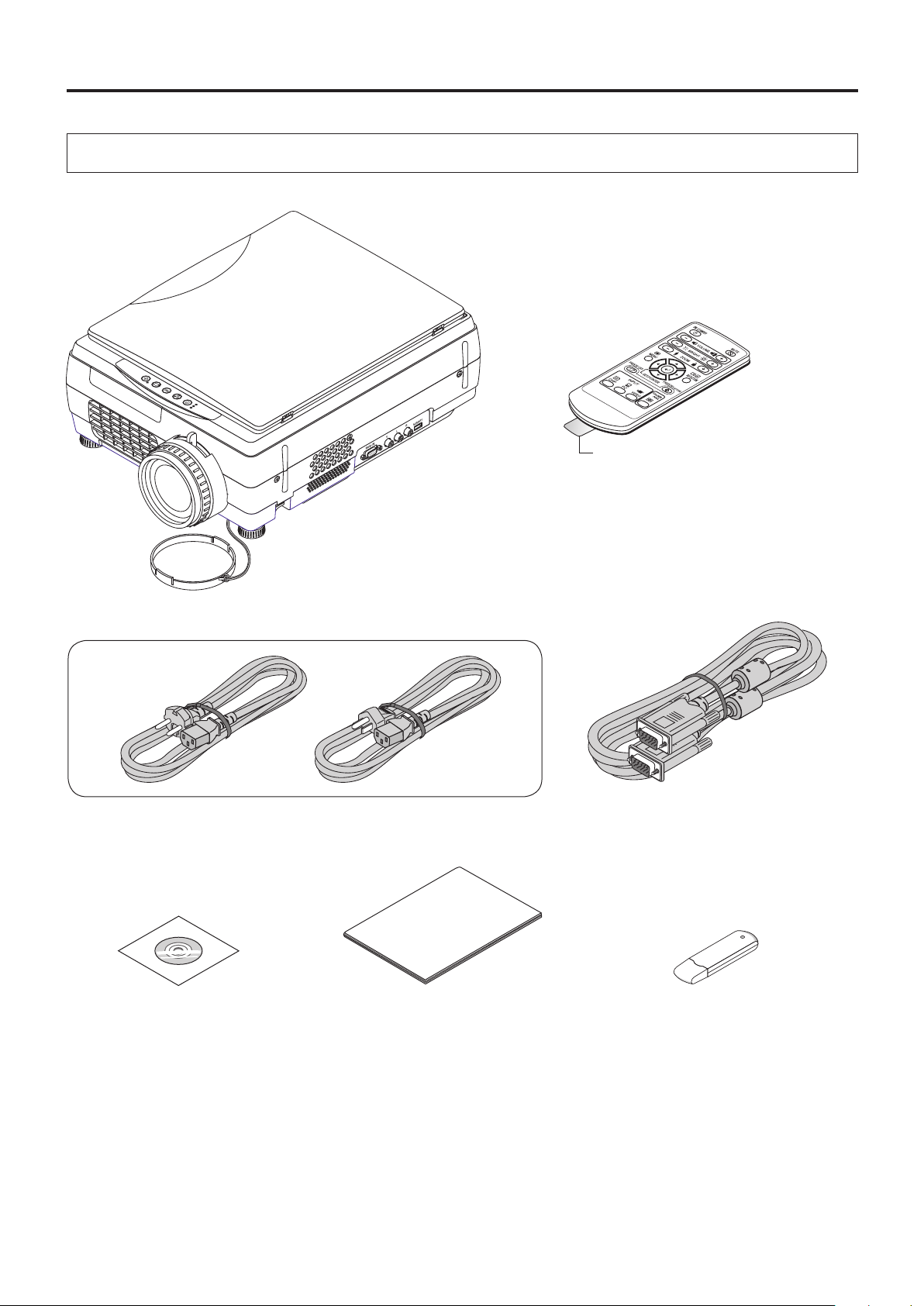
Supplied Parts Check
Please check that the supplied parts are included.
FREEZE
FREEZE OFF
PORTRAIT
INPUT
TEMP
LAMP/COVER
ON/STANDBY
Pull out the sheet before use.
Remote control
iP-01U
Projector
Coin-typelithiumbattery:CR2025
(Insidetheremotecontrol)
Powercable(3m)
CD-ROM
iP-01User’sManual
Lens cap
Important Information
iP-01 Important Information
PCconnectioncable(2m)
USB Memory
* USB memory is the supplied items
only for iP-01UE model.
E-9
Page 10
A Check of the Supplied Items and the Names of the Parts
Names and Functions of the Parts (Projector)
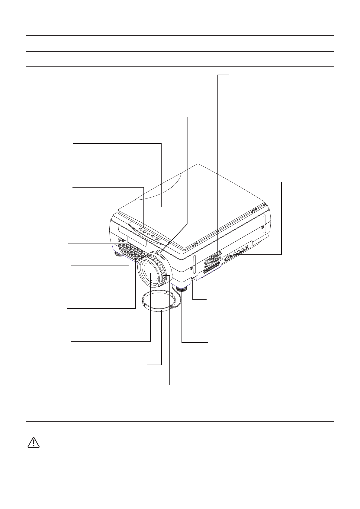
Zoomlever
Turn this to adjust the screen size.
See Page E-24.
Airintake
Air is drawn in from the side.
Documentcover
The document or printed material to be read is
placed under this cover.
See Page E-33.
Operationpanel
The b utt o n s used fo r regular
operation are located here. See
Page E-13.
Remotecontrol
IR sensor
Lampunitcover
(Underneathprojector)
The projection lamp unit is located inside.
See Page E-46.
Exhaustvents
Air is discharged from here.
Inputconnectorpanel
Include d are conn ectors for per-
sonal computer, video, and USB
memory*, etc.
* Only for iP-01UE.
FREEZE
FREEZE OFF
PORTRAIT
INPUT
TEMP
LAMP/COVER
ON/STANDBY
Tiltadjustmentlever
Press here to adjust the tilt foot. See Page E-24.
Projectionlens
The image is projected
from here.
* Be sure to remove the
lens cap before pro-
jecting.
• Duringunitoperation,donot obstruct thefrontofthelens.During operation, strong light through the
CAUTION
• Duringprojection,besuretoremovethelenscap.Negligencetoobserveitmaydeformthelenscap.
• When
Tiltfoot
This foot is used to adjust the vertical angle of the
projection as well as the left-right balance. Turn-
Lenscap
ing it to the left extends it and turning it to the right
shortens it. See Page E-24.
Focusadjustmentring
Turn this to adjust the focus.
See Page E-24.
lens is projected. Obstruct the front of the lens causes re or burn.
alampexplodes,itispossiblethatparticlesofglassandothermaterialmaybereleasedoutside
from the ventilation slots; therefore, do not bring your face close to the ventilation slots, or the air intake.
E-10
Page 11
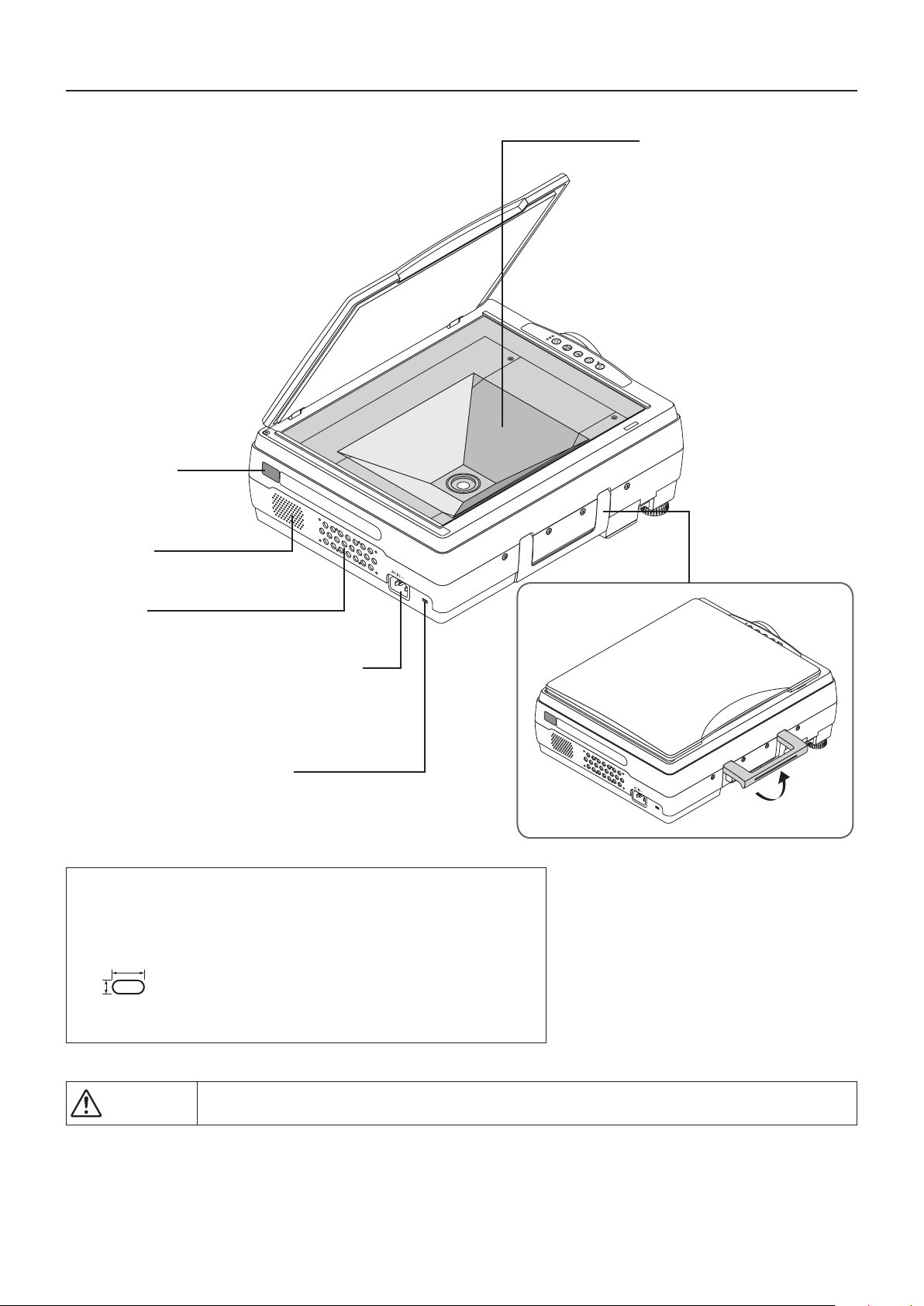
Remotecontrol
IR sensor
A Check of the Supplied Items and the Names of the Parts
Documentreadingarea
The document or printed mate-
rial that you wish to project in
the OHP mode is placed here.
See Page E-33.
ON/STANDBY
LAMP/
C
OVER
TEMP
INPUT
POR
TRAIT
FREEZE OFF
FREEZE
Speaker
(monaural)
Airintake
Air is drawn in from here.
Powerinputconnector
Plug in the power cable here. See
Page E-23.
Theftpreventionlock
Please see the Note below.
NOTE
Abouttheanti-theftlock
The anti-theft lock is compatible with Kensington security cable lock.
Contact the following for more information about the products.
7mm
3mm
Kensington Computer Products Group
Phone:(650)572-2700
Fax:(650)267-2800
URL:http://www.kensington.com
Handle
CAUTION
• Whenalampexplodes,itispossiblethatparticlesofglassandothermaterialmaybereleasedoutside
from the ventilation slots; therefore, do not bring your face close to the ventilation slots, or the air intake.
E-11
Page 12
E-12
A Check of the Supplied Items and the Names of the Parts
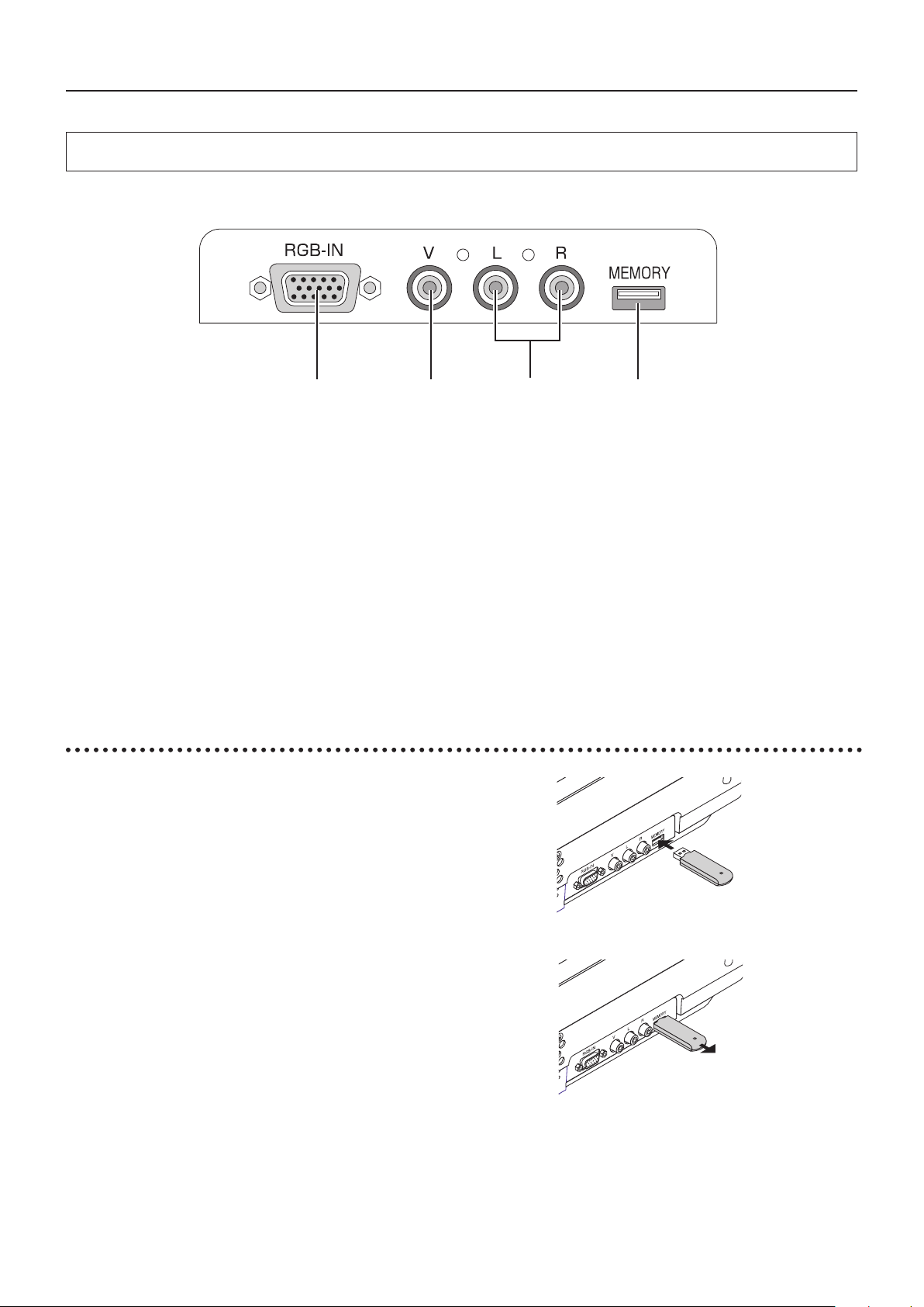
Names and Functions of the Parts (Input Connectors)
1.
Computer/video(Dterminaloutput)videoinputconnector
Usethisinputterminalforconnectiontoacomputer’sana-
log RGB input connector or a video deck’s D connector
outputusinganRGBconversioncable(soldseparately).
See pages E-18 and 22.
2. Videoinputconnector
Thisinputconnectorisforusewiththevideo(NTSC/PAL
/SECAM).SeePageE-22.
3. PC/VIDEOaudioinputjack
This is the audio input jack for PC/Video.(Stereo is sup-
ported)
TooutputtheaudioofaPC,usea(commerciallyavailable)
stereo mini plug to RCA stereo conversion cable.
See Pages E-16 and 22
NOTE:
Left and right channel sounds will be output from a monau-
ral speaker.
Sound will be output when audio is input regardless of the
PC/VIDEO mode setting. (Sound will not be output in the
OHPmode.)
4. USBconnector
This connector is for the insertion of a USB memory stick.
* Only for iP-01UE.
1 2
3 4
USB memory stick insertion and removal
InsertingaUSBmemorystick
Insert straight and all the way into the USB connector.
* Insert a USB memory stick only; nothing else.
RemovingaUSBmemorystick
* Pull out the USB memory stick after changing the input to a setting
other than OHP.
NOTE
Our optional USB memory stick is guaranteed to operate.
The other USB memory sticks are not guaranteed to operate.
Page 13
E-13
A Check of the Supplied Items and the Names of the Parts
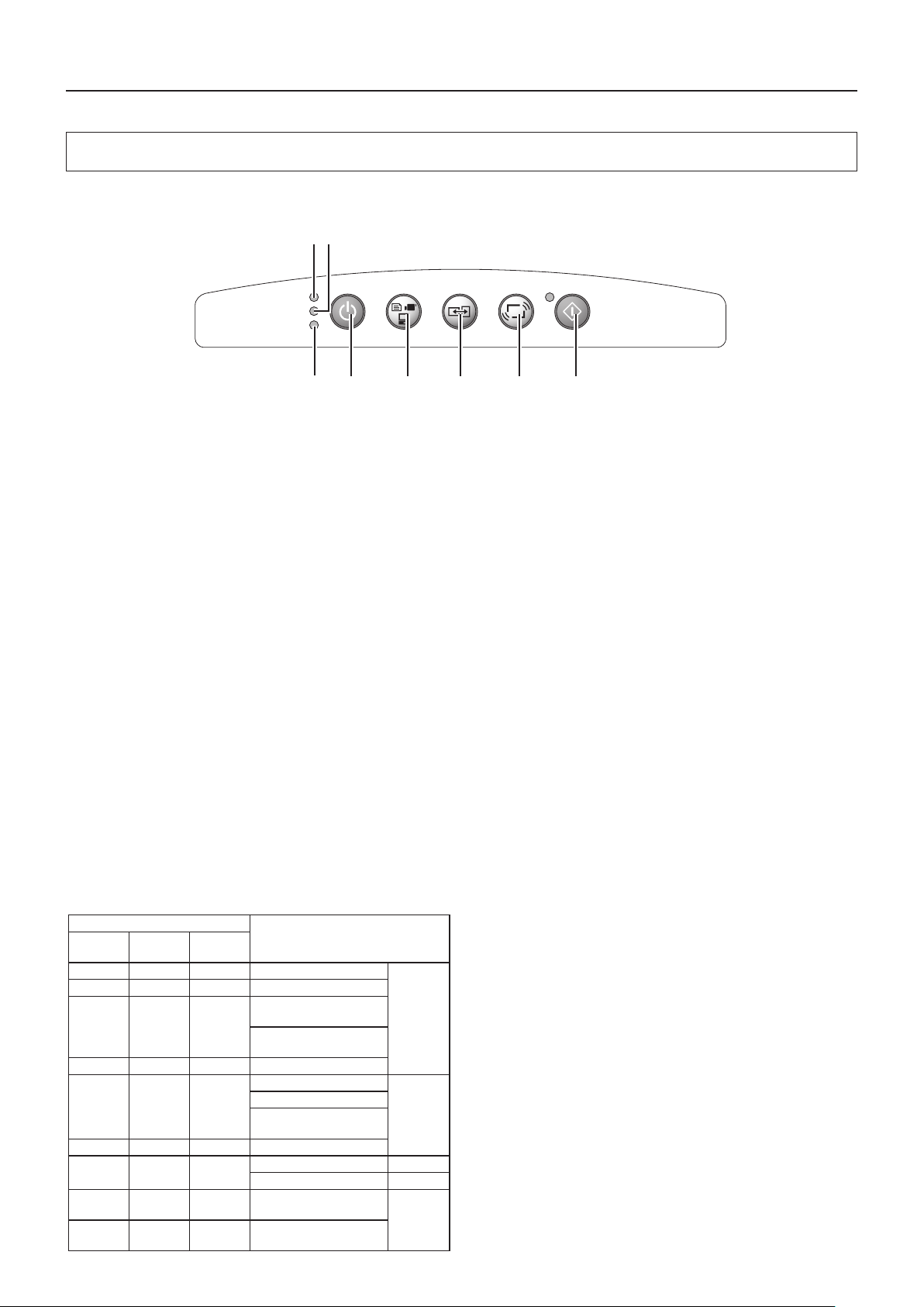
Names and Functions of the Parts (Operation Panel)
1.ON/STANDBYLED
Lit red during standby and lit green when the projection
lamp is on. See Page E-23.
2.LAMP/COVERLED
Lit green during projection. Lit red when the air filter or
lamp unit cover is not in place.
• Atthetimeoftheprojectionlamplightingoperation,the
LEDashesforabout6secondsandthenlightsgreen.
• Atthetimeofaprojectionlamplightingfailure,theLED
ashesgreen.(Theashingintervalwhentheprojection
lampis offwill be longerthanwhenthe LED ashesat
othertimes.)
• Whentheprojectionlampisoff,theLED ashesgreen
for 60 seconds and then goes off.
• Whenthe projection lamp has been used in excessof
1,900 hours, the LED ashes red; when use exceeds
2,000 hours the LED is lit a steady red.
See Page E-44.
3.TEMPLED
When the internal temperature has risen excessively, the
LED ashes red for 10seconds, then is lit a steady red.
See Page E-44.
LED List
LED State
Significance
ON/
STANDBY
LAMP/
COVER
TEMP
Off Off Off AC power OFF
Normal
condition
Red Off Off Standby
Green
Flashing
green
Off
Standby to start of projection
End of projection to
standby
Green Green Off Projecting
Red Red Off
Lamp cover open
Power
has been
switched
OFF
because of
the alarm
Lamp burned out
Lamp usage exceeds
2,000 hours
Red Orange Off Internal problem
Red Off Red
Temperature fault
Fan fault
Green
Flashing
red
Off
Lamp usage exceeds
1,900 hours
Alarm
sounding
Green Green
Flashing
red
Abnormal temperature
warning
4. ON/STANDBYButton
Switches the power of the projector on or off (standby
mode).
• Onlythisbuttoniseffectivewhentheprojectionlampisoff.
See Page E-23.
5. INPUTButton
Press this to switch the input.
The input switches as follows: OHP → PC → VIDEO or
OHP →VIDEO(D4)→ VIDEO.
See page E-25.
6. PORTRAITButton
When OHP is selected:Changes the orientation of the
projectionimageto0°and to90°.Screensthathavebeen
switched over are displayed to match the width.
7.FREEZEOFFButton
Cancels the still image mode.
Cancels the still image mode.
This is used when checking the projection screen while
moving the document.
See Page E-29.
8. FREEZE/CAPTUREButton
Makes the projection screen image into a still image.
When OHP is selected: Information will be saved to the
USB memory when the USB memory stick is inserted.
* When the USB memory stick is not inserted, the image
cannot be stored because only still images are displayed.
* Only for iP-01UE.
See Page E-28.
ON/STANDBY
LAMP/COVER
TEMP
FREEZE OFF
FREEZE
/CAPTURE
PORTRAIT
INPUT
1 2
3 4 5 6 7 8
Page 14
E-14
A Check of the Supplied Items and the Names of the Parts
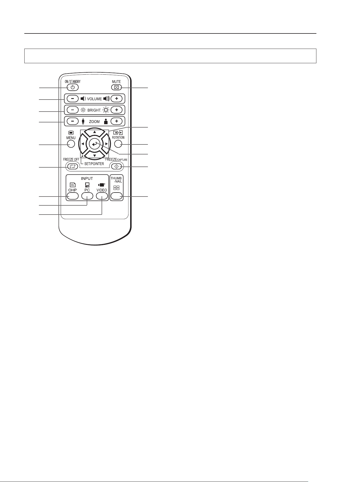
Names and Functions of the Parts (Remote Control)
1. ON/STANDBYButton
Switches the power of the projector on or off (standby
mode).
• Onlythisbuttoniseffectivewhentheprojectionlampisoff.
See Page E-23.
2. MUTEButton
Temporarily blanks the projection screen without switching
off the lamp. One more press causes the screen to return
immediately.
See Page E-32.
3. VOLUMEButtons
These buttons adjust the volume when the PC or video is
selected.
In addition, during the display of one history image, VOL-
UME + button advances the page, and the VOLUME – button moves back one page.
See Page E-31.
4. BRIGHTNESSButtons
These buttons adjust the brightness o f th e proj ect ion
screen.
See Page E-27.
5. ZOOMButtons
These buttons adjust the magnification of the projection
screen.
See Page E-26.
6. MENUButton
Switches on or off the display of the menu screen.
See Page E-35.
7. SCROLLButtons
Sets the selection of the item or the adjustment value at the
menu screen. Moves the zoom position during a zoom display. Moves the pointer when the pointer is being displayed.
See Pages E-26, 27, 29 and 32.
8. SET/POINTERButton
During menu display, this button advances the menu to
the next level. This button nalizes the setting at the time
of item selection. See Page E-34. This button displays a
pointer when the menu screen is not displayed. Press this
button one more time to make the pointer disappear.
9.ROTATIONButton
When OHP is selected, the orientation of the projection
screenswitches to 0° and to90°.Screensthathavebeen
switched over are displayed to match the width.
See page E-25.
10.FREEZE/CAPTUREButton
Makes the projection screen image into a still image.
WhenOHPisselected:DatawillbesavedtoUSBmemory
when a USB memory stick is inserted.
* When the USB memory stick is not inserted, the image
cannot be stored because only still images are displayed.
* Only for iP-01UE.
See Page E-28.
11.FREEZEOFFButton
Cancels the still image mode.
This is used when checking the projection screen while
moving the document.
See Page E-29.
12.OHPButton
Switches the projector to OHP input. See Page E-25.
13.PCButton
Switches the projector to PC input. See Page E-25.
14.VIDEOButton
Switches the projector to video input. See Page E-25.
15.THUMBNAILButton
Still images that have been captured on a USB memory
stick are displayed as thumbnails.
See Page E-29.
* Only for iP-01UE.
1
3
4
6
11
12
13
14
5
2
9
10
15
7
8
Page 15
A Check of the Supplied Items and the Names of the Parts
Operation of the Remote Control
• Pleaseusetheremotecontrolwithinarangeofabout7mfromtheremotecontrolIRsensoroftheprojector(locatedatboth
thefrontand rear)andwithinanangleof10degreesto the leftand10degreestotheright.Note thatthisdistancemaybe
shorter depending on battery consumption.
• Theremotecontrolwillnot functionwhenthereisan obstaclelocatedbetweentheremotecontrolandtheremotecontrolIR
sensor of the projector.
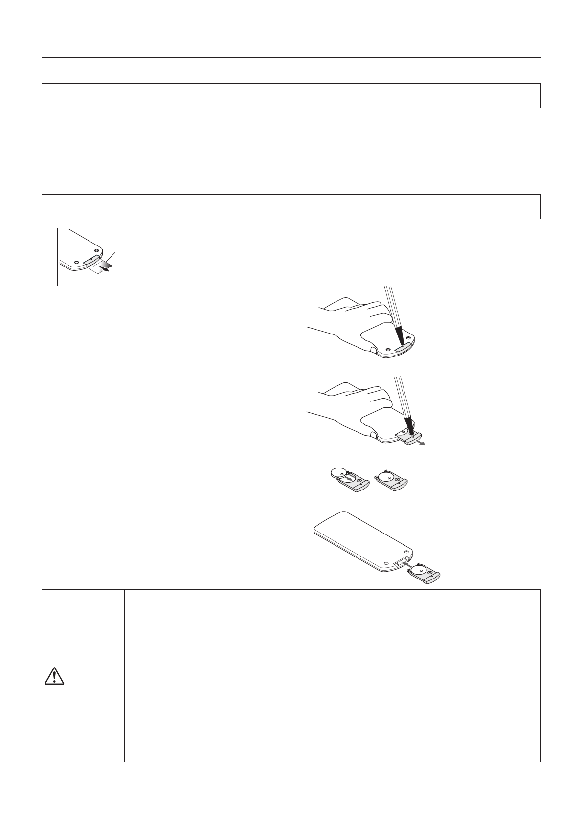
Battery Replacement
BeforeUsingtheProjector
Insulation sheet
1
Firmly hold the remote control with your hand and
insertthetipofaballpointpenorsomeotherpointed
objectintotheholeontherearside.
Notethatthereistheriskofscratchingthecasewhen
usingapointeditemsuchasanawl.
An insulation sheet has been inserted for protection during transportation prior
to shipping. Please pull out and remove the sheet before use.
2
Slidethe batteryholder towardyouby pressing from
abovewiththepointeditem,thenremovetheholder.
3
Insert the battery with the + side facing up as illus-
tratedontheinsideofthecase.
4
Returnthebatteryholdertoitsoriginalstate.
HandlingoftheRemoteControl
• Donotsubjecttheremotecontrol toastrongshocksuchasdroppingitfroma table. Doing so could
damage it and render it inoperable.
• Donotexposeittowaterorotherliquid.Iftheremotecontrolbecomeswet,wipeitdryimmediately.
• Avoidexposuretoheatand steam.Removethe coin-typelithium batterywhentheremotecontrolwill
not be used for an extended period.
CAUTION
• Donotdisassembleorheatthecoin-typelithiumbattery,northrowitintoare.
• Pleasefollowthedisposalmethodofyourregionindisposingoftheusedcoin-typelithiumbattery.
• Theremotecontrolmayfailtooperateor performance mayworsen when itis used nearan inverter
typeuorescentlamp.
• Please
• Pleasehandletheremotecontrolwithcare,sincetherearesomeoperationsavailableonlywithit.
storethecoin-typelithiumbatteryinaplacethatisoutofthereachofchildren.Ifthebatteryis
swallowed, promptly seek the care of a doctor.
NOTE:When it is time to replace the battery, please purchase a CR2025 coin-type lithium battery. The use of batteries having a
different shape such as the CR2032 may make removal difficult.
E-15
Page 16
Procedure Up to Projection
1
Considerationofplacementlocationandscreensize
Determine the screen and projector setup location.
Set the projector on a strong and stable, level platform.
See Page E-17 for information about the projection distance and screen size.
2
Connectionswithinputequipment
Connect your personal computer/video equipment.
Connections with the Personal Computer → See Page E-18
Connections with the Video Equipment → See Page E-22
3
Connectthepowercableandswitchonthepower
Switch On the Power → See Page E-23
Switch Off the Power → See Page E-23
4
Switchonthepowerofthepersonalcomputerorvideoequipment
5
Properlyadjust theprojection image
tothescreen
See Page E-17
→
0 - 6°
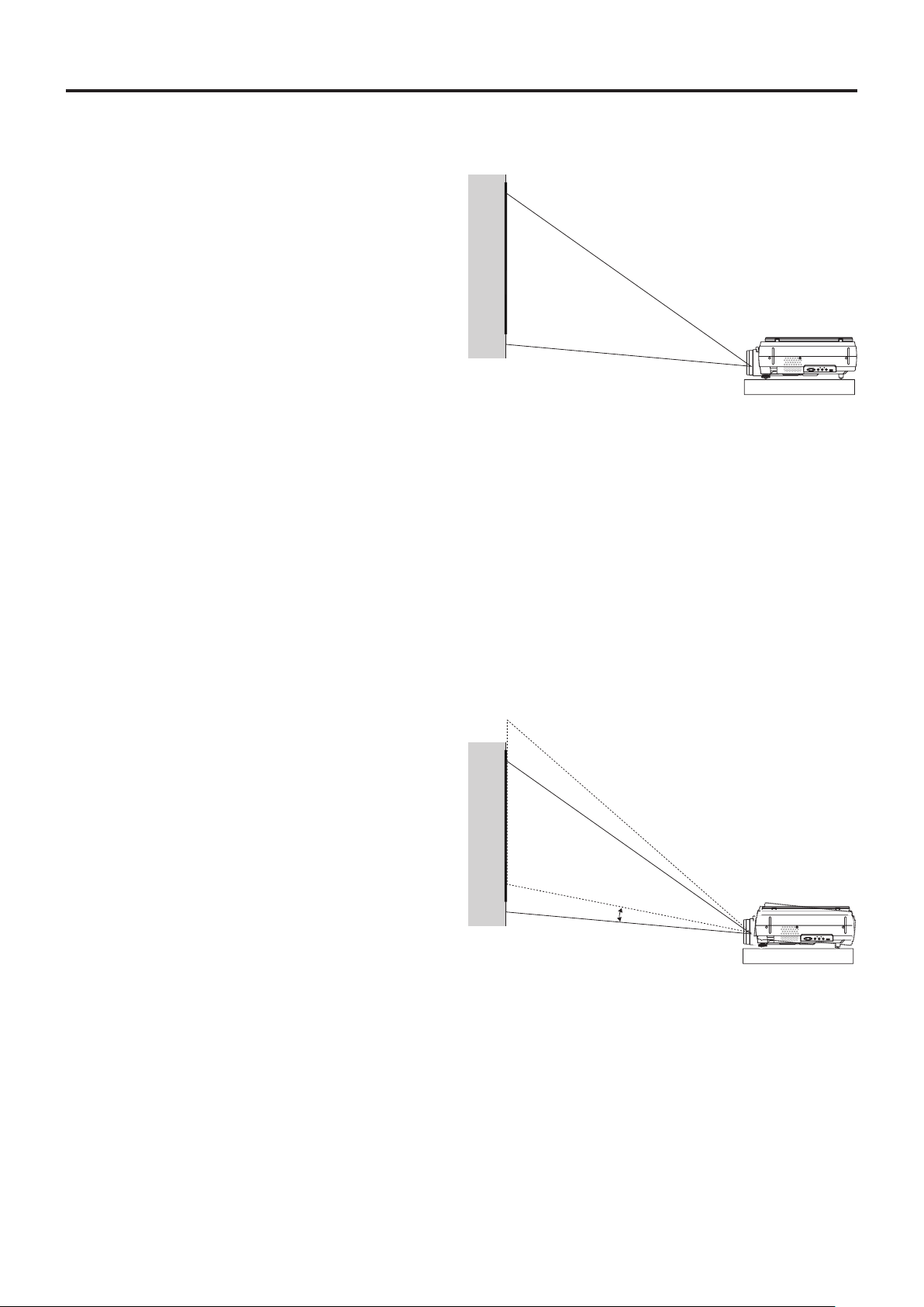
Performthetiltadjustmentoftheprojectortoprovidethedesiredprojectionheight.
The tilt adjustment allows the position of the projection image to be raised and lowered. The adjustment angle is from 0 de-
grees to 6 degrees.
Tilt adjustment → See Page E-24
6
Selecttheinputequipment
See Page E-25
→
7
Adjusttheimageorvideo
Adjust the image to provide the optimum condition, as required.
See Page E-42 - E-43
→
E-16
Page 17
E-17
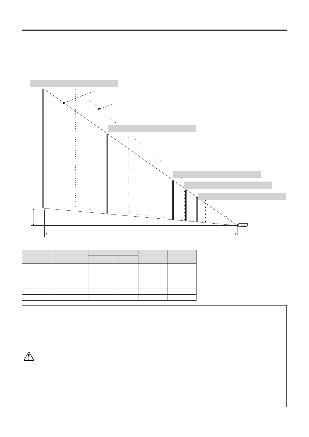
Please use the following diagrams to determine the screen display size and the type of screen required for any
given projector location.
Projection distances that will be in focuswill be 0.67 m (2.2 feet)to 6.1 m (20.0 feet) fromthe frontof the lens.
Please arrange the setup within this range.
Projection Distance and Screen Size
Wide: The size of the projection image
becomes maximum with the projection image size adjustment using the zoom lens
Tele: The size of the projection image
becomes minimum with the projection image size adjustment using the zoom lens
B
A
ScreenSize
When the zoom lever is at maximum on the telephoto side
When the zoom lever is at maximum on the wide side
200inches(approximately4.0x3.0m)
300inches(approximately6.0x4.5m)
100inches(approximately2.0x1.5m)
80inches(approximately1.6x1.2m)
60inches(approximately1.2x0.9m)
ProjectionDistanceTable
Screen size
(inches)opposite angle
Screen Size
A:Projectiondistance(m) B:Heightof
projection bot-
tomedge(mm)
Height(mm)
Wide Telephoto
300 6.0×4.5m 6.1 − 661 4572
200 4.0×3.0m 4.1 4.9 441 3048
100 2.0×1.5m 2.0 2.4 220 1524
80 1.6×1.2m 1.6 1.9 176 1219
60 1.2×0.9m 1.2 1.5 132 914
40 0.8 1.0 88 609.6
CAUTION
SetupLocation
• Donotplacetheprojectorinlocationsthatwillreachhightemperaturesorlowtemperatures.
Operationambienttemperature:0°C(32°F)to35°C(95°F)
• Setthescreensothatitisnotexposedtodirectsunlightorthelightofdirectillumination.Whenlighthitsthe
screen, the screen show a white cast and will be difficult to watch.
In a bright room, the curtains should be drawn or blinds closed and the area around the screen kept dark.
• Donotsetuptheprojectorinlocationsexposedtodampness,dust,greasysmokeortobaccosmoke.
Doing so will result in the adhesion of dirt to lenses, mirrors, and other optical parts and cause a degradation
of image quality.
• Donotplacetheprojectorinalocationwheretheventilationventswillbeblockedorinclosedareashaving
poorventilation.Doingsowillcausethetemperaturetoriseandcouldcauseareoraccident.(Theexhaust
ventsareatthefrontoftheprojectorandtheairintakeventsarelocatedattheside.)
• Donotplacetheprojectoratalocationwhereitmaybeproppeduporswayed.
• Duringunitoperation,donotobstructthefrontofthelens.Duringoperation,stronglightisprojectedthrough
the lens and if the front of the lens is obstructed by a matter or hand, it may cause re or burn.
• Duringprojection,besuretoremovethelenscap.Thelenscapmaybedeformed.
• Pleasedonot settheprojectorona tableor deskmatmade ofaheat-sensitivematerial.Tablemaybedis-
colored or desk mat may be deformed.
Page 18
E-18
CAUTION
ConnectionPrecautions
• To protectthisprojectorand the equipment tobeconnected,switchoffthepowerof each unit before
making connections.
• Please read the various equipment instruction manuals for information about the connection of the
equipment and the method of use.
• WhenconnectionismadewithanotebookcomputerandtheimageisdisplayedontheLCDscreenof
the notebook computer, a proper display might not be obtained on projection screen. Switching off the
display of the notebook computer will result in a proper display. The method of switching off the display
of the notebook computer will differ depending on the PC manufacturer. Please read the instruction
manual of the notebook computer for details.
• Connection might not be possibly depending on the model and settings of the personal computer.
Please contact your dealer of purchase for further information.
• TheimageofthePCcannotbeprojectedwhiletheUSBcableisconnected.ConnectthePCconnec-
tion cable.
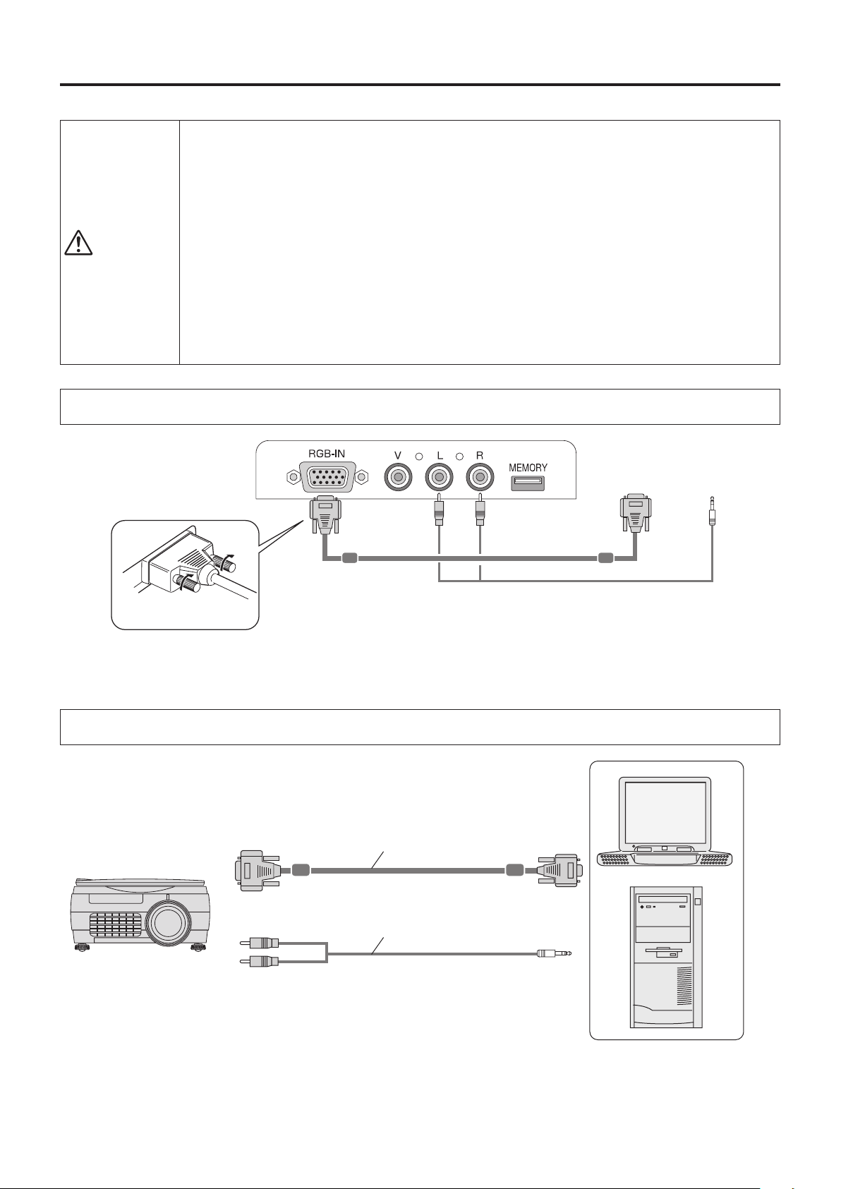
Connections with the Personal Computer
Basic Connections
Connections with Personal Computers
NOTE:
• AfterconnectingthePCconnectioncable,settheexternaloutputandthecomputer’sscreendisplaysettingsonthecomputer.
• Whenthesettingsoftheexternaloutputhavenotbeenmade,"Nosignalbeinginput"willbedisplayed.
• Whenaconditioninwhichasignalhasnotbeeninputcontinuesfor15minutesorlonger,thelampisturnedoffautomatically.
(Thisonlyfunctionswhentheautopoweroffmodeissetto“ON”.SeepageE-43.)
To the RGB outpu t c onn ec tor
of the pe rson al
computer
To the audio output
co nn ect or of the
personal computer
Plug in the connection cable
and fasten with the screws
NOTE:
• InputConnectors→ See Page E-10.
PCconnectioncable(Supplieditem)*
Stereo mini plug - to - RCA audio cable
(Commerciallyavailable)
Page 19

E-19
Personal Computer Input Connector
Personal Computer Input Connector
The personal computer input connector uses a 15-pin mini D-SUB type connector.
The pins and their corresponding signal inputs are described below.
54321
10 9876
15 14 13 12 11
Connections with the Personal Computer
⑥ GND
⑦ GND
⑧ GND
⑨ NC
⑩ GND
⑪ NC
⑫ SDA(DDC2B)
⑬ H.SYNC
⑭ V.SYNC
⑮ SCL(DDC2B)
① RED VIDEO
② GREEN VIDEO
③ BLUE VIDEO
④ GND
⑤ NC
Connecting Macintosh Computers
• WhenthemonitoroutputissettotheVGAport(miniD-SUB15-pin),mountthePCconnectioncableincludedwiththemainunit.
• AnoptionalApplevideoadaptercableisrequiredwhenthemonitoroutputisavideoportorDVIport.
NOTE:TheRGB(15-pin)inputconnectoroftheprojectorisoftheanalogtype.Thiscannot be connectedwithadigitaloutput
type of personal computer.
Page 20
E-20
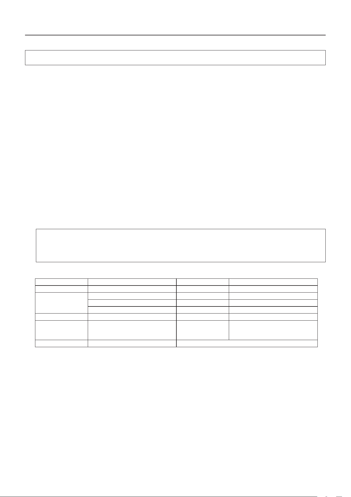
Connections with the Personal Computer
Please check the matters described below when the image of the personal computer is not projected or when there
is projection but the image is not correct.
●
The image is not projected
Whenthe externaloutput signalfromthepersonalcomputerisnotinput tothe iP-01,"Nocomputersignal being input" is dis-
played on the display screen of the iP-01. Should this occur, please check the following matters.
1
Tryrestartingthepersonalcomputer.
When the iP-01 is connected after the personal computer has been started, the connection of the iP-01 might not be recog-
nized by the personal computer. When the iP-01 has not been recognized, the external output signal from the personal com-
puter will not be output and there will not be an image to project.
2
Checkthefunctionsofthepersonalcomputer.
Depending on the notebook computer, some computers will require an operation to output a signal from the external output
connector. If this operation is not performed, the external output signal from the notebook computer will not be output.
Please see the instruction manual of the notebook computer you are using and perform the operation that will output the sig-
nal from the external output connector.
(OperationExample)
IBMPC/ATandDOS/Vcomputers:
Pressthe[Fn]key+"anyoneofthe[F1]to[F12]keys(notingthattheoperationwilldifferdependingonthemodel)"
PC98notebookcomputerslaterthantheNrSeries(withtheexceptionofthePC-98NX):
Pressthe"SuspendResume"switch.
Correspondence List for Connection Problems with the Personal
Manufacturer ExternalOutputSwitchingMethod Manufacturer ExternalOutputSwitchingMethod
IBM Fn+f7 DELL Fn+f8
NEC
Parallel output Toshiba Fn+f5
Switching from the Task Bar Panasonic Fn+f3
Fn+f3 Fujitsu Fn+f10
HP(FormerlyCOMPAQ)
Fn+f4 Mitsubishi Fn+f5
Sharp Fn+f5 Apple
Check mirroring with System environment setting → Display → Adjustment tab
SONY Fn+f7
When the Image of the Personal Computer Screen Is Not Projected
●
The screen of the personal computer is correct, but the image is not projected properly
Pleasecheckthefunctionsofthepersonalcomputer.
Even though the LCD screen of the notebook computer is properly displayed, the projected image might not be projected
properly. Due to restrictions of the notebook computer there will rarely be instances in which the setting of a simultaneous
display(i.e.,simultaneousoutputoftheexternaloutputsignalwhiledisplayingthescreenofthepersonalcomputer)willre-
sult in a signal that greatly deviates from the range supported by the iP-01 and proper projection will not be possible.
Should this occur, a proper image will not be obtained even when adjustments are made with the iP-01.
In some instances, the personal computer screen will be properly projected by the iP-01 when the simultaneous display is
cancelled and an operation is performed to output only the external output signal. Please see the instruction manual of the
notebook computer you are using for details.
* This table indicates the results of an independent investigation by us of representative computers made
by various manufacturers; it does not include all of the connections.
* Company names and product names mentioned are the trade marks or registered trademarks of the
respective companies.
Page 21
E-21
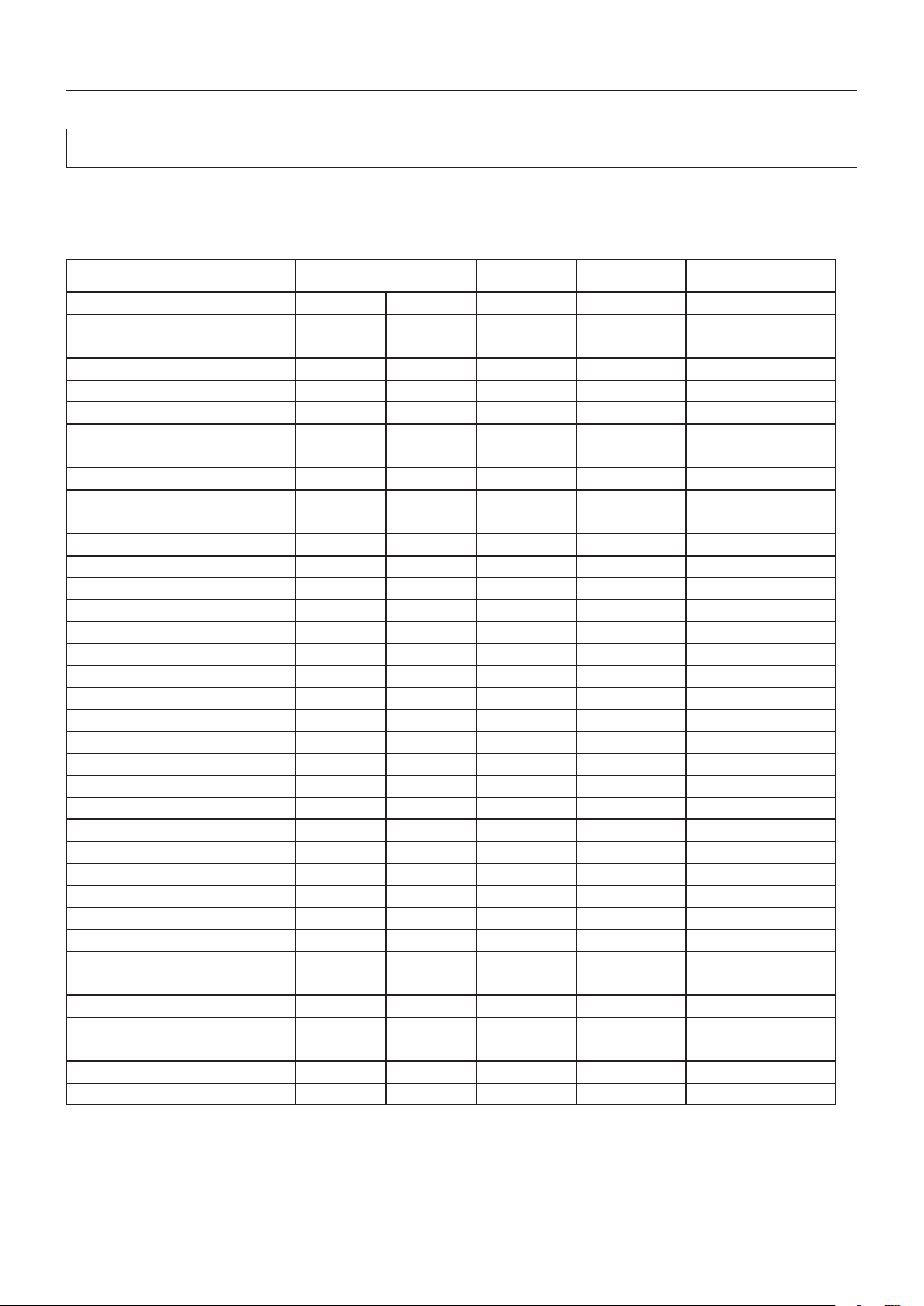
Signals indicated with a “Yes” are supported. Note that depending on the model of personal computer, please per-
formthescreenadjustmentofthe"Imageadjustment"→"Syncadjustment" menuif ickeringorbleedingappear
on the projection screen. → See Page E-40
Table of Supported Input Signals
Connections with the Personal Computer
Signal Name
Resolution
(Horizontal2Vertical)
Horizontal
Frequency(KHz)
Vertical Frequency
(Hz)
Supported
NTSC RGB - - 15.7 60 No
PAL/SECAM RGB - - 15.6 50 No
PC-98 Normal*
1
640 400 24.8 56 Yes
PC-98 Hi 640 400 31.5 70 Yes
VGA-GR1 640 480 31.5 60 Yes
VGA-GR2*
1
640 400 31.5 70 Yes
VGA-GR3*
1
640 350 31.5 70 Yes
VGA-TX1*
1
720 350 31.5 70 Yes
VGA-TX2*
1
720 400 31.5 70 Yes
640×480 72Hz 640 480 37.8 72 Yes
640×480 75Hz 640 480 37.5 75 Yes
640×480 85Hz 640 480 43.2 85 Yes
Mac13"RGB 640 480 35.0 66 Yes
800×600 56Hz 800 600 35.1 56 Yes
800×600 60Hz 800 600 37.8 60 Yes
800×600 72Hz 800 600 48.0 72 Yes
800×600 75Hz 800 600 46.8 75 Yes
Mac16"RGB 832 624 49.7 74 Yes
1024×768 43Hz 1024 768 35.5 43 No
1024×768 60Hz 1024 768 48.3 60 Yes
1024×768 70Hz 1024 768 56.4 70 Yes
1024×768 75Hz 1024 768 60.0 75 Yes
1024×768 85Hz 1024 768 68.7 85 Yes
MAC19"1024×768 1024 768 60.2 75 Yes
1280×768 60Hz 1280 768 47.7 60 Yes
MAC21"1152×864 1152 870 68.7 75 Yes
1280×800 60Hz 1280 800 49.7 60 Yes
1280×960 60Hz 1280 960 60.0 60 Yes
1280×960 85Hz 1280 960 85.9 85 No
1280×1024 60Hz 1280 1024 64.0 60 Yes
1280×1024 75Hz 1280 1024 80.0 75 Yes
1280×1024 85Hz 1280 1024 91.1 85 Yes
1600×1200 60Hz 1600 1200 75.0 60 Yes
1600×1200 65Hz 1600 1200 81.3 65 No
1600×1200 70Hz 1600 1200 87.5 70 No
1600×1200 75Hz 1600 1200 93.8 75 No
1600×1200 85Hz 1600 1200 106.3 85 No
• When the resolution of the input signal is lower than 1024x768 dots, the image is enlarged and displayed; if the resolution is
higher than 1024x768 dots, the image is reduced and displayed.
• Thesignalsabovemarkedwith(*)maynotdisplayproperlywhenfullkeystonecorrectionisapplied.Whenusingthesesignals
and applying keystone correction, please check the image while making the setting so that the image is not adversely affected.
• ThesignaltypesofD1toD4video(D1:525i(480i),D2-525p(480p),D3:1125i(1080i),D4:750p(720p)aresupported.
Page 22
E-22
Connections with Video Equipment
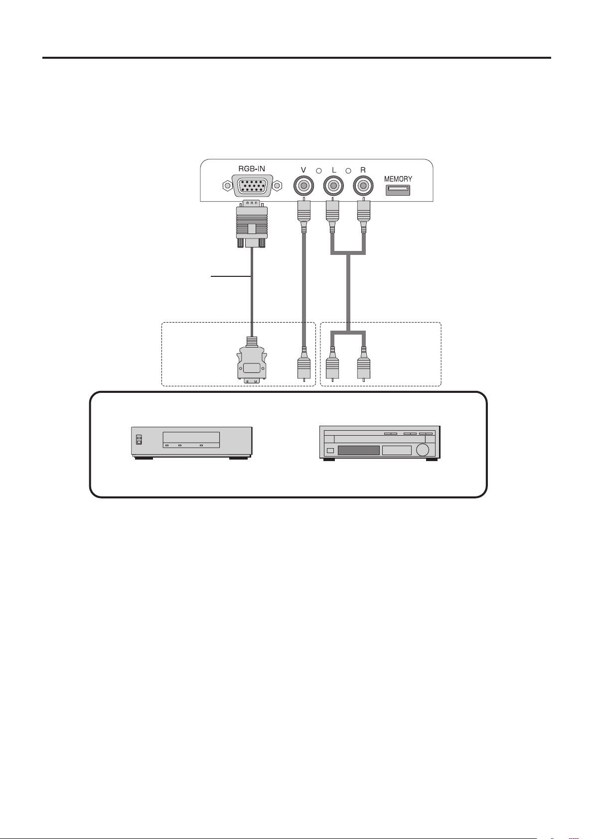
ThevideoofavideotapedeckorDVDplayerisprojectedontoalargescreen.
NOTE:
• Whenavideosignalhavealotofnoise,theimagemaybedisplayedinmonochrome.Shouldthisoccur,makea
settingwiththe"Videoselect"menutosuittheinputsignal.
• Whenaconditioninwhichasignalhasnotbeeninputcontinuesfor15minutesorlonger,thelampisturnedoff
automatically.
(Thisonlyfunctionswhentheautopoweroffmodeissetto“ON”.SeepageE-43.)
D terminal/ RGB conversion cable
(Option:ModelnameIPC-D/VGA)
iP-01 Projector side connector panel
To the video output
connector
To the audio
output con-
nectors
Videodeck
DVDplayer
Page 23
Connection of the Power Cable and On/Off Switching
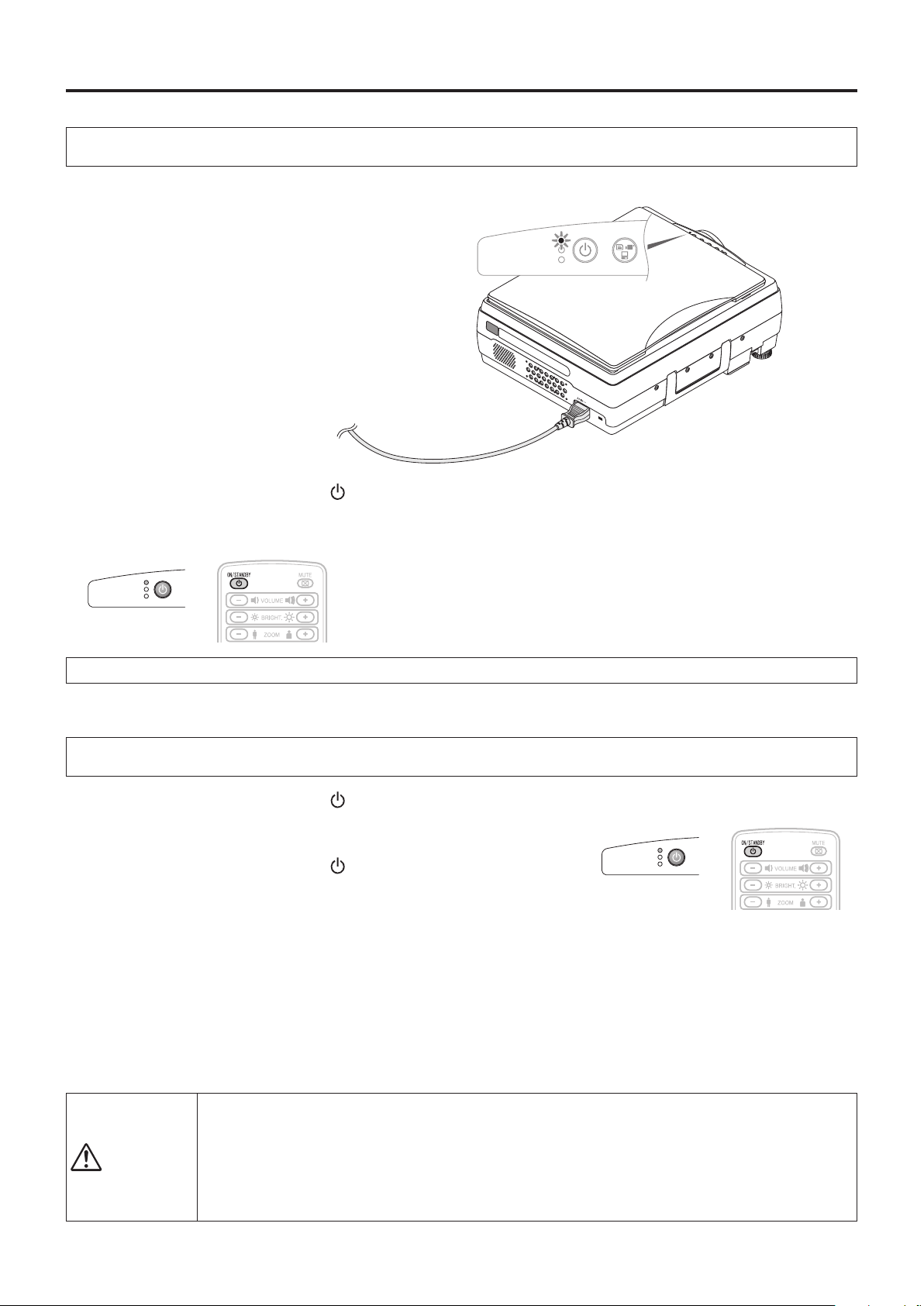
Switch On the Power
Connectthepowercable
1
The projector will enter the standby mode and the ON/
STANDBY LED will light in red.
To wall outlet.
PresstheON/STADNBYbutton( )
2
Operation with the
Projector
ON/STANDBY
LAMP/COVER
TEMP
Operation with the
Remote Control
The fan will turn, the lamp will light, and the ON/STANDBY LED will light in
green. The LAMP/COVER LED will light in green.
• IftheLEDlightsinredaftertheON/STADNBYbuttonispressed,projector
→ See Page E-50
• Check that the lens cap has been removed before pressing the ON/
trouble is indicated.
STADNBY button.
ON/STANDBY
LAMP/COVER
TEMP
INPUT
Theprojectorisnowabletomakeaprojection.
Switch Off the Power
PresstheON/STANDBYbutton( )
1
"PressON/STADNBYbuttonagaintoturnoff" will appear on the projection screen.
PresstheON/STANDBYbutton( )onemoretime.
2
Thelampwillgooff.
• TheLAMP/COVERLEDashesgreen,thenturnsoffoncecoolingiscompleted.
TheON/STANDBYLEDlightsinresistance.
• Whenthelampisoff,pressingtheON/STANDBYbuttonwhiletheLAMP/COVERLEDisashinggreenwillnotswitchthe
lamp on again.
To switch the lamp on again, please press the ON/STANDBY button again after the ON/STANDBY LED lights in red.
DisconnectingthePowerCable
3
The ON/STANDBY LED on the operation panel will go off.
Thepowercablecanalsobedisconnected(i.e.,directpowerofffunction)whenthelamp/coverLEDisashinggreen.
• Donotdisconnectthepowercablewhilethelampislit.
• AfterusingtheUSBmemorystick,besuretounplugitandstoreit;donotleaveitinserted.
CAUTION
• Disconnectthepowerplugoftheprojectorfromthepoweroutletwhentheprojectorwillnotbeusedfor
a long time.
• Whenyouwillbereinsertingthepowerplug into the poweroutletsoonafterdisconnectingit,allowa
xedinterval(ofapproximately10seconds)beforeinsertingit.
Operation with the
Projector
ON/STANDBY
LAMP/COVER
TEMP
Operation with the
Remote Control
E-23
Page 24
ON/STANDBY
LAMP/COVER
TEMP
FREEZE OFF
FREEZE
PORTRAIT
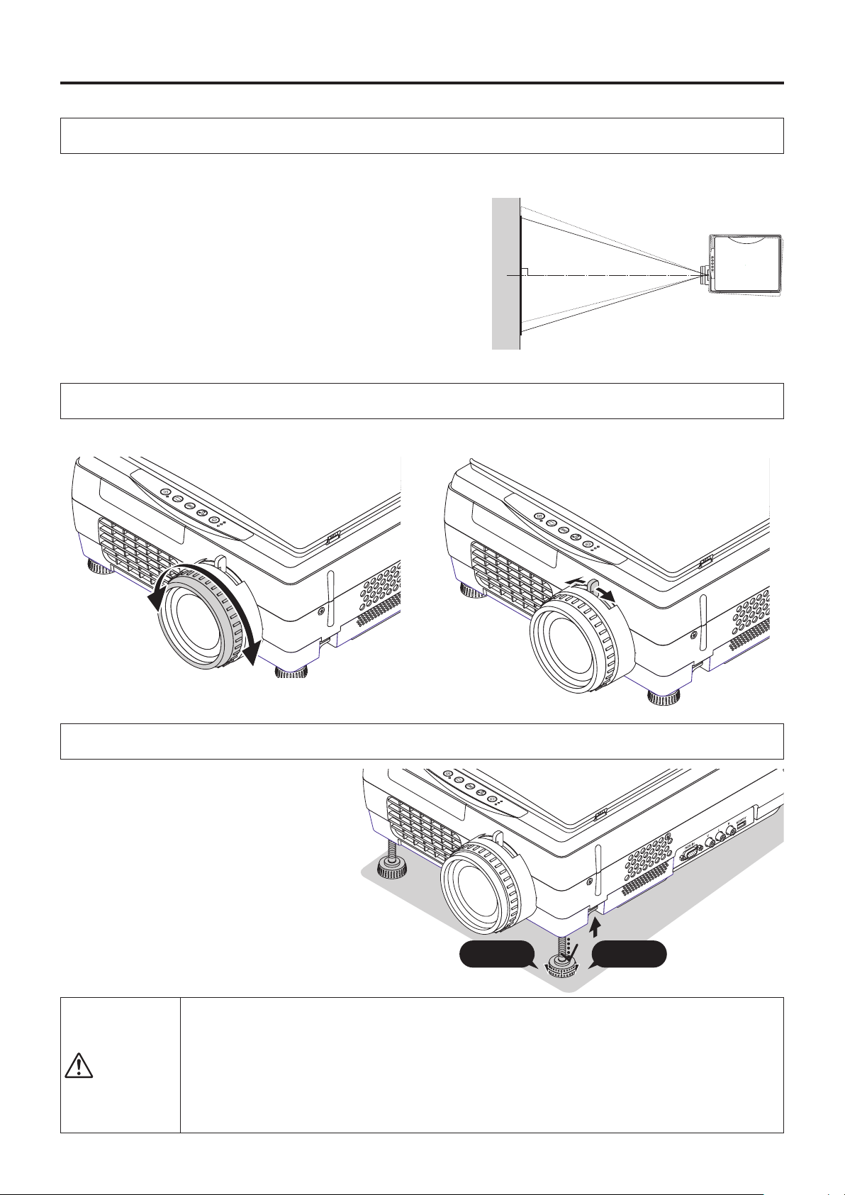
INPUT
Adjustment of the Projection Image
Adjusting the Projection Image
Adjust the projection image to the screen.
• Whentheimageisshiftedtotheleftorright,movetheprojectorhorizontally.
(Alignthecenterofthescreenwiththecenteroftheprojectorlens.)
• Whentheimage isshiftedupordown,usethetiltfoottoadjustthepro-
jector vertically.
• When
• When
Turn the focus ring/zoom lever of the projection lens and adjust the projection image.
theimageisslanted,turntheleftorrighttiltfoottoadjust.
there is distortion in the shape of a trapezoid, adjust with KEY-
STONE of the menu operations. See Pages E-36 and 42.
Making Focus/Zoom Adjustments
Right angle
FREEZE
FREEZE OFF
PORTRAIT
INPUT
TEMP
LAMP/COVER
ON/STANDBY
The image size depends on the projected distance. See page E-17.
Adjusting the Tilt (Slant)
FREEZE
Adjustment of the tilt foot allows the position
and slant of the projection image to be ad-
justed.
Press the left-right tilt adjustment lever and
raise the front of the projector. Release the
lever w h e n the desired he i g h t has been
reached. Rotating the lowest portion of the tilt
foot permits ne adjustments to be made. The
tilt foot are lengthened by rotated to the left
and shortened by rotated to the right.
FREEZE OFF
FREEZE
FREEZE OFF
PORTRAIT
INPUT
TEMP
LAMP/COVER
ON/STANDBY
PORTRAIT
INPUT
TEMP
LAMP/COVER
ON/STANDBY
Up Down
CAUTION
• Donotlengthenthetiltfootononlyonesidewhichwouldplacetheprojectoronanextremeslant.Doingso
could result in the projector slipping or falling over and could cause an accident or breakdown.
• Whenmovingtheprojector,besuretoreturnthetiltfoottotheoriginalposition.
ventilationholesontheprojector’ssidesandbottomtakeincoolingairusingastrongsuctionforce.If
• The
cloth or paper get stuck to them, the internal temperature will rise, leading to accidents or damage.
• Dependinguponthematerialoftheplacementlocation,therubberfeetmaysoilontheplacementsur-
face.
E-24
Page 25
Regular Operation
FREEZE OFF
FREEZE
/CAPTURE
FREEZE OFF
FREEZE
/CAPTURE
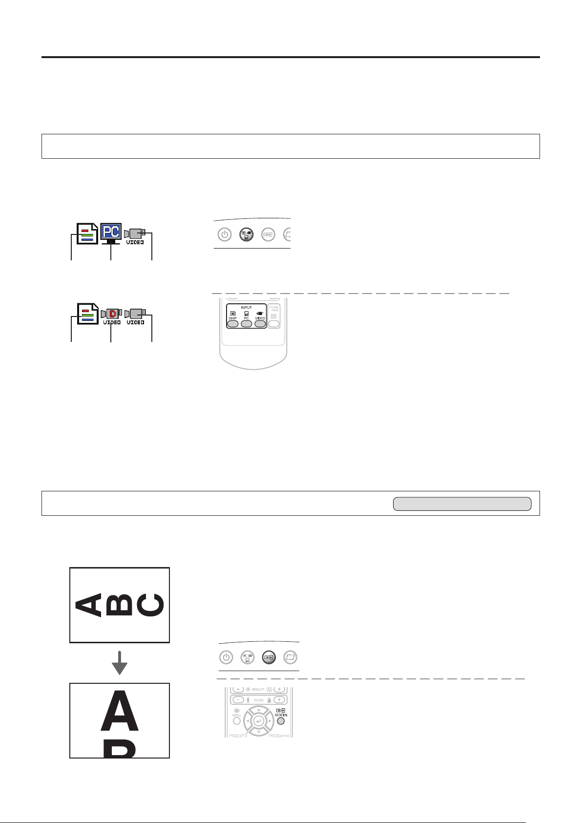
This section describes the use of direct operation using the projector and remote control buttons.
PleaseseetheitemsonPageE-36"MethodofMenuOperation"andPageE-38"MenuDescription"forinformation
about operation using the menu.
Select the Input
Whenthe projector’s power isturned on, one of the input selection icons([OHP, PC orVIDEO] or[OHP,VIDEO
(Component)orVIDEO])isdisplayed.
(WhenthePCinputissettoRGB)
OperationwiththeProjector
Select the input using the INPUT buttons.
The input switches in the order OHP → PC → VID-
EO or OHP →VIDEO(
Component
)→ VIDEO each
time the button is pressed.
OperationwiththeRemoteControl
Select the input using the INPUT buttons.
OHP PC VIDEO
(WhenthePCinputissettocomponent)
INPUT
PORTRAIT
OHP VIDEO
Component
(
VIDEO
)
* For instructions on selecting the PC input, see page E-38.
NOTE:
• Theinputmodeatstartingtimewillbethesameasitwasthelasttimethe
projector was switched off.
• Whentheiconisdisplayed,eithertheleftorrightkeypermitsinputswitch-
ing.
Changing the Orientation of the Projection Image
Thischangestheorientationofthecurrentlyprojectedimageto0°andto90°.
The changed video is displayed according to the lateral axis of the screen.
When 90-deg rotation is chosen
Effective Only with OHP Input
INPUT
PORTRAIT
OperationwiththeProjector
Press the PORTRAIT button.
OperationwiththeRemoteControl
Press the ROTATION button.
• Pressing the ROTATION button displays the rotation selection icon. With
changeover of the video, the display disappears.
E-25
Page 26
Regular Operation
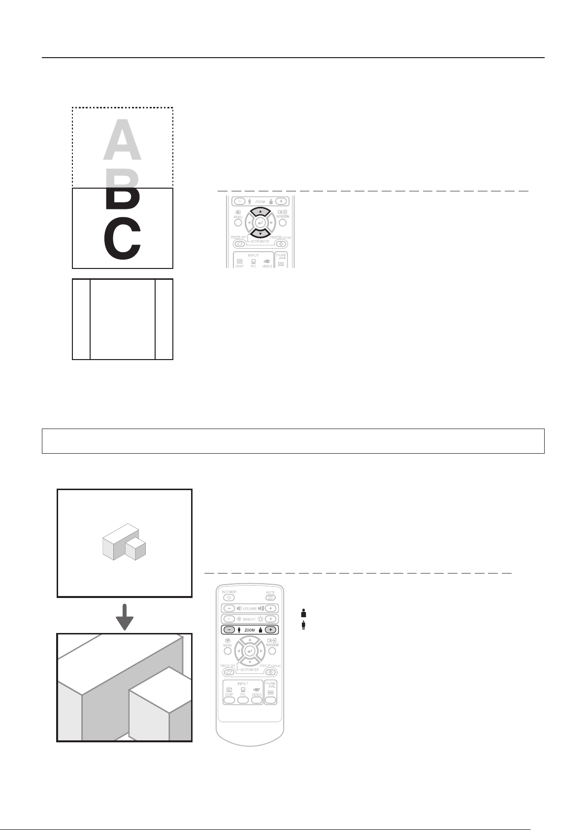
(+):投写画面を拡大します。
(−):拡大した投写画面を縮小します。
To view the portion that has been cut off
• PressingtheZOOM(–)buttonpermitsdisplayofalargeportionwithintheread-
A
ing range of the vertical display. The undisplayed portion can be displayed with
theSCROLL(▲▼)buttons.
B
OperationwiththeProjector
Scrolling is not possible from the main unit’scontrol
panel.
OperationwiththeRemoteControl
PresstheSCROLL(▲▼)buttonsandscrolltheprojec-
tion image up or down.
C
NOTE:When the orientation of the projection image is changed, even if the zoom function is in use, the display of the switched
screen will be adjusted to match the width, the same as with regular changes of orientation.
Enlarging and Reducing the Projection Image
This operation enlarges or reduces the size of projected image.
OperationwiththeProjector
Enlarging/reducingisnotpossiblefromthe mainunit’s
control panel.
OperationwiththeRemoteControl
Press one of the zoom buttons.
(+):Enlargethesizeoftheprojectedimage
(–):Reducethesizeoftheprojectedimage
E-26
Page 27
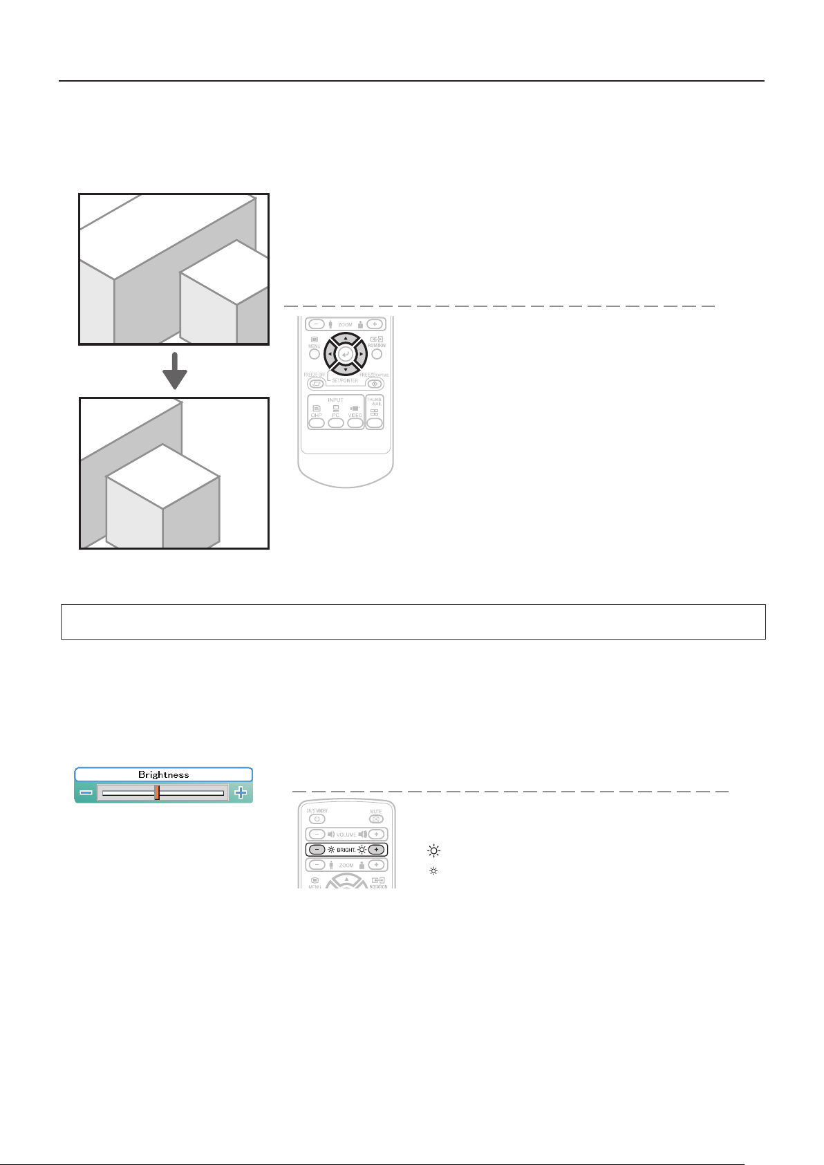
Moving the Screen
Movementispossiblein4directions(up,down,left,andright).
Regular Operation
OperationwiththeProjector
Scrolling is not possible from the main unit’s control
panel.
OperationwiththeRemoteControl
PresstheSCROLL(▲▼◀▶)buttons.
Adjusting the Brightness
To change the brightness, perform a manual adjustment using the method described below.
OperationwiththeProjector
Thebrightnesscannotbeadjustedfromthemainunit’s
control panel.
Brightnessadjustmentbar
NOTE:
• Ifno operationisperformedforseveralseconds whilethebrightnessadjustmentbarisdisplayed,thebrightnessadjustment
bar turns off.
OperationwiththeRemoteControl
AdjustusingtheBRIGHTNESS(+)/(-)buttons.
(+):Projectionimagebecomesbrighter
(–):Projectionimagebecomesdarker
E-27
Page 28
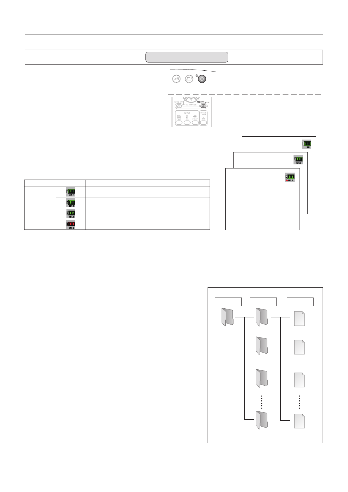
Regular Operation
Capturing the Projection Image
When inserting the USB memory stick
Valid only when OHP is selected and the USB
memory stick is inserted
FREEZE OFF
FREEZE
PORTRAIT
/CAPTURE
Pressing the FREEZE/CAPTURE buttonwill automatically
store the OHP document on the USB memory stick as an
OHP history image.
The projected image will become a still display.
* Pressing the still image/capture button while zoomed
into the OHP document will temporarily display the entire
OHP document on the le list screen; however, while pro-
jecting full screen, the zoom condition at the time the still
image/capture button is pressed will be stored.
* This function is available for the iP-01UE model only.
At image capture, the icon is displayed. The icon display differs depending on
the memory capacity currently used.
Icon Memory capacity
Capture of one history image to below 33% of the memory capacity used
USB memory
stick saving
33% to below 66% of the memory capacity used
More than 66% of the memory capacity used
/
Still Image Display
OperationwiththeProjector]
Press the still FREEZE/CAPTURE button.
OperationwiththeRemoteControl
Press the still FREEZE/CAPTURE button.
Saving disabled
Files saved on the USB memory stick
CapturedimageswillbesavedwithalenameofMMPJxxxx(withxxxxbeingfrom0001to1000)inthefolderXXXAVMPJ(with
XXXbeingbetween100and499)whichislocatedinthe“DCIM”folder.
Up to 1,000 images are stored in one folder, and when 1,000 images are exceeded a new folder will be created automatically.
Toautomaticallysaveale
When you would like to save images to a new folder before the number of
images reaches 1,000, create a folder on the PC with a name to which 1
has been added to the gure XXX of the folder named “XXX AVMPJ” that
currently exists in the USB memory.
The captured images that follow will be saved to the folder in the USB
memory having the largest XXX gure.
Example:Whenthecurrentfolderis“100AVMPJ”,creating“101AVMPJ” will
result in the images being saved automatically to the folder “101AVMPJ”,
whichreectsthelargestgure.
* When the size of a single stored image is 500 KB, approximately 4,000
imagescanbestoredon a2GBUSBmemory stick.(The size per imagewilldifferdependingontheimagesthathavebeenstored.)
* Our optional USB memory stick is guaranteed to operate.
The other USB memory sticks are not guaranteed to operate.
* For safety sake, please make a backup of the USB memory stick that
you are using.
* The initialization of the USB memory is performed from the menu
screen.(SeepageE-38)
* The aforementioned operation for the purpose of saving les automati-
cally cannot be performed with the projector. Please perform the operation on the PC.
suretoperformtheinitialization(formatting)oftheUSBmemoryus-
* Be
ing FAT 32.
* When there are a large number of recorded images, the speed of saving/
playback may become slower.
FileStructure
Folder Folder File
Folder Folder
DCIM 100AVMPJ
Folder
101AVMPJ
102AVMPJ
499AVMPJ
MMPJ0001.JPG
MMPJ0002.JPG
MMPJ0003.JPG
MMPJ1000.JPG
E-28
Page 29
E-29
WhentheUSBmemorystickisnotinserted
Each time the FREEZE/CAPTUREbuttonispressed,thecurrentlyprojectedimagewillbefrozen(inaxeddisplay).
NOTE:
• TheFREEZELEDislitgreenduringthestillimagedisplay.
• ApressoftheFREEZE/CAPTUREbuttonwhileamovingimage isprojectedwillresultinastillimagedisplayatthe existing
zoom magnication and position.
• ApressoftheFREEZE/CAPTUREbuttonatthetimeofstillimageofOHPwillresultinareturnofthezoommagnicationand
position to the original condition.
• IftheINPUT button on the main unit or the OHP, PC or VIDEO button on the remote control unit is pressed while displaying a still
picture,thecomputer’sorvideo’sstillpictureiscanceledandtheinputchanges.IntheOHPmode,thestillpicture remains.
Cancelling the Still Image Display
OperationwiththeProjector
PresstheFREEZEOFFbutton.
OperationwiththeRemoteControl
PresstheFREEZEOFFbutton.
OperationwiththeProjector
AnykeyotherthantheFREEZE/CAPTUREbuttonwill cancel
the operation.
OperationwiththeRemoteControl
AnykeyotherthantheFREEZE/CAPTUREbuttonwill cancel
the operation.
Regular Operation
FREEZE
/CAPTURE
PORTRAIT
FREEZE OFF
AttimeofOHPinput
AttimeofPC/Videoinput
Conducting a presentation using USB memory stick images
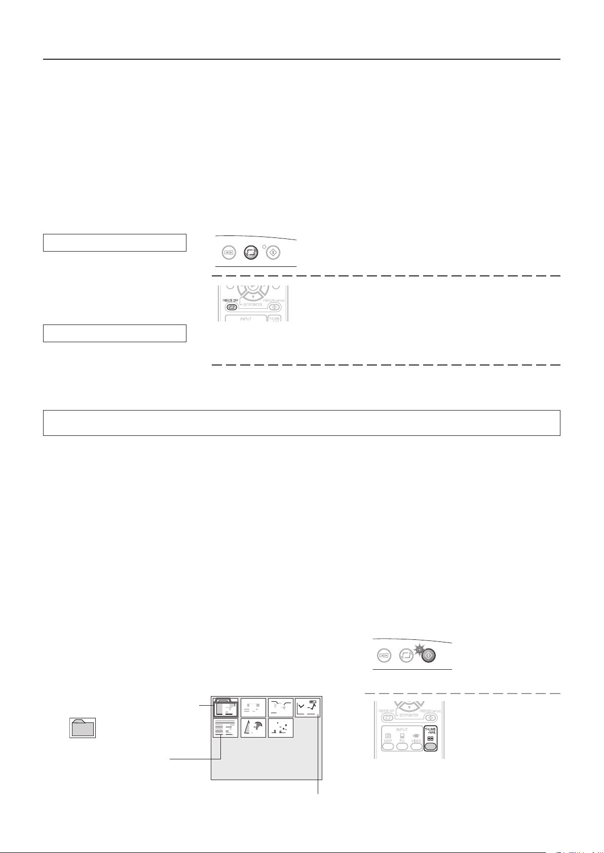
History images that have been saved on a USB memory stick are projected with a projector.
Conducting a presentation using USB memory stick images
*
* Our optional USB memory stick is guaranteed to operate.
Operation will not be guaranteed with other USB memory sticks.
The processing speed may become slower depending on the type of USB memory stick.
* This function is available for the iP-01UE model only.
* Do not put a le which is made in other devices to the folder. The act is a cause of the malfunction.
* Ifafolderimagebecomesgraywhenyoupressedtheremotecontrol’sTHUMBNAILbutton,pleasepressFREEZEOFFbut-
ton. And try again.
1
Preparethematerial
Insert a USB memory stick into the projector. Page E-12
• Usingthe iP-01tool,imagesotherthanthosecapturedwiththisprojectorcanbeconverted,andtheycan beprojected
with this projector.
2
Openthefolderlist
Presstheremotecontrol’sTHUMBNAILbutton.
The FREEZE/CAPTURELEDofthemainunitgoesoninorange (to
indicatethehistorymode).
• 16folderscanbedisplayedatonce.
Operationatthemain
unit
FREEZE/CAPTURE
LED(orange)
Operationwiththe
RemoteControl
Foldercursor(red)
Folderimage(thumbnail)
When there is no title le, the images
of the rst folder will be displayed on
a screen of reduced size.
The image les will be among these.
The image le is put in it.
Folder list display
Numbers are fo r explanatory pur po ses and actually,
numbers 1 to 16 are displayed.
F-2F-3F
-4
F-5F-6F
-7
F
-1
Inside the folder image
displayed, the image saved
with the unit is contained.
FREEZE OFF
PORTRAIT
FREEZE
/CAPTURE
Page 30
Regular Operation
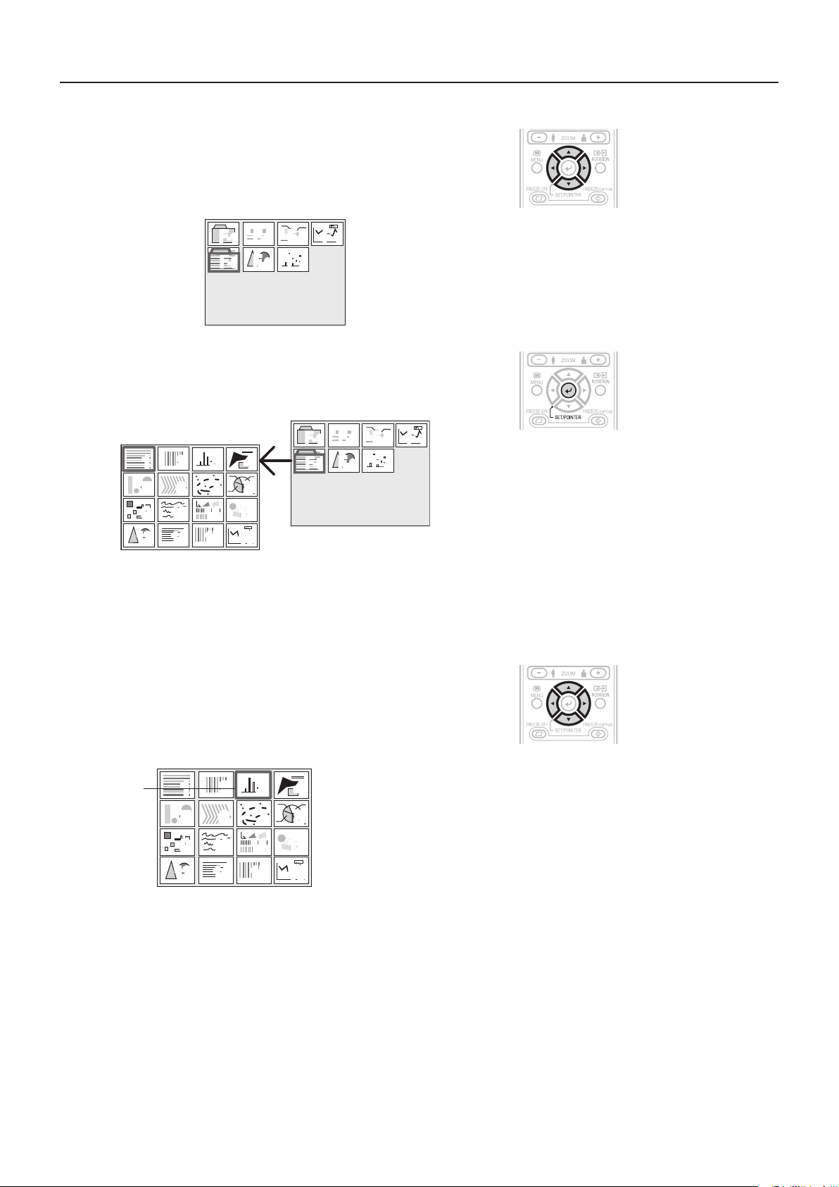
3
Choosingafolder
Press the remote control’s scroll ▲▼◀▶ buttons to set the
folder cursor to the folder image you want to project.
When the number of the folder images exceeds 16, pressing the scroll
button changes over to the other page.
F-2F-3F
F
-1
F-5F-6F
4
Openthelelist
Press the remotecontrol’sSET/POINTER button to open the
le list.
• Theimagedisplayedonthefolderlististherstoneinthelelist.
10
34
78
11 12
15 16
12
56
9
13 14
-4
-7
F-2F-3F
F
-1
F-5F-6F
-4
-7
Operationwiththe
RemoteControl
Operationwiththe
RemoteControl
NOTE:
The image that was changed over and saved in the vertical direction is projected vertically even when it is displayed laterally
in the reduced-size screen.
5
Choosingale
Press the remote control’s scroll ▲▼◀▶ button and set the
cursor to the reduced image you want to project.
When the number of the reduced size screen images exceeds 16,
press the scroll
Cursor
NOTE:
The image le that cannot be played back with the unit is not displayed.
button to display the 17th reduced screen image.
▼
12
56
9
10
13 14
34
78
11 12
15 16
Operationwiththe
RemoteControl
E-30
Page 31
Regular Operation
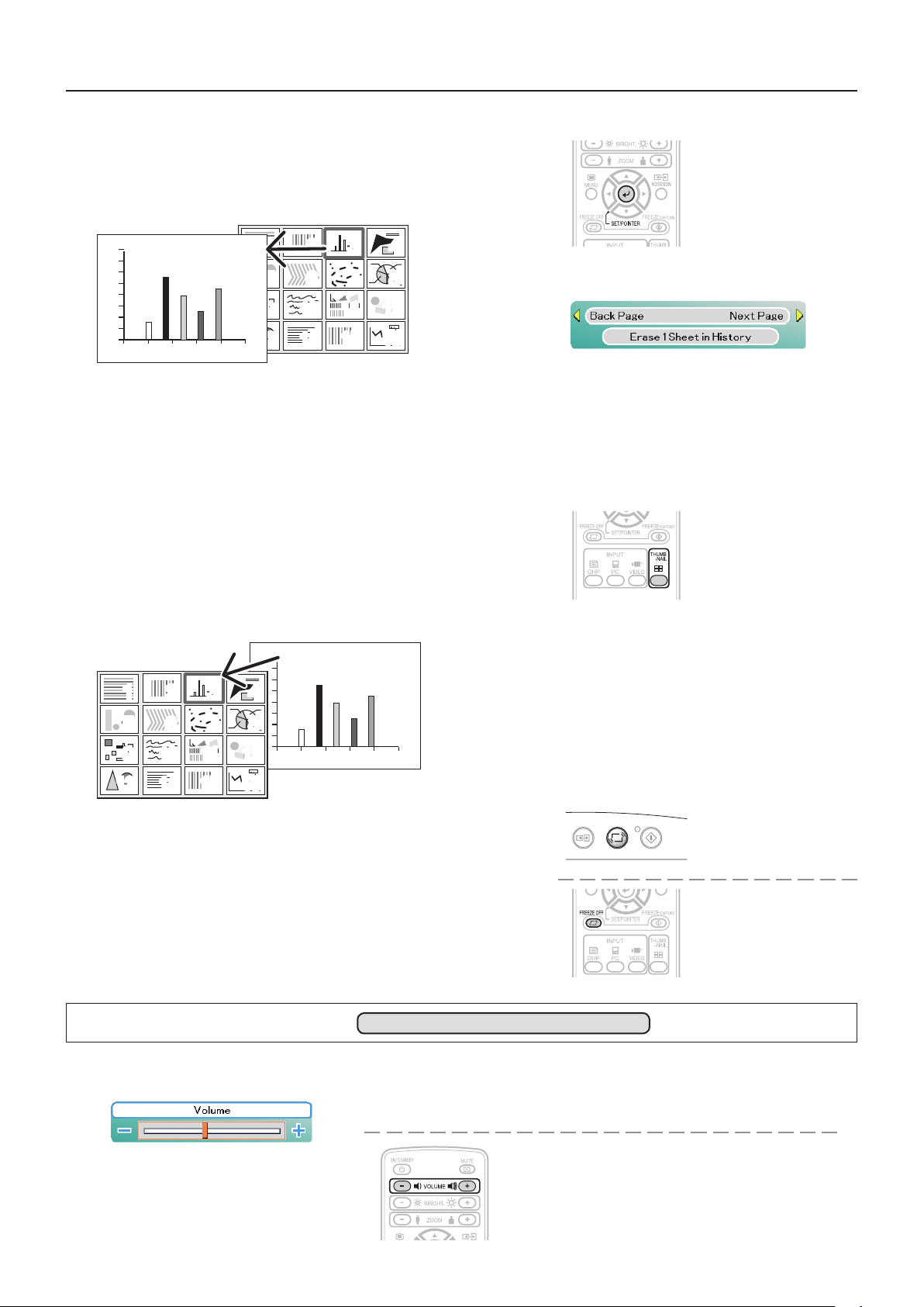
6
Projectiononthefullscreen
Press the SET/POINTER button of the remote control.
The reduced image at the cursor position is projected on the full
projection screen of the projector.
12
56
9
10
13 14
When feeding a page, choose the menu “Next.”
The operation can also be changed with the VOLUME + and VOLUME –
buttons of the remote control.
* When the zoom is at the minimum, pressing the SCROLL button
permits switching to the image before the displayed image, and press-
ing the SCROLL button permits switching to the next image.
7
Choosingtheotherimage
Press the remote control THUMBNAIL button and return to the le
list display. To choose another image in the folder, press the Scroll
▲▼◀▶ button.
To return to the folder list, press the THUMBNAIL button again.
Start operation with step 3 to choose an intended image.
34
78
11 12
15 16
Operationwiththe
RemoteControl
Onscreenoperation
Operationwiththe
RemoteControl
12
56
9
10
13 14
8
Projecting/terminatingtheOHPimage
PresstheremotecontrolFREEZEOFFbuttonorOHPbutton.
See Page E-12 for information about removal of the USB memory
stick.
NOTE:
When using the PC to perform operations on the image data on the USB
memory stick, handle the data copied from the USB memory stick to
prevent it from becoming unreadable on the projector after the operation.
Adjusting the Volume
34
78
11 12
15 16
Effective only During PC and VIDEO Input
FREEZE OFF
PORTRAIT
OperationwiththeProjector
Volume adjustment cannot be made at the operation
panel of the projector.
FREEZE
Operation
/CAPTURE
Projector
FREEZE/CAPTURE
LED(lightoff)
Operationwiththe
RemoteControl
withthe
Volumeadjustmentbar
If no operation is performed for several
NOTE:
seconds while the volume adjustment ba r is
displayed, the volume adjustment bar turns off.
E-31
Operation
AdjustusingtheVOLUME(+/-)buttons.
withtheRemoteControl
Page 32
Regular Operation
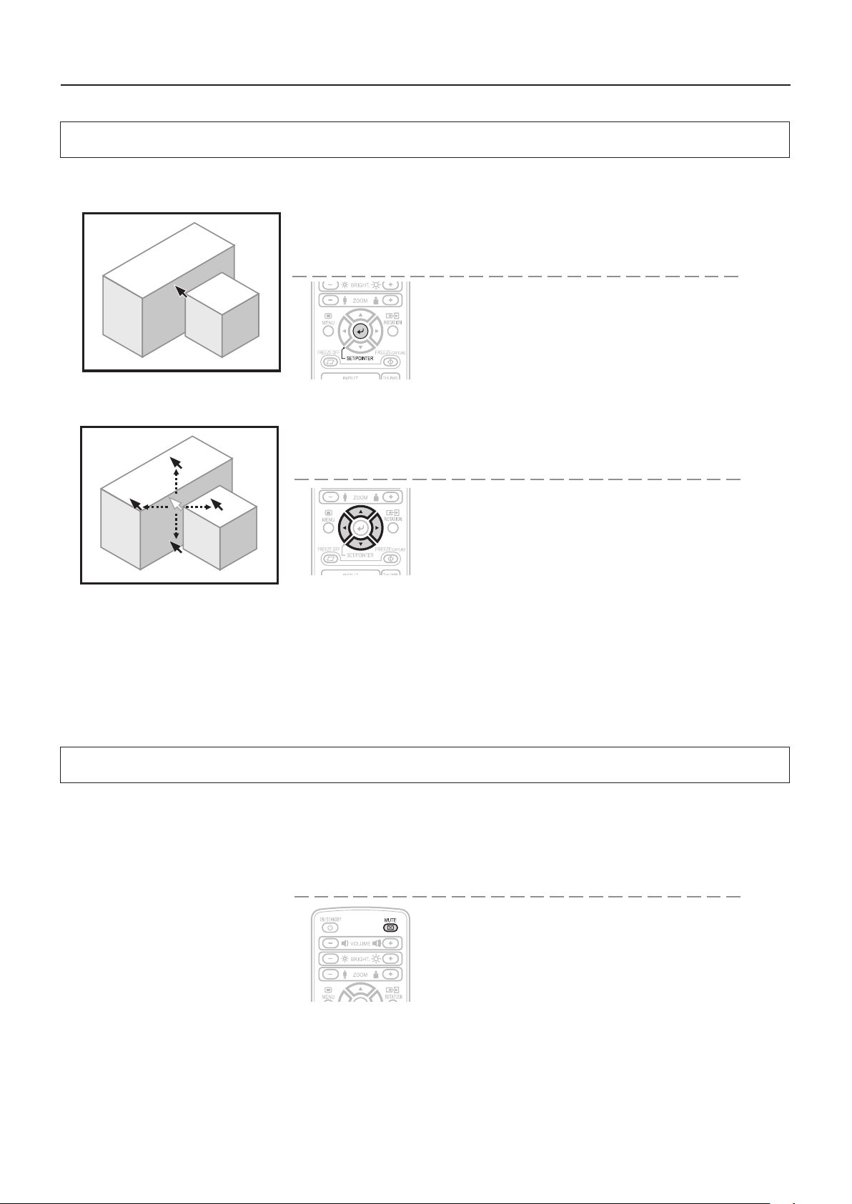
Displaying the Pointer
This operation displays the pointer in the currently projected image.
OperationwiththeProjector
The ability to turn on and turn off the pointer is not
available from the operation panel of the projector.
OperationwiththeRemoteControl
Press the SET/POINTER button.
One more press of the SET/POINTER button while the
pointer is displayed will turn off the pointer display.
Moving the Pointer
OperationwiththeProjector
Scrollingisnotpossiblefromthemainunit’scontrolpanel.
OperationwiththeRemoteControl
PresstheSCROLL(▲▼◀▶)buttons.
See Page E-38 for information about the form, color, and size of the pointer.
NOTE:
If the brightness is adjusted while the pointer is displayed, the pointer disappears temporarily, but it reappears once the
brightness adjustment bar turns off.
DuringKeystonecompensation(trapezoidalcompensation),whenthepointerisdisplayed,thepointercolormaybecomestriped.
It is not a failure.
Note that the pointer cannot be displayed during still image conditions of the PC/Video mode.
Deleting the Projection Image and Audio
This operation deletes the currently projected image and audio without switching off the lamp.
OperationwiththeProjector
The ability to delete the projection image is not available from
the operation panel of the projector.
OperationwiththeRemoteControl
Press the MUTE button.
NOTE: When a xedperiod of time elapses (about 30 minutes) with the video/audio muted,a message will be displayedto
checkwhethertoshutdowntheprojector.Selectionof"Yes"willsettheprojectortothestandbymode,whileaselectionof"No"
will again delete the video/audio.
When there has been an absence of an operation for 30 seconds during the display of the above conrmation message, the pro-
jector automatically enters the standby mode.
E-32
Page 33
Method of OHP Operation
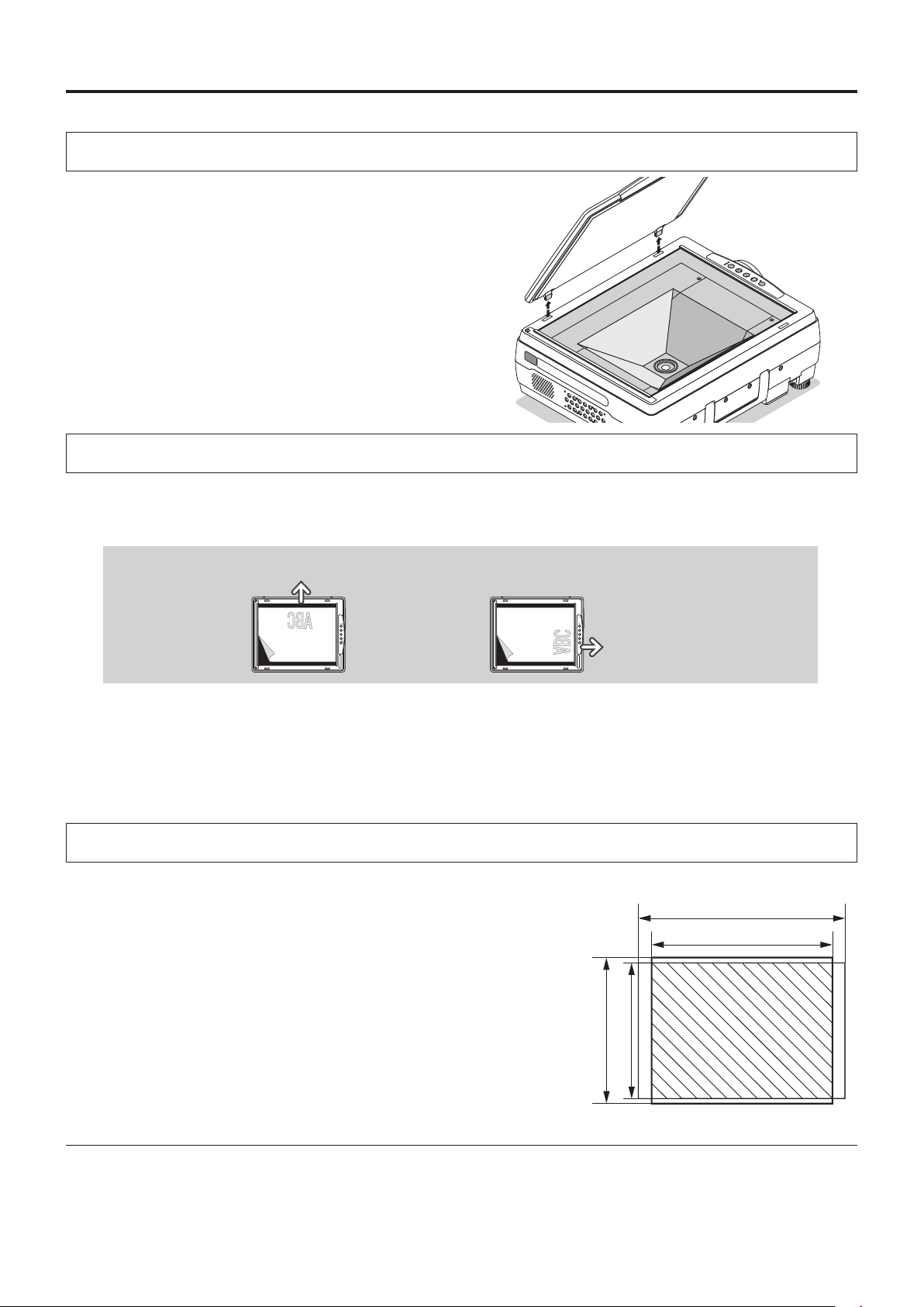
Attaching the Document Cover
The moun ting or ienta tion of the document cover can be
changed to the opposite direction in accordance with the cir-
cumstances circumstances.
NOTE:
When removing the document cover, lift the cover by
both hands and remove it.
Preparation of the Projection Document
Thedocument(printedmaterial)thatistobeprojectedisplacedontheprojectorasillustratedinthediagrambe-
low and the document cover is closed.
HorizontaldocumentTopside
Verticaldocument
Topside
NOTE:
• Thedocumentcanbeprojectedevenwhenthedocumentcoverhasnotbeenclosed;however,inthisinstance,unnecessary
items may be projected which will make the image difficult to view.
• Whenshinypaperlikemagazinecoversorblackpaperisplacedontheprojector,theinternaluorescentlight bulbmaybe
reectedinit,makingtheedgesoftheprojecteddocumenthardtosee.
Reading Size of Projection Documents
The maximum reading size of documents and printed mate-
rial is 216 mm high by 288 mm wide.
Consequently, when A4 paper (210mm highand 297.5 mm
wide)isplacedontheprojector,readingwillbeasillustrated
inthediagrambelow(whichdepictstheareathatcanbepro-
jectedastheportionwithdiagonallines).
A4 Paper
297mm(Papersize)
288mm(Readingsize)
The portion that falls outside of the reading range will not be projected;
therefore, shift the paper as required.
* When a heavy photographic object is placed, the reading size may be
reduced slightly.
210mm(Papersize)
216mm(Readingsize)
OtherfunctionsthatareusedintheOHPoperationcanbeseenonthefollowingpages:
Switching the input to OHP → See Page E-25
●
Changing the projection image to a still image display → See Page E-28
●
Capturing a projection image → See Page E-28
●
Viewing captured images → See Page E-29
●
E-33
Page 34
Menu Configuration
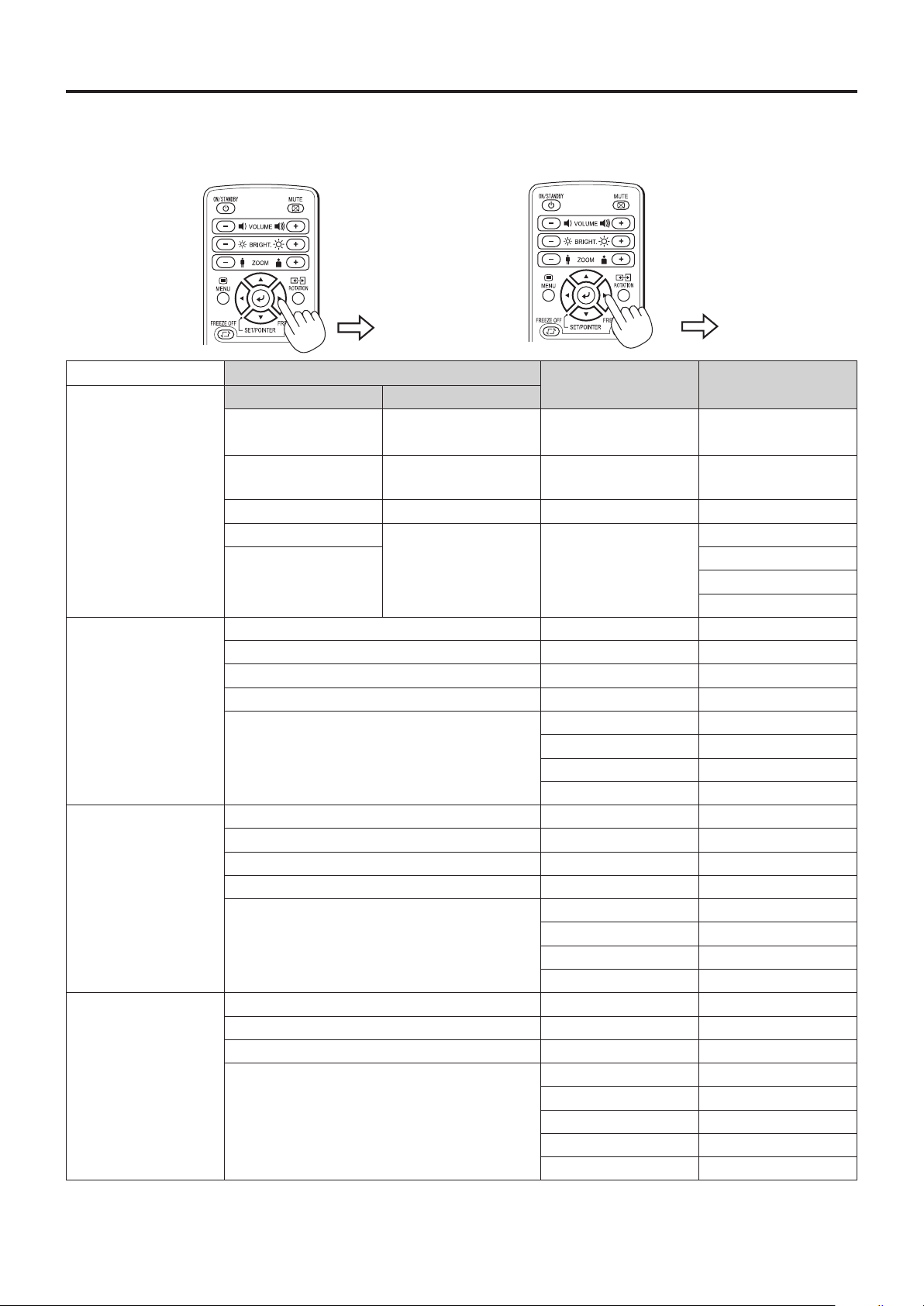
The adjustment/setting items and content will differ depending on the input selection and the permitted information
will be displayed on the menu for that input mode.
Pointer•Screen
OHP input
PCinput(RGB)
PCinput(component)
VIDEO input
Image adjustment
Pointer•Screen
Pointer
Pointer shape
Pointer color Erase entire history Blue Language selection
Pointer size Erase 1 sheet in history Color mode Projection mode
USB Format Economy mode
Pointer shape Contrast Keystone
Pointer color Brightness Language selection
Pointer size Red Projection mode
Computer input Blue Economy mode
Pointer shape Contrast Keystone
Pointer color Brightness Language selection
Pointer size Color Projection mode
Computer input Hue Economy mode
Pointer shape Contrast Keystone
Pointer color Brightness Language selection
Pointer size Color Projection mode
•Screen Historymenu
Back page in history
Next page in history
(inthesinglesheetdisplaymode)
Imageadjustment Settings
Red Keystone
Sharpness Auto power off
Aspect Ratio Lamp usage time
Color mode Input signal
Sync adjustment
Sharpness Auto power off
Aspect Ratio Lamp usage time
Color mode Input signal
Sync adjustment
Hue Economy mode
Sharpness Auto power off
Aspect Ratio Lamp usage time
Color mode Input signal
Video select
Settings
Auto power off
Lamp usage time
Input signal
NOTE:
• Thedocumentcanbeprojectedevenwhenthedocumentcoverhasnotbeenclosed;however,inthisinstance,unnecessary
items may be projected which will make the image difficult to view.
E-34
Page 35
Menu Operation Method
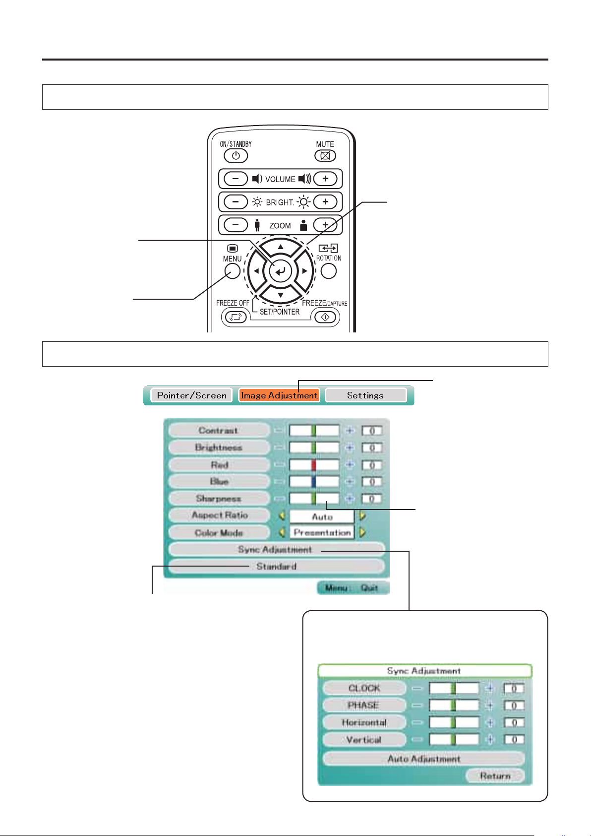
Names and Functions of the Buttons Used in Menu Operation
SET/POINTERButton
Used to finalize a setting after making
the setting or adjustment.
MENUButton
Used to display a menu and
to close a menu.
Names and Functions of the Menu Parts
SCROLL
Us e d in th e se le c ti o n of me nu
names and item names, and to set
and adjust item contents.
▲▼◀▶Buttons
Cursor(Lightblue)
Selec ts the item t hat you
would like to set or adjust.
Returns the set or adjusted item to
the standard value (shipping de-
faultconditionofourfactory).
Adjustmentbar
Indicates the adjustment condi-
tion according to the increase or
decrease of the bar point.
Submenu
When an item is selected, there will be a change-
over to the sub menu.
E-35
Page 36
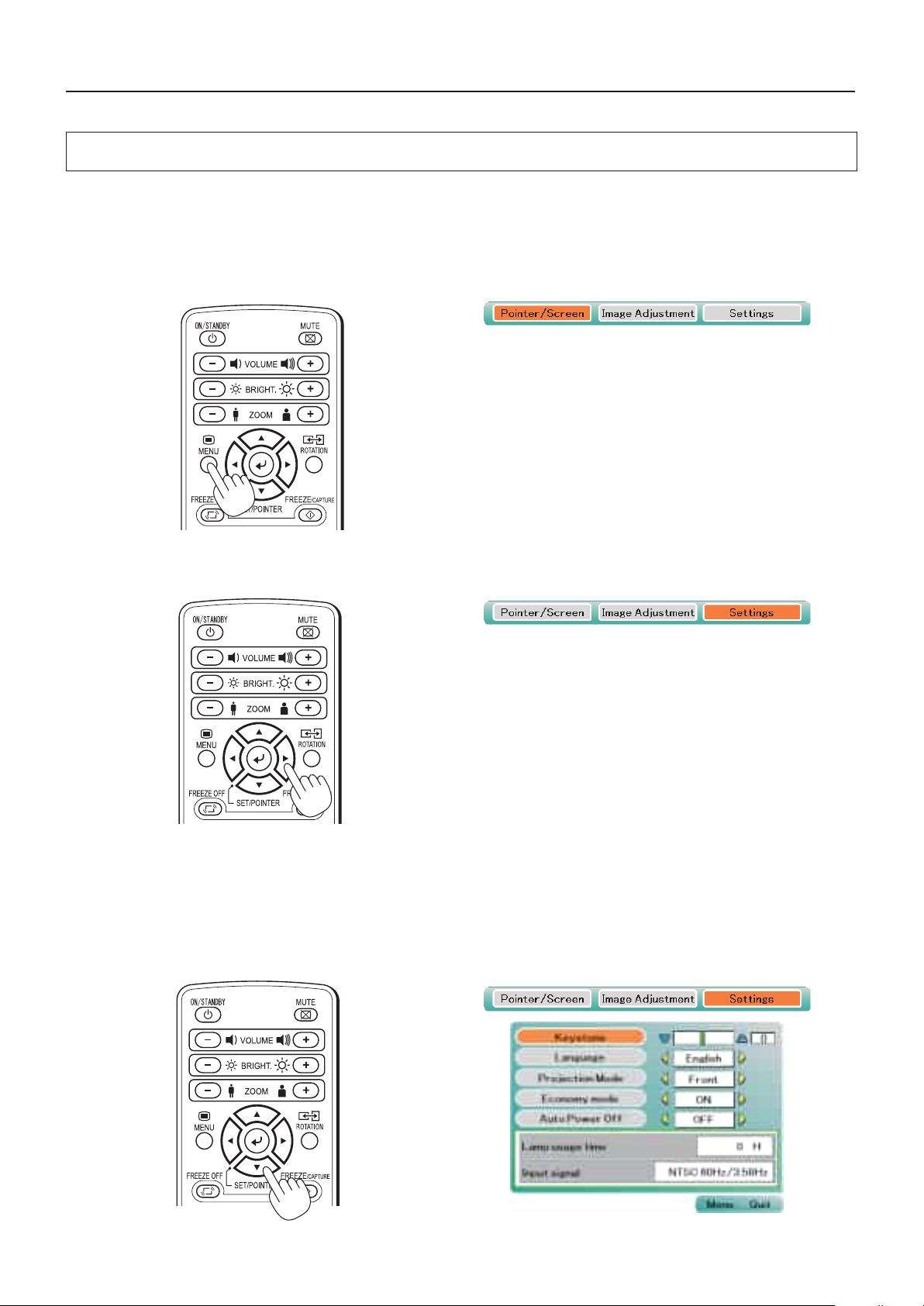
Menu Operation Method
Method of Menu Operation
This section describes the actual operation method. Adjustment of [Keystone] using the remote control is provided
as an example.
1
PresstheMENUbuttonanddisplaythemenu
2
Select[Settings]withtheSCROLL◀▶buttons
Each press of the SCROLL ▶buttonswitchesthemenuonestepinthesequenceof[Pointer•Screen]→ [Image
adjustment] → [Settings], and each press of the SCROLL ◀ button causes a return in the opposite direction.
3
Display the detailed menu with the SCROLL ▼ button or the SET/POINTER button,
thenselectKeystone.
Move the cursor and select [Keystone].
E-36
Page 37
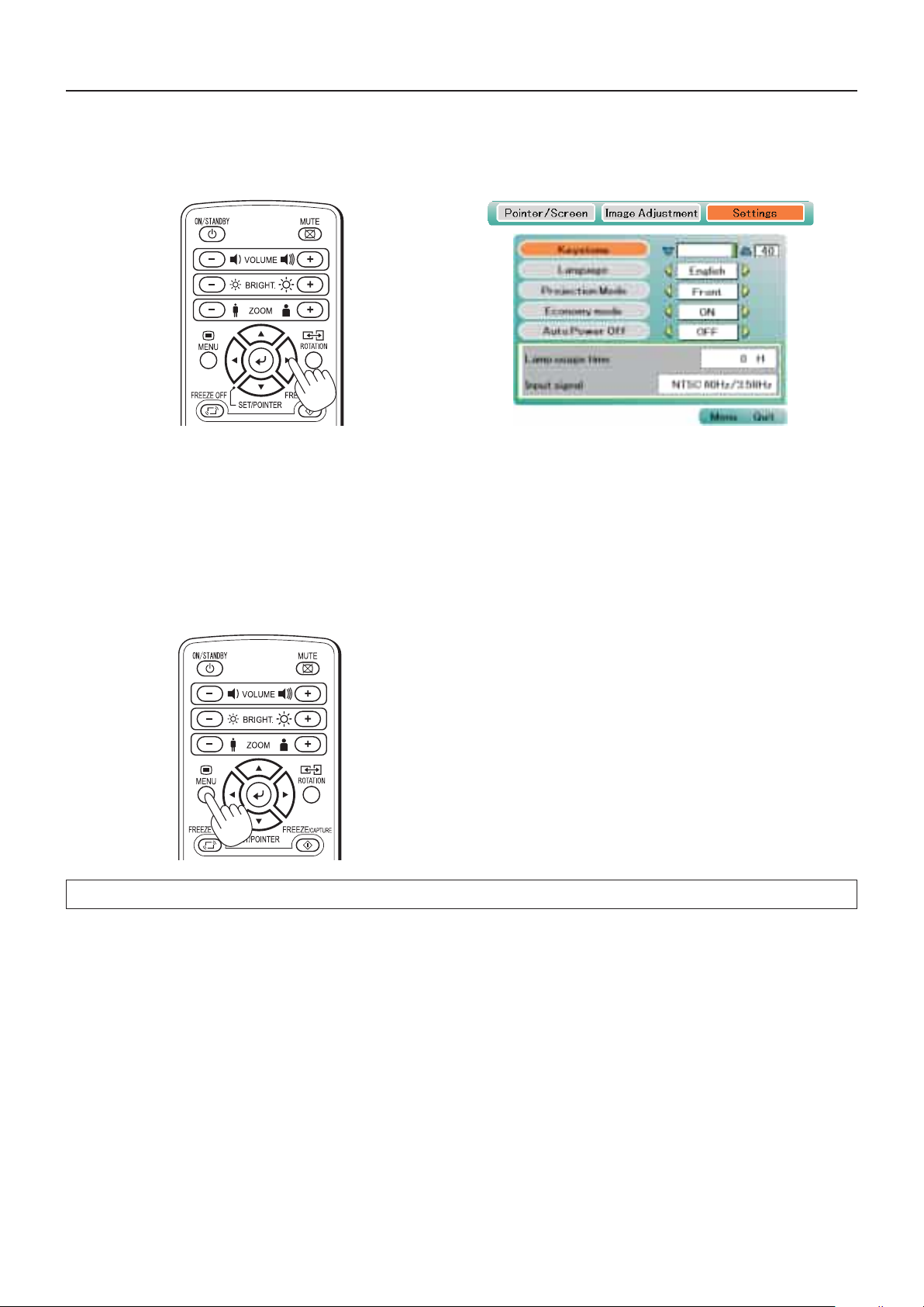
Menu Operation Method
4
Maketheadjustment withtheSCROLL◀▶buttonswhilecheckingtheprojectionim-
age
SCROLL ◀button: Each pre s s ca u s e s t h e n u m e r ical
value to decrease.
(Thelowerportionoftheprojectionim-
agebecomesnarrower.)
SCROLL ▶button: Each pre s s ca u s e s t h e n u m e r ical
value to increase.
(The upper portion of the projection
imagebecomesnarrower.)
5
PresstheMENUbuttonandclosethemenu
Thiscompletesthe[Keystone]adjustment.
E-37
Page 38
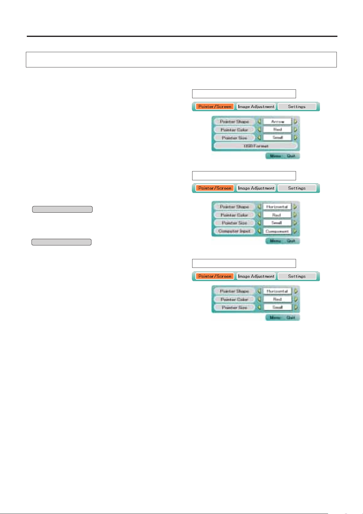
E-38
Menu Description
Pointer • Screen
This selects the shape, color, and size of the pointer.
Pointer shape .................. Select the form of the pointer from
among 2 types, Arrow and Horizon-
tal.
Pointer color .................... Selects the color of the pointer from
amongst 3 types (i.e., red, white,
andblue).
Pointer size ......................Thesizeof the pointer (i.e., Large,
M e di u m , an d Sm a l l ” c a n b e
changed in 3 levels.
USB Format ..................... All of the data in the USB memory
stick will be deleted.
* Only for iP-01UE.
Computer input ................Selec t the i nput s i gnal ( RGB or
componentvideo).
RGB: Use this to project images on
a computer.
Component*: Use this when pro-
jecting the video of videos D1 to
D4.
OHP input only
During PC/Component video input
During Video input
During OHP input
OHP input only
Page 39
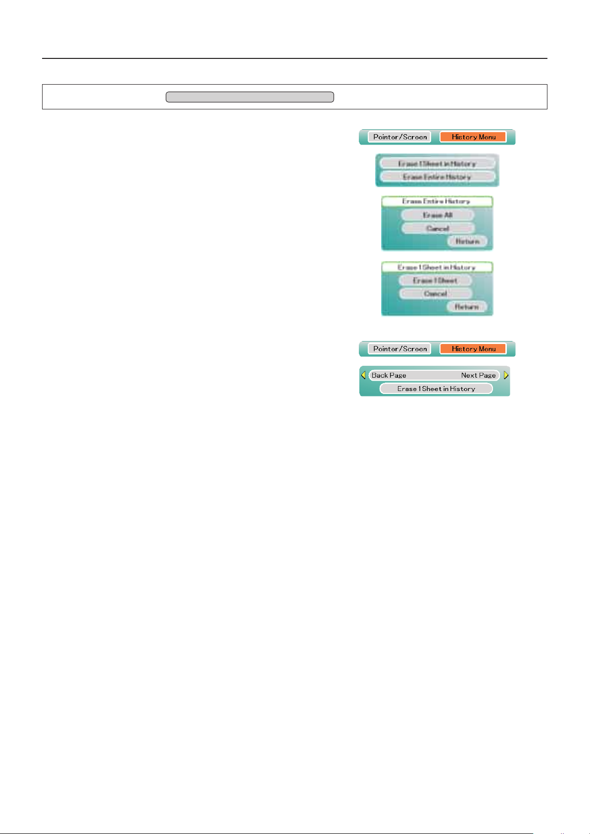
E-39
Erase entire history .........The verification screen will be dis-
played. Select “Erase All” and then
pressing the SET/POINTER button
will delete all of the data in the fold-
er in which the currently displayed
file has been saved. Other folders
will not be deleted.
Erase 1 sheet in history ...The currently displayed history im-
age is deleted and the next history
image is displayed.
The following items will be displayed only during the projection
of displayed images that were selected from the USB memory
stick.
Back page in history Next page in history
Set the cursor then use the ◀ but-
ton on the remote control unit to se-
lect “Previous history image”, the ▶
button to select “Next history image”.
Backpage in history: The projec-
tor switches to the histor y image
stored in the memor y befo re the
currently projected history image.
Nextpageinhistory: The projector
switches to the history image stored
in the memory after the currently
projected history image.
* Only for iP-01UE.
Menu Description
History menu *
Only when inserting the USB memory stick
Page 40
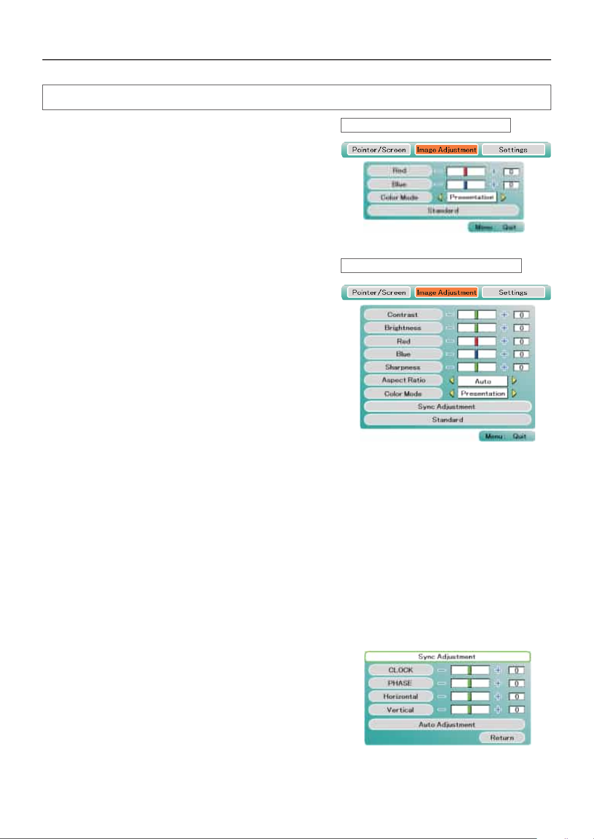
E-40
Menu Description
Image adjustment
This performs the settings and adjustments related to the projected
image.
When OHP input has been selected.
Red
(Redcoloradjustment) ........ Adjusts the deepness of the red color in the
range of -50 to 50.
Blue
(Bluecoloradjustment) ........ Adjusts the deepness of the blue color in the
range of -50 to 50.
When PC input (RGB) has been selected
Contrast ...........................Adjusts the contrast of the projected image in
the range of -50 to 50.
Brightness .......................Adjusts the brightness of the projected image
in the range of -50 to 50.
Red
(Redcoloradjustment) ........ Adjusts the deepness of the red color in the
range of -50 to 50.
Blue
(Bluecoloradjustment) ........ Adjusts the deepness of the blue color in the
range of -50 to 50.
Sharpness ....................... Adjusts the sharpness of the projected image
in a range from -50 to +50.
Aspect Ratio ....................Switches the aspect ratio of the projected im-
ageto4:3or16:9.Whenautomaticdetection
has been selected, the aspect ratio will be
switched in accordance with the input.
Color mode
Standard ..........................The contrast is strong and the image is crisp.
Presentation ....................Displays in a color that suits the presentation.
Natural .............................The images are projected with colors near
those of the original image.
Blackboard ......................Use this when projecting images on a black-
board.
Sub menu: Sync adjustment
Clock ...............................Adjusts the horizontal size of the projected im-
age in the range of -50 to 50.
Phase .............................. Adjusts the noise/flickering of the projected
image in the range of 0 to 31.
Horizontal ........................
Adjusts the horizontal position of the projected im-
age in the range of -50 to 50.
Vertical .............................
Adjusts the vertical position of the projected image
in the range of -50 to 50.
Auto adjustment ...............
Performs sync adjustment automatically.
NOTE:Depending on the PC input signal, there might not be a change as far as from -50 to 50.
During OHP input
WhentheinputissettoPC(RGBselected)
Page 41
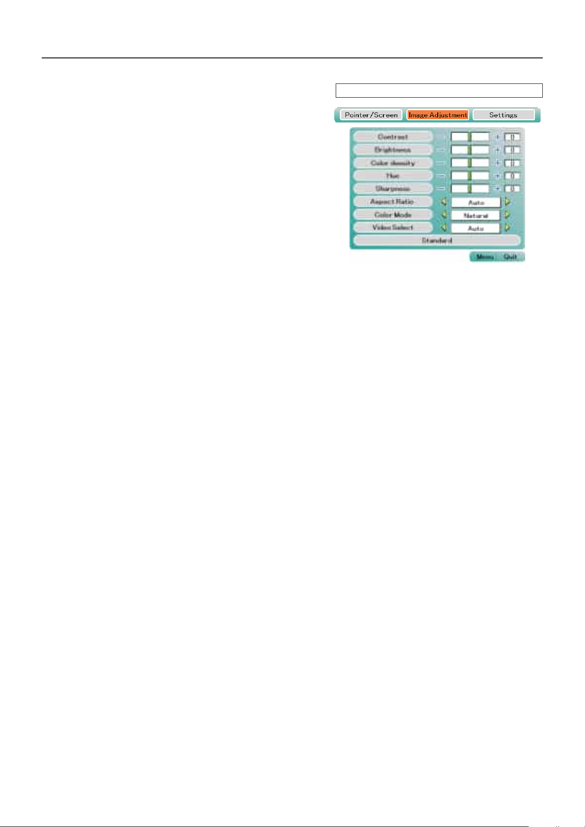
E-41
When the PC (component) input or the VIDEO in-
put is selected
Contrast ...........................Adjusts the contrast of the projected im-
age in the range of -50 to 50.
Brightness .......................Adjusts the brightness of the projected im-
age in the range of -50 to 50.
Color ................................Adjusts the deepness of the color in the
range of -50 to 50.
Hue ..................................Adjusts the hue in the range of -50 to 50.
As the numerical value becomes lower,
the color becomes greenish and as the
numerical value increases, the color be-
comes reddish.
Sharpness ....................... Adjusts the sharpness of the projected im-
age in a range from -50 to +50.
Aspect Ratio ....................Switches the aspect ratio of the projected
imageto4:3or16:9.Whenautomaticde-
tection has been selected, the aspect ratio
will be switched in accordance with the
input.
Color mode
Standard ..........................The contrast is strong and the image is
crisp.
Presentation ....................Displays in a color that suits the presenta-
tion.
Natural .............................The images are projected with colors near
those of the original image.
Blackboard ......................Use this when p ro jec tin g im age s on a
blackboard.
Sub menu: Video Select (only valid when the in-
put is set to VIDEO)
This selects the input signal system.
Auto(detects the signal system automatically) / NTSC 3.58 /
NTSC 4.43 / SECAM / PAL B, G, H, I / PAL M / PAL N
Menu Description
WhentheinputissettoPC(componentselected)
Page 42
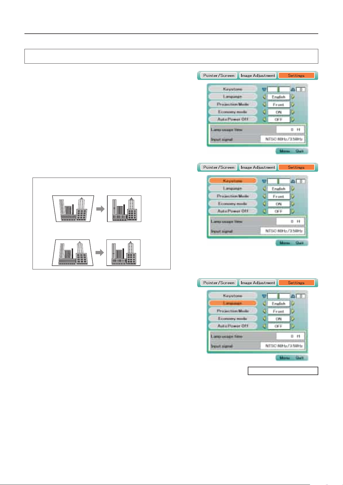
E-42
Settings
Menu Description
This performs settings related to the projector unit or while
the projector is in use.
Lamp usage time .............D i s p l ays the usage ti m e of the
lamp.
"ReplacementoftheLampUnit"→ See Page E-46
Input signal ......................The name of the currently selected
input is displayed.
Setting Items
Keystone ..........................Performs keystone correction of the
projection image.
NOTE:
• When keystonecorrectionhasbeen applied, theresolutionat the screenedgeswill degradeandsmallcharactersandthe likewillbecome
difficult to see. When you do not wish to have the resolution degradation, set the projector on a level platform and set the numerical value of
theKeystonemenuto"0"(nocorrection).
• Compared towhenkeystonecorrectionis not applied, the application of keystonecorrection resultsinadisplayimage (of characters,etc.)
that appears somewhat blurred and this is related to the image processing that is performed.
• Keystone(correction)willhaveadifferentadjustmentrangedependingonthedisplayedimagesignal.
Language selection ......... Selects from among the following
languages the language for use in
the menus and mess age indica-
tions: Japanese, English, French,
German, Spanish, Italian and Chi-
nese.
Continued on the next page
As the numerical value increases, the upper portion of
the projection image becomes narrower.
As the numerical value decreases, the lower portion of
the projection image becomes narrower.
Page 43
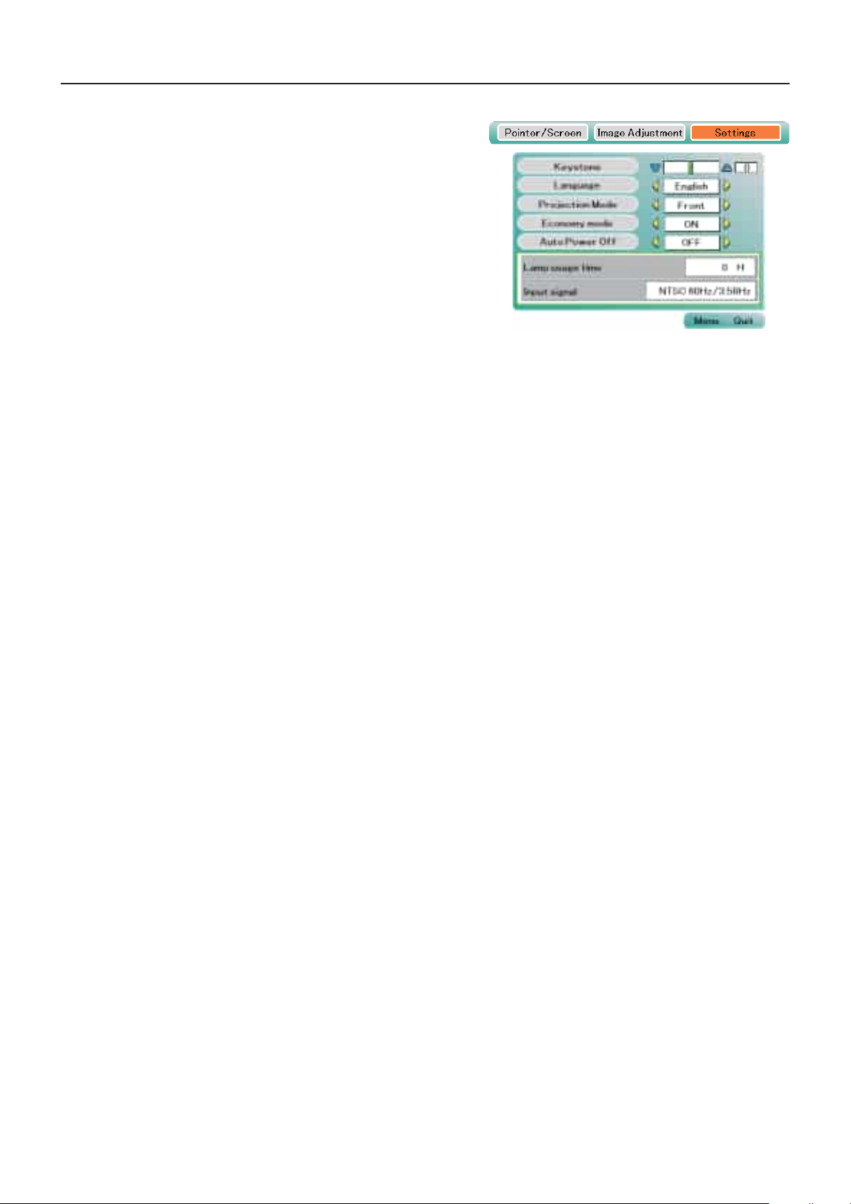
E-43
Projection mode ...............Selects the projection system of the
projectorfrom betweenFront(front
projection) and Rear (rear projec-
tion).
Economy mode ...............ON:
The brightness of the lamp will be
approximately 90%. The lamp ser-
vice life will be extended.
OFF:
The brightness of the lamp will be
100%. There will be a bright screen.
* As the default, Eco mode is set to ON.
Auto power off ..................When this is set to “ON”, the lamp
turns off if the projector is in the “No
Sync” mode for 15 minutes when
the input is set to PC/component
video or VIDEO.
Menu Description
Page 44
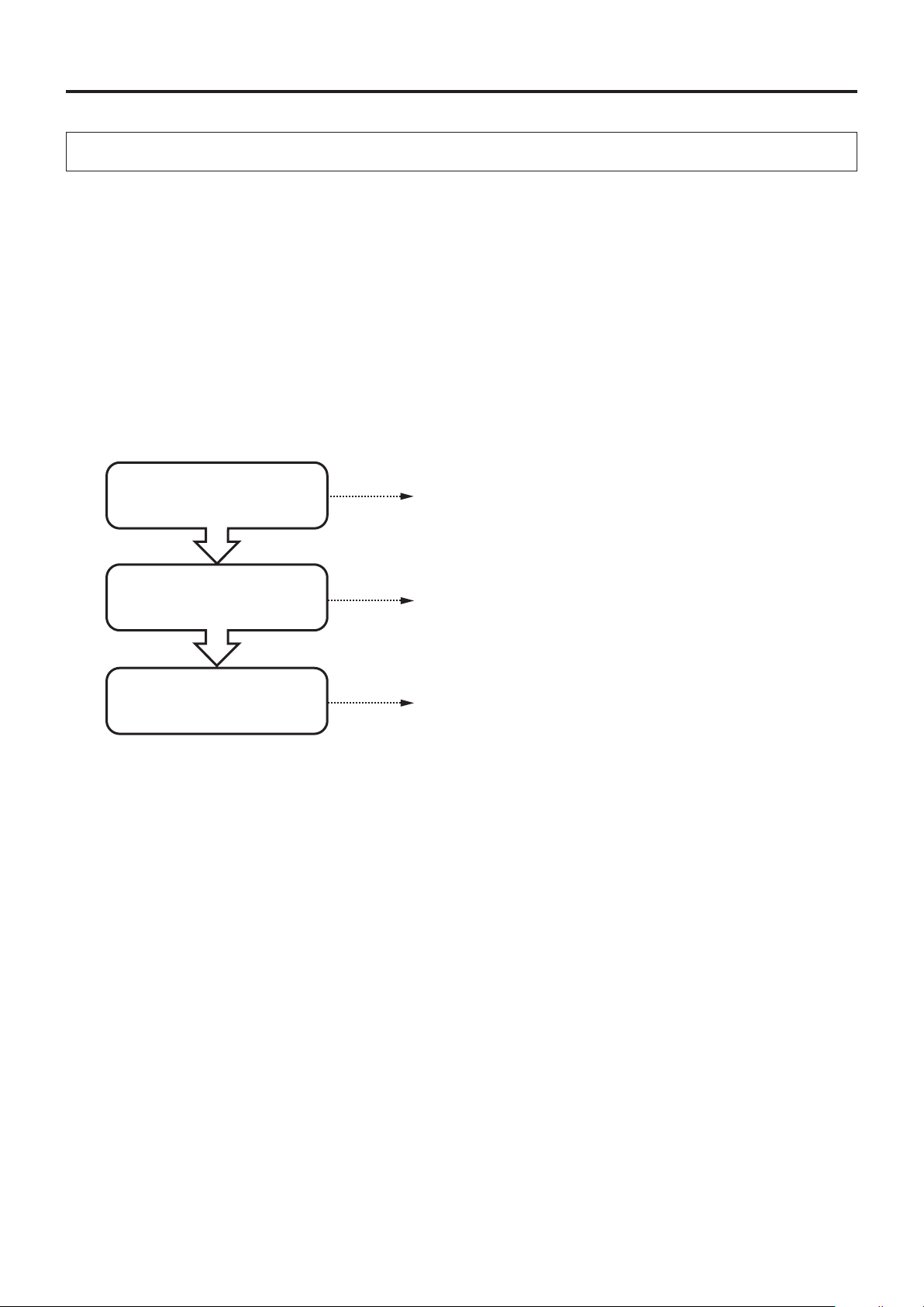
E-44
Maintenance
The projector is equipped with a built-in protection circuit to prevent re and breakdown due to faults.
When the LAMP/COVER LED lights in red
Measurestobetaken
1. Disconnect the power plug from the outlet.
2.Properlyinstallthelampunitcover.See"ReplacementoftheLampUnit"onPageE-46.
When the TEMP LED flashes or lights steadily
Measurestobetaken
1. Disconnect the power plug from the outlet.
2. Check the following matters and perform the countermeasure properly.
Fault Protection
Is the ambient temperature
inexcessof35°C(95°F)?
Please use the projector in an operation ambient temperature
of0°C(32°F)to35°C(95°F).
Are the ventilation vents
blocked?
Rearrange the setup location of the projector and separate the
projectorfromsurroundingobjects.See "Do Not Block theair
vents"onPageE-4.
Breakdown of an internal cir-
cuit could be the problem.
Please request repair at your dealer of purchase.
* The projector is running properly when the TEMP LED turn off.
* When the LAMP/COVER LED is lit red at the same time, please replace the lamp. See Page E-46 for information about
the replacement method.
* TheashingoftheTEMPLEDisawarningofahightemperature.
Whenthe usage circumstanceshave not changedafter10seconds haveelapsedsince the start ofthe ashing,the
TEMP LED changes to be lit steady and the lamp goes off.
Page 45
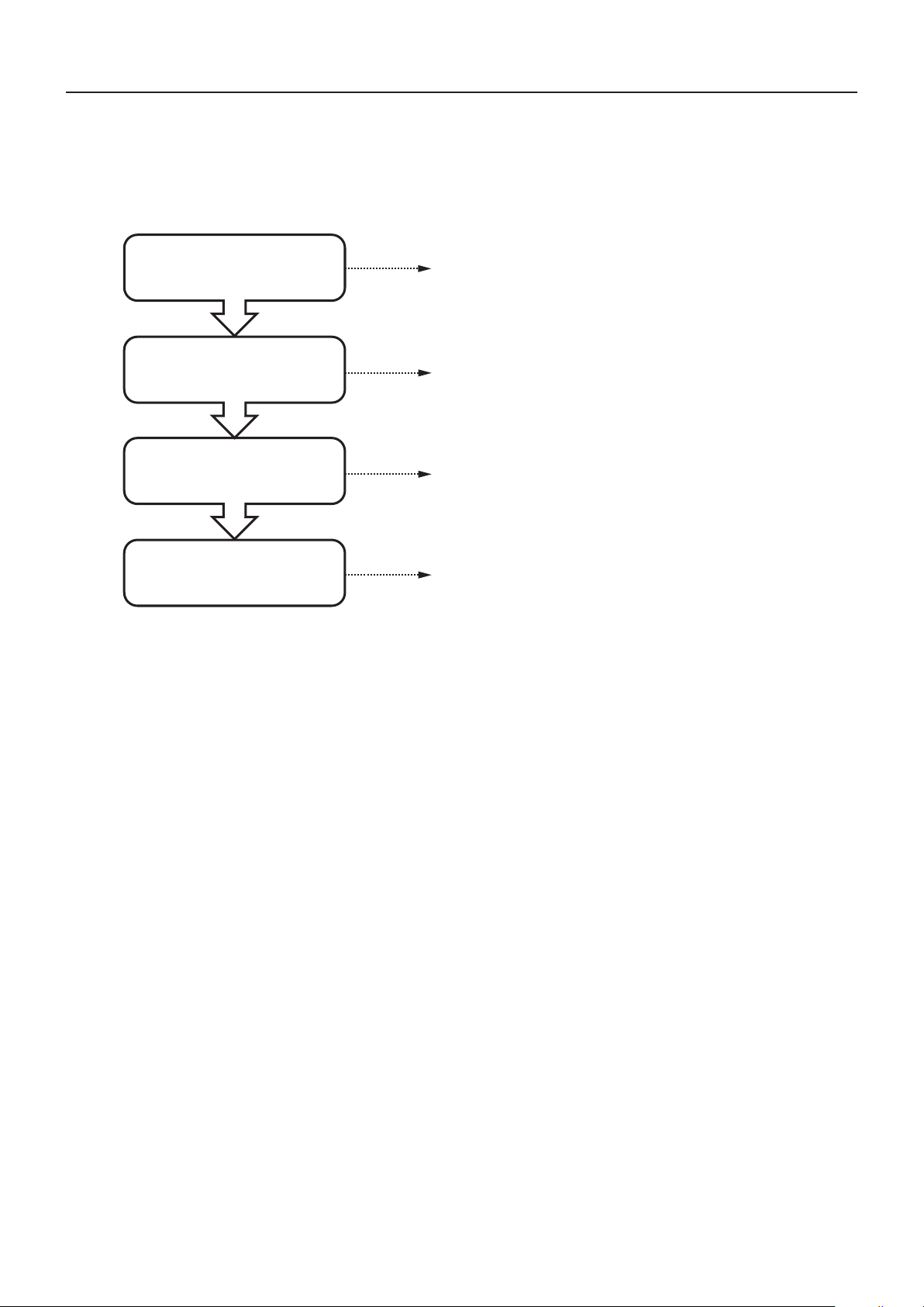
E-45
When the power has failed (When all the LED go off with the power ON)
Measurestobetaken
1. Disconnect the power plug from the outlet.
2. Check the following matters and perform the countermeasure properly.
Maintenance
Is the ambient temperature
inexcessof35°C(95°F)?
Are t h e vent i lati o n vent s
blocked?
Are the Air Intake/Ventilation
Slotsblocked?
Breakdown of an internal cir-
cuit could be the problem.
Please use the projector in an operation ambient tempera-
tureof0°C(32°F)to35°C(95°F).
Rearrange the setup location of the projector and separate
theprojectorfromsurroundingobjects.See "Do NotBlock
theairvents"onPageE-4.
Please request repair at your store of purchase.
Clean the Air Intake/Ventilation Slots
See "Cleaning the Air Intake/Ventilation Slots " on Page
E-49.
Page 46
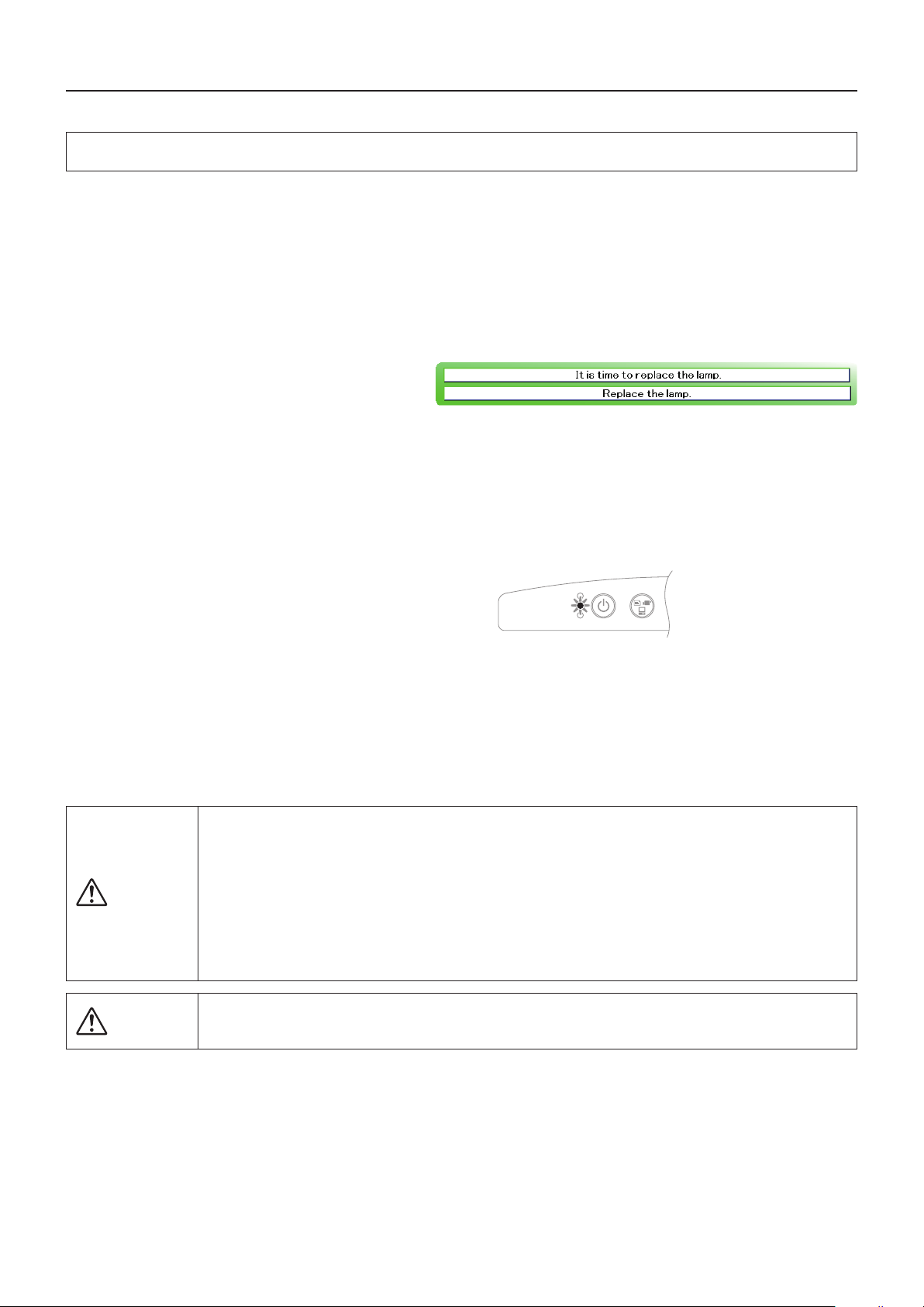
E-46
Replacement of the Lamp Unit
Theprojectionlampusedonthis projectorshouldbe replacedafteraboutthenumberof hoursindicatedbelow(orsooner,de-
pendingontheusageconditions).
When the usage time exceeds 2000 hours*, the possibility for explosion increases, so the lamp is forcibly shut off.
Whentheusagetimeexceeds1900hours,replacethelampunit(soldseparately)beforetheusage timereaches2000 hours.
Also, if the picture is dark, the lamp has reached the end of its service life. Replace it with a new lamp unit.
Whenthelampusagetimereaches1900hours
-Messageprojectedbytheprojector-
This is displayed when the lamp usage time exceeds
1900 hours.
-Mainunitcontrolpanel–
Thelamp/coverLEDashesred.
The lamp usage time can be checked at the “Installation settings” menu.
Whenthelampusagetimeexceeds2000hours
-Messageprojectedbytheprojector–
The lamp does not light and nothing can be projected.
-Mainunitcontrolpanel–
The lamp/cover LED lights red.
* The “Lamp usage time” that is displayed on the menu screen displays the usage time when the Eco mode is both ON and OFF
as a value converted to usage time when the Eco mode is OFF.
It is for this reason that when the projector has been used with the Eco mode always ON, the lamp replacement time guideline
will be at a lamp usage time of 1900 to 2000 hours on the menu screen, although the guideline for lamp replacement is 2900
to 3000 hours in terms of the actual usage time.
Maintenance
• Donotreplacethelampunitimmediatelyafterusingtheprojector.
The lamp is high temperature and you could get burned. Disconnect the power plug from the outlet
and wait one hour or longer before replacing the lamp.
• Donottouchtheglassportionofthelampunitwithyourhands.Doingsocouldlowerthebrightness
and shorten the life of the lamp.
• Thereisalargenumberofglasspartssuchasthelampandmirrorsthatareusedinsidetheprojec-
tor. If a glass part breaks, please exercise due caution in handling so that you are not injured by frag-
ments. Please request repair from the store of purchase.
WARNING
• Pleasespecifythededicatedlampunit(Model:IPLK-J1).
CAUTION
ON/STANDBY
TEMP
INPUT
LAMP/COVER
Page 47
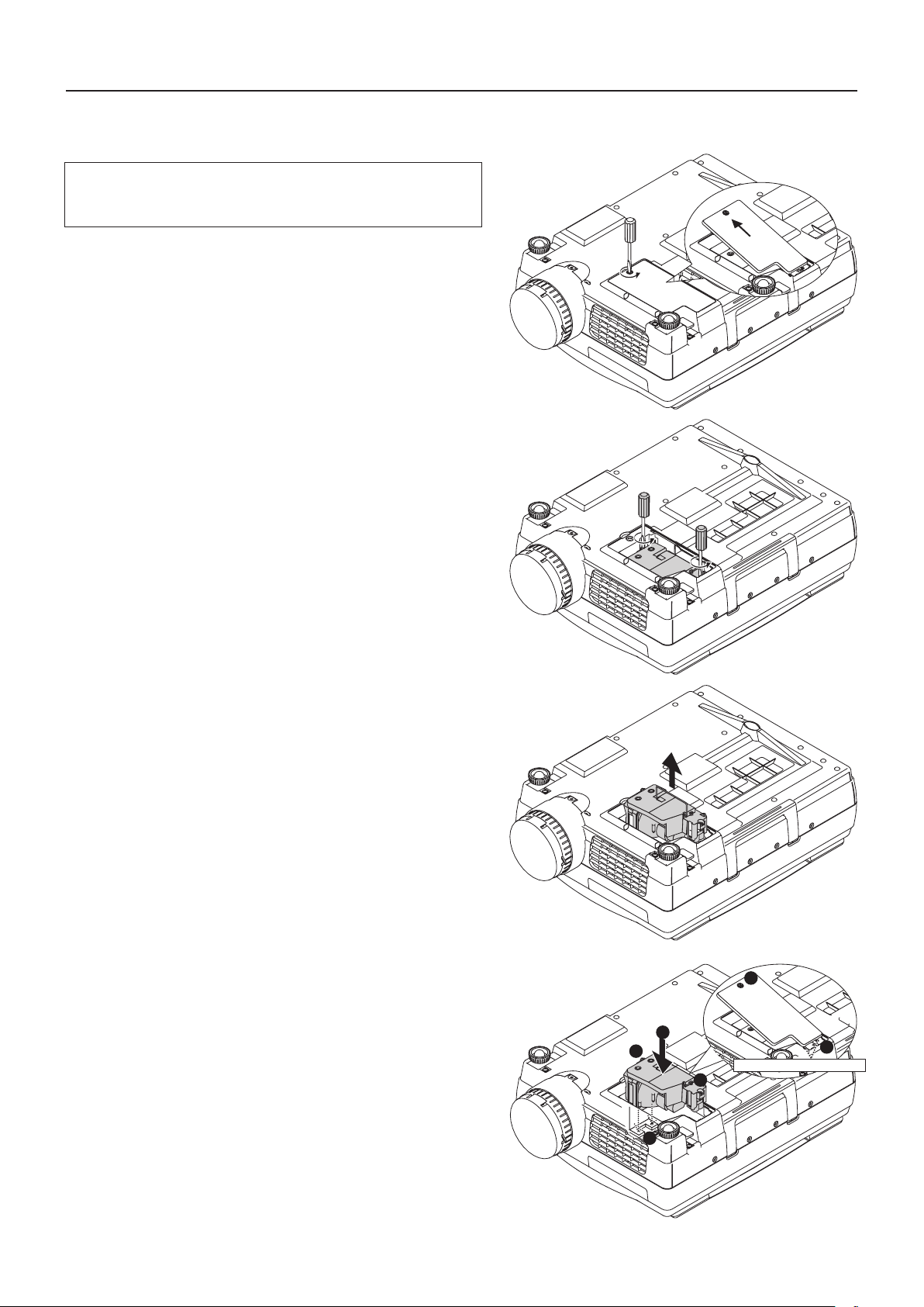
Lamp Unit Replacement Procedure
Topreventburns,waitonehourorlongerafterthelamphas
been switched off before performing the following proce-
dure.
1
Removethelampunitcover
Using a minus screwdriver, loosen the screws of the
lamp unit cover, pull in the direction of the arrow, and re-
move the cover.
2
Loosenthemountingscrewsofthelampunit
Using a minus screwdriver, loosen the 2 screws of
the lamp unit.
Maintenance
3
Pulloutthelampunit
Hold the handle of the lamp unit and pull it up and out.
4
Installanewlampunit
❶ Take the lamp unit and press it into the projector.
❷ Check that the two positioning prongs on the bottom of the
lamp unit are securely t into the two holes.
❸ Tighten the 2 mounting screws of the lamp unit.
❹ Align the 2 tabs located on the lamp unit cover with the
projector and attach from the side of the tabs. Tighten the
mounting screws of the lamp unit cover.
4
1
3
Positioning protrusions
3
2
4
ツメ
E-47
Page 48
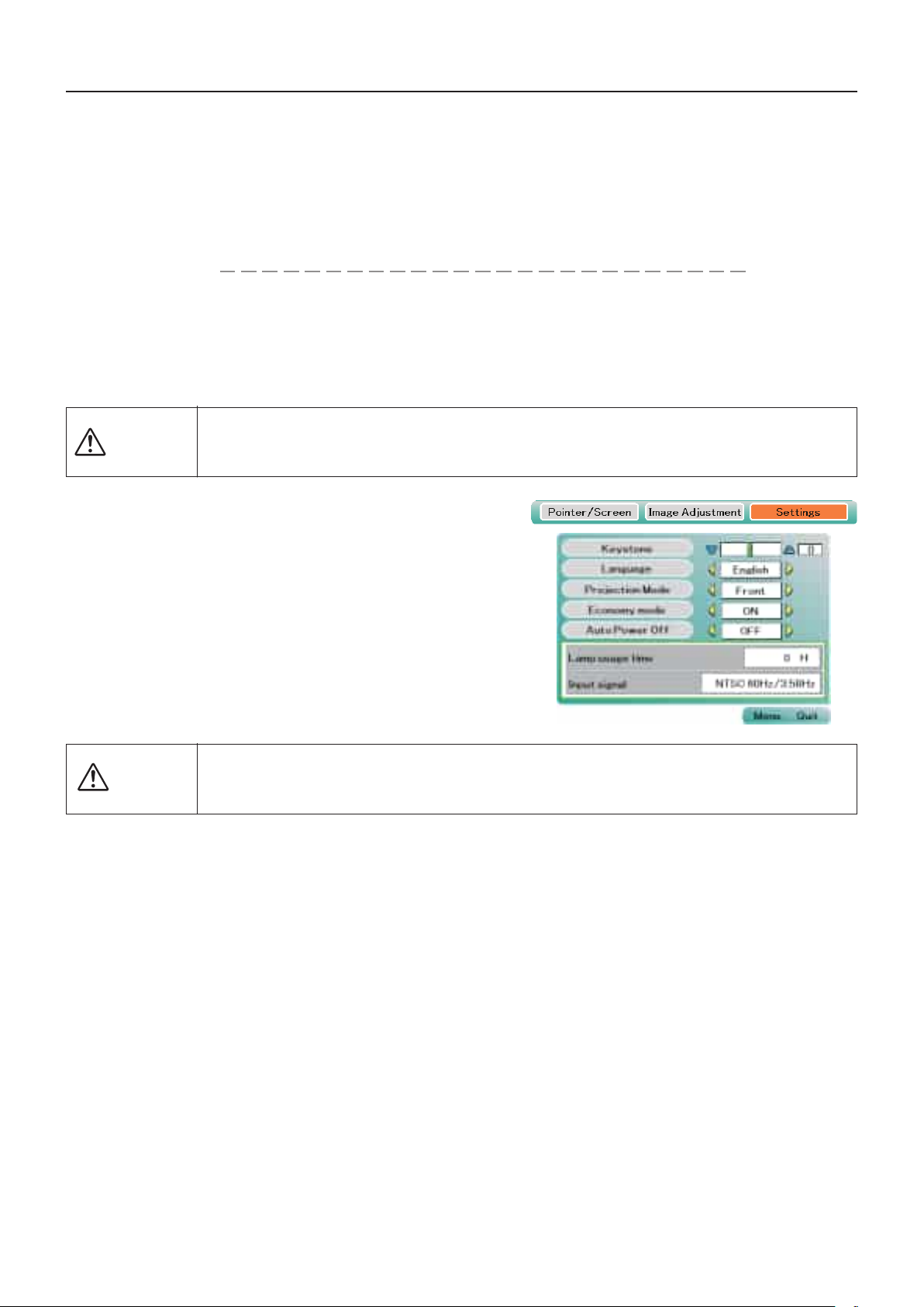
E-48
Maintenance
5
Resetthelampusagetime
Please perform the operation indicated below in the standbymode(*).
6
Checkthat theindication of the lampus-
agetime hasbecome "0 H"as illustrated
inthediagramtotheright.
If the usage time has not been reset, please reset it by
following Step 5 again.
Check the lamp usage time by pressing the menu button of
the remote control to display the menu, then use the scroll
◀▶ button to display the setup setting.
OperationwiththeProjector
PresstheINPUT,PORTRAIT,FREEZEOFFandFREEZE/CAPTUREbuttonssimul-
taneously, then press the input selector and still picture buttons simultaneously.
OperationwiththeRemoteControl
Resetting of the lamp usage time cannot be performed with the remote
control.
TheLAMP/COVERLEDwillashgreenfollowingthisandprojectionwillstart.
* The power plug is plugged into a power outlet and only the ON/STANDBY LED is lit red.
• Donotresetthelampusagetimewithoutreplacingthelamp.
The likelihood of the lamp rupturing becomes higher when the lamp has been used in excess of
2000 hours.
CAUTION
If the lamp is used without resetting the usage time, the correct lamp usage time will not be known;
therefore, be sure to reset the usage time after lamp replacement. When the indication exceeds 2000
hours, the projector will be forced to turn off the projection lamp.
CAUTION
NOTE:
• Intheinterestofsafety,thelampwillnotlightwhenthelampunitcoverisoff.
• Inregardtothedisposalofthelampunit,followthedisposalmethodofyourmunicipalityforthesametypeofwasteascom-
monhouseholduorescenttubes.
Page 49
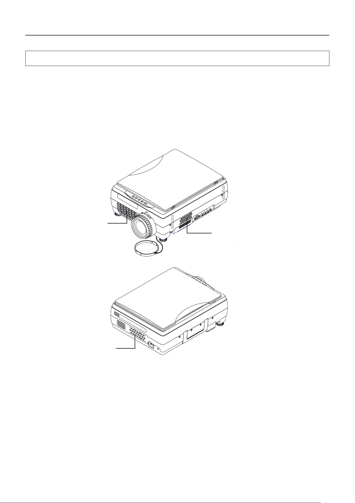
Maintenance
Cleaning the Air Intake/Ventilation Slots
The air intake/ventilation slots serve as the way in and out for the air that cools the internal heat of the projector. Depending on
theowoftheair,dustmaycollectwhileyouareusingtheprojector.Whendustcollects,the internal temperaturewill rise and
the rotation of the fan will also increase which will cause a drop in the life of the product or breakdown; therefore, please clean
theprojectorregularly(ontheorderofonceeverymonthbasedon4hoursofuseperday).
Location and Cleaning Method of the Air Intake/Ventilation Slots
Cleanthethreelocationsdescribedbelowwithavacuumcleaner.
Frontventilationslots
Rearairintakeslots
A
SideairintakeslotsB
C
E-49
Page 50
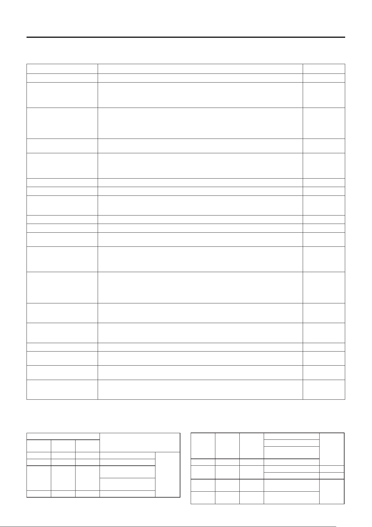
E-50
Troubleshooting
When you think the projector may be out of order, please rst check the following matters before requesting repair.
Symptom Pleasecheckthis
Referencepage
Power does not come on • Isthepowercableconnected? E-23
Pro j e c tion la m p does not
light
• Isthelampunitcoverinstalled?
• Is the internaltemperaturehigh? If so,thelampwillnotlighttoprotectthe projector
from damage.
• Isthelampusagetimeinexcessof2000hours?
E-47
E-44
E-48
There is no image • Hastheconnectedinputbeenselected?
•
Isthecableoftheconnectedequipmentproperlyconnected?
• Have "Brightness" and "Contrast"of the "Image adjustment" menu been set all the
waytotheminusside?
• Haveyoucheckedthefunctionsofthepersonalcomputer?
E-25
E-18, 22
E-40
E-20
Image is distorted • Istheprojectorsetupproperly?
• Haskeystonecorrectionbeenapplied?
E-16
E-42
Image is blurred • Hasthefocusbeenadjusted?
• Istheprojectiondistancewithintherangethatcanbeproperlyfocused?
• Haskeystonecorrectionbeenapplied?
• Isthelenscapattached?
E-24
E-17
E-42
E-10
Theimageickers • Pleaseadjust"Phase"ofthe"Syncadjustment"menu. E-40
The image is out of adjustment
• Arethesettingsofthe"Syncadjustment"menusuitable? E-40
The image wavers
• Dependingontheinstallationenvironment(e.g.,besideawallorwhenaffectedbyair
conditioningaircurrents),thehotairexpelledfromthefrontmaycauseheathazeand
the projection image may waver.
−
The color is not right • Pleaseadjust"Phase"ofthe"Syncadjustment"menu. E-40
There is no sound • Isthevolumeadjustmentsettotheminimum? E-31
There is a snap sound
from the cabinet
• Thissoundisassociatedwiththeminuteexpansionorshrinkageofthecabinetduetoa
change of the temperature. It has no effect on performance or anything else.
−
The remote control will
not work
• Isthebatteryexhausted?Orisitweak?
• IstheremotecontrolIRsensorexposedtoilluminationorotherlight?
• IstheremotecontrolIRsensorblocked?
• Isaninverterdevicelocatedcloseby?
E-4, 15
E-15
E-15
E-15
At the time of personal
computer input selection,
the position of the video
is shifted, or the display is
compressed
• Pleaseadjustusingthe"Syncadjustment"menu. E-40
“USB memory is not
formatted.” Is displayed.
• UnplugtheUSBmemorysticktemporarily,thentryreinsertingit2or3secondslater.
If there is no improvement, use the PC to perform formatting in the FAT 32 format.
After this, try reinserting the USB memory stick again.
E-38
E-12
The USB memory stick
cannot be accessed normally
• IstheUSBmemorystickbroken?
Check whether the USB memory stick can be used with another device.
(ThisdoesnotguarantytheoperationofallUSBmemorysticks.)
−
The TEMP LED lights • Followtheinstructionsonthe"FaultProtection"measurespage. E-44
The LAMP/COVER LED
lights in red
• Isthelampunitcoverdisengaged?
• Isthelampusagetimeinexcessof2000hours?
E-47
E-48
The LAMP/COVER LED
lights in orange
• Thereisaprobleminsidetheprojector.Pleasecontactthedealer.
• Sinceanabnormalityisfoundintheinternalpart,requestrepair.
E-51
The data stored on the USB
mem o r y st i ck ca n n o t be
viewed with iP-01
• UnplugtheUSBmemorysticktemporarily,thentryreinsertingit2or3secondslater.
If there is no improvement, please check the USB memory stick.
−
NOTE:
Fortheadditionalinformation,visitourwebsite(http://www.avio.co.jp)
LED List
LED State
Significance
ON/
STANDBY
LAMP/
COVER
TEMP
Off Off Off AC power OFF
Normal
condition
Red Off Off Standby
Green
Flashing
green
Off
Standby to start of projection
End of projection to
standby
Green Green Off Projecting
Red Red Off
Lamp cover open
Power
has been
switched
OFF
because of
the alarm
Lamp burned out
Lamp usage exceeds
2,000 hours
Red Orange Off Internal problem
Red Off Red
Temperature fault
Fan fault
Green
Flashing
red
Off
Lamp usage exceeds
1,900 hours
Alarm
sounding
Green Green
Flashing
red
Abnormal temperature
warning
Page 51

E-51
Repair Service Procedure
• Duringthewarrantyperiod,wewillrepairtheproductinaccordancewiththewarrantyregulations.Pleaserequestserviceat
your store of purchase.
Please submit the written warranty at the time of your request.
• Pleasecontactyourstoreofpurchaseforrepairsthatfollowtheelapsedwarrantyperiod.
When repair work enables the maintenance of product functions, charges will apply. for the repairs.
• Beforeaskingforrepairservice,checktheTroubleshootingsectiononpageE-50oncemore.Ifthischeckconrmsaproblem,
contact the dealer where you bought the product.
• Whenaskingforrepairservice,provideyourdealerwiththefollowinginformation:
Descriptionoftheproblem(asmanydetailsaspossible)
Date of purchase
Your Name
Your Address
Telephone number
Product name and model No.
Repair Service
Page 52
E-52
Specifications
Model Name iP-01U
Type Single-plate DLP ® color wheel color separation type
Main Part
Specication
DLP ® chip
Size 0.55”DLP®chipx1,aspectratio4:3
Number of Pixels 786,432pixels(1,024x768dots)
Projection Lens F2.6 to 2.9, f = 25.8 to 30.0 mm, zoom ratio 1.2
Optical Source 260W Super High-pressure Mercury Lamp
Image Size 33-300inchesdiagonal(projectiondistance0.67to6.1m)
Color Reproducibility Fullcolor(16,770,000colors)
Brightness 2500 ANSI lumens
ScanFrequency(analogRGB) Horizontal 24.8 to 91.1 kHz, Vertical 50 to 85 Hz
Maximum Resolution At RGB signal input 1,024x768dots(Compresseddisplayof1600x1200dotsispossible.)
Video Input
OHP(actualobject
projectionunit)
Scanner 3.15 million pixel color CMOS
Scanning size 288mmx216mm(11.3inx8.5in)
PC
(AnalogRGBInput)
Signal system Separate Signal System
Video signal Analog:0.7Vp-p/75Ω
Sync Signal
Separate/composite:TTLLevel(positive/negative)
Syncongreen:0.3Vp-p(Negative)
Terminal Panel 15 pin Mini D-sub 1 ch
Video
Signal system NTSC/PAL/SECAM/PAL-N/PAL-M/NTSC4.43
Input Terminal RCA Pin Jack 1 ch
Component
video input *
1
Signal system
Y:Y:1.0Vp-p/75Ω(withsync),Cb-Cr:0.7Vp-p/75Ω
D1/D2/D3/D4
Input Terminal 15-pin Mini D-SUB x 1
Audio Input
PC
Audio Signal 0.4Vrms/47KΩ
Input Terminal RCA Pin Jack 1 ch
Video
Audio Signal 0.4Vrms/47KΩ
Input Terminal RCA Pin Jack 1 ch
PC/Video/component
video *
1
Audio Signal 0.4Vrms/47kΩ
Input Terminal RCA(L/R)pin-plugjackx1
Image File Format ExitJPEG(2048x1536dots)
Memory interface USB memory*
2
/slot(USB2.0)
Audio Output 5W monaural
Operating Range of Temperature and Humidity Temperature:0to35°C(32to95°F),humidity:20to80%(nocondensation)
Power Source 100-120 / 220-240V AC , 50/60 Hz
Power Consumption 370W(100-120VAC),370W(220-240VAC)
Input Current 3.7A(100-120VAC),1.7A(220-240VAC)
USB bus power 500 mA
ExternalDimensions(mm/in)
290(W)x405(D)x140(H)/11.4(W)x15.9(D)x5.5(H)
(Notincludingprotrusions,includingdocumentcover)
Weight 5kg / 11.0lbs
Accessories*
2
PowerCable (3 m/3.3 yd), RemoteControl, User's Manual, Battery (Coin-type lithium battery:
CR2025),PCconnectioncable(2m),Lenscap,USBmemory
Regulation
Meets FCC Class A requirements
MeetsEMCDirective(EN55022,EN55024,EN61000-3-2,EN61000-3-3)
Options Dterminal/RGBconversioncable(modelnameIPC-D/VGA)
*1 The optional D-connector and RGB conversion cable will be required.
*2 Our optional USB memory stick is guaranteed to operate.
The other USB memory sticks are not guaranteed to operate.
Besuretoperformtheinitialization(formatting)oftheUSBmemoryusingFAT32.
When there are a large number of recorded images, the speed of saving/playback may become slower.
USB memory is available for the iP-01UE model only.
•Specicationsanddesignsaresubjecttochangewithoutpriornoticeinordertoimprovetheproduct.
The specications are subject to change without notice.
 Loading...