

Page 1

User Manual
Avigilon ACC™ ES Analytics Appliance
VMA-RPA-4P2 and VMA-RPA-4P4
(ACC ESfirmware releases 1.4.8.50 and earlier)
Page 2

©2017 -2018,Avigilon Corporation. All rights reserved. AVIGILON, the AVIGILON logo, AVIGILON CONTROL
CENTER, ACC, and TRUSTED SECURITY SOLUTIONS are trademarks of Avigilon Corporation. Other names or
logos mentioned herein may be the trademarks of their respective owners. The absence of the symbols ™ and ®
in proximity to each trademark in this document or at all is not a disclaimer of ownership of the related
trademark. Avigilon Corporation protects its innovations with patents issued in the United States of America and
other jurisdictions worldwide (see avigilon.com/patents). Unless stated explicitly and in writing, no license is
granted with respect to any copyright, industrial design, trademark, patent or other intellectual property rights of
Avigilon Corporation or its licensors.
This document has been compiled and published using product descriptions and specifications available at the
time of publication. The contents of this document and the specifications of the products discussed herein are
subject to change without notice. Avigilon Corporation reserves the right to make any such changes without
notice. Neither Avigilon Corporation nor any of its affiliated companies: (1) guarantees the completeness or
accuracy of the information contained in this document; or (2) is responsible for your use of, or reliance on, the
information. Avigilon Corporation shall not be responsible for any losses or damages (including consequential
damages) caused by reliance on the information presented herein.
Avigilon Corporation
avigilon.com
PDF-4PortAnalytics-A
Revision: 2 - EN
20180920
This device is provided with a battery powered real-time clock circuit. There is a danger of explosion if battery is
incorrectly replaced. Replace only with same or equivalent type recommended by the manufacturer. Discard
used batteries according to the manufacturer's instructions.
This equipment is to be connected only to PoE networks without routing to the outside plant.
ii
Page 3

Table of Contents
Introduction 1
Overview 1
Front View 1
Rear View 2
System Requirements 2
Camera Frame Rate 2
Web Browser 2
Supported Network Configurations 3
Hardware Installation 4
Troubleshooting — Cannot Reach Default IP Address 5
Configuring the Avigilon Control Center™ Software 6
Starting Up and Shutting Down the Avigilon Control Center Client Software 6
Starting Up the Client Software 6
Shutting Down the Client Software 6
Logging Into and Out of a Site 6
Logging In 7
Logging Out 7
Changing the Administrator Password 7
Connecting Cameras to the Avigilon Control Center Software 8
Setting the Recording Schedule 9
Creating a Recording Template 9
Setting Up a Weekly Recording Schedule 10
Setting Data Aging 10
Enabling Server Analytics 12
Adding Users and Groups 12
Adding Groups 13
Adding Users 14
Advanced Settings 14
Configuring the Appliance 16
Accessing the Web Interface 16
Web Interface Launch Page 16
ACC Server Panel 17
ACC Logs Panel 18
Device Panel 18
Network Panel 20
iii
Page 4

Budgeting PoE Power 20
Assigning a PoE Power Budget 21
PoE Status 22
System Logs Panel 22
Connecting to External Devices 23
LEDIndicators 24
Front Panel LEDs 24
Back Panel LEDs 24
Using the Reset Button 25
Restarting the System 25
Restoring Factory Default Settings 25
Supported Network Configurations 26
Troubleshooting — Cannot Reach Default IP Address 27
iv
Page 5
Introduction
The Avigilon ACC ES Analytics Appliance is an all-in-one solution for network video recording plus server side
video analytics. The appliance features:
l A network switch to connect and power IP cameras.
l Built-in server to run the Avigilon Control Center Server Software.
l Video analytics engine to enable connected cameras to detect classified objects.
This guide describes how to configure the system after the appliance has been powered and is connected the
local area network.
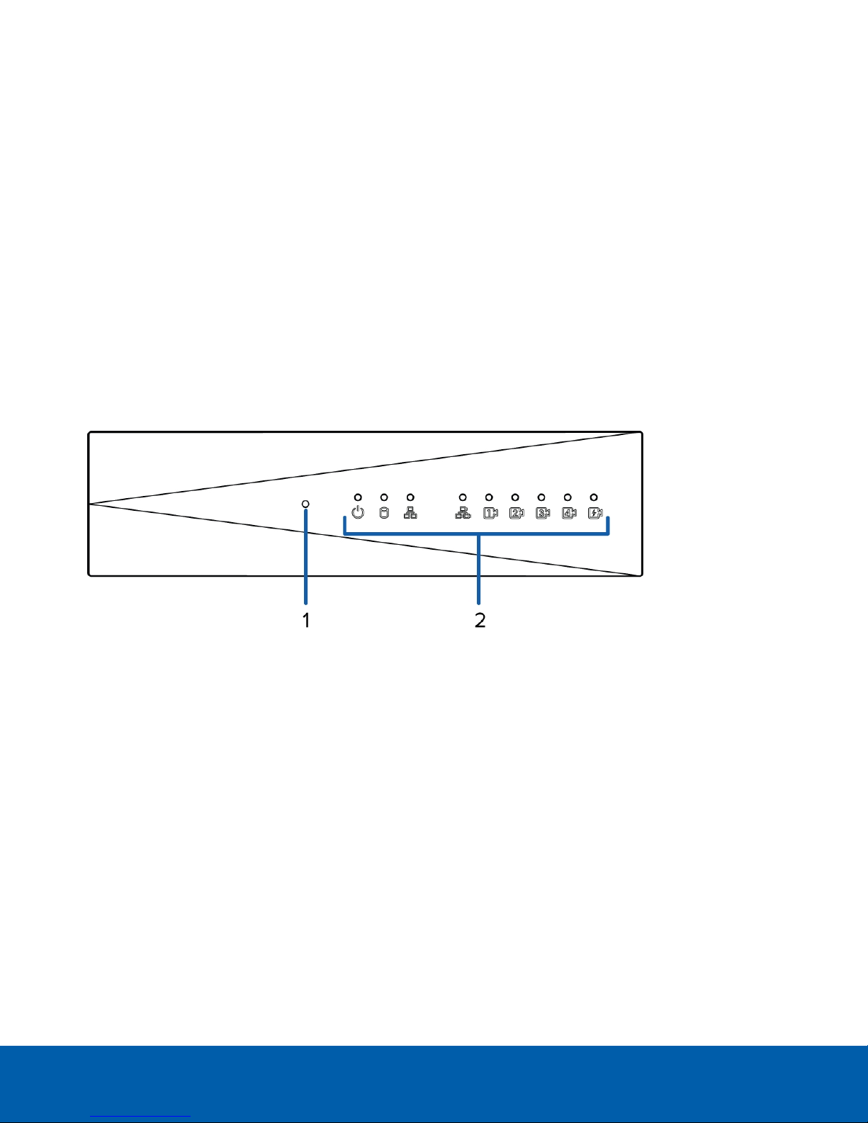
Overview
Front View
1. Reset button
Use this button to physically restart the appliance or perform a factory reset.
2. Status LED
Provides information about daily operations. For more information, see LEDIndicators on page24.
Introduction 1
Page 6
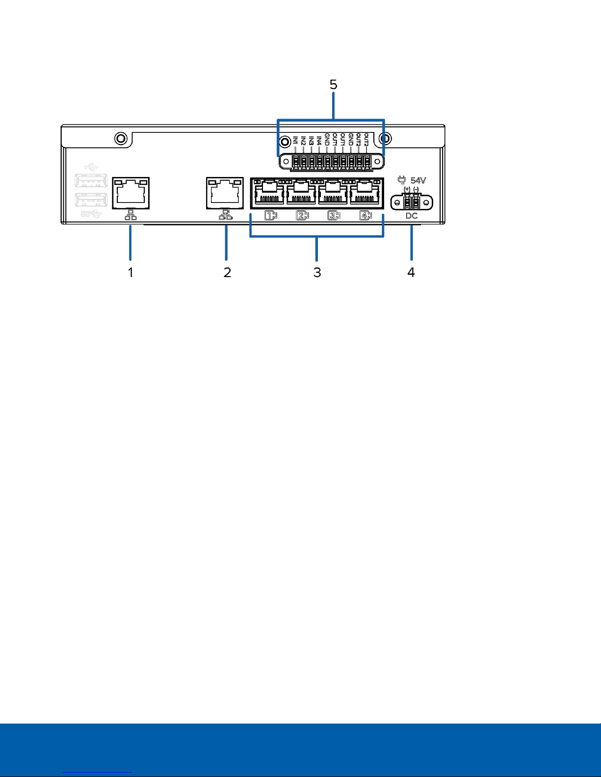
Rear View
1. Corporate network uplink port
Accepts a 1GbE Ethernet connection to the general network to allow users access to the web interface
and connected camera video.
2. Camera network uplink port
Accepts a 1GbE Ethernet connection to the cameras that are connected to the PoE switch component.
Can be used to link to other PoE switches and cameras.
3. PoE switch component
Connect cameras to the 10/100 speed PoE switch component to power the cameras and record video.
4. Power connector
Accepts power to the appliance.
5.
I/O connector
Provides connections to external input/output devices. For more information, see Connecting to External
Devices on page23.
System Requirements
Camera Frame Rate
The ACC ES Analytics Appliance can provide analytics for non-analytics cameras. For optimal analytics
performance, the source camera should stream a minimum of 10 images per second (ips).
Web Browser
The ACC ES Analytics Appliance administration settings are managed through a web interface.
Rear View 2
Page 7

The web interface can be accessed from any Windows®, Mac or mobile device using any of the following web
browsers:
l Mozilla Firefox® browser version 3.6 or later
l Google Chrome™ browser 8.0 or later
l Microsoft Edge™ browser 25 or later
l Safari® 5.0 or later
l Chrome on Android™ 2.2 or later
l Safari on Apple® iOS 5 or later.
l Windows Internet Explorer® browser version 7.0 or later
NOTE: Your web browser must be configured to accept cookies or the web interface will not function correctly.
Supported Network Configurations
NOTE: Camera Uplink Port does not support dynamically switching DHCP servers.
Network
Connections
Corporate LAN
Uplink only
Camera LAN
Uplink only
Corporate and
Camera
LAN Uplink
Camera Web
Interface
Access
No
Yes
via Camera
LAN Uplink
only
Supported IP Configurations
Corporate LAN
Uplink
Static or DHCP
assigned
Unconnected
(leave as DHCP)
Static, DHCPassigned, DHCPZeroconf
Camera LAN
Uplink
Unconnected
(leave as DHCP)
Static, DHCPassigned, DHCPZeroconf
Static, DHCPassigned, DHCPZeroconf
Notes
Camera LAN Uplink and
connected cameras will use
Zeroconf IP addresses.
Corporate and Camera LAN
Uplinks must be on different
subnets.
Supported Network Configurations 3
Page 8

Hardware Installation
Complete the recommended procedure for installing the device:
1. Connect power and wait for the device to start up.
Do not connect any other cables until instructed in this procedure.
The status LED turns green to indicate that the device is turned on.
2. Connect an Ethernet cable directly from a DHCP enabled port on your configuring laptop to the camera
network port on the device.
3. Open a web browser on the connected laptop and enter this IP address: https://169.254.100.100.
If you cannot reach the IP address, see Troubleshooting — Cannot Reach Default IP Address on the next
page.
4. When you are prompted by the web interface, enter a new password for the administrator username.
The Strength meter measures the complexity of your password: Red is too simple, yellow is reasonably
complex, and green is complex. Complexity measures the difficulty to discover your password, not how
secure your password is. A complex password is recommended.
The page refreshes and you are prompted to log in.
5. Enter administrator as the username and your new password.
The Web Interface launch page is displayed.
6. In the navigation sidebar, expand ACC and click Server to open the ACC Server panel.
7. In the General pane, click the Client Installer Download button to download and install a copy of the
AvigilonControl Center (ACC) Client software to the connected laptop.
8. In the navigation sidebar, click Device to open the Device panel.
9. In the Hostname pane, assign a new hostname for the device.
10. In the navigation sidebar, click Network to open the Network panel.
11. In the Corporate and Camera panes, select how it obtains an IPaddress from the corporate network and
the camera network. For more information, see Network Panel on page20.
12. Connect an Ethernet cable from the device to the corporate network.
13. Disconnect the configuring laptop from the device.
14. If required, mount the device on a wall using the supplied mounting brackets.
CAUTION — The device must be mounted as instructed or any issues that arise will not be
covered by the warranty.
a. Attach the wall mount brackets to the lowest threaded holes on the sides of the device.
b. Position the device with the rear panel facing downwards.
c. Screw the wall mounting brackets to the wall.
Hardware Installation 4
Page 9

15. Connect the cameras to the PoE switch component.
NOTE: Allow the device 1 to 2 minutes to budget power to all connected devices. The front camera
status LEDs initially show that PoE is provided to all connected devices, but the status may change if the
system detects that the total power consumption exceeds the PoE limits.
16. If required, connect other switches and cameras to the camera network.
Now, you can configure the device and cameras for daily operation through the Avigilon Control Center Client
software. For more information, see Configuring the Avigilon Control Center™ Software on page6.
Troubleshooting — Cannot Reach Default IP Address
If the 169.254.100.100 address is not accessible during the hardware installation, it is because the network cable
was connected to the corporate network port rather than the recommended camera port.
You can choose to restore the 169.254.100.100 address by reverting the appliance to its factory default settings.
For more information, see Restoring Factory Default Settings on page25.
Or, you can avoid reverting to the factory default settings by discovering the DHCP assigned IPaddress from the
ACC Client software:
1. Download and install the ACC Client software on to the configuration laptop.
The ACC Client software can be downloaded from the Avigilon website: avigilon.com.
2. Launch the ACC Client software.
3. Log into the site that uses this naming convention: VMA-RPA-4Px-xxxxxxxxxx.AVIGILON.
The default username is administrator, with no password.
NOTE: The username and password for the ACC application is separate from the credentials for the
appliance web interface. To change the password for the ACC application, see Changing the
Administrator Password on page7.
4. Display the server Setup tab.
At the top of the window, the appliance IP address is displayed.
5. Open a web browser and enter the IP address in this format: https://<IP address>.
6. Continue the remaining steps for installing the appliance.
Troubleshooting — Cannot Reach Default IP Address 5
Page 10

Configuring the Avigilon Control Center™ Software
The ACC Client software allows you to view live and recorded video, monitor events, set up alarms, and control
user access to the system.
The ACC Client software is the application that you would use on a daily basis. It is also where most of the
system configurations are made.
This section includes the recommended steps for setting up your ACC system for the first time.
Starting Up and Shutting Down the Avigilon Control Center Client
Software
Starting Up the Client Software
Perform one of the following:
l In the Start menu, select All Programs or All Apps > Avigilon > Avigilon Control Center Client.
l
Double-click or desktop shortcut icon.
l From the AvigilonControl Center Admin Tool, click Launch Control Center Client. For more information,
see the AvigilonControl Center Server User Guide.
When you are prompted, log in to your site. You can only access cameras and video after you log in.
Once the application has started, it will automatically display a list of all the sites that are connected to the same
network. You will be prompted to log in to all sites.
Shutting Down the Client Software
1.
In the top-right corner of the Client software, select > Exit.
2. When the confirmation dialog box appears, click Yes.
Logging Into and Out of a Site
After you start the ACC Client software, you are immediately asked to log in to a site. By default, the ACC ES
Analytics Appliance is automatically added to the system as a server within a site of the same name.
Configuring the Avigilon Control Center™ Software 6
Page 11

Logging In
1. Open the Site Login tab. The Site Login tab is automatically displayed if you are launching the Client
software for the first time.
To manually access the Site Login tab, do one of the following:
l
From the top-right corner of the window, select > Log In….
l
From the top-left corner of the application window, click to open the New Task menu, then
click .
2. On the left side of the Site Login tab, select one or more sites.
If the site you want to log into is not shown, click Find Site… to discover the site.
3. Enter your username and password for the selected sites.
4. Click Log In.
You are logged into the selected sites.
If you want to be notified when new or disconnected sites come online, select the Notify me when additional
sites become available check box.
If you want to see the login page each time you launch the Client software, select the Show this tab on startup
check box. If you prefer not to login each time, you can disable this option and configure automatic login from
the Client Settings dialog box.
Logging Out
You can log out of one or all sites at any time.
To... Do this...
Log out of one or select sites l In the System Explorer, select one or more sites then right-click and
select Log Out.
Log out of all sites
1.
In the top-right corner of the Client, select > Log Out.
2. In the confirmation dialog box, click Yes.
Changing the Administrator Password
After you log in to the ACC software for the first time, it is recommended that you change the default
administrator password.
Logging In 7
Page 12

1. After you login, the Change Password dialog is displayed.
2. Enter a new password and then confirm the new password.
The password must meet the minimum strength requirements.
l
— password meets the strength requirements.
l
— password does not meet the strength requirements, enter a new password.
The password strength is defined by how easy it is for an unauthorized user to guess. If your password
does not meet the strength requirements, try entering a series of words that is easy for you to remember
but difficult for others to guess.
3. Click OK.
Tip: If you forget the default administrator password, resetting the password requires restoring the factory
default settings on every server in the site. To avoid this issue, it is highly recommended that you create at least
one other administrator level user as a backup.
Connecting Cameras to the Avigilon Control Center Software
After all the cameras in your system have been physically connected to the ACC ES Analytics Appliance, you
need to connect the cameras to the ACC software so that video can be recorded and indexed for search.
1.
In the site Setup tab, click .
The Connect/Disconnect Devices… tab is displayed.
2. In the Discovered Devices area, select one or more devices then click Connect….
Tip: You can also drag the device to a server on the Connected Devices list.
3. In the Connect Device dialog box, select the server you want the device to connect to.
NOTE: If you are connecting multiple devices, all the cameras must use the same connection settings.
4. If you are connecting a third-party device, you may choose to connect the device by its native driver. In
the Device Type: drop-down list, select the device's brand name. If there is only one option in the dropdown list, the system only supports one type of driver from the device.
5. In the Connection Type: drop-down list, select Primary. The device will automatically connect to this
server if they are in the same network.
If you are creating a failover connection, select Secondary or Tertiary.
6. In the License Priority: drop-down list, select the appropriate license priority. The highest priority is 1 and
the lowest priority is 5.
NOTE: This option is only available if you are connecting to a Secondary or Tertiary server.
ConnectingCameras tothe Avigilon Control Center Software 8
Page 13

The License Priority: setting decides the order that devices are connected to the server. The server will
try to connect cameras with a higher priority before cameras with lower priority. If the server does not
have enough camera channel licenses, low priority devices may not be connected. A camera channel
license is only used when the device actually connects to the server.
7. If the camera supports a secure connection, the Device Control: drop-down list is displayed. Select one
of the following options:
NOTE: The setting may not be displayed if the camera only supports one of the options.
l Secure — The system will protect and secure the camera's configuration and login details. This
option is selected by default.
l Unsecure — The camera's configuration and login details will not be secured and may be
accessible to users with unauthorized access.
Cameras with a secure connection are identified with the icon in the Status column.
8.
If it is not displayed, click to display the Site View Editor and choose where the device appears in the
System Explorer.
l
In the site directory, drag devices up and down the right pane to set where it is displayed.
l
If your site includes folders, select a location for the device in the left pane. The right pane
updates to show what is stored in that directory.
l If you are connecting multiple devices at the same time, the selected devices must be assigned to
the same location.
Tip: If the site you want is not listed, you may need to connect the device to a different server. Make sure
the selected server is connected to the site you want.
9. Click OK.
10. If the device is password protected, the Device Authentication dialog box appears. Enter the device's
username and password, then click OK.
Setting the Recording Schedule
Once all the cameras have been connected, you can set when you want each camera to record video.
By default, all connected cameras are set to record when events are detected by the system. You can skip this
procedure if you prefer to keep the default settings.
Before you can assign a recording schedule, you must create a template. The template allows you to assign the
same schedule to multiple cameras.
Creating a Recording Template
The events that can be selected for the template depend on the licensed features in your system.
NOTE: Be aware that the system recording schedules use the same timezone as the appliance. For more
information about setting the time, see Device Panel on page18.
Setting the RecordingSchedule 9
Page 14

1.
In the server Setup tab, click . The Recording Schedule dialog box is displayed.
2. Click Add Template below the Templates: list.
3. Enter a name for the New Template.
4. Click the Set Area button, then click or drag the cursor across the Recording Mode: timeline to set the
types of events that the cameras will record throughout the day. Individual rectangles on the Recording
Mode: timeline are colored when they have been selected.
The Recording Mode: options include:
l Continuous — record video constantly.
l Motion — only record video when motion is detected.
l Digital Inputs — only record video when a digital input is activated.
l Alarms — only record video when an alarm is activated.
5. To disable recording in parts of the template, click the Clear Area button, then click or drag the cursor
across the timeline to remove the set recording areas.
6. If cameras are not recording in Continuous mode all day, you can set cameras to record reference
images between events in the recording schedule.
l Select the Record a reference image every: check box, then set the time between each reference
image.
Setting Up a Weekly Recording Schedule
You can set up a weekly recording schedule by applying templates to cameras for each day of the week.
1.
In the server Setup tab, click . The Recording Schedule dialog box is displayed.
2. Select a template from the Templates: list.
3. In the Default Week area, click the days of the week this template applies to for each camera.
Figure 1: The Recording Schedule dialog box: Default Week
4. Click OK.
Setting Data Aging
Data aging defines how long recorded video is stored and the quality of the video as it ages over time. In the
ACC software, the recorded image rate is slowly reduced so that recorded video can be viewed over a longer
period of time while still making room for new recordings. You can adjust how long the full image rate video is
kept, so that you have the best quality video when you need it.
Setting Up a Weekly Recording Schedule 10
Page 15

The amount of data aging that is available depends on the camera you have connected to your system:
l For JPEG2000 or JPEG compression cameras, data aging is available at three rates:
l High Bandwidth keeps recordings at their original quality.
l Half Image Rate discards half of the recorded data to make room for new recordings.
l Quarter Image Rate keeps 1/4 of the original recorded data so that you can still see older video.
l For H.264 cameras that support data aging, data aging is available at two rates:
l High Bandwidth keeps the original high quality video and the secondary stream of low resolution
video.
l Low Bandwidth only keeps the secondary stream of low resolution video.
NOTE: The data aging can only occur when the secondary stream is enabled.
l For H.264 cameras that do not support data aging, only the High Bandwidth video is kept.
By default, the system is set to keep recorded video for the maximum amount of time based on the available
storage.
At the bottom of the Recording and Bandwidth dialog is the following statement:
Total record time estimate is based on constant recording
The retention time is determined by the Max. Record Time setting and the average camera data rate. Since the
system can only provide an estimate of the data rate for the full retention period, the actual retention time may
exceed the Max. Record Time setting by 5 minutes.
NOTE: The time shown in the Total Record Time column is an estimate only.
1.
In the server Setup tab, click .
The Recording and Bandwidth dialog box is displayed.
The Data Aging column shows an estimate of the recording time that is available at each image rate,
given the amount of space on the recording device.
2. In the Data Aging column, move the sliders to adjust the amount of time video is stored at each image
rate.
l To change the data aging settings for all linked cameras, move the slider for one linked camera
and all linked cameras will be updated.
l To change the data aging setting for one camera, break the camera's link to other cameras by
clicking the icon to the left of its name, then make your changes.
3. In the Max. Record Time column, manually enter a maximum record time or select one of the options from
the drop-down list for each camera.
NOTE: If the time estimated in the Total Record Time column is significantly shorter than what is set in the
Max. Record Time column, the camera's actual recording time will be closer to the Total Record Time
estimate.
4. Click OK.
Setting Data Aging 11
Page 16

Enabling Server Analytics
You can enable the system to detect classified objects using self-learning video analytics on any non-analytics
camera connected to the appliance.
Be aware that there is a limit to the system's analytic capacity. Refer to the Total Analytic Load bar to avoid
exceeding the system's analytic capacity.
NOTE: The Avigilon ACC ES Analytics Appliance does not currently support unusual motion detection.
1.
In the server Setup tab, click .
2. In the following dialog box, a list of connected cameras are displayed.
Only cameras without video analytics capabilities are displayed.
If you do not have access rights for a camera, it will not be shown in this list.
3. To enable video analytics, select the check box beside the connected camera.
The Total Analytic Load bar displays the appliance's video analytics capacity. The percentage is based
on the enabled camera's current Compression and Image Rate settings.
4. Click OK.
Your settings are now saved.
Adding Users and Groups
If there will be other people using the system, you may want to add them as separate users rather than giving
them access through the default administrator account.
Before you can add individual users, you will need to add permission groups that define what users have access
to. By default, the system has the following groups:
l Administrators — has access to everything in the system.
l Power Users — has access to most features in the system except for the ability to import and export
settings.
l Restricted Users — has access to live video only and can control audio and digital outputs.
l Standard Users — has access to live and recorded video, but cannot make any Setup changes.
It is highly recommended that the Administrators group includes at least two users. In the event one
administrator user forgets the default administrator password, the second administrator user can be used to
reset the password. If you do not have a second administrator user, you may need to completely reset the
system.
Enabling Server Analytics 12
Page 17

Adding Groups
1.
In the site Setup tab, click .
2. In the following dialog box, select the Groups tab and click Add Group.
3. In the pop-up dialog box, select an existing group to use as a template for your new group, then click OK.
4. In the Edit Group dialog box, complete the following:
a. Give the new group a name.
b. Select a rank for the group from the Rank: drop-down list. To edit or view the entire Corporate
Hierarchy, click .
c. Move the Min Password Strength: slider to define how strong the password used by each user in
the group must be.
The password strength is defined by an algorithm that anticipates how easy a password is to
guess. There is no defined character minimum, but the stronger the setting, the harder it should be
for an unauthorized user to crack the password.
Tip: If users are expected to change their passwords frequently, you may want to select a weaker
setting to ensure users do not have difficulty choosing new passwords.
d. Select the required Group Privileges: and Access Rights: for the group. Clear the check box of any
feature or device that you do not want the group to have access to.
5. Click Edit Groups to enable the Dual Authorization feature.
When you enable Dual Authorization, users in this group cannot review recorded video without
permission from a user in the authorizing group.
a. In the following dialog box, select the groups that can grant authorization to users in this group.
b. To disable the feature, click the toggle at the top of the dialog box.
c. Click OK.
6. Select the Members tab to add users to the group.
If a user is added to the group through the Add/Edit User dialog box, the user is automatically added to
the group's Members list.
a.
Click .
b. Select the users that should be part of this new group. Only users that have been added to the site
are displayed.
Tip: Enter the name of a user in the Search… field to locate specific users.
c. Click Add. The users are added to the Members list.
7. Click OK to save the new group.
Adding Groups 13
Page 18

Adding Users
1.
In the site Setup tab, click .
2. In the Users tab, click Add User.
3. When the Add/Edit User dialog box appears, complete the User Information area.
4. If you don’t want this user to be active yet, select the Disable user check box. Disabled users are in the
system but cannot access the site.
5. In the Login Timeout area, select the Enable login timeout check box to set the maximum amount of time
the Avigilon Control Center Client software can be idle before the user is automatically logged out of the
application.
6. Select the Member Of tab to assign the user to a group.
a. Select the check box beside each access group the user belongs to.
The other columns display the permissions that are included in the selected groups.
b. Return to the General tab.
7. In the Password area, complete the following fields:
l Password: — enter a password for the user.
l Confirm Password: — re-enter the password.
l Strength: — indicates the strength of the password. The strength is defined by the group the user
is assigned to. If the user is a member of more than one group, the user must meet the strongest
password requirement.
The password must meet the minimum strength requirements.
l
— password meets the strength requirements.
l
— password does not meet the strength requirements, enter a new password.
The password strength is defined by how easy it is for an unauthorized user to guess. If your
password does not meet the strength requirements, try entering a series of words that is easy for
you to remember but difficult for others to guess.
l Require password change on next login — select this check box if the user must replace the
password after the first login.
l Password Expiry (Days): — specify the number of days before the password must be changed.
l Password never expires — select thischeck box if the password never needs to be changed.
8. Click OK. The user is added to the site.
Repeat this procedure to add all the users that are required.
Advanced Settings
The following list include some advanced settings that you can use to further customize your system. See the
application Help files for details about how to configure these settings.
Adding Users 14
Page 19

l Adjust camera settings
l If camera video looks slightly blurry or unclear, you can adjust the camera's Image and Display
settings.
l If you want the camera to record at a different image rate, you can adjust the camera's
Compression and Image Rate settings.
NOTE: For optimal analytics performance, the source camera should stream a minimum of 10
images per second (ips).
l To reduce the amount of ambient motion detection for a specific camera, you can adjust the
Motion Detection settings.
l To maintain the privacy of certain areas, you can set Privacy Zones in the camera's field of view so
that private spaces are never recorded.
l Classified object detection
l Available to cameras that have server-side analytics enabled, and available to other Avigilon
video analytics cameras.
l Use the Analytic Events dialog box to configure classified object motion detection. Once
configured, you can receive events, trigger alarms, define rules, and record video when specific
object motion requires your attention.
l Alarms
l Use the Alarms dialog box to create and manage alarms. Once an alarm has been created, you can
monitor alarm events in the Alarms tab and in the Avigilon Control Center Mobile App.
l Configure digital inputs and outputs
l The digital I/O connector on the appliance can be configured as an independent digital I/O device.
l Use the Digital Inputs and Outputs dialog box to configure the appliance's I/O settings. Once
configured, you can use the digital inputs and outputs in alarms and other system actions.
l Email notifications
l You can set up an SMTP email server to send you messages when system events occur.
l Setup the Gateway
l The ACC Gateway software allows you to access video from a remote web browser or mobile
device. If the Gateway software is not set up, you cannot access video outside of your local
network.
l Install the ACC Mobile app on your mobile device so that you can remotely monitor live and
recorded video.
Advanced Settings 15
Page 20

Configuring the Appliance
The ACC ES Analytics Appliance can be configured through a web interface that is accessible from any browser
on the network. The web interface allows you to configure the appliance server settings like the AvigilonControl
Center Admin Tool.
The web interface allows you to configure the network settings, set how the system keeps time, and allows you
to remotely restart or upgrade the system.
Accessing the Web Interface
During the installation process, you connected a laptop directly to the device and used a special IP address to
access the web interface. After the device has been set up and is connected to the corporate network, you can
access the web interface following these steps:
1. On a computer with network access to the device enter the IP address of the device into a web browser:
https://<Device IP address >/
For example: https://192.168.1.40/
Tip: If you forgot the IPaddress that was configured during the installation process, the device IP address
is listed in the ACC Client software, in the server Setup tab.
2. When you are prompted, enter the web interface username and password.
The username is always administrator. Use the password you configured when you logged in to the
device for the first time. For more information, see Hardware Installation on page4.
Web Interface Launch Page
The Web Interface launch page consists of a Dashboard navigation bar and five panes displaying status
information:
l ACC Server: Displays Running when the ACC Server software is operating; otherwise it displays Stopped.
The panel provides technical information about the device:site name, server name, server ID,server
version, software version, the number of available camera channels, and the maximum number of ACC
client instances allowed.
l System: Displays Ready when the device is fully operational, and Rebooting then Initializing when the
device is restarting. The panel provides technical information about your device:product name, part
number, serial number, and firmware version.
l Storage: Displays the storage capacity of the device and the status of the storage disks.
l
Network—Displays information about the two uplink ports on the device. Click to open the Network
Panel.
l PoE—Displays status information about each PoE port. Icons in the panel let you quickly see how many
ports are in use, their status, speed and whether the link is up or down. Click to open the Device Panel.
Configuring the Appliance 16
Page 21

Use the menu options under Services and System in the Dashboard navigation bar to access all the other Web
Interface panels.
l Services: Expand ACC in the left sidebar to navigate to the Server page to control the ACC Server on the
device and the Logs page to view ACC Server service logs.
l System: Access the five options to configure the device and view its status.
ACC Server Panel
On the Server panel use the:
l General pane:
To... Do this...
Shut down the ACC Server software before you shut
down the device.
Start up the ACC Server software after the ACC Server
software has shut down.
Format the disk drives. Click Reinitialize to delete all configuration and
Download the AvigilonControl Center Client. Click Downloadto start downloading the
l Network Storage Management pane:
Click Stop.
Click Start.
recorded video data.
AvigilonControl Center Client.
To allow users to archive video from this device using the ACC Client software:
1. Click Enabled.
2. From the Protocol drop down list, select one of the following:
l CIFS — Common internet file system. The network path is typically in this format:
//<hostname or IP> / <path>
l NFS — Network file system. The network path is typically in this format: <hostname or IP> :
<path>
3. In the Network Path field, enter the path to the preferred video archiving location.
4. If the network location requires authentication, select the Authentication check box then enter the
credentials in the Username and Password fields.
5. Click Apply.
l Service and RTP Ports panes
To change the UDPand TCP ports used to communicate with the ACC Server software:
l In the Service Ports pane, enter the Base value to use for the HTTP, HTTPS, and UDPports and
click Apply. The list of ports is updated.
l In the RTP Ports pane, enter the Base value to use for the UDPports and click Apply. The range of
ports available for RTP is updated.
Important: These changes can only take effect after the system restarts. When you are prompted, allow
the system to restart.
ACC Server Panel 17
Page 22

ACC Logs Panel
Use the ACC Logs page to view ACC Server service logs. The logs are typically requested by Avigilon
Technical Support to help resolve an issue.
By default, the page displays 100 warning messages from the ACC Server Logs.
You can filter the logs to display the information that you need:
1. In the drop down list, select the type of application log that you need. The options are:
o
Exception Logs
o
FCP Logs
o
Server Logs
o
WebEndpoint Logs
2. In the Maximum Logs drop down list, select the number of log messages you want to display each time.
3. Enter text in the Filter field to apply a filter to the log listings.
4. Click the Sync button to display the updated logs.
Device Panel
On the Device panel use the:
l Generalpane to:
l Reboot the device from the web interface. You can monitor the progress of the device as it
reboots from the Web Interface Launch Page on page16.
l Select a Language for the web interface from the drop down list.
l Hostname pane to enter a new Hostname. Click Apply to make the change.
The default hostname is provided in this format:
<Model>-<Serial Number>.AVIGILON
e.g. VMA-RPA-4P2-KSA1234567.AVIGILON
l Password pane to change the administrator password:
NOTE: You cannot change the default administrator username on the web interface, only the password.
1. To change your password, confirm your identity by entering your current password in the Old
Password field.
2. Enter the new password in the New Password field.
3. Re-enter the new password in the Confirm Password: field.
4. Click Apply to save the new password.
CAUTION — You will lose recorded video and configuration data if you forget your password. To reset
the administrator password, you must reset the device to the factory default settings. This will also format
the hard drives and delete the configuration data and recorded video. For more information on
performing a factory restore, see Restoring Factory Default Settings on page25.
ACC Logs Panel 18
Page 23

l Use the Time pane to customize how the device keeps time:
l Select the Time Zone check box then select the local time zone.
l Select whether you want to keep synchronized time through a Network Time Protocol (NTP)
server (recommended), in the NTP field. Select:
l DHCP to automatically use an existing NTP server in the network.
l Manual to enter the address of the NTP server in the Servers list. Controls to add and
delete addresses from the list are activated.
l Off if you do not use an NTP server.
NOTE: If you have multiple ACC systems running on the network, make sure they all synchronize
with the same NTP server.
Click Apply to save the time settings.
l Use the Upgrade Firmware pane to install the latest version of the firmware on your device, or to reinstall
the firmware if it becomes corrupted.
Choosing to upgrade corrupted firmware helps you avoid reverting to the factory default settings. When
you revert to the factory default settings, all of the configured settings are lost and all recorded video is
deleted.
Before you can upgrade or reinstall the firmware, download the latest version of the firmware (fp) file
from the Avigilon website (avigilon.com) and save it to a location accessible to the Web UIInterface for
the device.
To upgrade the firmware, use one of these methods:
l Drag-and-Drop
1. Use Windows Explorer to navigate to the location of the downloaded firmware file.
2. Click on the file in the Explorer window and drag it over the Drop '.fp' file here or
click to upload area.
l Click to upload
1. Click in the Drop '.fp' file here or click to upload. The Windows Open dialog box is
displayed.
2. Use Windows Explorer to navigate to the location of the downloaded firmware file.
3. Click on the file in the Open dialog box and click Open.
The upgrade starts as soon as the file is uploaded to the device. Allow the system to reboot when the
following message is displayed:
rRebooting
A progress bar displays the upload status.
As the system upgrades, a blue progress message is displayed at the bottom of the screen. When the
upgrade is complete, the message turns green. Refresh the page periodically to receive the latest status
update.
After the reboot is complete, you can return to normal operations.
Device Panel 19
Page 24

If you are only able to access the web interface and none of the other system features, run the same
firmware upgrade again or revert to the factory default settings.
NOTE: If an error occurs during the upgrade process or if the firmware becomes corrupted, the system
may revert to the factory default settings as the system reboots.
Network Panel
On the Network panel, you can change network connections of the device. Two network connections are
supported: one for a corporate network and one for a camera network.
The corporate network is the network that typically provides users with access to the device. Users who monitor
video through the ACC Client software would connect to the device through this network.
The camera network is a closed network that typically only contains cameras. This reduces the amount of
interference with video recording.
For more information about the network connections, see Supported Network Configurations on page26.
You can perform any of the following:
To... Do this...
Set how the device
obtains an IP address
for each network.
NOTE: The Corporate
Network and the
Camera Network must
be on different
subnets.
In the Corporate and Camera panes, toggle Automatic on to discover connected
networks automatically (the default setting), or off to manually specify the
connections. Enter the appropriate values in the following fields if you are manually
entering the connection settings:
l
IP Address
l
Subnet Mask
l
Default Gateway
Click Apply to save your changes.
Set how the device
obtains a named
address from a DNS
server.
In the DNS pane, toggle Automatic on to discover connected DNSservers
automatically (the default setting), or off to manually specify the DNSserver. Enter the
appropriate values for Preferred Server, Alternate Server 1, and Alternate Server 2 if
you are manually specifying DNS servers for addressing the device.
Budgeting PoE Power
The PoE switch component on a 4-port device can output a total of 64W of power to the connected devices,
and on an 8-port device can output a total of 128 W. Each PoE port is capable of outputting 16W to standard
PoE devices, and 30W to PoE+ devices. This typically means that a 4-port device can support up to 4 standard
PoE devices or up to 2 PoE+ devices.
Advanced users can manually adjust the PoE power budget for each port to consistently accommodate the
cameras needed.
If you choose to manually adjust the PoE budget at each port, be aware that you must also account for potential
power loss in the cable. Unless the amount of power loss in the cable is known, use the following estimates:
Network Panel 20
Page 25

l If the device uses less than or equal to (<=) 16W — expect 2.5W of power loss.
l If the device uses more than (>) 16W — expect 4.5W of power loss.
To calculate the recommended power budget for each port, use the following equation:
Power budget = <Camera power consumption> + <Expected cable power loss>
Example: Connect the following 4 cameras to a 4-port device:
2 x HD dome cameras ( 9W +2.5 W) x 2 = 23W
1 x HD PTZ camera 25.5W + 4.5W = 30W
1 x HD micro dome 4W + 2.5W = 6.5W
Total
= 59.5W
The total power consumption of the 4 cameras is within the PoE switch component limits.
NOTE: If you miscalculate the required power for a PoE port, the connected camera may be shut down if total
power output exceeds 64W.
Assigning a PoE Power Budget
On the PoE page, you can see how much power is available to, and being used by, connected devices. The
default setting for all ports is Auto. This setting automatically detects and budgets the amount of power required
by the device connected to the port. For each port you can adjust this setting manually, or turn off power output
completely. If you want to manually adjust the power output of the ports you must calculate a PoE power
budget, see Budgeting PoE Power on the previous page.
Click PoE from the Dashboard navigation bar to open the PoE page.
The Budget bar indicates the total amount of power budgeted for all devices connected to the PoE ports. The
Consumption bar indicates the actual amount of power currently used by all the connected devices.
Use the Powered bar for each port to configure a PoE power budget for each port:
l Click Off to disable power output to the port. When power to a port is disabled, the port no longer outputs
power but can act as a standard network connection for any device.
Tip: You can also use this feature to remotely power cycle the camera. After you set the Powered setting
to Off, wait for the camera to power off then change the Powered setting to Auto or Manual .
l Click Auto to automatically output power to the connected device depending on its mode of operation.
l Click Manual to enter a power budget value in watts. Make sure the budget includes potential power loss
at the cable.
Tip: Devices that support both PoE and PoE+ (802.3at) modes of operation can be forced into non-PoE+
mode (802.3af) by using a manual 16W budget.
Settings are not implemented until you click Apply.
After you click Apply, allow the system to reboot when the following message is displayed:
Applying changes may power-cycle PoE-powered devices.
Assigninga PoEPower Budget 21
Page 26

The Web Interface automatically refreshes the screen and displays the updated settings after the new power
settings are applied.
PoE Status
Tip: If a camera is disconnected then reconnected to the device, you may need to refresh this page to view the
latest status and budget values.
The PoE panel displays a status for each port in the Status column. Statuses include the following:
l Disconnected: there is no Ethernet cable connected to the port.
l ???: a PoE device is connected to the port and is operating normally.
l Unpowered: a device is using the port for a network connection only.
l Overloaded: a PoE device is connected to the port but is not receiving power. This status typically occurs
when the port is overcurrent, device is requesting more power than budgeted, etc.
l High powered: ??
l Low current:??
System Logs Panel
Use the System Logs page to view the device logs. The logs are typically requested by Avigilon Technical
Support to help resolve an issue.
By default, the page displays 100 warning messages from the Logs.
You can filter the logs to display the information that you need:
1. In the drop down list, select the type of application log that you need. The options are:
o
System Logs
o
Boot Logs
o
Web Server Logs
2. In the Maximum Logs drop down list, select the number of log messages you want to display each time.
3. Enter text in the Filter field to apply a filter to the log listings.
4. Use Filter to apply filter to the logs.
5. Click the Sync button to display the updated logs.
PoE Status 22
Page 27

Connecting to External Devices
External devices are connected to the appliance through the I/O terminal. The pinout for the I/O terminal is
shown in the following diagram:
1. OUT 2 (Relay Output) — Form-A dry contact outputs. When active, terminals are connected. Terminals are
open when inactive.
Maximum load is 30V, 2A or 200V, 250mA.
2. OUT 2
3. Ground (GND)
4. OUT 1 (Relay Output) — Form-A dry contact outputs. When active, terminals are connected. Terminals are
open when inactive.
Maximum load is 30V, 2A or 200V, 250mA.
5. OUT1
6. GND
7. IN 4 (Alarm In)— Active-Low inputs. To activate, connect the Input to the Ground pin (GND). To deactivate,
leave disconnected or apply between 3 – 15V.
8. IN 3
9. IN 2
10. IN 1
Connectingto External Devices 23
Page 28

LEDIndicators
The following list describes what the LEDs on the ACC ES Analytics Appliance indicate.
Front Panel LEDs
Icons LED Status Description
Green Device is powered and running.
Orange Device is restarting.
Orange - blinking Factory restore button pressed.
Green Hard disk drive is connected.
Red Hard disk drive connection has an error.
Green Camera is using the switch for a network connection
and Power over Ethernet (PoE) power.
Orange Camera is only using the switch for a network
connection.
Orange - slow
blinking
Alternating Green Orange
Orange GigE network link is present.
Green 10/100 network link is present.
Orange Switch component has reached its PoE output
Port off due to failure.
Port off due to system over power budget.
capability.
Back Panel LEDs
Icons LED Status Description
Green Network activity is present.
Orange On for GigE speed. Off for 10/100 speed.
Green Network activity is present.
LEDIndicators 24
Orange On for 100M speed. Off for 10M speed.
Page 29

Using the Reset Button
The reset button is located at the front of the appliance and is the small unlabeled circle to the left of the System
Status LED. For more information, see Front View on page1
The reset button provides two functions:
l Restart the system — If the appliance encounters a system error, you can force it to restart.
l Restore the factory default settings — If the ACC software no longer functions as expected, you can reset
the appliance to its factory default settings. All configuration settings and recorded data will be deleted.
NOTE: When you use the reset button, the appliance must be powered.
Restarting the System
If the appliance encounters a system error and you are unable to access the web interface, you can try to
resolve the issue by restarting the system from the physical appliance.
l Using a straightened paperclip or similar tool, gently press and release the reset button.
CAUTION — Do not apply excessive force. Inserting the tool too far will damage the
appliance and void the warranty.
Important: Do not hold down the reset button for too long or you will revert to the factory default settings.
Restoring Factory Default Settings
If the ACC Server software no longer functions as expected or if you've forgotten your administrator password,
you can reset the appliance to its factory default settings.
NOTE: Restoring to the factory default settings will delete all configuration settings and recorded video.
1. Using a straightened paperclip or similar tool, gently press and hold the reset button.
CAUTION — Do not apply excessive force. Inserting the tool too far will damage the
appliance and void the warranty.
2.
Do not release the button until the LED is orange and starts to blink.
Usingthe Reset Button 25
Page 30

Supported Network Configurations
NOTE: Camera Uplink Port does not support dynamically switching DHCP servers.
Network
Connections
Corporate LAN
Uplink only
Camera LAN
Uplink only
Corporate and
Camera
LAN Uplink
Camera Web
Interface
Access
No
Yes
via Camera
LAN Uplink
only
Supported IP Configurations
Corporate LAN
Uplink
Static or DHCP
assigned
Unconnected
(leave as DHCP)
Static, DHCPassigned, DHCPZeroconf
Camera LAN
Uplink
Unconnected
(leave as DHCP)
Static, DHCPassigned, DHCPZeroconf
Static, DHCPassigned, DHCPZeroconf
Notes
Camera LAN Uplink and
connected cameras will use
Zeroconf IP addresses.
Corporate and Camera LAN
Uplinks must be on different
subnets.
Supported Network Configurations 26
Page 31

Troubleshooting — Cannot Reach Default IP
Address
If the 169.254.100.100 address is not accessible during the hardware installation, it is because the network cable
was connected to the corporate network port rather than the recommended camera port.
You can choose to restore the 169.254.100.100 address by reverting the appliance to its factory default settings.
For more information, see Restoring Factory Default Settings on page25.
Or, you can avoid reverting to the factory default settings by discovering the DHCP assigned IPaddress from the
ACC Client software:
1. Download and install the ACC Client software on to the configuration laptop.
The ACC Client software can be downloaded from the Avigilon website: avigilon.com.
2. Launch the ACC Client software.
3. Log into the site that uses this naming convention: VMA-RPA-4Px-xxxxxxxxxx.AVIGILON.
The default username is administrator, with no password.
NOTE: The username and password for the ACC application is separate from the credentials for the
appliance web interface. To change the password for the ACC application, see Changing the
Administrator Password on page7.
4. Display the server Setup tab.
At the top of the window, the appliance IP address is displayed.
5. Open a web browser and enter the IP address in this format: https://<IP address>.
6. Continue the remaining steps for installing the appliance.
Troubleshooting — Cannot Reach Default IP Address 27
Page 32

Limited Warranty and Technical Support
Avigilon warranty terms for this product are provided at avigilon.com/warranty.
Warranty service and technical support can be obtained by contacting Avigilon Technical Support:
avigilon.com/contact-us/.
Troubleshooting — Cannot Reach Default IP Address 28
 Loading...