

Page 1
User Manual
Avigilon Blue™ Connect Device
VMA-BLU-8P8
Page 2
Important Safety Information
This manual provides installation and operation information and precautions for the use of this device. Incorrect
installation could cause an unexpected fault. Before installing this equipment read this manual carefully. Please
provide this manual to the owner of the equipment for future use.
The Warning symbol indicates the presence of dangerous voltage within and outside the product
enclosure that may constitute a risk of electric shock, serious injury or death to persons if proper
precautions are not followed.
The Caution symbol alerts the user to the presence of hazards that may cause minor or moderate injury
to persons, damage to property or damage to the product itself if proper precautions are not followed.
WARNING — Failure to observe the following instructions may result in severe injury or death.
l Installation must be performed by qualified personnel only and must conform to all local codes.
l Do not open or disassemble the device. There are no user serviceable parts.
l Refer all servicing to qualified personnel. Servicing may be required when the device has been
damaged, has been exposed to moisture, does not operate normally, or has been dropped.
l Only use the power adapter supplied with your system.
CAUTION — Failure to observe the following instructions may result in injury or damage to the
appliance.
l Do not subject cables to excessive stress, heavy loads or pinching.
l Do not operate in dusty areas.
l This device is for indoor use only.
l Do not expose this product to rain or use near water. If this product accidentally gets wet, unplug it
immediately.
l Keep product surfaces clean and dry. To clean the outside case of the device, gently wipe using a lightly
dampened cloth (only use water, do not use solvents).
l Do not install near any heat sources such as radiators or other sources of heat.
l Do not block ventilation openings located on the device enclosure as they are designed to keep the
system cool while running. Install or place this product in an area where there is ample air circulation.
l Do not insert anything into the device ventilation openings.
l The equipment is not suitable for use in locations where children are likely to be present.
l Use only accessories recommended by Avigilon.
l Keep these safety instructions.
ii
Page 3

Regulatory Notices
This device complies with Part 15 of the FCC Rules. Operation is subject to the following two conditions: (1)this
device may not cause harmful interference, and (2) this device must accept any interference received, including
interference that may cause undesired operation.
NOTE: This equipment has been tested and found to comply with the limits for a Class B digital device, pursuant
to part 15 of the FCC Rules. These limits are designed to provide reasonable protection against harmful
interference in a residential installation. This equipment generates, uses and can radiate radio frequency energy
and, if not installed and used in accordance with the instructions, may cause harmful interference to radio
communications. However, there is no guarantee that interference will not occur in a particular installation. If this
equipment does cause harmful interference to radio or television reception, which can be determined by
turning the equipment off and on, the user is encouraged to try to correct the interference by one or more of the
following measures:
l Reorient or relocate the receiving antenna.
l Increase the separation between the equipment and receiver.
l Connect the equipment into an outlet on a circuit different from that to which the receiver is connected.
l Consult the dealer or an experienced radio/TV technician for help.
This Class B digital apparatus complies with Canadian ICES-003 (B)/NMB-3(B)
CAUTION — Risk of explosion if battery is replaced by an incorrect type. Dispose of used batteries according to
the instructions.
The unit and all interconnected equipment must be installed indoors within the same building, including all POEpowered network connections as described by Environment A of the IEEE 802.3af standard.
Changes or modifications made to this equipment not expressly approved by Avigilon Corporation or parties
authorized by Avigilon Corporation could void the could void the warranty and affect the user’s ability to
operate this equipment.
Disposal and Recycling Information
When this product has reached the end of its useful life, please dispose of it according to your local
environmental laws and guidelines.
Risk of fire, explosion, and burns. Do not disassemble, crush, heat above 100 °C (212 °F), or incinerate.
European Union:
iii
Page 4

This symbol means that according to local laws and regulations your product should be disposed of separately
from household waste. When this product reaches its end of life, take it to a collection point designated by local
authorities. Some collection points accept products for free. The separate collection and recycling of your
product at the time of disposal will help conserve natural resources and ensure that it is recycled in a manner
that protects human health and the environment.
Disclaimers
©2018,Avigilon Corporation. All rights reserved. AVIGILON, the AVIGILON logo, AVIGILON BLUE, the
AVIGILON BLUE logo, and TRUSTED SECURITY SOLUTIONS are trademarks of Avigilon Corporation. FINDER
and MACINTOSH are registered trademarks of Apple Inc. FIREFOX is a registered trademark of Mozilla
Foundation. WINDOWS is a registered trademark of Microsoft Corporation. ONVIF is a trademark of Onvif, Inc.
Other names or logos mentioned herein may be the trademarks of their respective owners. The absence of the
symbols ™ and ® in proximity to each trademark in this document or at all is not a disclaimer of ownership of the
related trademark. Avigilon Corporation protects its innovations with patents issued in the United States of
America and other jurisdictions worldwide (see avigilon.com/patents). Unless stated explicitly and in writing, no
license is granted with respect to any copyright, industrial design, trademark, patent or other intellectual
property rights of Avigilon Corporation or its licensors.
Each user must accept the Terms and Conditions of Service and the End User License Agreement for Avigilon
Blue as a condition to using the AvigilonBlue cloud platform when they register their account..
The contents of this document and the specifications of the products discussed herein are subject to change
without notice. Avigilon Corporation reserves the right to make any such changes without notice. Neither
Avigilon Corporation nor any of its affiliated companies: (1) guarantees the completeness or accuracy of the
information contained in this document; or (2) is responsible for your use of, or reliance on, the information.
Avigilon Corporation shall not be responsible for any losses or damages (including consequential damages)
caused by reliance on the information presented herein.
Avigilon Corporation
avigilon.com
PDF-VMA-BLU-8P8-A
Revision: 1 - EN
20180312
iv
Page 5

Table of Contents
Introduction 1
Overview 1
Front View 1
Rear View 2
Avigilon Blue Connect Device System Requirements 2
Camera Frame Rate 2
Web Browser 2
Before Installation 3
Dealer Preparation 3
Physical Preparation 3
Hardware Installation 4
Accessing the Avigilon Blue Connect Dashboard 5
Activating the Avigilon Blue Connect Device 6
Activating with an Activation Code 7
Supported Network Configurations 8
Port Configuration 9
Estimating Analytics Load 10
LEDIndicators 12
Front Panel LEDs 12
Back Panel LEDs 12
Using the Reset Button 13
Restarting the System 13
Restoring Factory Default Settings 13
Appendix: Using the Device Web User Interface to Configure the Avigilon Blue Connect Device 14
Accessing the Avigilon Blue Connect Dashboard 14
Dashboard 14
Device 15
Network 15
The Corporate and Camera Panes 15
The DNSPane 16
Assigning a PoE Power Budget 16
Budgeting PoE Power 17
Viewing Service and Device Logs 17
v
Page 6

About 18
vi
Page 7
Introduction
The Avigilon Blue Connect device is the on-premise recording and video analytics device for subscribers of the
Avigilon Blue cloud platform. The Avigilon Blue Connect device includes:
l A network switch to connect and power up to eight IP cameras.
l Built-in server and storage to record and retain recorded video content.
l Local video content storage that can be accessed remotely with the Avigilon Blue web interface.
l Avigilon's video analytics engine to enable connected cameras to become smarter.
This guide is intended as a reference for the person installing the Avigilon Blue Connect device and contains
more technical detail than the in-box installation guide. It fully describes how to install the device and configure
the system after the device has been powered and is connected to the Avigilon Blue cloud platform
subscriber's local area network.
Overview
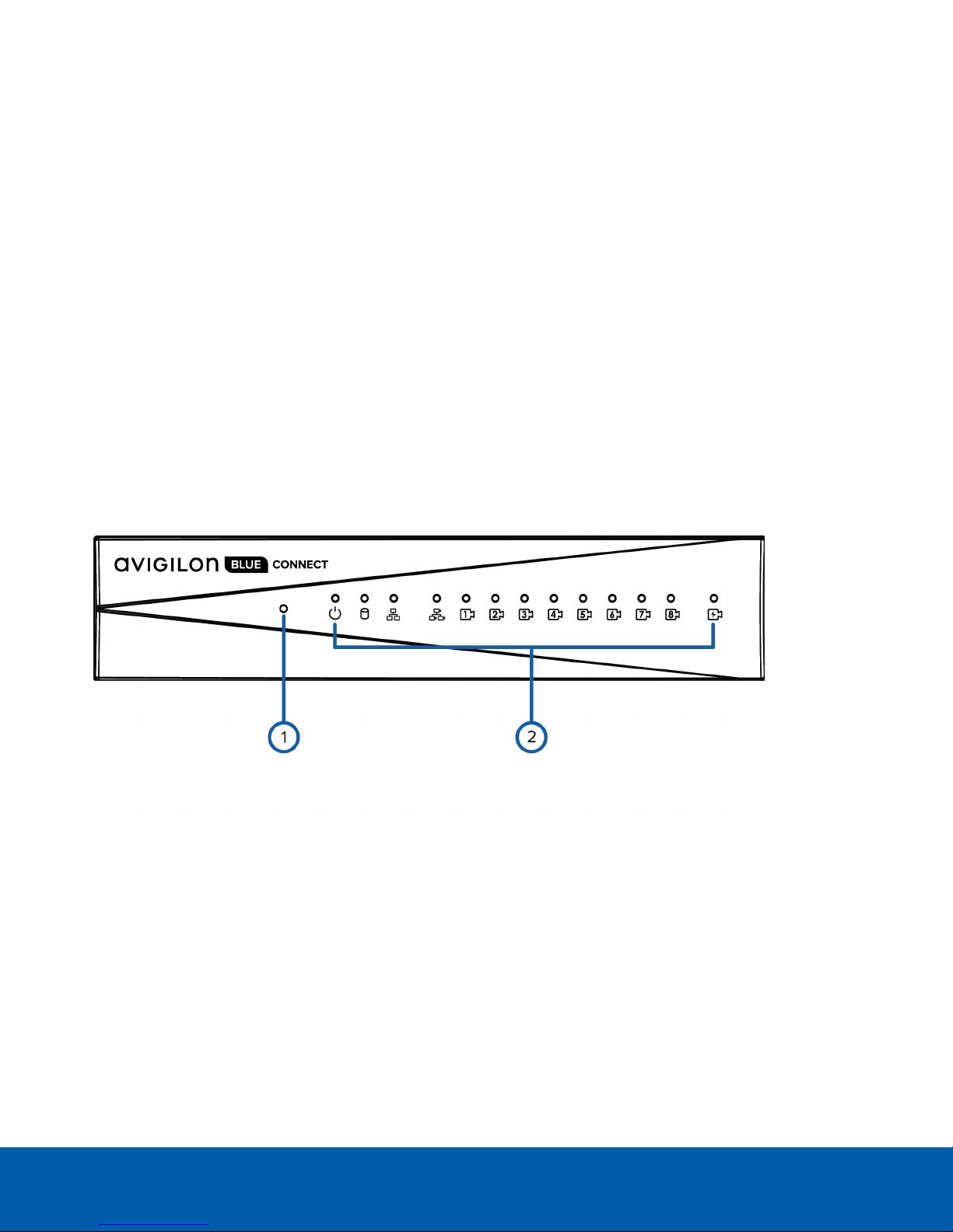
Front View
1. Reset button
Use this button to physically restart the Avigilon Blue Connect device or perform a factory reset.
2. Status LEDs
Provide information about daily operations. For more information, see LEDIndicators on page12.
Introduction 1
Page 8
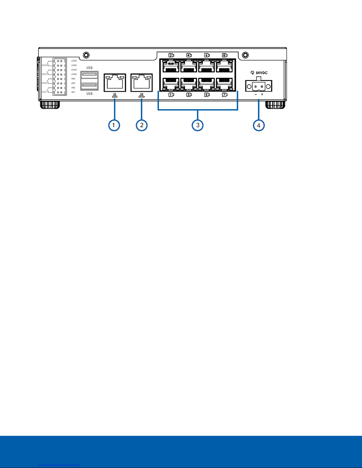
Rear View
1. Corporate network uplink port
1Gb Ethernet connection to provide WANaccess to the Avigilon Blue cloud platform. Allows subscribers
access to the connected camera video, and allows administrator access to the Avigilon Blue Connect
Dashboard.
2. Camera network uplink port
1Gb Ethernet connection to the cameras that are connected to the PoE switch component. Can be used
to link to other PoE switches and cameras.
3. PoE switch component
Connect cameras to the 10/100 speed PoE switch component to power the cameras and record video.
4. Power connector
Connects the Avigilon Blue Connect to the power adapter.
Avigilon Blue Connect Device System Requirements
Camera Frame Rate
The Avigilon Blue Connect device can perform video analytics on video streamed through the system. For
optimal analytics performance, the source camera should stream a minimum of 10 images per second (ips).
Web Browser
The Avigilon Blue cloud platform administrator can use the Avigilon Blue Connect Dashboard to manage the
Avigilon Blue Connect device settings.
The Avigilon Blue Connect Dashboard is a web interface that can be accessed from any Windows® or
Macintosh® computer using any of the following web browsers:
l Mozilla Firefox® browser version 3.6 or later
l Google Chrome™ browser 8.0 or later
NOTE: Your web browser must be configured to accept cookies or the web interface will not function correctly.
Rear View 2
Page 9

Before Installation
The person installing an Avigilon Blue Connect device must confirm that the site plan has been completed and
set up for the Avigilon Blue cloud platform subscriber. There are two aspects to site planning: dealer preparation
and physical preparation.
Dealer Preparation
The dealer must ensure that Avigilon Order Management has completed all the steps required to prepare the
site for the Avigilon Blue cloud platform subscriber within the dealer's organization in the Avigilon Blue cloud
platform. These steps are:
1. Create the subscriber organization.
2. Create and invite site administrators and site users to be in the subscriber organization.
3. Create the site or sites where Avigilon Blue Connect devices will be installed for the subscriber
organization.
This ensures that the site is available to the Avigilon Blue cloud platform subscriber and their Avigilon Blue cloud
platform users.
Physical Preparation
The network on the customer premises must be DHCP-enabled. Computers on the network must be able to
discover other devices on the network. Computers using the Windows OS use UPnP and those using MacOS
use Bonjour to discover network devices. For more information, check the appropriate Help and Support files
for the operating system.
Before Installation 3
Page 10

Hardware Installation
A dealer representative should complete the recommended procedure for installing the Avigilon Blue Connect
device:
1. Note the serial number on the label on the underside of the device.
2. If required, mount the Avigilon Blue Connect device on a wall using the supplied mounting brackets. You
may want to do this step before or after you have made all the required connections depending on
where you want to mount the device.
CAUTION — The device must be mounted in a vibration-free location, a dust and particle free
environment, and within the specified operating temperature range. Otherwise any issues that
arise will not be covered by the warranty.
a. Unscrew the feet on the device and attach the wall mount brackets to the lowest threaded holes
on the sides of the Avigilon Blue Connect device.
b. Position the device with the rear panel facing downwards.
c. Screw the wall mounting brackets to the wall.
3. Connect the cameras to the PoE ports.
4. Connect the corporate network port on the device to the local network with an Ethernet cable.
5. Connect power and wait for the device to start up.
Wait for the status LED to turn green to indicate that the device is turned on and power is budgeted
to all connected PoE devices.
NOTE: The front camera status LEDs initially show that PoE is provided to all connected devices, but the
status may change if the system detects that the total power consumption exceeds the PoE limits. If the
system PoE LEDis blinking, go to the PoE tab in the Avigilon Blue Connect dashboard after you have
activated the device to resolve the power budgeting for each port. For more information, see Assigning
a PoE Power Budget on page16.
Hardware Installation 4
Page 11

Accessing the Avigilon Blue Connect Dashboard
On a network workstation, discover the device.
1. Use File Explorer on a Windows computer or Finder® on a Macintosh computer. You are looking for a
device labeled "Avigilon Blue Connect" with the serial number of your device appended.
2. Click to open the device in a supported web browser (see Avigilon Blue Connect Device System
Requirements on page2).
Important: The Avigilon Blue Connect device is configured with a self-signed certificate, which
generates a connection warning in the web browser.
3. Click past any connection messages displayed by the browser. You will see two warning messages that
differ slightly depending on the browser. If the browser is:
l Chrome—Click Advanced on the first screen and Proceed to <IPaddress>(unsafe) on the second
screen.
l Firefox—Click Advanced on the first screen and on the second screen click Add Exception, check
Permanently store this exception, and click Confirm Security Exception.
4. When prompted by the user interface to create a new password, enter a new password. This is the
password for the administrator user of the Avigilon Blue Connect device.
If you are prompted to sign in to the device again, enter the username administrator and the password
that you just created.
The Avigilon Blue Connect Dashboard is displayed.
Accessing the Avigilon BlueConnect Dashboard 5
Page 12

Activating the Avigilon Blue Connect Device
The Sign In page for the Avigilon Blue cloud platform is displayed.
1. Click Activate Avigilon Blue Connect in the Avigilon Blue Connect pane.
NOTE: For more information about using the Avigilon Blue Connect Dashboard, see Appendix: Using the
Device Web User Interface to Configure the Avigilon Blue Connect Device on page14.
2. Sign in to your Avigilon Blue account and click Submit.
What if I don't have an account? See Activating with an Activation Code on the next page.
3. Select the customer from the Organization drop-down list if there is more than one to select.
4. Select a site from the Site drop-down list.
5. Click Submit.
A message is displayed notifying you of success or failure.
NOTE: Failure can occur if there is loss of internet connection, the connection to the cloud from the
browser fails, or there is a cloud platform error. If you can determine that the problem is not a connection
problem, contact Avigilon Customer Support.
6. After you successfully add the device to the cloud platform, click Configure.
The Avigilon Blue cloud platform is displayed, opened on the Devices tab.
Now you or the Avigilon Blue subscriber can configure the Avigilon Blue Connect device and cameras for daily
operation through the Avigilon Blue cloud platform.
Activating the Avigilon Blue Connect Device 6
Page 13

Activating with an Activation Code
If you do not have an Avigilon Blue account, do the following:
1. At the bottom of the Avigilon Blue Sign In dialog box, at the Don't have an account? prompt, click Click
here.
The Registration:No Account Access dialog box appears.
2. Follow the instructions on-screen to contact the appropriate person. If you are an installer representing a
dealer and installing the device at a subscriber's site, contact your dealer. Otherwise you can contact
Avigilon using the phone number provided on the screen. You must do this before you proceed further.
3. Click Get Activation Code.
A 9-digit activation code is generated that will expire in 1 hour.
4. Provide the activation code to your contact, who will add the device in the Avigilon Blue cloud platform.
5. After your contact tells you the device has been added, close the Registration:No Account Access
dialog box.
6. Refresh the Avigilon Blue Connect Dashboard and confirm that the device is now activated.
Now the Avigilon Blue subscriber can configure the Avigilon Blue Connect device and cameras for daily
operation through the Avigilon Blue cloud platform.
Activating withan Activation Code 7
Page 14

Supported Network Configurations
NOTE: Camera Uplink Port does not support dynamically switching DHCP servers.
Network
Connections
Corporate
LAN Uplink
only
Camera LAN
Uplink only
Corporate and
Camera
LAN Uplink
Camera Web
Interface
Access
No DHCP assigned Unconnected
Yes Unconnected
via Camera
LAN Uplink
only
Supported IP Configurations
Corporate LAN
Uplink
(leave as DHCP)
DHCP-assigned,
DHCP-Zeroconf
Camera LAN
Uplink
(leave as DHCP)
DHCP-assigned,
DHCP-Zeroconf
DHCP-assigned,
DHCP-Zeroconf
Notes
Camera LAN Uplink and
connected cameras will use
Zeroconf IP addresses.
Corporate and Camera LAN
Uplinks must be on different
subnets.
Supported N etwork Configurations 8
Page 15

Port Configuration
Refer to the following table to make sure that:
l Avigilon Blue Connect devices can connect to the Avigilon Blue cloud platform
l Avigilon Blue cloud platform users can connect to the platform
l Avigilon Blue cloud platform users can view live and recorded video streamed peer to peer from the
Avigilon Blue Connect device to their browser or mobile device
Port TCP or UDP Service or Protocol Name Used by
443 TCP Secure Sockets Layer (SSL or
HTTPS)
l Avigilon Blue Connect device Web
UI
l Avigilon Blue browser application
l Device connection to cloud API over
SSL
l File upload to cloud storage
l WebRTC
102565535
3478 or
443
TCP Session Traversal Utilities for NAT
(STUN)
UDP or TCP Traversal Using Relays around
NAT (TURN)
Peer to peer video streaming to a host or
server reflexive
Video streaming using theAvigilon Blue
relay service
3702 UDP ONVIF ONVIF camera discovery messages (only
needed on the camera network)
123 UDP Network Time Protocol (NTP) Provides date and time settings to the
Avigilon Blue Connect device outgoing on
the corporate LAN and date and time
settings to cameras incoming on corporate
LAN
5100055000
UDP Real-Time Transport Protocol
(RTP)
49152 TCP Universal Plug and Play (UPnP) Device discovery on Microsoft Windows
5353 UDP Multicast DNS (MDNS) Bonjour (device discovery on Macintosh
Port Configuration 9
Cameras (only needed on camera network)
Page 16

Estimating Analytics Load
Your subscription license specifies the maximum number of channels for your site. Each incoming video stream
on the Avigilon Blue Connect device uses one channel. The size of the channel varies by the resolution of the
camera. Therefore, the resolution and frame rate of the camera determines the analytics load on the device. For
example, the device can support eight cameras with a resolution of 1920 × 1080 pixels. The higher the resolution
or frame rate, the greater the analytics load on the device, and therefore the fewer number of cameras that can
have analytics enabled.
In addition, encoders and multisensor devices consume more than one channel. An encoder takes up four
channels regardless of how many cameras are connected, but unused channels can be removed and assigned
to other cameras. A multisensor device uses as many channels as it has camera heads.
Refer to the following table to estimate how many channels are consumed by the cameras connected to an
Avigilon Blue Connect device.
Stream Resolution Channels
Available
352 × 240 pixels 16 6 16 analog cameras configured at the lowest
720 × 480 pixels 12 8 12 analog cameras in NTSC mode (four cameras
1 MP 14 7 14 cameras (up to 6 cameras connected to the
2 MP-15 8 12 8 cameras at 15 frames per second (fps) connected
2 MP 8 12 8 cameras connected to the Avigilon Blue Connect
3 MP-15 6 17 6 cameras at 15 fps connected to the Avigilon Blue
Analytics Load per
Camera (%)
Maximum Cameras for this Resolution
resolution (four cameras connected to 1 of 4
Avigilon analog-to-digital encoders connected to
the Avigilon Blue Connect device)
connected to 1 of 3 Avigilon analog-to-digital
encoders connected to the Avigilon Blue Connect
device)
Avigilon Blue Connect device and up to 8 cameras
connected to one or more PoE switches)
to the Avigilon Blue Connect device
device
Connect device
3 MP 5 20 5 cameras connected to the Avigilon Blue Connect
5 MP-15 4 25 4 cameras at 15 fps connected to the Avigilon Blue
8 MP 2 50 2 cameras connected to the Avigilon Blue Connect
Estimating Analytics Load 10
device
Connect device
device
Page 17

In the table above, the values in the Channels Available column represent the maximum capacity of the device,
regardless of the number of channels your subscription license permits. To maximize the number of analyticsenabled channels, you can reduce the resolution on Avigilon (and some ONVIF-compliant) cameras with the
Avigilon Blue cloud platform if possible. You can mix and match cameras, and adjust their resolution, but the
capacity of the Avigilon Blue Connect device cannot be exceeded.
Most sites will use a variety of cameras, so many combinations are possible. Some examples that show potential
combinations of cameras that can be connected to an Avigilon Blue Connect device without exceeding its
capacity are listed below:
Camera Quantity Ports Used Channels
Used
Analytics
Load (%)
1 MP 6 6 7 42
2 MP 1 1 1 12
3 MP 1 1 1 20
8 8 8 74 Small
Camera Quantity Ports Used Channels
Used
Analytics
Load (%)
9MPHDMultisensor (3 x 3 MP heads) 1 1 3 80
1 MP 1 1 1 6
2 MP 1 1 1 12
3 3 5 98 Small
License
License
Encoder Camera Quantity Ports Used Channels
Used
Analytics
Load (%)
License
Avigilon Encoder 352 × 240 pixels 4 1 4 24
Avigilon Encoder 720 × 480 pixels 4 1 4 32
1 MP 6 6 6 42
8 8 14 98 Medium
Estimating Analytics Load 11
Page 18

LEDIndicators
The following lists describe what the LEDs on the Avigilon Blue Connect device indicate.
Front Panel LEDs
Icons LED Status Description
Green Device is powered and running.
Orange Device is restarting.
Orange - blinking Factory restore button pressed.
Green - blinking Hard disk drive activity.
Red Hard disk drive connection has an error.
Green Link is present.
Orange Power is off due to failure.
Green - blinking Port activity.
Orange - blinking 10/100 network link is present.
Green - blinking GigE network link is present.
Orange Switch component has reached its PoE output
capability.
Orange - blinking Over budget.
Back Panel LEDs
Icons LED Status Description
Green Network activity is present.
Orange On for GigE speed. Off for 10/100 speed.
Green Network activity is present.
Orange On for 100M speed. Off for 10M speed.
LEDIndicators 12
Page 19

Using the Reset Button
The reset button is located at the front of the Avigilon Blue Connect device and is the small unlabeled circle to
the left of the System Status LED. For more information, see Front View on page1
The reset button provides two functions:
l Restart the system — If the Avigilon Blue Connect device encounters a system error, you can force it to
restart.
l Restore the factory default settings — If connectivity to the Avigilon Blue Connect no longer functions as
expected, you can reset the Avigilon Blue Connect device to its factory default settings. All configuration
settings and recorded data will be deleted.
NOTE: When you use the reset button, the Avigilon Blue Connect device must be powered.
Restarting the System
If the Avigilon Blue Connect device encounters a system error, you can try to resolve the issue by restarting the
system from the Avigilon Blue Connect device.
l Using a straightened paperclip or similar tool, gently press the reset button and release as soon as you
hear a faint beeping sound.
CAUTION — Do not apply excessive force. Inserting the tool too far will damage the
appliance and void the warranty.
Important: Do not hold down the reset button for too long or you will revert to the factory default settings.
Restoring Factory Default Settings
If the Avigilon Blue cloud platform no longer functions as expected or if you've forgotten your administrator
password, you can reset the Avigilon Blue Connect device to its factory default settings.
NOTE: Restoring to the factory default settings will delete all configuration settings and recorded video. The
device then must be re-activated from the Avigilon Blue Connect Dashboard.
1. Using a straightened paperclip or similar tool, gently press and hold the reset button.
CAUTION — Do not apply excessive force. Inserting the tool too far will damage the
appliance and void the warranty.
2.
Do not release the button until the LED is orange and starts to blink.
The appliance will take several minutes to restart. Wait until the LED is green. To reactivate the
device, refer to Hardware Installation on page4
Usingthe Reset Button 13
Page 20

Appendix: Using the Device Web User Interface to
Configure the Avigilon Blue Connect Device
The Avigilon Blue Connect device can be configured through the Avigilon Blue Connect Dashboard, a web
interface that is accessible from any browser on the network. Only the administrator of the device can access
the Avigilon Blue Connect Dashboard. From the Dashboard, the status of the device can be monitored and
advanced configuration tasks can be completed.
Accessing the Avigilon Blue Connect Dashboard
To access the Avigilon Blue Connect Dashboard:
1. On a network workstation, discover the device. Use File Explorer on a Windows computer or Finder® on a
Macintosh computer. You are looking for a device labeled "AvigilonBlue Connect" with the serial number
of your device appended.
2. Click to open the device in your web browser.
3. Log in as administrator.
The Avigilon Blue Connect Dashboard is displayed in your web browser.
To log out of the Avigilon Blue Connect Dashboard, click the Logout icon on the right side of the top banner.
Dashboard
The Dashboard consists of a navigation bar and five panes displaying status information:
l Avigilon Blue Connect—Used by your system installer to activate the device. See Hardware Installation
on page4.
l System—Displays technical information about your device:product name, part number, serial number,
and firmware version.
l Storage—Displays the storage capacity of the device and the status of the storage disks.
l Network—Displays information about the two uplink ports on the device.
l PoE—Displays status information about each PoE port. You can easily see how many ports are in use,
their status, speed and whether the link is up or down.
From the Dashboard navigation bar, you can access five System pages:
l Device
l Network
l PoE
l Logs
l About
Appendix:Using the DeviceWeb User Interface toConfigure the Avigilon Blue Connect Device 14
Page 21

Device
On the Device page, you can see and change the language for the device user interface, the hostname, and the
administrator password.
Click Device from the Dashboard navigation bar to open the Device page.
To change:
l The language of the user interface—Click the Language drop-down in the General pane.
l The hostname of the device—Click in the Hostname field of the Hostname pane and enter the new
name. The default hostname is provided in this format: <Model>-<Serial Number>. For example: VMABLU-8P8-KSE123456789000.
l The password for the administrator user—Enter the current password in the Old Password field. Enter the
new password in the New Password field.
As you enter the new password the Strength meter changes color and lengthens. The color indicates the
complexity and the length measures the number of characters up to the maximum. The color changes
from red to yellow to green, where green indicates the highest complexity. The password must be at
least yellow to be accepted.
Re-enter the new password in the Confirm New Password field.
Network
On the Network page, you can see the settings for the corporate network, the camera network, and the Domain
Name Service (DNS) server. The default setting for all three is to obtain the information automatically. However
the automatic settings can be overridden by disabling the default setting and entering new data to apply.
Click Network from the Dashboard navigation bar to open the Network page.
The Corporate and Camera Panes
The Avigilon Blue Connect device supports two network connections: one for a corporate network and one for
a camera network. The corporate network is the network that typically provides users with access to the
appliance. Users who monitor video through the Avigilon Blue cloud platform connect to the appliance through
this network. The camera network is a closed network that typically contains cameras only . This reduces the
amount of interference with video recording.
NOTE: The corporate network uplink port and the camera network uplink port must be on different subnets.
For more information about the network connections, see Supported Network Configurations on page8.
In the Corporate and Camera panes, you can set how the Avigilon Blue Connect appliance obtains an IP address
for each network:
l Connect to the network through an automatically assigned IP address—Activate the Automatic button.
This is the default setting.
l Manually assign a static IP address—Deactivate the Automatic button. Enter the appropriate values in the
IP Address:, Subnet Mask: and Default Gateway fields.
Settings are not implemented until you click Apply.
Device 15
Page 22

The DNSPane
In the DNSpane, you can set how the Avigilon Blue Connect device obtains a named address from a DNS
server:
l Automatically select a DNS server and receive a named address—Activate the Automatic button. This is
the default setting.
l Manually assign specific DNS servers for addressing the Avigilon Blue Connect device—Deactivate the
Automatic button. Enter the appropriate values in the Preferred Server , Alternate Server 1, and Alternate
Server 2 fields.
Settings are not implemented until you click Apply.
Assigning a PoE Power Budget
On the PoE page, you can see how much power is available to, and being used by, connected devices. The
default setting for all ports is Auto. This setting automatically detects and budgets the amount of power required
by the device connected to the port. For each port you can adjust this setting manually, or turn off power output
completely. If you want to manually adjust the power output of the ports you must calculate a PoE power
budget, see Budgeting PoE Power on the next page.
Click PoE from the Dashboard navigation bar to open the PoE page.
The Budget bar indicates the total amount of power budgeted for all devices connected to the PoE ports. The
Consumption bar indicates the actual amount of power currently used by all the connected devices.
Use the Power bar for each port to configure a PoE power budget for each port:
l Click Off to disable power output to the port. When power to a port is disabled, the port no longer outputs
power but can act as a standard network connection for any device.
Tip: You can also use this feature to remotely power cycle the camera. After you set the Power setting to
Off, wait for the camera to power off then change the Power setting to Auto or Manual .
l Click Auto to automatically output power to the connected device depending on its mode of operation.
l Click Manual to enter a power budget value in watts. Make sure the budget includes potential power loss
at the cable. For more information, see Budgeting PoE Power on the next page.
Tip: Devices that support both PoE and PoE+ (802.3at) modes of operation can be forced into non-PoE+
mode (802.3af) by using a manual 16W budget.
Settings are not implemented until you click Apply.
After you click Apply, allow the system to reboot when the following message is displayed:
Applying changes may reboot cameras. Do you want to continue?
The Dashboard automatically refreshes the screen and displays the updated settings after the new power
settings are applied.
The DNSPane 16
Page 23

Budgeting PoE Power
The PoE switch component in the Avigilon Blue Connect device can output a total of 128W of power to the
connected devices. Each PoE port is capable of outputting 16W to standard PoE devices, and 30W to PoE+
devices. This typically means that the device can support 8 standard PoE devices and up to 4 PoE+ devices.
Advanced users can adjust the PoE power budget for each port to consistently accommodate 8 cameras.
If you choose to manually adjust the PoE budget at each port, be aware that you must also account for potential
power loss in the cable. Unless the amount of power loss in the cable is known, use the following estimates:
l If the device uses less than or equal to (<=) 16W — expect 2.5W of power loss.
l If the device uses more than (>) 16W — expect 4.5W of power loss.
To calculate the recommended power budget for each port, use the following equation:
Power budget = <Camera power consumption> + <Expected cable power loss>
For example, you want to connect the following 8 cameras:
4 x HD dome cameras ( 9W + 2.5 W) x 4 = 46W
2 x HD PTZ camera (25.5W + 4.5W) x2= 60W
2 x HD micro dome (4W + 2.5W) x 2 = 14W
Total
= 120W
The total power consumption of the 8 cameras is within the PoE switch component limits.
NOTE: If you under allocate the maximum budgeted power for a PoE port, the connected camera may be
powered down if total power output needed exceeds the port budget.
Viewing Service and Device Logs
Logs generated by the firmware on the device are typically used by Avigilon Technical Support to help resolve
an issue. You can review the logs generated by the Avigilon Blue Connect device from the Dashboard.
The logs are grouped into two categories:Service and Device. There are four kinds of Service logs and three
kinds of Device logs. After you select the kind of log to review, you can specify the maximum number of logs to
display and then use simple text filtering to reduce the number of logs displayed.
Service Device
Exception Logs System Logs
FCPLogs Boot Logs
Server Logs Web Server Logs
WebEndpoint Logs
Click Logs from the Dashboard navigation bar to expand the menu, then click Service to view the service logs or
Device to view the device logs.
Budgeting PoE Power 17
Page 24

The display format is the same for all logs:
l To select the kind of logs to display, click the dropdown and make your selection. To refresh the list, click
the refresh icon.
l Tospecify the maximum number of logs to display, click the dropdown and make your selection.
l Tofilter the list of logs, start typing in the Filter field. The list is filtered as you type. To clear the filter,
backspace or delete the text.
About
From the About page you can find the information needed to access the Avigilon website and contact Avigilon
Technical Support.
About 18
Page 25

Limited Warranty and Technical Support
Avigilon warranty terms for this product are provided at avigilon.com/warranty.
Warranty service and technical support can be obtained by contacting Avigilon Technical Support:
avigilon.com/contact-us/.
19
 Loading...