

Page 1

User Guide
Avigilon™ HD Video Appliance Models:
VMA-AS1-8P, VMA-AS1-16P and VMA-AS1-24P
Page 2

©2014 -2016,Avigilon Corporation. All rights reserved. AVIGILON, the AVIGILON logo, AVIGILON CONTROL
CENTER and ACC are trademarks of Avigilon Corporation. Other product names mentioned herein may be the
trademarks of their respective owners. The absence of the symbols ™ and ® in proximity to each trademark in this
document is not a disclaimer of ownership of the related trademark. Avigilon Corporation protects its innovations
with patents issued in the United States of America and other jurisdictions worldwide:
http://www.avigilon.com/patents Unless stated explicitly and in writing, no license is granted with respect to any
copyright, industrial design, trademark, patent or other intellectual property rights of Avigilon Corporation or its
licensors.
This document has been compiled and published covering the latest product descriptions and specifications.
The contents of this document and the specifications of the products discussed herein are subject to change
without notice. Avigilon Corporation reserves the right to make any such changes without notice. Neither
Avigilon Corporation nor any of its affiliated companies guarantees the completeness or accuracy of the
information contained in this document and is not responsible for your use of, or reliance on, the information.
Avigilon Corporation shall not be responsible for any losses or damages (including consequential damages)
caused by reliance on the information presented herein.
Avigilon Corporation
http://www.avigilon.com
PDF-VMA-AS1-A
Revision: 3 - EN
20160115
ii
Page 3

Table of Contents
Introduction 1
Configuring Windows Embedded 7 2
Licensing the Avigilon Control Center System 3
Internet Activation 3
Manual Activation 3
Adding Licenses 4
Configuring the Network 5
Configuring a No DHCP Network 5
Configuring an External DHCP Network 6
Configuring an Internal DHCP Network 7
Configuring the Avigilon Control Center Software 12
Starting Up and Shutting Down the Avigilon Control Center Client Software 12
Starting Up the Client Software 12
Shutting Down the Client Software 12
Logging Into and Out of a Site 13
Logging In 13
Logging Out 13
Changing the Administrator Password 14
Connecting Cameras to the Avigilon Control Center System 14
Setting the Recording Schedule 15
Creating a Recording Template 15
Setting Up a Weekly Recording Schedule 16
Setting Data Aging 16
Adding Users and Groups 17
Adding Groups 18
Adding Users 18
Advanced Settings 19
LED Indicators 21
Restarting the Operating System 22
Replacing a Hard Drive 23
Limited Warranty & Technical Support 26
iii
Page 4

Introduction
The Avigilon HD Video Appliance is the all-in-one solution for network video recording. The video appliance
includes:
l A network switch to connect and power IP cameras.
l Built-in server and storage to run the Avigilon Control Center™ Server and retain recorded video content.
l Video ports to display live video and allow users to operate the Avigilon Control Center Client software
directly from the appliance.
This guide describes how to configure the system after the appliance has been powered and is connected with
keyboard, mouse and monitor. It is recommended that cameras not be connected to the appliance until after the
appropriate network configuration has been set up.
1 Introduction
Page 5
Configuring Windows Embedded 7
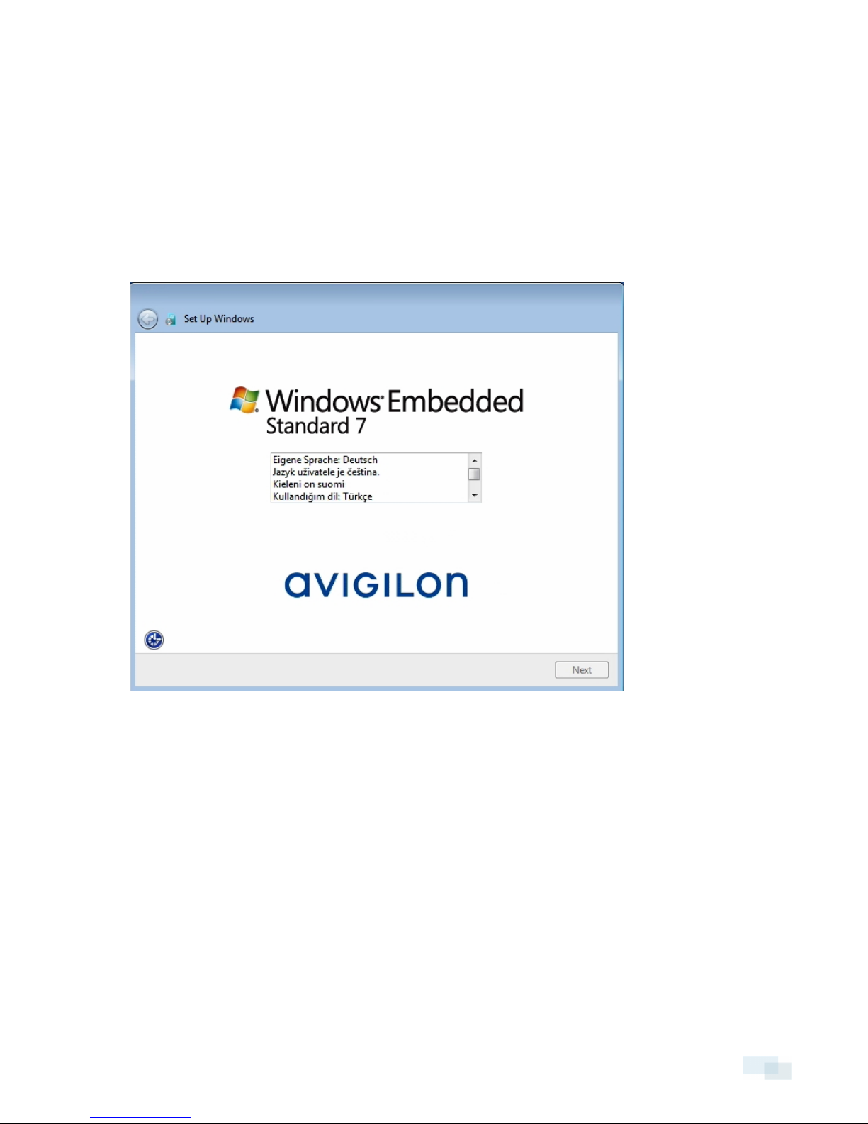
When you start the HD Video Appliance for the first time, you will need to configure the Windows operating
system that is installed on the appliance.
1. On the first screen, carefully scroll through the list and select your preferred language.
NOTE: You will not be able to change this setting after Windows applies your settings at the end of this
procedure.
Figure 1: The language selection screen during initialWindows set up.
2. Click Next.
3. Select your locale preferences then click Next.
4. Enter a user name for accessing the appliance. You can also enter a unique computer name or use the
default. When you are ready, click Next.
5. Set a password for the user name you entered on the previous screen. When you are ready, click Next.
6. On the following page is the end user license agreement for the Windows operating system. Review the
terms then select the I accept the license terms check box and click Next.
7. Select the correct date and time for the system then click Next.
8. Select the network mode for the appliance. The recommended option is Work Network.
Next, Windows applies all your settings and restarts. Once restarted, you will need to license your Avigilon
Control Center system.
Configuring Windows Embedded 7 2
Page 6

Licensing the Avigilon Control Center System
Before you can configure cameras and monitor live or recorded video, you will need to activate your Avigilon
Control Center software license. The license is provided with the appliance.
After the appliance reboots, the first screen you see is the Avigilon Control Center software license wizard.
Other parts of the Avigilon Control Center system may start while you perform this procedure, but you will not be
able to use any of the features until after license activation is complete.
1. Click License Activation.
2. On the following screen, select one of the following:
l Internet Activation – If the appliance has an internet connection, select this option to quickly
license the Avigilon Control Center software.
l Manual Activation – If the appliance is not currently connected to the internet or you plan to keep
the system in a private intranet, select this option.
Internet Activation
1. On the Enter Product Key page, enter your license key. A green check mark will appear beside your
license key when it is correct.
2. Click Next.
3. On the Product Registration page, enter your contact information to receive product updates. Then click
Next.
4. The Admin Tool connects to the Avigilon licensing server and activates the license.
When the Activation Succeeded message is displayed, click Finish.
Manual Activation
1. Click Step 1: Generate Activation File.
2. On the Enter Product Key page, enter your license key.
A green check mark will appear beside your license key when it is correct.
3. Click Next.
4. On the Select Activation File page, confirm where the activation file will be saved. Click [...] to navigate to
a different file location.
You can rename the activation file, but you must keep the .key extension.
5. Click Next.
On the following page, you will see the Activation File Saved message.
6. Find the saved activation file and copy the file to a computer with internet access.
3 Licensing the Avigilon Control Center System
Page 7

7. Open a web browser and go to http://activate.avigilon.com.
8. At the Avigilon License Activation web page, click Browse to locate your activation file then click
Upload.
9. The activated license file should download automatically. If not, allow the download to occur when you
are prompted.
10. Complete the product registration section to receive product updates from Avigilon, then click Register.
11. Find the downloaded license file and copy the file to the appliance.
12. If the Activation File Saved message is still displayed in the Add License wizard, click Next. Otherwise
skip this step.
13. Click Step 2: Add License File.
14. On the Import License File page, click [...] to locate the license file then click Next.
15. When the Activation Succeeded message is displayed, click Finish.
Adding Licenses
If you ever choose to upgrade your existing license to a different edition, you would need to perform the
licensing procedure again. However, you would access the Add License wizard from the Avigilon Control
Center Server Admin Tool software.
1. To open the Admin Tool, perform one of the following:
l Select All Programs or All Apps > Avigilon > Avigilon Control Center Server > Avigilon Control
Center Serve r Admin Tool.
l
From the appliance desktop, double-click .
2. In the Admin Tool window, select the Settings tab and click Licensing.
3. Click Add Lice nse.
4. Complete either the Internet Activation or Manual Activation procedure to add the new license to your
current system.
Adding Licenses 4
Page 8

Configuring the Network
Depending on how you intend to use the HD Video Appliance, you may choose to configure the network switch
component of the appliance differently.
The three most typical network configurations are:
1. No DHCP server — the HD Video Appliance and the connected cameras will run as a self contained
system without a DHCP server.
This configuration is most likely used by a small business that may not have a network infrastructure, and
prefers to use the HD Video Appliance like a traditional closed circuit surveillance system.
2. External DHCP server — the HD Video Appliance and the connected cameras will work with an existing
DHCP server on the network.
This configuration is most likely used by a small office that already has some network infrastructure that
will be used with the appliance, like a router that gives the office computers internet access.
3. Internal DHCP server — the HD Video Appliance will act as the local DHCP server for the connected
cameras and any other devices that may also be connected to the appliance.
NOTE: The HD Video Appliance is intended to be used for connecting and powering IP cameras, not for
general computer networking. However, if you prefer, the appliance can be configured to do so.
This configuration is most likely used by a small business that prefers to use the appliance switch
component instead of a router for connecting all network devices together. Other network devices can
include voice over ip (VoIP) phones or external network drives.
Complete the procedure that will configure your preferred network:
Configuring a No DHCP Network 5
Configuring an External DHCP Network 6
Configuring an Internal DHCP Network 7
Configuring a No DHCP Network
If you plan to connect cameras directly to the HD Video Appliance and run a self contained system, all you need
to do is connect cameras directly to the numbered ports.
5 Configuring the Network
Page 9
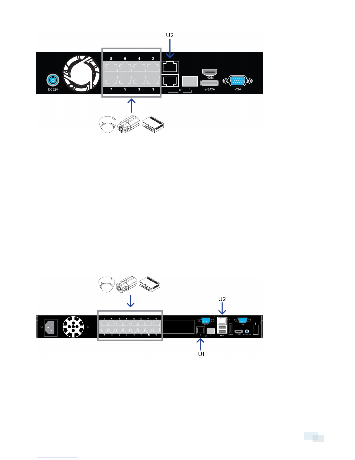
Figure 2: Example of no DHCP n etwork conn ection s on an 8 port HD Video Appliance.
Avigilon cameras are able to assign IP addresses to themselves when a DHCP server is not available through
Zero Configuration Networking (Zeroconf). The Avigilon Control Center software should automatically detect all
connected cameras through the 169.254.1.0/16 subnet.
If you would like to access the internet through the HD Video Appliance, you can add an internet connection to
the U2 port. The U2 port is separate from the numbered camera ports, so it will not interfere with video
recording.
After you connect cameras to the numbered ports, you can configure the Avigilon Control Center system. See
Configuring the Avigilon Control Center Software on page 12.
Configuring an External DHCP Network
If you already have a router, or switch, to connect your other network devices, you can connect the HD Video
Appliance directly to the router so that cameras can be addressed using the router's built-in DHCP service.
Figure 3: Example of external DHCP network conn ection s on a 16 port HD Video A ppliance
1. Connect a network cable from the router or switch to the appliance's U1 port.
2. Connect Avigilon cameras to the numbered ports.
Configuring an External DHCPNetwork 6
Page 10

3. If you would like to access the internet through the HD Video Appliance, you can add an internet
connection to the U2 port. The U2 port is separate from the numbered camera ports, so it will not interfere
with video recording.
After you've made the required network and camera connections, you can configure the Avigilon Control Center
system. See Configuring the Avigilon Control Center Software on page 12.
Configuring an Internal DHCP Network
If you plan to connect other network devices to the HD Video Appliance, you may need to set up the appliance
to be a DHCP server. Some network devices rely on a DHCP server to receive an IP address before it can work.
NOTE: After you setup the internal DHCP server, do not connect any external DHCP servers to the appliance or
there may be address conflicts and cause connection issues.
Tip: If you are only going to connect Avigilon cameras to the appliance, you do not need to set up a DHCP
server. For more information, see Configuring a No DHCP Network on page 5.
1. From the appliance, access the Windows Network Connections window.
l Select Start > Control Panel > Network and Sharing Center > Change adapter settings.
l From the Start menu, search for ncpa.cpl.
2. In the Network Connections window, right-click the Local Area Connection for the Intel Gigabit Network
Interface and select Properties.
Figure 4: The Network Connections dialog box
3. In the following dialog box, double-click Internet Protocol Version 4(TCP/IPv4).
7 Configuring an Internal DHCP Network
Page 11

4. Assign a static IP address for the appliance so that it can connect to the switch component.
By default, the appliance is not connected to the switch component. The appliance must be connected
to the switch component before you can configure the system to be a DHCP server.
The default IP address of the switch component is 192.168.50.1. Do not assign this address for the
appliance. You can use 192.168.50.2 or higher. It is recommended that you only change the last digit.
Figure 5: The Internet Protocol Properties dialog box
a. In the Use the following IP address field, enter 192.168.50.2 or the IP address you prefer.
b. In the Subnet mask field, enter 255.255.255.0 if it is not automatically entered.
c. Click OK to save your changes.
Configuring an Internal DHCP Network 8
Page 12

5. Open the Switch Management Console.
a. In a web browser, enter 192.168.50.1 into the address bar.
Figure 6: The Switch Management Console Log In screen
b. When the log in screen appears, enter the default ID and password:
l ID: admin
l Password: system
c. Click OK.
6. Once you are logged in, click DHCP Server Settings from the left menu pane.
9 Configuring an Internal DHCPNetwork
Page 13

7. In the Server State setting area, select Enable then click Update.
Figure 7: The DHCP Server Se ttings page
The appliance is now set to act as a DHCP server.
As you add cameras and network devices, the IP address for each item will be listed beside the
connected port number.
NOTE: The U1 port on the HD Video Appliance is not part of this DHCP setting. Only the PoE camera ports
broadcast DHCP.
8. Connect Avigilon cameras and other network devices to the numbered ports.
Each connected device is automatically assigned an IP address by the appliance.
Figure 8: Example cable connection s on an 8 port HD V ideo Appliance.
Configuring an Internal DHCP Network 10
Page 14

9. If you would like to access the internet through the HD Video Appliance, you can add an internet
connection to the U2 port. The U2 port is separate from the numbered camera ports, so it will not interfere
with video recording.
After you've made the required network and camera connections, you can configure the Avigilon Control Center
system. See Configuring the Avigilon Control Center Software on page 12.
11 Configuring an Internal DHCPNetwork
Page 15

Configuring the Avigilon Control Center Software
After you set up and license the HD Video Appliance, it is recommended that you complete the following steps
to configure the Avigilon Control Center system.
For more information about any of the following procedures, see the help files provided with the Avigilon
Control Center Client software.
Starting Up and Shutting Down the Avigilon Control Center Client Software 12
Logging Into and Out of a Site 13
Changing the Administrator Password 14
Connecting Cameras to the Avigilon Control Center System 14
Setting the Recording Schedule 15
Setting Data Aging 16
Adding Users and Groups 17
Advanced Settings 19
Starting Up and Shutting Down the Avigilon Control Center Client
Software
After you install the Avigilon Control Center Client software, start the application and access the HD Video
Appliance.
Starting Up the Client Software
Perform one of the following:
l In the Start menu, select All Programs or All Apps > Avigilon > Avigilon Control Center Client.
l
Double-click the shortcut icon on the desktop.
l From the AvigilonControl Center Admin Tool, click Launch Control Center Client. For more information,
see the AvigilonControl Center Server User Guide.
When you are prompted, log in to your Site. You can only access cameras and video after you log in.
Once the application has started, it will automatically display a list of all the Sites that are connected to the same
network, including the HD Video Appliance. You will be prompted to log in to all Sites.
Shutting Down the Client Software
1.
In the top-right corner of the Client software, select > Exit.
2. When the confirmation dialog box appears, click Yes.
Configuring the Avigilon Control Center Software 12
Page 16

Logging Into and Out of a Site
After you start the Client software, you are immediately asked to log in to a Site. By default, the HD Video
Appliance is automatically added to the system as a server within a Site of the same name.
The default username is administrator with no password.
Logging In
1. Open the Site Login tab. The Site Login tab is automatically displayed if you are launching the Client
software for the first time.
To manually access the Site Login tab, do one of the following:
l
From the top-right corner of the window, select > Log In....
l
From the top of the application window, click to open the New Task menu then click
2. On the left side of the Site Login tab, select one or more Sites.
If the Site you want to log into is not shown, click Find Site... to discover the Site.
3. Enter your username and password for the selected Sites.
Or, select the Use current Windows credentials check box to automatically use the same username and
password as your computer.
NOTE: If you are unable to login using your current Windows credentials, your system may be using
Kerberos as a network authentication protocol. Contact your network administrator for help.
4. Click Log In.
You are logged into the selected Sites.
If you want to be notified when new or disconnected Sites come online, select the Notify me when additional
sites become available check box.
If you want to see the login page each time you launch the Client software, select the Show this tab on startup
check box. If you prefer not to login each time, you can disable this option and configure automatic login from
the Client Settings... dialog box.
Logging Out
You can log out of one or all Sites at any time.
To... Do this...
Log out of one or select Sites
Log out of all Sites
l In the System Explorer, select one or more Sites then right-click and
select Log Out.
1.
In the top-right corner of the Client, select > Log Out.
2. In the confirmation dialog box, click Yes.
13 Logging Into and Out of a Site
Page 17

Changing the Administrator Password
After you log in for the first time, it is recommended that you change the default administrator password.
1.
At the top of the application window, click to open the New Task menu. When the menu appears,
click .
2.
In the Setup tab, click .
3.
In the following dialog box, select the administrator user name and click .
4. Click Change Password....
5. In the following dialog box, enter a new password then confirm the new password.
6. Click OK.
Tip: If you forget the default administrator password, resetting the password requires restoring the factory
default settings on every server in the Site. To avoid this issue, it is highly recommended that you create at least
one other administrator level user as a backup.
Connecting Cameras to the Avigilon Control Center System
After all the cameras in your system have been physically connected to the HD Video Appliance, you need to
connect the cameras to the Avigilon Control Center system so that video can be recorded and indexed for
search.
1.
In the Site Setup tab, click .
The Connect/Disconnect Cameras... tab is displayed.
2. In the Discovered Cameras area, select one or more devices then click Connect....
Tip: You can also drag the device to a server on the Connected Cameras list.
3. In the Connect Camera dialog box, select the server you want the device to connect to.
NOTE: If you are connecting multiple devices, all the cameras must use the same connection settings.
4. If you are connecting a third-party device, you may choose to connect the device by its native driver. In
the Camera Type: drop down list, select the device's brand name. If there is only one option in the drop
down list, the system only supports one type of driver from the device.
5. In the Connection Type: drop down list, select Primary. The device will automatically connect to this
server if they are in the same network.
If you are creating a failover connection, select Secondary or Tertiary.
6. In the License Priority: drop down list, select the appropriate license priority. The highest priority is 1 and
the lowest priority is 5.
NOTE: This option is only available if you are connecting to a secondary or tertiary server.
Changing the Administrator Password 14
Page 18

The License Priority: setting decides the order that devices are connected to the server. The server will
try to connect cameras with a higher priority before cameras with lower priority. If the server does not
have enough camera channel licenses, low priority devices may not be connected. A camera channel
license is only used when the device actually connects to the server.
7. If the camera supports a secure connection, the Camera Control: drop down list is displayed. Select one
of the following options:
NOTE: The setting may not be displayed if the camera only supports one of the options.
l Secure — The system will protect and secure the camera's configuration and login details. This
option is selected by default.
l Unsecure — The camera's configuration and login details will not be secured and may be
accessible to users with unauthorized access.
Cameras with a secure connection are identified with the icon in the Status column.
8.
If it is not displayed, click to display the Site View Editor and choose where the device appears in the
System Explorer.
l If your Site includes virtual sub-sites, select a location for the device. The list on the right updates to
show what is stored in that directory.
l In the Site directory, drag the device up and down to set where it is displayed.
l If you are connecting multiple devices at the same time, the selected devices must be assigned to
the same sub-site
Tip: If the Site you want is not listed, you may need to connect the device to a different server. Make sure
the selected server is connected to the Site you want.
9. Click OK.
10. If the device is password protected, the Camera Authentication dialog box appears. Enter the device's
username and password then click OK.
Setting the Recording Schedule
Once all the cameras have been connected, you can set when you want each camera to record video.
By default, all connected cameras are set to record when events are detected by the system. You can skip this
procedure if you prefer to keep the default settings.
Before you can assign a recording schedule, you must create a template. The template allows you to assign the
same schedule to multiple cameras.
Creating a Recording Template
The events that can be selected for the template depend on the licensed features in your system.
1.
In the server Setup tab, click . The Recording Schedule dialog box is displayed.
2. Click Add Template below the Templates: list.
15 Setting the Recording Schedule
Page 19

3. Enter a name for the New Template.
4. Click the Set Area button, then click or drag the cursor across the Recording Mode: timeline to set the
types of events that the cameras will record throughout the day. Individual rectangles on the Recording
Mode: timeline are colored when they have been selected.
The Recording Mode: options include:
l Continuous — record video constantly.
l Motion — Only record video when motion is detected.
l Digital Inputs — Only record video when a digital input is activated.
l Alarms — Only record video when an alarm is activated.
l POS Transactions — Only record video when a point of sale (POS) transaction is made.
l License Plates — Only record video when a license plate is detected.
5. To disable recording in parts of the template, click the Clear Area button then click or drag the cursor
across the timeline to remove the set recording areas.
6. If cameras are not recording in Continuous mode all day, you can set cameras to record reference
images between events in the recording schedule.
l Select the Record a reference image every: check box then set the time between each
reference image.
Setting Up a Weekly Recording Schedule
You can set up a weekly recording schedule by applying templates to cameras for each day of the week.
1.
In the server Setup tab, click . The Recording Schedule dialog box is displayed.
2. Select a template from the Templates: list.
3. In the Default Week area, click the days of the week this template applies to for each camera.
Figure 9: The Recording Schedu le dialog box: Default Week
4. Click OK.
Setting Data Aging
Data aging defines how long recorded video is stored and the quality of the video as it ages over time. In the
Avigilon Control Center system, the recorded image rate is slowly reduced so that recorded video can be
viewed over a longer period of time while still making room for new recordings. You can adjust how long the full
image rate video is kept, so that you have the best quality video when you need it.
Setting Up a WeeklyRecordingSchedule 16
Page 20

The amount of data aging that is available depends on the camera you have connected to your system:
l For JPEG2000 or JPEG compression cameras, Data Aging is available at three rates:
l Full Image Rate and Resolution keeps recordings at their original quality.
l Half Image Rate discards half of the recorded data to make room for new recordings.
l Quarter Image Rate keeps 1/4 of the original recorded data so that you can still see older video.
l For H.264 cameras that support Data Aging, Data Aging is available at two rates:
l Full Image Rate and Resolution keeps the original high quality video and the secondary stream of
low resolution video.
l Low Resolution only keeps the secondary stream of low resolution video.
NOTE: The Data Aging can only occur when the secondary stream is enabled.
l For H.264 cameras that do not support Data Aging, only the Full Image Rate and Resolution video is kept.
By default, the system is set to keep recorded video for the maximum amount of time based on the available
storage.
NOTE: The listed Total Record Time is an estimate only.
1.
In the server Setup tab, click .
The Recording and Bandwidth dialog box is displayed.
The Data Aging column shows an estimate of the recording time that is available at each image rate,
given the amount of space on the recording device.
2. In the Data Aging column, move the sliders to adjust the amount of time video is stored at each image
rate.
l To change the data aging settings for all linked cameras, move the slider for one linked camera
and all linked cameras will be updated.
l To change the data aging setting for one camera, break the camera's link to other cameras by
clicking the icon to the left of its name, then make your changes.
3. In the Max. Record Time, manually enter a maximum record time or select one of the options from the
drop down list for each camera.
NOTE: If the time estimated in the Total Record Time column is shorter than what is set in the Max. Record
Time column, the camera's actual recording time will be shorter than the Max. Record Time.
4. Click OK.
Adding Users and Groups
If there will be other people using the system, you may want to add them as separate users rather than giving
them access through the default administrator account.
Before you can add individual users, you will need to add permission groups that define what users have access
to. By default, the system has the following groups:
17 Adding Users and Groups
Page 21

l Administrators — has access to everything in the system.
l Power Users — has access to most features in the system except for the ability to import and export
settings.
l Restricted Users — has access to live video only and can control audio and digital outputs.
l Standard Users — has access to live and recorded video, but cannot make any Setup changes.
It is highly recommended that you add at least one other user to the Administrators group. In the event you
forget the default administrator password, the second administrator user can be used to reset the password. If
you do not have a second administrator user, you may need to completely reset the system.
Adding Groups
1.
In the Site Setup tab, click .
2.
In the following dialog box, select the Groups tab and click .
3. In the pop-up dialog box, select an existing group to use as a template for your new group, then click OK.
4. In the Edit Group dialog box, complete the following:
a. Give the new group a name.
b. Select a rank for the group from the Rank: drop down list. To edit or view the entire Corporate
Hierarchy, click .
c. Select the required Group Privileges: and Access Rights: for the group. Clear the check box of any
feature or device that you do not want the group to have access to.
5. Select the Members tab to add users to the group.
If a user is added to the group through the Add User dialog box, the user is automatically added to the
group's Members list.
a.
Click .
b. Select the users that should be part of this new group. Only users that have been added to the Site
are displayed.
Tip: Enter the name of a user in the Search... field to locate specific users.
c. Click Add. The users are added to the Members list.
6. Click OK to save the new group.
Adding Users
1.
In the Site Setup tab, click .
2.
In the Users tab, click .
3. When the Add User dialog box appears, complete the User Information area.
4. If you don’t want this user to be active yet, select the Disable user check box. Disabled users are in the
system but cannot access the Site.
Adding Groups 18
Page 22

5. In the Login Timeout area, select the Enable login timeout check box to set the maximum amount of time
the Avigilon Control Center Client software can be idle before the user is automatically logged out of the
application.
6. In the Password area, complete the following fields:
l Password: — enter a password for the user.
l Confirm Password: — re-enter the password.
l Require password change on next login — select this check box if the user must replace the
password after the first login.
l Password Expiry (Days): — specify the number of days before the password must be changed.
l Password never expires — select thischeck box if the password never needs to be changed.
7. In the Member Of tab select the check box beside each access group the user belongs to.
The other columns display the permissions that are included in the selected groups.
8. Click OK. The user is added to the Site.
Repeat this procedure to add all the users that are required.
Advanced Settings
After you've set up all the required settings in the Avigilon Control Center Client software, the system can start
running.
In the following list are some advanced settings you can use to further customize your system. See the
application Help files for details about how to configure each setting.
l Adjust camera settings
l If camera video looks slightly blurry or unclear, you can adjust the camera's Image and Display
settings.
l If you want the camera to record at a different image rate, you can adjust the camera's
Compression and Image Rate settings.
l To reduce the amount of ambient motion detection for a specific camera, you can adjust the
Motion Detection settings.
l To maintain the privacy of certain areas, you can set Privacy Zones in the camera's field of view so
that private spaces are never recorded.
l Add a joystick
l If you prefer to control PTZ cameras with a standard USB joystick, you can install and set up a
joystick from the Client Settings... dialog box.
l If you prefer use the Avigilon Professional JoystickKeyboard with the Control Center Client
software, you can install and setup the joystick keyboard from the Client Settings... dialog box.
l Email notifications
l You can set up an SMTP email server to send you messages when system events occur.
l If you have a Standard Edition system, you can set up detailed rules to notify you when specific
events occur.
19 Advanced Settings
Page 23

l Setup the Gateway
l The Avigilon Control Center Gateway software allows you to access video from a remote web
browser or mobile device. If the Gateway software is not set up, you cannot access video outside
of your local network.
l Install the Avigilon Control Center Mobile app on your mobile device so that you can monitor live
and recorded video anywhere.
Advanced Settings 20
Page 24

LED Indicators
The following list describes what the LEDs on the front of each HD Video Appliance indicate.
l
Appliance Status — The LED is on if the appliance is powered and running.
l 1 to 8/16/24 — The connection status of each camera that is connected to the appliance.
l Orange — The LED is orange if the camera is only using the switch for a network connection.
l Green — The LED is green if the camera is using the switch for PoE power and as a network
connection.
l
PoE Status — The LED will start to blink if the appliance starts to reach its PoE output capability.
l
Hard Drive Status — The LED will blink if the hard drives are in use. If the LED is off, the hard drives are
not being detected.
l
/ Network Status — The network connection speed at the U1 or U2 ports.
l Orange — The LED is orange if the network speed is 1000 Mbps.
l Green — The LED is green if the network speed is 1/100 Mbps.
21 LEDIndicators
Page 25

Restarting the Operating System
If the operating system ever freezes or displays a fatal system error, you can restart the operating system by
using the reset switch on the front of the appliance.
NOTE: When you use the reset switch, the appliance must be powered.
The operating system reset will not affect the switch component or the connected cameras.
l On the 8 port model, the reset switch is located at the front of the appliance and is the small unlabeled
hole between the USB ports and the status LEDs.
l On the 16 and 24 port model, the reset switch is locate at the front of the appliance and is the small
unlabeled hole between the and status LEDs.
Once you've found the reset switch on the appliance, complete the following steps:
1. Using a straightened paperclip or similar tool, gently press and hold the reset switch.
CAUTION — Do not apply excessive force. Inserting the tool too far will damage the appliance.
2.
Do not release the reset switch until the monitor connected to the appliance turns off, or the Hard
Drive Status LED stops blinking.
Once you release the reset switch, the operating system should automatically restart.
Restarting the Operating System 22
Page 26

Replacing a Hard Drive
NOTE: 16 and 24 port models only. This procedure is for replacing the storage drives. If you experience an
operating drive failure or any drive issue with the 8 port model, contact Avigilon Technical Support immediately
for assistance.
If the Avigilon Control Center software starts to perform excessively slow or becomes prone to freezing, these
may be signs of a potential hard drive failure.
If the HD Video Appliance starts to beep and does not stop, a drive has failed.
To confirm which hard drive the issue may be with, open the JMicron RAID Manager application.
1. From the Windows Start menu, select All Programs > JMicron HW RAID Manager > JMicron HW Raid
Manager. The JMicron application may be slow to start.
2. In the Basic Mode tab, select RAID and Disk Information if it is not automatically displayed.
You need to replace the hard drive if:
l The RAID status is Degraded.
l The failed Disk is highlighted in red.
In the JMicron HW RAID Manager, the hard drives are listed as Disk 1 to 4. From the front of the appliance, Disk 1 is
the hard drive installed on the far left and Disk 2 - 4 are installed beside each other from left to right.
If more than one drive has failed, immediately shut down your system and contact Avigilon Technical Support for
possible recovery instructions.
Important: Always replace a hard drive with one of the same size, make and model, or the appliance will
continue to fail.
To replace a failed hard drive, complete the following steps.
1. Shut down the HD Video Appliance
2. Disconnect all cable connections from the appliance. This includes all cameras. It is highly recommended
that you do not reconnect cameras until after completing this procedure.
3. Remove the screws from the top, left and right sides of the appliance.
Be aware that the top screws are different from the side screws.
23 Replacing a Hard Drive
Page 27

4. Standing before the front of the appliance, pull the appliance cover towards you until it slides off.
Figure 10: Pull the cover off the HD Video Appliance from the front.
Once the cover has been removed, you will see the four hard drives at the front. The hard drives are
numbered Disk 1 to 4 from left to right.
Figure 11: HD Video Appliance with the cove r removed.
5. Remove the two silver screws attached to the hard drive base plate at the front of the appliance.
6. From the back of the hard drive, push the hard drive towards you until it is released from the appliance.
Replacing a Hard Drive 24
Page 28

7. Lift the hard drive out of the appliance.
8. Turn the hard drive upside down, and remove the four screws holding the hard drive to the base plate.
Figure 12: Hard drive removed from the base plate.
9. Remove the failed hard drive.
10. Attach the new hard drive to the base plate.
11. Place the new hard drive into the appliance, then push it into the appliance connector before you screw
the hard drive base plate into place.
12. Reinstall the appliance cover.
13. Connect your mouse, keyboard and monitor back to the appliance.
14. Connect power to the appliance and allow the system to restart.
The system will immediately begin to rebuild the RAID.
15. When prompted, allow Windows to start normally.
16. Once Windows has loaded, select Start >All Programs > JMicron HW RAID Manager > JMicron HW Raid
Manager.
17. In Basic Mode, select the RAID and Disk Information tab and confirm that the RAID status is Rebuilding %.
Important: While the RAID is being rebuilt, do not reconnect cameras, open other applications or allow
other network instances of the Avigilon Control Center Client software to connect to the appliance. If you
try to resume normal operations while the RAID rebuilds, you may lose recorded data and cause further
issues in the appliance.
The RAID may take up to 100 hours to rebuild depending on the total amount of recorded data and the
load on the storage subsystem.
When the rebuilding process is complete, the RAID status changes to Normal.
18. Once the system has finished rebuilding, reconnect all your cameras and resume normal operations.
25 Replacing a Hard Drive
Page 29

Limited Warranty & Technical Support
Avigilon warrants to the original consumer purchaser, that this product will be free of defects in material and
workmanship for a period of 3 years from date of purchase.
The manufacturer’s liability hereunder is limited to replacement of the product, repair of the product or
replacement of the product with repaired product at the discretion of the manufacturer. This warranty is void if
the product has been damaged by accident, unreasonable use, neglect, tampering or other causes not arising
from defects in material or workmanship. This warranty extends to the original consumer purchaser of the
product only.
AVIGILON DISCLAIMS ALL OTHER WARRANTIES EXPRESSED OR IMPLIED INCLUDING, WITHOUT LIMITATION,
ANY IMPLIED WARRANTIES OF MERCHANTABILITY OR FITNESS FOR A PARTICULAR PURPOSE, EXCEPT TO
THE EXTENT THAT ANY WARRANTIES IMPLIED BY LAW CANNOT BE VALIDLY WAIVED.
No oral or written information, advice or representation provided by Avigilon, its distributors, dealers, agents or
employees shall create another warranty or modify this warranty. This warranty states Avigilon’s entire liability
and your exclusive remedy against Avigilon for any failure of this product to operate properly.
In no event shall Avigilon be liable for any indirect, incidental, special, consequential, exemplary, or punitive
damages whatsoever (including but not limited to, damages for loss of profits or confidential or other
information, for business interruption, for personal injury, for loss of privacy, for failure to meet any duty including
of good faith or of reasonable care, for negligence, and for any other pecuniary or other loss whatsoever) arising
from the use of or inability to use the product, even if advised of the possibility of such damages. Since some
jurisdictions do not allow the above limitation of liability, such limitation may not apply to you.
This Limited Warranty gives you specific legal rights and you may also have other rights which vary from
jurisdiction to jurisdiction.
Warranty service and technical support can be obtained by contacting Avigilon Technical Support by phone at
1.888.281.5182 or via email at support@avigilon.com.
Limited Warranty & Technical Support 26
 Loading...