

Page 1

User Guide
Avigilon Artificial Intelligence Appliance
VMA-AIA1-CG1/CG2
Page 2

©2018,Avigilon Corporation. All rights reserved. AVIGILON, the AVIGILON logo, AVIGILON CONTROL CENTER
and AVIGILON APPEARANCESEARCH are trademarks of Avigilon Corporation. MacOS, FINDER and
MACINTOSH are registered trademarks of Apple Inc. FIREFOX is a registered trademark of Mozilla Foundation.
Other names or logos mentioned herein may be the trademarks of their respective owners. The absence of the
symbols ™ and ® in proximity to each trademark in this document or at all is not a disclaimer of ownership of the
related trademark. Avigilon Corporation protects its innovations with patents issued in the United States of
America and other jurisdictions worldwide (see avigilon.com/patents). Unless stated explicitly and in writing, no
license is granted with respect to any copyright, industrial design, trademark, patent or other intellectual
property rights of Avigilon Corporation or its licensors.
This document has been compiled and published using product descriptions and specifications available at the
time of publication. The contents of this document and the specifications of the products discussed herein are
subject to change without notice. Avigilon Corporation reserves the right to make any such changes without
notice. Neither Avigilon Corporation nor any of its affiliated companies: (1) guarantees the completeness or
accuracy of the information contained in this document; or (2) is responsible for your use of, or reliance on, the
information. Avigilon Corporation shall not be responsible for any losses or damages (including consequential
damages) caused by reliance on the information presented herein.
Avigilon Corporation
avigilon.com
PDF-VMA-A1A1-A
Revision: 1 - EN
20180920
ii
Page 3

Table of Contents
Introduction 1
Overview 1
Front View 1
Back View 2
System Requirements 2
Camera Frame Rate 2
Web Browser 2
Installation 4
Package Contents 4
Installing the Rack Rails and Cable Management Arm 4
Installing the Bezel 4
Connecting Cables 5
Starting the Avigilon AIAppliance for the First Time 6
Troubleshooting Installation—Cannot Discover the Device 7
Troubleshooting Installation—Networking 7
Installing and Starting the Avigilon Control Center ™ Client 8
Starting Up and Shutting Down the ACC Client Software 8
Starting Up the Client Software 8
Shutting Down the Client Software 8
Logging In to and Out of a Site 8
Logging In 9
Logging Out 9
Moving the Avigilon AIAppliance to a Site 10
Configuring the Appliance 11
Accessing the Web Interface 11
Web Interface Launch Page 11
Server Panel 12
Logs Panel 12
Device Panel 13
Network Panel 14
System Logs Panel 15
Configuring the Avigilon Control Center Software 16
Changing the Site Administrator Password 16
Accessing the Setup Tab 16
iii
Page 4

Enabling Server Analytics 17
Analytic Settings 17
Advanced Features 19
LED Indicators 20
Diagnostic Indicators 20
Power Status Indicators 20
Upgrading the Firmware 22
Restoring to Factory Default Settings 23
iv
Page 5

Introduction
The Avigilon Artificial Intelligence Appliance (Avigilon AIAppliance) provides Avigilon's patented self-learning
video analytics and Avigilon Appearance Search™ on existing multi-megapixel IPcameras that are not already
analytic-enabled when paired with the Avigilon Control Center software (ACC). The Avigilon AIAppliance
features:
l Avigilon's self-learning video analytics with no manual calibration, as available on Avigilon analytic
cameras.
l Pre-integrated with Avigilon Control Center High Definition Network Video Management System for
simple setup.
l High capacity video analytic processing that accepts video sources from 320 × 240 to 3264 × 2448
pixels.
This guide describes how to configure the system after the Avigilon AIAppliance has been powered and is
connected the local area network.
Overview
Front View
1.
Diagnostic indicators
Provides information about system operations.
For more information, see LED Indicators on page20.
2.
Bezel
Must be installed on site.
3.
Bezel Lock
Protects against unauthorized physical access.
Introduction 1
Page 6
4.
Power button
Controls the power supply to the appliance.
5.
Video connector
Accepts a VGA monitor connection.
6.
Information tag
Pull-out tag that provides the product service details and support information.
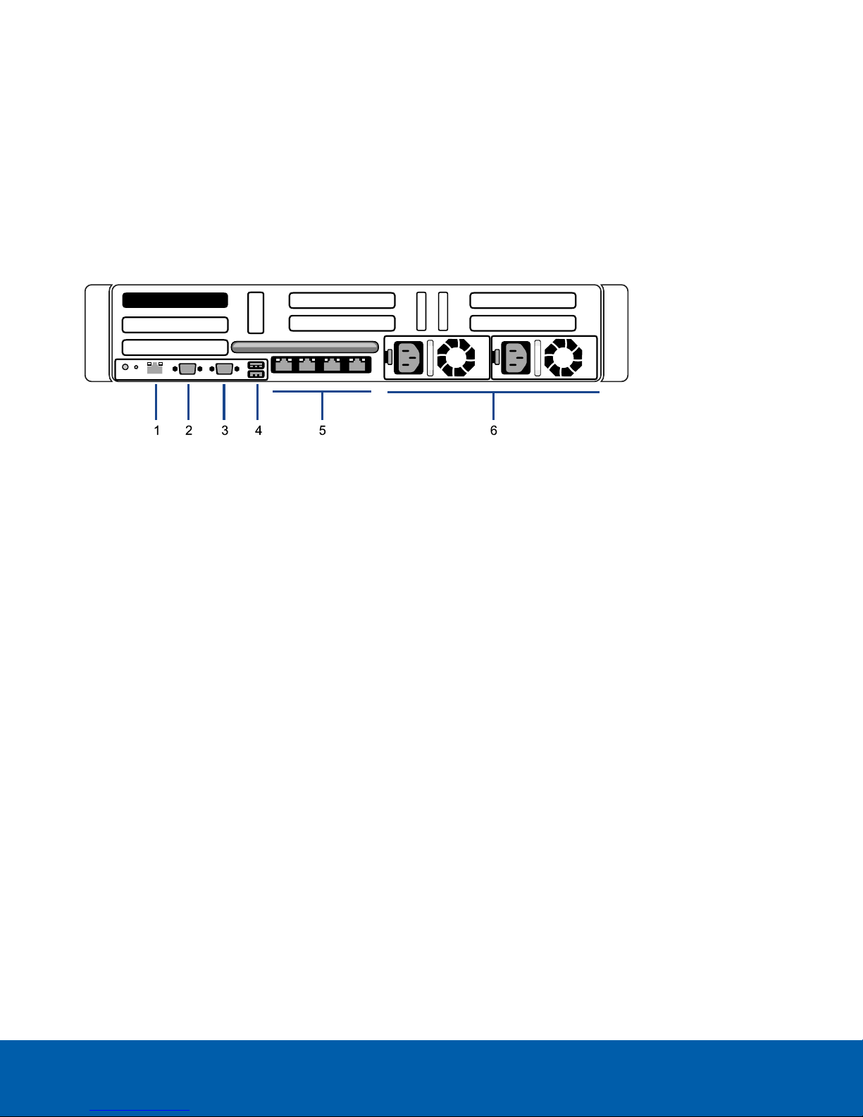
Back View
1.
Out-of-Band Management (OOBM) connector
Accepts an OOBM RJ-45 connection.
2.
Serial connector
Accepts connections to serial devices.
3.
Video connector
Accepts a VGA monitor connection.
4.
USB connectors
Accepts USB connections to external devices.
5.
Four (4) RJ-45 1 Gbps Ethernet ports
Accepts Ethernet connections to multiple networks. Any port can be used.
6.
Power supply
Two hot swappable redundant power supply.
System Requirements
Camera Frame Rate
The Avigilon AIAppliance can provide analytics for non-analytics cameras. For optimal analytics performance,
the source camera should stream a minimum of 10 frames per second (fps).
Web Browser
Back View 2
Page 7

Basic administration settings for the Avigilon AIAppliance are managed through its Web Interface. However,
most configuration is done with the ACC Client.
The Web Interface can be accessed from any Windows®, Mac or mobile device using any of the following web
browsers:
l Mozilla Firefox® browser version 3.6 or later
l Google Chrome™ browser 8.0 or later
l Microsoft Edge™ browser 25 or later
l Safari® 5.0 or later
l Chrome on Android™ 2.2 or later
l Safari on Apple® iOS 5 or later.
l Windows Internet Explorer® browser version 7.0 or later
NOTE: Your web browser must be configured to accept cookies or the Web Interface will not function correctly.
Web Browser 3
Page 8
Installation
Before starting the installation, copy down the serial number and MAC address from the label on the underside
of the appliance. You will need this information during the installation procedure.
Package Contents
Ensure the package contains the following:
l Avigilon Artificial Intelligence Appliance
l Rack sliding rail assembly kit
l Cable management arm assembly kit
l Bezel and key
l Power cables (may be provided in a separate box)
Installing the Rack Rails and Cable Management Arm
If the Avigilon AIAppliance will be kept in a server rack, install the Rack Sliding Rails and the Cable Management
Arm provided in the appliance package. Follow the procedures outlined in the Rack Installation Instructions and
the CMA Installation Instructions provided in the assembly kits.
NOTE: The supplied Rack Sliding Rails are compatible with square and round hole racks.
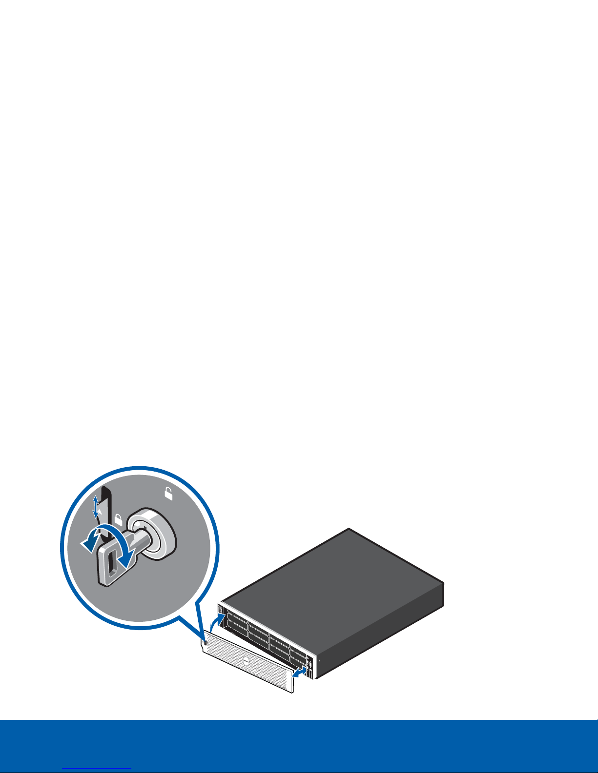
Installing the Bezel
The bezel can be installed on the front of the Avigilon AIAppliance to help protect against unauthorized access.
Installation 4
Page 9

1. Align and insert the right end of the bezel until it clicks into place.
2. Push the left end of the bezel into the front of the unit until it clicks into place.
3. Use the provided key to lock the bezel.
Connecting Cables
Refer to the diagrams in Overview on page1 for the location of the different connectors. Make the following
connections, as required:
1. Connect the Avigilon AIAppliance to your network using an Ethernet cable.
NOTE: It is recommended that the Avigilon AIAppliance follow a similar network configuration to the site
NVRs. You can connect up to 4 Ethernet cables.
2. Connect a power cable to each power supply at the back of the Avigilon AIAppliance.
ConnectingCables 5
Page 10

Starting the Avigilon AIAppliance for the First Time
After powering on the Avigilon AIAppliance, complete the following procedure:
1. Connect a port on the Avigilon AIApplianceto the local network with an Ethernet cable.
2. Press the power button on the front of the Avigilon AIAppliance and wait for the appliance to start up. .
Check that the appliance LED indicators display the correct status. See LED Indicators on page20 for
more information.
3. On a network workstation, discover the appliance. Use File Explorer on a Windows computer or Finder®
on a Macintosh computer. You are looking for a device labeled “VMA-AIA1-CGx-xxxxxxxxxx”, where
xxxxxxxxxx is the serial number of your appliance. If you cannot locate the appliance, see Troubleshooting
Installation—Cannot Discover the Device on the next page.
4. Click to open the device in a supported web browser (see System Requirements on page2).
Important: The Avigilon AIAppliance is configured with a self-signed certificate, which generates a
connection warning in the web browser.
5. Click past any connection messages displayed by the browser. You will see two warning messages that
differ slightly depending on the browser. If the browser is:
l Chrome—Click Advanced on the first screen and Proceed to <IPaddress>(unsafe) on the second
screen.
l Firefox—Click Advanced on the first screen and on the second screen click Add Exception, check
Permanently store this exception, and click Confirm Security Exception.
6. When you are prompted by the Web Interface, enter a new password for the administrator username.
The Strength meter measures the complexity of your password: Red is too simple, yellow is reasonably
complex, and green is complex. Complexity measures the difficulty to discover your password, not how
secure your password is. A complex password is recommended.
The page refreshes and you are prompted to log in.
7. Enter administrator as the username and your new password.
The Dashboard panel of the Web Interface is displayed.
8. Set the language for the Web Interface, and a user-friendly hostname and the time zone. In the navigation
sidebar, click Device to open the Device panel . In the:
a. General pane, select the Language from the drop-down.
b. Hostname pane, optionally replace the serial number of the appliance with a descriptive hostname
for the appliance.
c. Time pane, specify the Time Zone and identify the time source in the NTP drop-down and Servers
list.
For more information see Device Panel on page13.
Starting the Avigilon AIAppliance for the First Time 6
Page 11

9. Select how the appliance obtains IPaddresses from the network. On the navigation sidebar, click
Network to open the Network panel. For each network port used, select Automatic or manually enter the
settings.
For more information, see Network Panel on page14.
For more information about the Web Interface, see Configuring the Appliance on page11
Troubleshooting Installation—Cannot Discover the Device
If you cannot discover the device using File Explorer (Windows) or Finder (Macintosh) during the hardware
installation and it is connected to your network, try the following:
l Access the appliance from your web browser using the URLhttps://VMA-AIA1-CGx-<serial number>
l Use the Address Resolution Protocol (ARP) to determine the IP address for the device:
1. Locate and copy down the MAC Address (MAC) listed on the Serial Number Tag for reference.
2. Open a Command Prompt window and enter the following command:
arp -a
3. Scroll through the response and look for the IP address corresponding to the MAC address.
l Discover the DHCP-assigned IPaddress from the ACC Client software:
1. Download and install the ACC Client software on to the configuration laptop.
The ACC Client software can be downloaded from the Avigilon website: avigilon.com.
2. Launch the ACC Client software.
3. Log into the site that uses this naming convention: VMA-AIA1-CGx-xxxxxxxxxx.
The default username is administrator, with no password.
NOTE: The username and password for the Web Interface application is separate from the
administrator username and password for the ACC Client. To change the password for the ACC
application, see Changing the Site Administrator Password on page16.
4. Display the server Setup tab.
At the top of the window, the appliance IP address is displayed.
5. Open a web browser and enter the IP address in this format: https://<IP address>.
6. Continue the remaining steps for installing the appliance.
Of none of the above suggestions resolve the problem, contact Avigilon Technical Support.
Troubleshooting Installation—Networking
By default, the Avigilon AIAppliance acquires an IP address on the network through DHCP. If you need to set up
the Avigilon AIAppliance to use a static IP address or any specific network configuration, see the Windows Help
and Support files for more information.
Troubleshooting Installation—Cannot Discover the Device 7
Page 12

Installing and Starting the Avigilon Control Center ™
Client
To install the ACC Client software:
1. Open a web browser from a network workstation with network access to the Internet.
2. Download the ACC Client software from the Avigilon website: avigilon.com.
3. Install the ACC Client software on a network workstation with network access to the device
Complete the following procedures to start, log in to, and log out of the ACC Client software .
Starting Up and Shutting Down the ACC Client Software
After you install the ACC Client software, start the application and log in to the Avigilon AIAppliance.
The ACC Client software should start automatically when your Windows workstation starts. Refer to the following
steps if it doesn't.
Starting Up the Client Software
Perform one of the following:
l In the Start menu, select All Programs or All Apps > Avigilon > Avigilon Control Center Client.
l
Double-click or desktop shortcut icon.
When you are prompted, log in to your site. You can only access cameras and video after you log in.
The “Select one or more sites to log in.” message appears. If you are connected only to the new device, one
site is listed in the left navigation panel. Otherwise, all the sites that are connected to the same network are
listed. The site name of your new device is the hostname that you assigned in the Web Interface. You can use
Find Site… to specify the IPaddress or hostname of the device if the list is long.
Shutting Down the Client Software
1.
In the top-right corner of the Client software, select > Exit.
2. When the confirmation dialog box appears, click Yes.
Logging In to and Out of a Site
After you start the ACC Client software, you are immediately asked to log in to a site.
By default, the Avigilon AIAppliance appears as a site with the same name as the hostname.
The default username is administrator with no password.
Installing and Starting the Avigilon Control Center ™ Client 8
Page 13

Logging In
1. Open the Site Login tab. The Site Login tab is automatically displayed if you are launching the Client
software for the first time.
To manually access the Site Login tab, do one of the following:
l
From the top-right corner of the window, select > Log In….
l
From the top-left corner of the application window, click to open the New Task menu, then
click .
2. On the left side of the Site Login tab, select one or more sites.
If the site you want to log into is not shown, click Find Site… to discover the site.
3. Enter your username and password for the selected sites.
4. Click Log In.
5. If Two-Factor Authentication is required, a dialog box is displayed.
a. The first time you log in, a QRcode is displayed. On your mobile device, scan the QR code with a
TOTP authenticator app like the Google Authenticator™ mobile app or the FreeOTP Authenticator™
mobile app. If you cannot scan the QRcode, enter the 20-character key into the authenticator app.
The authenticator app will display a 6-character verification code.
b. The next time you log in, use the authenticator app to get your verification code.
c. Enter the code in the Verification Code: box.
Tip: Select the Trust this device for 30 days check box to avoid entering a verification code each
time you log in.
d. Click OK.
You are logged in to the selected sites.
If you want to be notified when new or disconnected sites come online, select the Notify me when additional
sites become available check box.
If you want to see the login page each time you launch the Client software, select the Show this tab on startup
check box. If you prefer not to login each time, you can disable this option and configure automatic login from
the Client Settings dialog box.
Logging Out
You can log out of one or all sites at any time.
To... Do this...
Log out of one or select sites l In the System Explorer, select one or more sites then right-click and
select Log Out.
Log out of all sites
Logging In 9
1.
In the top-right corner of the Client, select > Log Out.
2. In the confirmation dialog box, click Yes.
Page 14

Moving the Avigilon AIAppliance to a Site
On its own, an Avigilon AIAppliance has no functionality. After you log on to the ACCClient for the first time, you
must move it into the site connected to the non-analytics cameras for whose feeds you want the appliance to
provide analytics processing.
1.
In the site Setup tab, click .
The Site Management tab lists all the sites that you can access and all the devices that are connected to
each site.
If you do not see the site you want, you may need to add the site.
2. Locate the ACC site in the list into which you want to move the Avigilon AIAppliance.
3. Select the Avigilon AIAppliance. You will see the available options at the bottom of the application
window.
4.
To add the Avigilon AIAppliance into a site:
l
Select the Avigilon AIAppliance and drag it into the ACC site.
l
Or, select the Avigilon AIAppliancethen click Connect to Site… at the bottom-right corner of
the tab. In the following dialog box, select the site you want the appliance to connect to.
NOTE: More than one Avigilon AIAppliance can be connected to an ACC site. Each appliance will
appear separately in the system tree.
Moving the Avigilon AIAppliance to a Site 10
Page 15

Configuring the Appliance
The Avigilon AIAppliance can be configured through a Web Interface that is accessible from any browser on the
network. The Web Interface allows you to configure the Avigilon AIAppliance server settings, set how the
server keeps time, and allows you to remotely restart or upgrade the server. Throughout this section, the term
device is used to identify the Avigilon AIAppliance.
Accessing the Web Interface
1. Access the Web Interface sign in page, using either of the following methods:
l
Discovering the Device
1. Use File Explorer on a Windows computer or Finder on a Macintosh computer.
You are looking for a network device labeled “Avigilon Artificial Intelligence Appliance”
with the serial number appended.
2. Right click and select View Device Webpage to open the device sign in page in your
default web browser.
l
Using the IP Address or Hostname
1. Open a web browser from a network workstation with network access to the device.
2. Enter its IP address or hostname into the web browser to open the device sign in page:
https://<Device IP address >|<Device hostname>/
For example: https://192.168.1.40/ or https://my_AvigilonDevice/ ,
where my_AvigilonDevice/ is the hostname configured in the Device panel.
Tip: If you forgot the IPaddress or hostname that was configured during the installation
process, the information is listed in the ACC Client software, in the server Setup tab.
2. To log in to and out of the Web Interface:
a. To log in, enter the Web Interface username and password.
The username is always administrator. Use the password you configured when you logged in
to the device for the first time. For more information, see Starting the Avigilon AIAppliance for the
First Time on page6.
The Web Interface Dashboard is displayed in your web browser.
b. To log out of the Web Interface, click the log out icon on the right side of the top banner.
Web Interface Launch Page
The Web Interface launch page consists of a Dashboard navigation bar and a set of panes displaying status
information:
Configuring the Appliance 11
Page 16

l ACC Server: Displays Running when the ACC Server software is operating; otherwise it displays
Stopped. It also provides technical information about the device:site name, server name, server
ID,server version, and software version.
l System: Displays Ready when the device is fully operational, and Rebooting then Initializing when the
device is restarting. The panel provides technical information about your device:product name, part
number, serial number, and firmware version.
l
Network—Displays information about the four uplink ports on the device. Click to open the Network
Panel.
Use the menu options under Services and System categories in the Dashboard navigation bar to access all the
other Web Interface panels.
l Below Services: Expand ACC in the left sidebar to navigate to the Server panel to control the ACC Server
on the device and the Logs panel to view ACC Server service logs.
l Below System: Access the options to configure the device and view its status.
Server Panel
On the Server panel use the:
l General pane:
To... Do this...
Shut down all the services before you shut down the device. Click Stop.
Start up all the services after they have been shut down. Click Start.
l Service and RTP Ports panes
To change the UDPand TCP ports used to communicate with the appliance:
l In the Service Ports pane, enter the Base value to use for the HTTP, HTTPS, and UDPports and
click Apply. The list of ports is updated.
l In the RTP Ports pane, enter the Base value to use for the UDPports and click Apply. The range of
ports available for RTP is updated.
Important: These changes can only take effect after the system restarts. When you are prompted, allow
the system to restart.
Logs Panel
Use the Logs page to view service logs. The logs are typically requested by Avigilon Technical Support to help
resolve an issue.
By default, the page displays 100 warning messages from the logs.
You can filter the logs to display the information that you need:
Server Panel 12
Page 17

1. In the drop down list, select the type of application log that you need. The options are:
o
Analytics Service Exception Logs
o
Analytics Service FCP Logs
o
Analytics Service Logs
o
Exception Logs
o
FCP Logs
o
Server Logs
o
WebEndpoint Logs
2. In the Maximum Logs drop down list, select the number of log messages you want to display each time.
3. Enter text in the Filter field to apply a filter to the log listings.
4. Click the Sync button to display the updated logs.
Device Panel
On the Device panel use the:
l General pane to:
l Reboot the device from the Web Interface. You can monitor the progress of the device as it
reboots from the Web Interface Launch Page on page11.
l Select a Language for the Web Interface from the drop down list.
l Hostname pane to enter a new Hostname. Click Apply to make the change.
The default hostname is the same as the server name. The server name is in the form <Model>-<Serial
Number>
l Password pane to change the administrator password:
NOTE: You cannot change the default administrator username on the Web Interface, only the password.
1. To change your password, confirm your identity by entering your current password in the Old
Password field.
2. Enter the new password in the New Password field.
3. Re-enter the new password in the Confirm Password: field.
4. Click Apply to save the new password.
CAUTION — You will lose configuration data if you forget your password. To reset the administrator
password, you must reset the device to the factory default settings. This will delete the configuration
data. For more information on performing a factory restore, see Restoring to Factory Default Settings on
page23.
Device Panel 13
Page 18

l Time pane to customize how the device keeps time:
l Select your Time Zone from the drop-down list.
l Select whether you want to keep synchronized time through a Network Time Protocol (NTP)
server (recommended), in the NTP field. Select:
l DHCP to automatically use an existing NTP server in the network. Select a server from the
Servers list.
l Manual to enter the address of the NTP server in the Servers list. Controls to add and
delete addresses from the list are activated.
l Off if you do not use an NTP server.
NOTE: If you have multiple ACC systems running on the network, make sure they all synchronize
with the same NTP server.
Click Apply to save the time settings.
l Upgrade Firmware pane to install the latest version of the firmware on your device, or to reinstall the
firmware if it becomes corrupted. For more information, see Upgrading the Firmware on page22.
Network Panel
On the Network panel, you can change network connections of the device. Four network connections are
supported. Any of the network connections can be used to join the Avigilon AIAppliance to an existing ACC
site. The appliance must be on a network where it can be discovered by the ACC Client and can be clustered to
other ACC servers. Users who administrate the appliance through the ACC Client software connect to the
device through this network.
The camera network is a closed network that typically only contains cameras. This reduces the amount of
interference with video recording.
You can perform any of the following:
To... Do this...
Set how the
device obtains
an IP address for
each network.
In each of the panes in the Network panel, toggle Automatic on to discover connected
networks automatically (the default setting), or off to manually specify the connections.
Enter the appropriate values in the following fields if you are manually entering the
connection settings:
l
IP Address
l
Subnet Mask
l
Default Gateway
Click Apply to save your changes.
Set how the
device obtains a
named address
from a DNS
In the DNS pane, toggle Automatic on to discover connected DNSservers automatically
(the default setting), or off to manually specify the DNSservers. Enter the appropriate
values for Preferred Server, Alternate Server 1, and Alternate Server 2 if you are manually
specifying DNS servers for addressing the device.
server.
Network Panel 14
Page 19

System Logs Panel
Use the System Logs page to view the device logs. The logs are typically requested by Avigilon Technical
Support to help resolve an issue.
By default, the page displays 100 warning messages from the Logs.
You can filter the logs to display the information that you need:
1. In the drop down list, select the type of application log that you need. The options are:
o
System Logs
o
Boot Logs
o
Web Server Logs
2. In the Maximum Logs drop down list, select the number of log messages you want to display each time.
3. Enter text in the Filter field to apply a filter to the log listings.
4. Use Filter to apply filter to the logs.
5. Click the Sync button to display the updated logs.
System Logs Panel 15
Page 20

Configuring the Avigilon Control Center Software
Complete the following procedures to configure the ACC software to work with your newly installed device.
For more information about any of the following procedures, see the Help files provided with the ACC Client
software.
Changing the Site Administrator Password
After you log in to the site for the first time, it is recommended that you change the default site administrator
password. This is only required for a new site. If the site password has already been set
1. After you login, the Change Password dialog is displayed.
2. Enter a new password and then confirm the new password.
The password must meet the minimum strength requirements.
l
— password meets the strength requirements.
l
— password does not meet the strength requirements, enter a new password.
The password strength is defined by how easy it is for an unauthorized user to guess. If your password
does not meet the strength requirements, try entering a series of words that is easy for you to remember
but difficult for others to guess.
3. Click OK.
Tip: If you forget the site administrator password, resetting the password requires restoring the factory default
settings on every server in the site. To avoid this issue, it is highly recommended that you create at least one
other site administrator level user as a backup.
Accessing the Setup Tab
The Setup tab is where you configure your system.
In the Setup tab, the System Explorer is displayed on the left and the settings are displayed on the right. The
Setup options change depending on the site, server, or device that is selected in the System Explorer.
To open the Setup tab, do one of the following:
l
At the top-left corner of the application window, click to open the New Task menu and then click
Site Setup.
l In the System Explorer, right-click the site or device you want to configure and then click Setup.
NOTE: Server settings are only available after the site or device Setup tab is open. In the System
Explorer, select the server you want to configure.
Configuring the Avigilon Control Center Software 16
Page 21

Enabling Server Analytics
You can enable the system to detect classified objects using self-learning video analytics on any non-analytics
camera connected to the appliance.
Be aware that there is a limit to the system's analytic capacity. Refer to the Total Analytic Load bar to avoid
exceeding the system's analytic capacity.
NOTE: This appliance does not currently support unusual motion detection.
1.
In the server Setup tab, click .
2. In the following dialog box, a list of connected cameras are displayed.
Only cameras without the Classified Object video analytics mode enabled are displayed.
If you do not have access rights for a camera, it will not be shown in this list.
3. To enable Classified Object video analytics, select the check box beside the connected camera. If you
have an Avigilon Artificial Intelligence (AI)Appliance, enabling video analytics also enables the Avigilon
Appearance Search feature.
The Total Analytic Load bar displays the appliance's video analytics capacity. The percentage is based
on the enabled camera's current Compression and Image Rate settings. You cannot exceed a Total
Analytic Load of 100%.
4. Click OK.
Your settings are now saved.
Analytic Settings
The following list include some settings that you can use to further customize your system. After enabling
analytics on the Avigilon AIAppliance for a specific camera, you can navigate to the camera setup dialog using
the system tree to configure the analytic rules. See the ACC application Help files for details about how to
configure these settings.
l Adjust camera settings
l If you want the camera to record at a different image rate, you can adjust the camera's
Compression and Image Rate settings.
NOTE: For optimal analytics performance, the source camera should stream a minimum of 10
images per second (ips).
l Classified object detection
Enabling Server Analytics 17
Page 22

l Available to cameras that have server-side analytics enabled, and available to other Avigilon
video analytics cameras.
l Use the Analytic Events dialog box to configure classified object motion detection. Once
configured, you can receive events, trigger alarms, define rules, and record video when specific
object motion requires your attention.
AnalyticSettings 18
Page 23

Advanced Features
The following list include some advanced features that you can use perform actions with the Avigilon
AIAppliance. See the ACC Client application Help files for details about how to use these features.
l Displaying Site Health
l To help you monitor the health of your site and Avigilon AIAppliance, you can access a quick
overview in the Site Health tab.
NOTE: If your sites are configured into a family, you will be able to see the status of all child sites if
you are logged into the parent site. If you are only logged into a child site, the parent site status is
displayed as unknown.
l The following status icons identify the status of each component in the ACC software:
The component is functioning normally.
The component requires your attention.
The component is unavailable or offline.
The component status is unknown.
l Analytics Service:
An icon displays the Avigilon Appearance Search analytics service status:
The analytics service is online.
The analytics service was overloaded at some point in the last 3 days. Reduce the Total
Appearance Search Load by disabling the AvigilonAppearance Search on some
cameras.
The analytics service is offline.
l Peak Load (Last 3 Days):
The highest percent usage of the analytics service over the last 3 days.
l Avigilon Appearance Search
l With the Avigilon Appearance Search feature, operators can search for and find all instances of a
person or vehicle in recorded video quickly and easily.
l When used with the Avigilon AIAppliance, the Avigilon Appearance Search feature can search for
instances of a person or vehicle in both cameras with video analytics and cameras without video
analytics.
l See the application Help files for details about how to perform an Avigilon Appearance Search.
Advanced Features 19
Page 24

LED Indicators
The following tables describe what the LEDs on the appliance indicate.
Diagnostic Indicators
The diagnostic indicators on the front panel highlight system issues during system startup.
NOTE: The diagnostic indicators only light-up when the appliance is powered.
LED Indicator Description
l Blinks orange — the hard drive is experiencing an error.
Hard drive
l Blinks orange — there is a thermal error.
Errors include:
l temperature out of range
Temperature
Electrical
Memory
PCIe
System health
and System ID
l fan failure
Check that the fans are functioning correctly and the air vents are not blocked.
l Blinks orange — there is an electrical error.
Errors include:
l voltage out of range
l failed power supply
l voltage regulator
Check the power status indicator to confirm if it is an issue with the power supply.
l Blinks orange — there is a memory error.
l Blinks orange — there is a PCIe card error.
Restart then upgrade the device firmware if the error persists.
l Blue — powered and in good health
l Blinking blue — System ID mode active
l Orange — fail-safe mode
l Blinks orange — there is an error
Power Status Indicators
The power button on the front lights up when power is on.
LEDIndicators 20
Page 25

Additional information about the power supply is provided by the power status indicator on the power supplies
at the back. The following table describes what the LEDs indicate:
Figure 1: (1)The power status indicator.
LED Indicator Description
Off
Green
Flashing green
Flashing green then turns off
Flashing orange
Power is not connected.
Power is supplied.
The firmware update is being applied to the power supply unit.
The redundant power supply is mismatched. This only occurs if
you have a secondary redundant power supply installed.
There is a problem with the power supply.
Power Status Indicators 21
Page 26

Upgrading the Firmware
Upgrade the firmware to ensure the appliance is operating with the latest software, to upgrade from obsolete
software, or to replace corrupted firmware. When you upgrade the firmware, all your current settings and all
recorded video is retained.
Choosing to upgrade corrupted firmware helps you avoid reverting to the factory default settings. When you
revert to the factory default settings, all of the configured settings are lost.
Before you can upgrade or reinstall the firmware, download the latest version of the firmware (.fp) file from the
Avigilon website (avigilon.com) and
1. If you have access to the Internet from your web browser while using the Web Interface, from the
Dashboard, navigate to the About panel. and click Firmware Updates.
Otherwise, from a workstation connected to the Internet, navigate to avigilon.com and download the
appropriate Avigilon AIAppliance firmware.
2. Save the file to a location accessible to the Web Interface.
You can upgrade the firmware from:
l The Web Interface
l An ACC Client connected to an ACC-based NVR in the same site as the Avigilon AIAppliance. Refer to
the procedure for upgrading servers in a site in the Help files provided with the ACCClient.
To upgrade the firmware from the Web Interface:
1. Use one of these methods:
l Drag-and-Drop
1. Use Windows Explorer to navigate to the location of the downloaded firmware file.
2. Click on the file in the Explorer window and drag it over the Drop '.fp' file here or click to
upload area.
l Click to upload
1. Click in the Drop '.fp' file here or click to upload area. The Windows Open dialog box is
displayed.
2. Use Windows Explorer to navigate to the location of the downloaded firmware file.
3. Click on the file in the Open dialog box and click Open.
2. Click OK to confirm you want to continue. An upload progress indicator appears. Wait while the file is
uploaded and verified. After the file is verified, the device will reboot. The Web UI Communication Lost
message appears while the device is rebooting. The process takes several minutes. When the device
has rebooted, the connection to the Web Interface is restored in your web browser.
You can cancel a firmware upgrade that is in progress only during the upgrade and verification phase.
Click Cancel upload before the file has downloaded.
NOTE: If an error occurs during the upload phase or the upgrade process or if the firmware becomes
corrupted, you are prompted to remove the file. The system may revert to the factory default settings as
the system reboots.
Upgrading the Firmware 22
Page 27

Restoring to Factory Default Settings
You may have to restore the Avigilon AIAppliance to the original factory default settings if the firmware
becomes corrupted, or if you forget the administrator password and have no backup administrator account with
a known password.
CAUTION — All configuration data is deleted when you restore the appliance to the factory default settings. The
firmware installed on the machine at the factory before it was delivered is restored. After the appliance is
restarted, you must reconfigure the appliance as though it was newly installed, and upgrade the firmware to the
latest release.
To restore the factory settings:
1. Connect a monitor and keyboard to the Avigilon AIAppliance to the connections on the rear of the
appliance.
VGAconnector (for monitor)
USBconnector (for keyboard)
2. Unlock and remove the front bezel to access the power button.
3. Use the power button to powercycle the appliance and start the reboot process.
The Avigilon logo and a progress bar appear on the monitor while the BIOS is loading.
4. When the progress bar indicates the BIOSloading is nearly complete, press and hold down the f key on
the keyboard.
Within a minute the bootloader welcome screen appears. The first progress message indicates that the
factory reset button has been pressed.
5. Release the f key when the progress message “reset latched -- waiting for release” appears.
Within a minute the bootloader welcome screen appears. The first progress message indicates that the
factory reset button has been pressed.
6. After the Avigilon AIAppliance has completed the reboot, connect a configuring laptop to the camera
network port on the appliance. On the laptop:
Restoring to Factory DefaultSettings 23
Page 28

a. Click to open the Avigilon AIAppliance in a supported web browser (see System Requirements on
page2).
b. Enter this IP address: https://169.254.100.100.
c. Click past any connection messages displayed by the browser.
d. When you are prompted, enter a new password for the administrator username.
The Web Interface appears after you set the new administrator password.
e. In the navigation sidebar, click Device and click Upgrade Firmware to install the latest version of
the firmware on your device. See Device Panel on page13.
f. Enter all of the configuration information for the appliance. Complete the procedure Starting the
Avigilon AIAppliance for the First Time on page1.
Limited Warranty and Technical Support
Avigilon warranty terms for this product are provided at avigilon.com/warranty.
Warranty service and technical support can be obtained by contacting Avigilon Technical Support:
avigilon.com/contact-us/.
Restoring to Factory DefaultSettings 24
 Loading...