

Page 1

User Guide
Avigilon Remote Monitoring Workstation
HD-RMWS4-4MN and HD-RMWS3-2MN
Page 2

Copyright
©2018,Avigilon Corporation. All rights reserved. AVIGILON, the AVIGILON logo, AVIGILON CONTROL CENTER,
ACC, ACCESS CONTROL MANAGER, ACM, and AVIGILON PRESENCE DETECTOR are trademarks of Avigilon
Corporation. FreeOTPAuthenticator is a trademark if the developer RedHat. Other names or logos mentioned
herein may be the trademarks of their respective owners. The absence of the symbols ™ and ® in proximity to
each trademark in this document or at all is not a disclaimer of ownership of the related trademark. Avigilon
Corporation protects its innovations with patents issued in the United States of America and other jurisdictions
worldwide (see avigilon.com/patents). Unless stated explicitly and in writing, no license is granted with respect
to any copyright, industrial design, trademark, patent or other intellectual property rights of Avigilon Corporation
or its licensors.
This document has been compiled and published using product descriptions and specifications available at the
time of publication. The contents of this document and the specifications of the products discussed herein are
subject to change without notice. Avigilon Corporation reserves the right to make any such changes without
notice. Neither Avigilon Corporation nor any of its affiliated companies: (1) guarantees the completeness or
accuracy of the information contained in this document; or (2) is responsible for your use of, or reliance on, the
information. Avigilon Corporation shall not be responsible for any losses or damages (including consequential
damages) caused by reliance on the information presented herein.
Avigilon Corporation
avigilon.com
PDF-RMWS4-A
Revision: 1 - EN
20181019
2
Page 3

Table of Contents
Introduction 1
Overview 1
Front View 1
Back View 2
Installation 4
Package Contents 4
Connecting Cables 4
Configuring Windows 10 5
Activating the Avigilon Control Center™ License 5
Licensing the ACC™ 6 Software 5
Automatic License Activation 6
Manual License Activation 6
Modifying Licenses 6
Downgrading to the ACC 5 Software 7
Troubleshooting Installation—Networking 7
Configuring the Avigilon Control Center Software 8
Starting Up and Shutting Down the ACC Client Software 8
Starting Up the Client Software 8
Shutting Down the Client Software 8
Logging In to and Out of a Site 8
Logging In 9
Logging Out 9
Navigating the Client 10
Application Window Features 10
System Explorer Icons 11
Monitoring Video 12
Adding and Removing Cameras in a View 12
Adding a Camera to a View 12
Removing a Camera from a View 12
Viewing Live and Recorded Video 12
Zooming and Panning in a Video 13
Using the Zoom Tools 13
Using the Pan Tools 13
Maximizing and Restoring an Image Panel 13
Maximizing an Image Panel 13
Restoring an Image Panel 13
3
Page 4

Playing Back Recorded Video 13
Adding Bookmarks to Recorded Video 15
Advanced Features 15
LED Indicators 17
Power Status Indicator 17
Hard Drive Activity Indicator 17
4
Page 5

Introduction
The Avigilon Remote Monitoring Workstation is preloaded with Avigilon Control Center (ACC) Client software
and is configured for exceptional performance and reliability. The Remote Monitoring Workstation can be easily
integrated into any existing NVR products or Avigilon surveillance systems to add an additional monitoring
station.
Overview
Front View
Figure 1: Front view of 4 monitor and 2 monitor remote monitoring workstation; (right) 2 monitor remote monitoring workstation.
1.
Power button
Controls the power supply to the workstation. For more information, see Power Status Indicator on
page17.
2.
Optical drive
Accepts a CD or DVD.
3.
Headphone connector
Accepts a line-out audio connector.
Introduction 1
Page 6
4.
Microphone connector
Accepts a line-in audio connector.
5.
USB connectors
Accepts USB connections to external devices.
6.
Hard drive activity indicator
Provides information about hard-drive activity. For more information, see Hard Drive Activity Indicator on
page17.
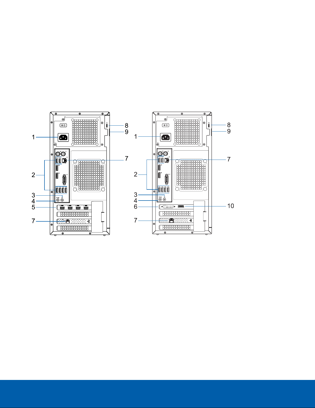
Back View
Figure 2: Rear view: (Left) 4 monitor remote monitoring workstation; (right) 2 monitor remote monitoring workstation.
1.
Power supply connector
Accepts power supply connection.
2.
USB connectors
Accepts USB connections to external devices.
3.
Headphone connector
Accepts a line-out audio connector.
4.
Microphone connector
Accepts a line-in audio connector.
5.
mDP connectors
Accepts a miniDisplayPort connection to a display monitor.
Back View 2
Page 7

6.
DVI connector
Accepts a DVI-D connection to a display monitor.
7.
1 Gigabit Ethernet ports
Accepts an Ethernet connection to the network.
8.
Security cable connector
Accepts a security cable to prevent theft.
9.
Padlock ring
Allows a padlock to secure the computer cover to the chasis.
10.
DisplayPort connector
Accepts a DisplayPort (DP) connection to a display monitor.
Back View 3
Page 8

Installation
Package Contents
Ensure the package contains the following:
l Avigilon 4 Monitor Remote Monitoring Workstation
o
Power cable
o
Keyboard and mouse
o
4 mDP to HDMI adapters
l Avigilon 2 Monitor Remote Monitoring Workstation
o
Power cable
o
Keyboard and mouse
o
1 DP to DVI adapter
o
2 DVI to HDMI adapters
Connecting Cables
Refer to the diagrams in the Overview section for the location of the different connectors. Make any of the
following connections as required:
1. Connect the keyboard and mouse to the USB connectors on the workstation.
2. Connect the monitors to the dedicated graphics processor on the workstation using one of the following
configurations:
Monitor
Connections for 2 Monitor Workstation Connections for 4 Monitor Workstation
ports
DP l Connect monitor 1 directly to DP
l Connect monitor 2 to monitor 1 in a daisy-
n/a
chain configuration
DVI l Connect monitor 1 directly to DVI port
l Connect monitor 2 to DP using DPto
n/a
DVIadapter
HDMI l Connect monitor 1 to DVI port using DVI
to HDMI adapter
l Connect monitor 2 to DP using both DP to
l Connect HDMImonitors to mDP
using mDP to HDMI adapters.
DVI and DVI to HDMI adapters
mDP n/a l Connect 4K monitors directly to
mDP
3. Connect the workstation to your network using an Ethernet network cable.
Installation 4
Page 9

4. Connect the power cable to the power supply at the back of the workstation.
5. It is recommended to connect a security cable and use a padlock to prevent theft of the workstation.
6. Press the power button on the front of the workstation.
The workstation turns on and loads the Windows operating system.
Configuring Windows 10
After the workstation starts, you will need to configure the Windows operating system for the first time.
1. On the first screen, the MICROSOFT SOFTWARE LICENSE TERMS is displayed. Review the terms and
click Accept.
2. Select Join Local Active Directory.
Note: This prompt will only appear if an Active Directory is present on the network, see the Windows
Help and Support files for more information.
3. Enter a user name for accessing the Windows software.
4. Set a password for the user name you entered on the previous screen. When you are ready, click Next.
5. The Avigilon End User License Agreement is displayed, Review the terms and click Accept.
Proceed to activate the license for the Avigilon Control Center software on your Remote Monitoring
Workstation.
Activating the Avigilon Control Center™ License
Downgrading to the ACC 5 Software:
The ACC 6 software is pre-installed on the Remote Monitoring Workstation .
You can use the ACC 6 software or the ACC 5 software.
Do not activate the ACC 6 software if you plan to use the ACC 5 software. See Downgrading to the ACC 5
Software on page7.
Before you can configure cameras and monitor live or recorded video, you will need to activate the ACC 6
software license provided with your device. If you don't have a license, you will need to purchase one.
Other parts of the ACC system may start while you perform this procedure, but you will not be able to use any of
the features until after license activation is complete.
Licensing the ACC™ 6 Software
The first time you connect to the new appliance with the ACC Client, you must activate a license for the new
ACC software. After the license is activated, you can immediately use the licensed features.
Configuring Windows 10 5
Page 10

1. Double-click the new name to log in. There is no user name or password set on the .
2.
In the top-left corner, click to open the New Task menu, then click .
3.
In the site Setup tab, click .
4. In the License Management dialog box, click Add License….
5. In the following dialog box, select one of the following tabs:
l If you have internet access, select the Automatic tab. Go to Automatic License Activation below.
l If you do not have internet access, or you plan to keep the system on a private intranet, select the
Manual tab. Go to Manual License Activation below.
Automatic License Activation
In the Automatic tab:
1. In the Enter Product Keys section, enter the license key.
2. In the Activate and License Site section, click Activate now.
Manual License Activation
In the Manual tab:
1. In the Enter Product Keys section, enter the license key.
2. In Generate Activation File section, click Save File….
3. In the Save As window, select where you want to save the .key file that is generated by the system. You
can rename the file as required.
4. Click Save.
5. Copy the .key file to a computer with internet access.
Open a web browser and go to http://activate.avigilon.com.
1. Click Choose File and select the .key file, click Upload. The generated license file (.lic) will download
automatically. If it does not, allow the download to occur when you are prompted.
2. Copy the downloaded .lic file to a location that would be accessible to the ACC Client software.
3. Complete the product registration page to receive product updates from Avigilon, then click Register.
Return to the ACC Client:
1. In the Apply License File section, click Apply….
2. Locate the downloaded .lic file and click Open.
3. In the Confirm Licenses dialog box, click OK.
Modifying Licenses
You can use the the License Management dialog box to add, remove, deactivate, and reactivate licenses for the
ACC 6 software. For more information, see the Avigilon Control Center Client User Guide.
Automatic License Activation 6
Page 11

Downgrading to the ACC 5 Software
1. Open Windows Settings > Apps > Features and uninstall the ACC 6 software.
2. In Windows explorer, open the D: drive and delete the following directories:
D:\AvigilonConfig
D:\AvigilonData
3. In Windows Explorer, go to C:\Avigilon\Control Center Installation Files\5.10.
4. Install each application by double-clicking the installers in the following order:
ACC 5 Server
ACC 5 Client
ACC 5 Player
ACC 5 Gateway
5. To activate your license, see the Avigilon Control Center Server User Guide for the ACC 5 software,
available on http://avigilon.com.
Troubleshooting Installation—Networking
By default, the Remote Monitoring Workstation acquires an IP address on the network through DHCP. If you
need to set up the workstation to use a static IP address or any specific network configuration, see the Windows
Help and Support files for more information.
Downgrading to the ACC 5 Software 7
Page 12

Configuring the Avigilon Control Center Software
Complete the following procedures to configure the ACC software to work with your newly installed device.
For more information about any of the following procedures, see the Help files provided with the ACC Client
software.
Starting Up and Shutting Down the ACC Client Software
After you install the ACC Client software, start the application and log in to the Remote Monitoring Workstation.
The ACC Client software should start automatically when your Windows workstation starts. Refer to the following
steps if it doesn't.
Starting Up the Client Software
Perform one of the following:
l In the Start menu, select All Programs or All Apps > Avigilon > Avigilon Control Center Client.
l
Double-click or desktop shortcut icon.
l From the AvigilonControl Center Admin Tool, click Launch Control Center Client. For more information,
see the AvigilonControl Center Server User Guide.
When you are prompted, log in to your site. You can only access cameras and video after you log in.
The “Select one or more sites to log in.” message appears. If you are connected only to the new device, one
site is listed in the left navigation panel. Otherwise, all the sites that are connected to the same network are
listed. The site name of your new device is the hostname that you assigned in the Web Interface. You can use
Find Site… to specify the IPaddress or hostname of the device if the list is long.
Shutting Down the Client Software
1.
In the top-right corner of the Client software, select > Exit.
2. When the confirmation dialog box appears, click Yes.
Logging In to and Out of a Site
After you start the ACC Client software, you are immediately asked to log in to a site.
The default username is administrator with no password.
Configuring the Avigilon Control Center Software 8
Page 13

Logging In
1. Open the Site Login tab. The Site Login tab is automatically displayed if you are launching the Client
software for the first time.
To manually access the Site Login tab, do one of the following:
l
From the top-right corner of the window, select > Log In….
l
From the top-left corner of the application window, click to open the New Task menu, then
click .
2. On the left side of the Site Login tab, select one or more sites.
If the site you want to log into is not shown, click Find Site… to discover the site.
3. Enter your username and password for the selected sites.
4. Click Log In.
5. If Two-Factor Authentication is required, a dialog box is displayed.
a. The first time you log in, a QRcode is displayed. On your mobile device, scan the QR code with a
TOTP authenticator app like the Google Authenticator™ mobile app or the FreeOTP Authenticator™
mobile app. If you cannot scan the QRcode, enter the 20-character key into the authenticator app.
The authenticator app will display a 6-character verification code.
b. The next time you log in, use the authenticator app to get your verification code.
c. Enter the code in the Verification Code: box.
Tip: Select the Trust this device for 30 days check box to avoid entering a verification code each
time you log in.
d. Click OK.
You are logged in to the selected sites.
If you want to be notified when new or disconnected sites come online, select the Notify me when additional
sites become available check box.
If you want to see the login page each time you launch the Client software, select the Show this tab on startup
check box. If you prefer not to login each time, you can disable this option and configure automatic login from
the Client Settings dialog box.
Logging Out
You can log out of one or all sites at any time.
To... Do this...
Log out of one or select sites l In the System Explorer, select one or more sites then right-click and
select Log Out.
Log out of all sites
1.
In the top-right corner of the Client, select > Log Out.
2. In the confirmation dialog box, click Yes.
Logging In 9
Page 14

Navigating the Client
Once you log in, the ACC Client application window is populated with all the features that are available to you.
NOTE: Some features are not availableif the server does not have the required license, or if you do not have
the required user permissions.
Figure 3: The Avigilon Control Center Client application window
Application Window Features
Area Description
1 System Explorer Displays all the elements in your surveillance system.
Use the Search… bar to quickly locate anything that is available in the
System Explorer. You can search for items by name, and devices can
also be searched for by location, logical ID, serial number and IP
address.
Tip: The content of the System Explorer changes depending on the
tab you have open. For example, servers are not listed in the View tab.
2 View tab Allows you to monitor video and organize image panels. You can have
multiple Views open at once.
Click to open a new View tab.
3 Image panel Displays live or recorded video from a camera. The video control
buttons are displayed when you move your mouse into the image
panel.
Navigating the Client 10
Page 15

Area Description
4 Toolbar Provides quick access to commonly used tools.
5 Task tabs Displays all the tabs that are currently open.
New Task menu Opens the New Task menu so you can select and open new task tabs.
You can access advanced tools like Search and Export, or system
administrative features like Site Setup.
The Application Menu
menu
System message list The highlighted number shows the number of system messages that
System Explorer Icons
Icon Description
A site. Listed under a site are all the connected devices and linked features in the system.
A virtual folder. Used to group and organize items in the View tab.
A server. Only visible from system administration tabs and dialogs.
A fixed camera.
This menu gives you access to local application settings like Client
Settings. You can also open a new window from this menu.
need your attention. Click the number to display the list of messages.
The highlight color indicates the severity of the most recent message.
l Red = Error
l Yellow = Warning
l Green = Information
A PTZ camera.
An AvigilonPresence Detector™ sensor.
An encoder.
An Access Control Manager (ACM) appliance. Only visible when an ACM™ appliance is connected to
a site.
An ACM panel.
An ACM subpanel.
An ACM input.
A saved View.
A map.
System Explorer Icons 11
Page 16

Icon Description
A web page.
Monitoring Video
Inside a View tab, you can monitor and control video from multiple cameras. Once you open a camera in a View
tab, you can control the camera's live and recorded video stream.
NOTE: Some features are not availableif the server does not have the required license, or if you do not have
the required user permissions.
Adding and Removing Cameras in a View
To monitor video, add a camera to a View tab. Camera video can be removed from a View tab at any time.
Adding a Camera to a View
Do one of the following:
l Drag the camera from the System Explorer to an empty image panel in the View tab.
l Double-click a camera in the System Explorer.
l In the System Explorer, right-click the camera and select Add To View.
l If your cameras are assigned a Logical ID:, press / and enter a logical id.
The camera is added to the next empty image panel in the View layout.
Tip: You can drag the same camera to multiple image panels to watch the video at different zoom levels.
Removing a Camera from a View
Do one of the following:
l Right-click the image panel and select Close.
l
Inside the image panel, click .
Viewing Live and Recorded Video
NOTE: Some features are not availableif the server does not have the required license, or if you do not have
the required user permissions.
Tip: If you cannot see either Live or Recorded on the toolbar, you may need Dual Authorization.
When you monitor video, you can choose to watch live and recorded video in the same View tab, or only one
type of video per View tab.
Once you've added cameras to the View tab, you can do the following:
Monitoring Video 12
Page 17

l
To switch all of the image panels in the View between live and recorded video, click either Live or
Recorded on the toolbar.
l To switch individual image panels between live and recorded video, right-click the image panel and
select either Live or Recorded.
Image panels displaying recorded video have a green border.
Zooming and Panning in a Video
Use the zoom and pan tools to focus on specific areas in the video stream.
Using the Zoom Tools
There are two ways to digitally zoom in and zoom out of a video image:
l Move your mouse over the video image, then rotate your mouse wheel forward and backward.
l
On the toolbar, select or , then click the image panel until you reach the desired zoom depth.
Using the Pan Tools
There are two ways to pan through the video image:
l Right-click and drag inside an image panel.
l
On the toolbar, select , then click and drag the video image in any direction inside the image panel.
Maximizing and Restoring an Image Panel
You can maximize an image panel to enlarge the video display.
Maximizing an Image Panel
Do one of the following:
l Right-click an image panel and select Maximize.
l
Inside the image panel, click .
l Double-click the image panel.
Restoring an Image Panel
In a maximized image panel, do one of the following:
l Right-click the maximized image panel and select Restore Down.
l
Inside the image panel, click .
l Double-click the image panel.
Playing Back Recorded Video
The Timeline displays when video was recorded and lets you control video playback. Recorded video may be
stored on the ACC Server or the archive storage location.
Zooming and Panning in a Video 13
Page 18

Figure 4: Playback con trols on the Timeline.
The colored bars on the Timeline show the camera's recording history:
l
l
l
l White areas show that there is no recorded video.
— shows the camera has recorded a motion event.
— shows the camera has recorded video.
— is a bookmark of a recorded event.
To... Do this...
Select a playback
time
l Click the dark gray date display and select a specific date and time.
l Click a point on the Timeline.
Start playback
Click .
l
Click to fast forward. Tap the arrow again to increase the playback speed.
l
Click to rewind. Tap the arrow again to increase the playback speed.
You can play the video up to eight times the original speed.
Stop playback
Click .
l
Click to step forward one frame.
l
Click to step backward one frame.
Jump forward or
backward on the
On the Timeline, click or to move to set points on
the Timeline.
Timeline
Zoom in or out of the
Timeline
l Move the slider on the bottom left to zoom in or
out on the Timeline.
l Place your mouse over the Timeline and use the
scroll wheel to zoom in or out on the Timeline.
You can zoom in to a quarter of a second, and zoom out
Playing Back Recorded Video 14
Page 19

To... Do this...
to see years if recorded video exists.
Center the Timeline
Right-click the Timeline, and select Center on Marker.
on the time marker
Pan the Timeline l Click and drag the time marker through the
Timeline.
l Move the horizontal scroll bar under theTimeline.
l Right-click and drag the Timeline.
Adding Bookmarks to Recorded Video
Bookmarks can be added to recorded video to help you find and review an event at a later time.
Tip: You can add a bookmark any time the Timeline is displayed.
1. Drag the time marker to where you want to start the bookmark, then right-click the Timeline and select
Add Bookmark.
The Edit Bookmark dialog box appears, and the bookmark time range is highlighted on the Timeline.
2. Enter a name for the New Bookmark.
3. In the Cameras: pane, select all the cameras that need to be attached to this bookmark.
NOTE: You can only bookmark multiple cameras from the same site.
4. In the Time Range to Bookmark: area, enter the full duration of the bookmark.
You can also move the black time range markers on the Timeline to adjust the time range.
5. In the Description: field, enter any extra information that you want to include with the bookmark.
6. To protect the bookmark video from being deleted, select the Protect bookmark data check box.
NOTE: Protected bookmarks are never deleted. Be aware that bookmarked videos take up space and
can become the oldest video on the server.
7. To make the bookmark private, select the Bookmark is private check box. Private bookmarks are only
visible to the user who marked the bookmark as private, and the system administrator. No one else will
have access to the bookmark.
8. Click OK.
A bookmark has been created.
Advanced Features
The following list provides some advanced features you can use to improve your monitoring experience. See
the application Help files for details about how to use each feature.
Adding Bookmarks to Recorded Video 15
Page 20

NOTE: Some features are not availableif the server does not have the required license, or if you do not have
the required user permissions.
l PTZ controls
l If you have a PTZ camera, you can use the Pan, Tilt, Zoom (PTZ) controls to focus on specific areas
in the video stream.
l You can set up PTZtours to allow the PTZ camera to automatically move between a series of
preset positions. The PTZ camera can pause at each preset position for a specific amount of time
for video monitoring.
l Search
l You can quickly search your recorded video for specific events that the system is configured to
identify.
l If you have a self-learning video analytics camera in your system, motion search can be used to
search recorded video for classified objects such as persons or vehicles.
l If you do have an analytics camera, motion search can be used to search for tiny pixel changes in
the camera's field of view.
l Thumbnail search can be used to do a visual search of the search results which are a series of
thumbnail images.
l Bookmark search allows you to search through all the listed bookmarks for a specific bookmark.
l Export
l Recorded video can be exported to multiple video and image formats.
l Native video export maintains the original video compression and metadata so you can search the
exported video. It can be played with the ACC Player software.
l Recorded video can also be exported as an AVIvideo or still image.
l Keyboard commands
l You can use keyboard commands to help you navigate the ACC Client software.
Advanced Features 16
Page 21

LED Indicators
The following table describes what the LEDs on the workstation indicate. For more information on the location of
the indicators, see Overview on page1.
Power Status Indicator
The power button indicator on the front of the workstation provides power and system state information. The
following table describes what the power button LED indicates:
LED Indicator Description
Off Power supply is not connected or the workstation is off.
Flashing white Power is being supplied and the workstation is in sleep state.
Flashing green There is a known problem with the power supply unit.
Steady green There is an unknown problem with the power supply unit.
Steady white The power supply unit is working and the workstation is powered on.
Hard Drive Activity Indicator
The hard drive activity indicator on the front of the workstation functions to provide information on the status of
the hard drive. The following table describes what the hard drive activity LED indicates:
LED Indicator Description
Off Hard drive is not being used.
Flashing white Data is being read or written.
Limited Warranty and Technical Support
Avigilon warranty terms for this product are provided at avigilon.com/warranty.
Warranty service and technical support can be obtained by contacting Avigilon Technical Support:
avigilon.com/contact-us/.
LEDIndicators 17
 Loading...