

Page 1

User Guide
Avigilon™ Remote Monitoring Workstation
HD-RMWS3-4MN and HD-RMWS3-2MN
Page 2

Copyright
©2017,Avigilon Corporation. All rights reserved. AVIGILON, the AVIGILON logo, AVIGILON CONTROL CENTER,
ACC and TRUSTED SECURITY SOLUTIONS are trademarks of Avigilon Corporation. Other names mentioned
herein may be the trademarks of their respective owners. The absence of the symbols ™ and ® in proximity to
each trademark in this document is not a disclaimer of ownership of the related trademark. Avigilon Corporation
protects its innovations with patents issued in the United States of America and other jurisdictions worldwide:
avigilon.com/patents. Unless stated explicitly and in writing, no license is granted with respect to any copyright,
industrial design, trademark, patent or other intellectual property rights of Avigilon Corporation or its licensors.
This document has been compiled and published covering the latest product descriptions and specifications.
The contents of this document and the specifications of the products discussed herein are subject to change
without notice. Avigilon Corporation reserves the right to make any such changes without notice. Neither
Avigilon Corporation nor any of its affiliated companies: (1) guarantees the completeness or accuracy of the
information contained in this document; or (2) is responsible for your use of, or reliance on, the information.
Avigilon Corporation shall not be responsible for any losses or damages (including consequential damages)
caused by reliance on the information presented herein.
Avigilon Corporation
avigilon.com
PDF-RMWS3-B
Revision: 1 - EN
20170308
2
Page 3

Table of Contents
Introduction 1
Overview 1
Front View 1
Back View 2
Installation 4
Package Contents 4
Connecting Cables 4
Logging into Windows for the First Time 5
Networking 6
Using the Avigilon Control Center Client Software 7
Starting Up and Shutting Down the Avigilon Control Center Client Software 7
Starting Up the Client Software 7
Shutting Down the Client Software 7
Logging Into and Out of a Site 7
Logging In 8
Logging Out 8
Navigating the Client 8
Application Window Features 9
System Explorer Icons 10
Monitoring Video 10
Adding and Removing Cameras in a View 10
Adding a Camera to a View 10
Removing a Camera from a View 10
Viewing Live and Recorded Video 11
Maximizing and Restoring an Image Panel 11
Maximizing an Image Panel 11
Restoring an Image Panel 11
Zooming and Panning in a Video 11
Using the Zoom Tools 11
Using the Pan Tools 11
Playing Back Recorded Video 12
Adding Bookmarks to Recorded Video 13
Advanced Features 13
LED Indicators 15
Power Status Indicator 15
3
Page 4

Hard Drive Activity Indicator 15
Specifications 16
Limited Warranty and Technical Support 17
4
Page 5
Introduction
The Avigilon Remote Monitoring Workstation is preloaded with Avigilon Control Center™ (ACC) Client software
and is configured for exceptional performance and reliability. The Remote Monitoring Workstation can be easily
integrated into any existing NVR products or Avigilon surveillance systems to add an additional monitoring
station.
Overview
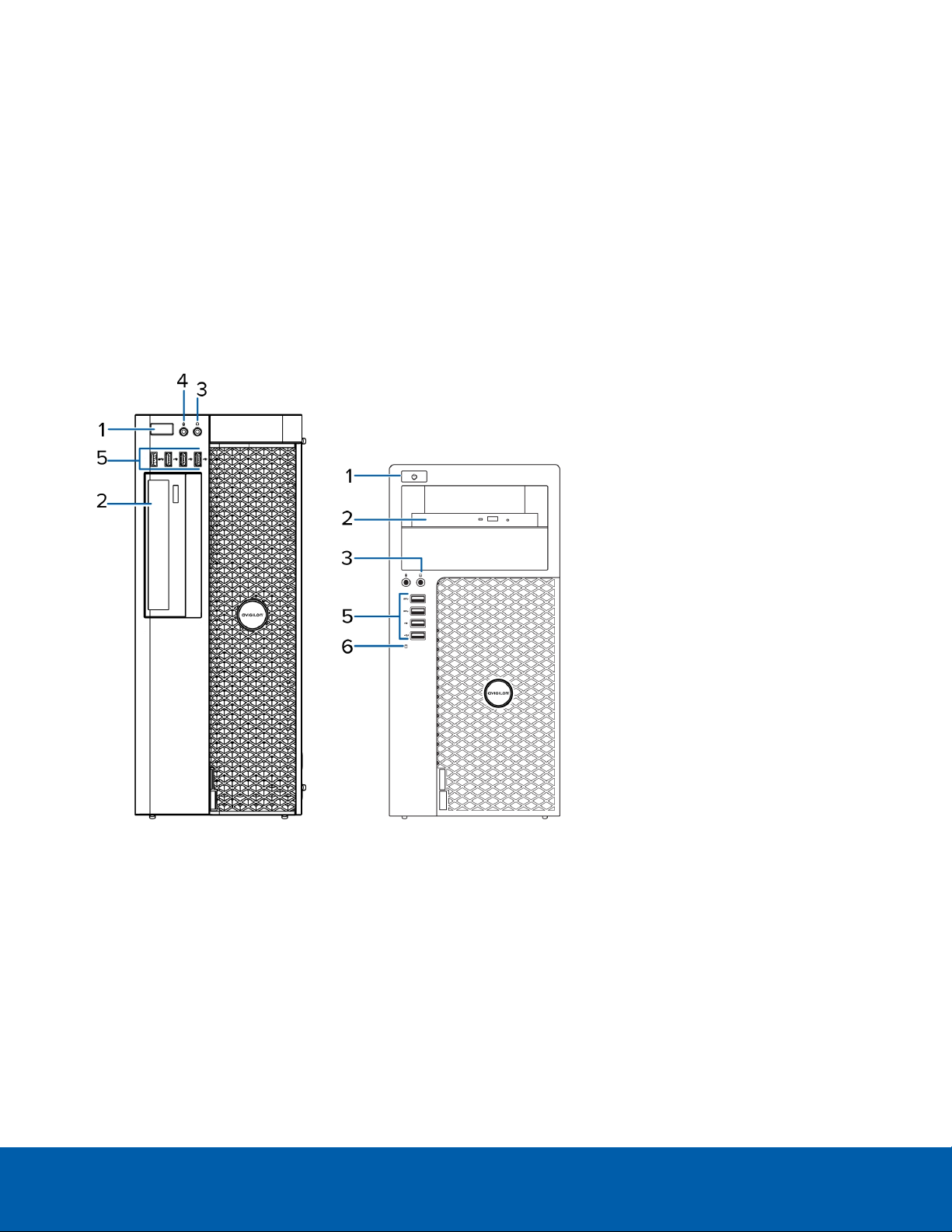
Front View
Figure 1: (Left) 4 monitor remote monitoring workstation; (right) 2 monitor remote monitoring workstation.
1.
Power button
Controls the power supply to the workstation. For more information, see Power Status Indicator on
page15.
2.
Optical drive
Accepts a CD or DVD.
3.
Headphone connector
Accepts a line-out audio connector.
Introduction 1
Page 6
4.
Microphone connector
Accepts a line-in audio connector.
5.
USB connectors
Accepts USB connections to external devices.
6.
Hard drive activity indicator
Provides information about hard-drive activity. For more information, see Hard Drive Activity Indicator on
page15.
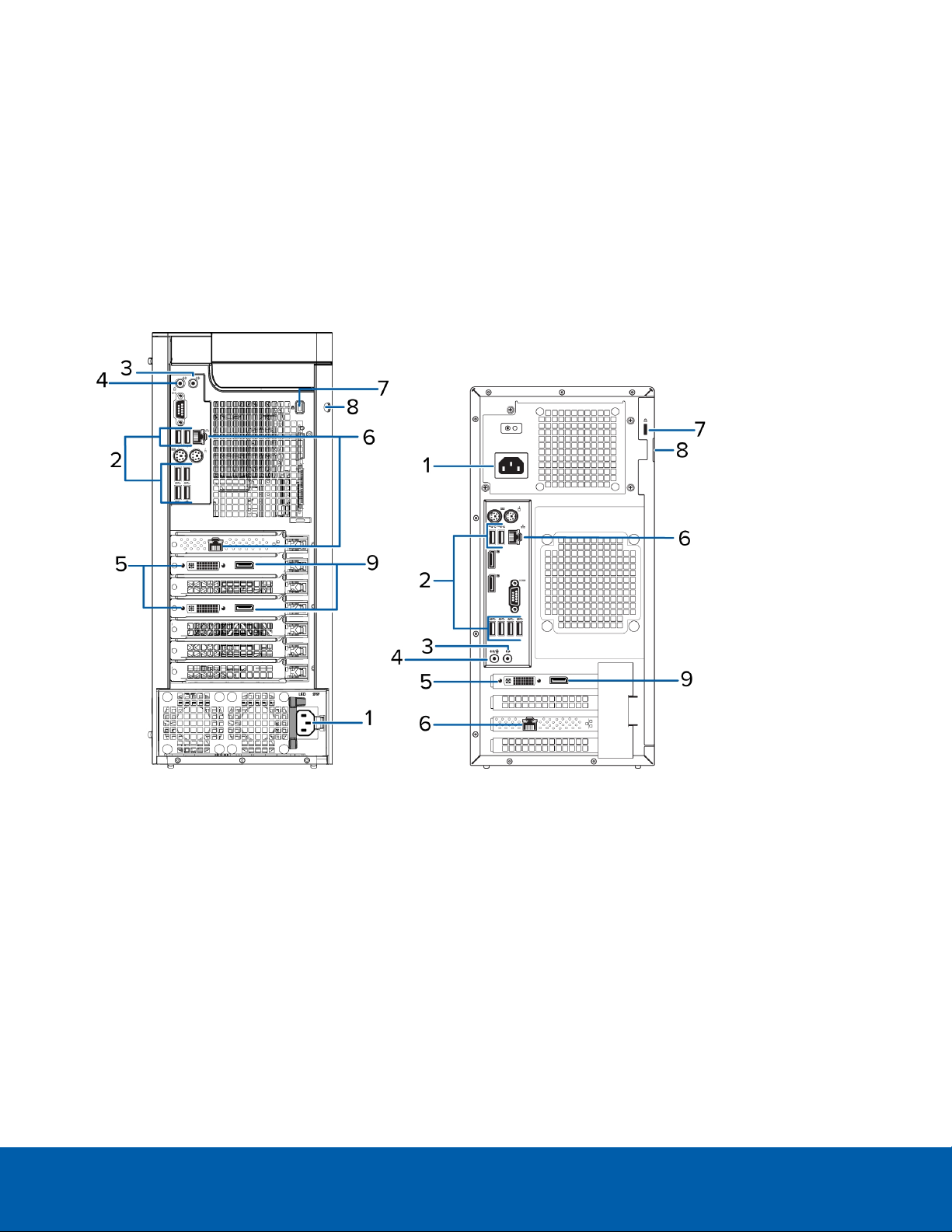
Back View
Figure 2: (Left) 4 monitor remote monitoring workstation; (right) 2 monitor remote monitoring workstation.
1.
Power supply connector
Accepts power supply connection.
2.
USB connectors
Accepts USB connections to external devices.
3.
Headphone connector
Accepts a line-out audio connector.
4.
Microphone connector
Accepts a line-in audio connector.
Back View 2
Page 7

5.
DVI connector
Accepts a DVI-D connection to a display monitor.
6.
1 Gigabit Ethernet ports
Accepts an Ethernet connection to the network.
7.
Security cable connector
Accepts a security cable to prevent theft.
8.
Padlock ring
Allows a padlock to secure the computer cover to the chasis.
9.
DisplayPort connector
Accepts a DisplayPort (DP) connection to a display monitor.
Back View 3
Page 8

Installation
Package Contents
Ensure the package contains the following:
l Avigilon 4 Monitor Remote Monitoring Workstation
o
Power cable
o
Keyboard and mouse
o
2 DP toDVI adapter
o
4 DVI to HDMI adapters
o
Recovery USB — contains a copy of the Avigilon Control Center Client software and the Windows
recovery software.
l Avigilon 2 Monitor Remote Monitoring Workstation
o
Power cable
o
Keyboard and mouse
o
1 DP to DVI adapter
o
2 DVI to HDMI adapters
o
Recovery USB — contains a copy of the Avigilon Control Center Client software and the Windows
recovery software.
Connecting Cables
Refer to the diagrams in the Overview section for the location of the different connectors. Make any of the
following connections as required:
Installation 4
Page 9

1. Connect the keyboard and mouse to the USB connectors on the workstation.
2. Connect the monitors to the dedicated graphics processor on the workstation using one of the following
configurations:
Monitor
ports
DP
DVI
Connections for 2 Monitor Workstation Connections for 4 Monitor Workstation
l Connect monitor 1 directly to DP
l Connect monitor 2 to monitor 1 in a
daisy-chain configuration
l Connect monitor 1 directly to DVI port
l Connect monitor 2 to DP using DPto
DVIadapter
l Connect monitor 1 to DVI port using
DVI to HDMI adapter
l Connect monitor 1 & 2 directly to DP
l Connect monitor 3 & 4 to the first two
monitors in a daisy-chain configuration
l Connect monitor 1 & 2 directly to DVI
port
l Connect monitor 3 & 4 to DP using DPto
DVIadapter
l Connect monitor 1 & 2 to DVI port using
DVI to HDMI adapter
HDMI
l Connect monitor 2 to DP using both
DP to DVI and DVI to HDMI adapters
l Connect monitor 3 & 4 to DP using both
DP to DVI and DVI to HDMI adapters
3. Connect the workstation to your network using an Ethernet network cable.
4. Connect the power cable to the power supply at the back of the workstation.
5. It is recommended to connect a security cable and use a padlock to prevent theft of the workstation.
6. Press the power button on the front of the workstation.
The workstation turns on and loads the Windows operating system.
Logging into Windows for the First Time
When you start the Remote Monitoring Workstation for the first time, you will need to configure the Windows
operating system.
1. On the first screen, select your preferred system language then click Next.
2. Enter a username and computer name then click Next.
3. Set a password for the local administrator account then click Next.
4. Review the license terms for the Windows operating system then select the I accept the license terms
check box.
5. Click Next.
6. Set the workstation time zone, date, and time then click Next.
7. Select Work network as your computer's current network location.
Windows will apply all your settings then restart automatically.
Logging into Windows for the First Time 5
Page 10

Networking
By default, the Remote Monitoring Workstation acquires an IP address on the network through DHCP. If you
need to set up the workstation to use a static IP address or any specific network configuration, see the Windows
Help and Support files for more information.
Networking 6
Page 11

Using the Avigilon Control Center Client Software
After you set up the Remote Monitoring Workstation, the ACC system is ready to be used.
For more information about any of the following procedures, see the help files provided with the ACC Client
software.
Starting Up and Shutting Down the Avigilon Control Center Client Software 7
Logging Into and Out of a Site 7
Navigating the Client 8
Monitoring Video 10
Advanced Features 13
Starting Up and Shutting Down the Avigilon Control Center Client Software
The ACC Client software should start automatically when Windows starts. Refer to the following steps if it
doesn't.
Starting Up the Client Software
Perform one of the following:
l In the Start menu, select All Programs or All Apps > Avigilon > Avigilon Control Center Client.
l
Double-click or desktop shortcut icon.
When you are prompted, log in to your site. You can only access cameras and video after you log in.
Once the application has started, it will automatically display a list of all the sites that are connected to the same
network. You will be prompted to log in to all sites.
Shutting Down the Client Software
1.
In the top-right corner of the Client software, select > Exit.
2. When the confirmation dialog box appears, click Yes.
Logging Into and Out of a Site
After you start the Client software, you are immediately asked to log in to a site.
Usingthe Avigilon Control Center Client Software 7
Page 12

Logging In
1. Open the Site Login tab. The Site Login tab is automatically displayed if you are launching the Client
software for the first time.
To manually access the Site Login tab, do one of the following:
l
From the top-right corner of the window, select > Log In....
l
From the top-left corner of the application window, click to open the New Task menu, then
click .
2. On the left side of the Site Login tab, select one or more sites.
If the site you want to log into is not shown, click Find Site... to discover the site.
3. Enter your username and password for the selected sites.
4. Click Log In.
You are logged into the selected sites.
If you want to be notified when new or disconnected sites come online, select the Notify me when additional
sites become available check box.
If you want to see the login page each time you launch the Client software, select the Show this tab on startup
check box. If you prefer not to login each time, you can disable this option and configure automatic login from
the Client Settings dialog box.
Logging Out
You can log out of one or all sites at any time.
To... Do this...
Log out of one or select sites
Log out of all sites
l In the System Explorer, select one or more sites then right-click and
select Log Out.
1.
In the top-right corner of the Client, select > Log Out.
2. In the confirmation dialog box, click Yes.
Navigating the Client
Once you log in, the ACC Client application window is populated with all the features that are available to you.
NOTE: Some features are not displayedif the server does not have the required license, or if you do not have
the required user permissions.
Logging I n 8
Page 13

Figure 3: The Avigilon Control Cen ter Client application window
Application Window Features
Area Description
Displays all the elements in your surveillance system.
Use the Search... bar to quickly locate anything that is available in the
System Explorer. You can search for items by name, and devices can
1 System Explorer
2 View tab
3 Image panel
4 Toolbar Provides quick access to commonly used tools.
also be searched for by location, logical ID, serial number and IP
address.
Tip: The content of the System Explorer changes depending on the tab
you have open. For example, servers are not listed in the View tab.
Allows you to monitor video and organize image panels. You can have
multiple Views open at once.
Click to open a new View tab.
Displays live or recorded video from a camera. The video control
buttons are displayed when you move your mouse into the image
panel.
5 Task tabs Displays all the tabs that are currently open.
Opens the New Task menu so you can select and open new task tabs.
New Task menu
You can access advanced tools like Search and Export, or system
administrative features like Site Setup.
The Application Menu
menu
Application Window Features 9
This menu gives you access to local application settings like Client
Settings. You can also open a new window from this menu.
Page 14

Area Description
The highlighted number shows the number of system messages that
need your attention. Click the number to display the list of messages.
The highlight color indicates the severity of the most recent message.
System message list
l Red = Error
l Yellow = Warning
l Green = Information
System Explorer Icons
Icon Description
A site. Listed under a site are all the connected devices and linked features in the system.
A virtual folder. Used to group and organize items in the View tab.
A server. Only visible from system administration tabs and dialogs.
A fixed camera.
A PTZ camera.
An encoder.
Monitoring Video
Inside a View tab, you can monitor and control video from multiple cameras. Once you open a camera in a View
tab, you can control the camera's live and recorded video stream.
NOTE: Some features are not displayedif the server does not have the required license, or if you do not have
the required user permissions.
Adding and Removing Cameras in a View
To monitor video, add a camera to a View tab. Camera video can be removed from a View tab at any time.
Adding a Camera to a View
Do one of the following:
l Drag the camera from the System Explorer to an empty image panel in the View tab.
l Double-click a camera in the System Explorer.
l In the System Explorer, right-click the camera and select Add To View.
The camera is added to the next empty image panel in the View layout.
Tip: You can drag the same camera to multiple image panels to watch the video at different zoom levels.
Removing a Camera from a View
Do one of the following:
System Explorer Icons 10
Page 15

l Right-click the image panel and select Close.
l
Inside the image panel, click .
Viewing Live and Recorded Video
When you monitor video, you can choose to watch live and recorded video in the same View tab, or only one
type of video per View tab.
Once you've added cameras to the View tab, you can do the following:
l To switch all of the image panels in the View between live and recorded video, click either Live or
Recorded on the toolbar.
l To switch individual image panels between live and recorded video, right-click the image panel and
select either Live or Recorded.
Maximizing and Restoring an Image Panel
You can maximize an image panel to enlarge the video display.
Maximizing an Image Panel
Do one of the following:
l Right-click an image panel and select Maximize.
l
Inside the image panel, click .
l Double-click the image panel.
Restoring an Image Panel
In a maximized image panel, do one of the following:
l Right-click the maximized image panel and select Restore Down.
l
Inside the image panel, click .
l Double-click the image panel.
Zooming and Panning in a Video
Use the zoom and pan tools to focus on specific areas in the video stream.
Using the Zoom Tools
There are two ways to digitally zoom in and zoom out of a video image:
l Move your mouse over the video image, then rotate your mouse wheel forward and backward.
Using the Pan Tools
There are two ways to pan through the video image:
l Right-click and drag inside an image panel.
l
On the toolbar, select , then click and drag the video image in any direction inside the image panel.
Viewing Live and Recorded Video 11
Page 16

Playing Back Recorded Video
NOTE: If the recorded video playback is slow, there may be a network issue between the Client software and
the site. Actual recorded video quality is not affected.
The Timeline displays when video was recorded and lets you control video playback.
The colored bars on the Timeline show the camera's recording history:
l A red bar shows the camera has recorded a motion event.
l A blue bar shows the camera has recorded video.
l White areas show when the camera has not recorded any video.
l A yellow bar is a bookmark in the camera's recording history.
Figure 4: Playback con trols on th e Timeline.
To... Do this...
Select a playback
time
Start playback
Stop playback
Jump forward or
backward on the
Timeline
l Click the dark gray date display and select a specific date and time.
l Click a point on the Timeline.
Click .
l
Click to fast forward. Tap the arrow again to increase the playback speed.
l
Click to rewind. Tap the arrow again to increase the playback speed.
You can play the video up to eight times the original speed.
Click .
l
Click to step forward one frame.
l
Click to step backward one frame.
On the Timeline, click or to move to set points on the
Timeline.
l Move the slider on the bottom left to zoom in or out
Zoom in or out of the
on the Timeline.
Timeline
l Place your mouse over the Timeline and use the
Playing BackRecorded Video 12
Page 17

To... Do this...
scroll wheel to zoom in or out on the Timeline.
You can zoom in to a quarter of a second, and zoom out to
see years if recorded video exists.
Center the Timeline
on the time marker
Right-click the Timeline, and select Center on Marker.
l Click and drag the time marker through the
Timeline.
Pan the Timeline
l Move the horizontal scroll bar under theTimeline.
l Right-click and drag the Timeline.
Adding Bookmarks to Recorded Video
Bookmarks can be added to recorded video to help you find and review an event at a later time.
Tip: You can add a bookmark any time the Timeline is displayed.
1. Drag the time marker to where you want to start the bookmark, then right-click the Timeline and select
Add Bookmark.
The Edit Bookmark dialog box appears, and the bookmark time range is highlighted on the Timeline.
2. Enter a name for the New Bookmark.
3. In the Cameras: pane, select all the cameras that need to be attached to this bookmark.
NOTE: You can only bookmark multiple cameras from the same site.
4. In the Time Range to Bookmark: area, enter the full duration of the bookmark.
You can also move the black time range markers on the Timeline to adjust the time range.
5. In the Description: field, enter any extra information that you want to include with the bookmark.
6. To protect the bookmark video from being deleted, select the Protect bookmark data check box.
NOTE: Protected bookmarks are never deleted. Be aware that bookmarked videos take up space and
can become the oldest video on the server.
7. Click OK.
A bookmark has been created.
Advanced Features
The following list provides some advanced features you can use to improve your monitoring experience. See
the application Help files for details about how to use each feature.
NOTE: Some features are not displayedif the server does not have the required license, or if you do not have
the required user permissions.
Adding Bookmarks to Recorded Video 13
Page 18

l PTZ controls
l If you have a PTZ camera, you can use the Pan, Tilt, Zoom (PTZ) controls to focus on specific areas
in the video stream.
l You can set up PTZtours to allow the PTZ camera to automatically move between a series of
preset positions. The PTZ camera can pause at each preset position for a specific amount of time
for video monitoring.
l Search
l You can quickly search your recorded video for specific events that the system is configured to
identify.
l If you have a self-learning video analytics camera in your system, motion search can be used to
search recorded video for classified objects such as persons or vehicles.
l If you do have an analytics camera, motion search can be used to search for tiny pixel changes in
the camera's field of view.
l Thumbnail search can be used to do a visual search of the search results which are a series of
thumbnail images.
l Bookmark search allows you to search through all the listed bookmarks for a specific bookmark.
l Export
l Recorded video can be exported to multiple video and image formats.
l Native video export maintains the original video compression and metadata so you can search the
exported video. It can be played with the ACC Player software.
l Recorded video can also be exported as an AVIvideo or still image.
l Keyboard commands
l You can use keyboard commands to help you navigate the ACC Client software.
Advanced Features 14
Page 19

LED Indicators
The following table describes what the LEDs on the workstation indicate. For more information on the location of
the indicators, see Overview on page1.
Power Status Indicator
The power button indicator on the front of the workstation functions to provide power and system state
information. The following table describes what the power button LED indicates:
LED Indicator Description
Off Power supply is not connected or the workstation is off.
Flashing white Power is being supplied and the workstation is in sleep state.
Flashing green There is a known problem with the power supply unit.
Steady green There is an unknown problem with the power supply unit.
Steady white The power supply unit is working and the workstation is powered on.
Hard Drive Activity Indicator
The hard drive activity indicator on the front of the workstation functions to provide information on the status of
the hard drive. The following table describes what the hard drive activity LED indicates:
LED Indicator Description
Off Hard drive is not being used.
Flashing white Data is being read or written.
LEDIndicators 15
Page 20

Specifications
System
Operating System Windows Embedded Standard 7
Hard DiskDrive Configuration 1—500GB OSHDD
Mechanical
HD-RMWS3-4MN — 172.6 mm x 416.9 mm x 471 mm (6.79 in x 16.41
in x 18.54 in)
Dimensions (H x W x D)
HD-RMWS3-2MN — 175 mm x 360 mm x 435 mm (6.89 in. x 14.17 in.
x 17.12 in.)
HD-RMWS3-4MN — 13.50 kg (29.80 lb)
Weight
HD-RMWS3-2MN — 9.24 kg (20.35 lbs)
Form Factor Desktop
Electrical
Power Input 100 to 240 VAC, 50/60 Hz, auto-switching
HD-RMWS3-4MN — 685 W
Power Consumption
HD-RMWS3-2MN — 290 W
Power Supply Single non-redundant
Environmental
HD-RMWS3-4MN — 10 °C to 35 °C (50 °F to 95 °F)
Operating Temperature
HD-RMWS3-2MN — 5° C to 35° C (41° F to 95° F)
Storage Temperature -40°C to 65°C (-40°F to 149°F)
Humidity 20% to 80% relative humidity (non-condensing)
Operating Vibration 0.26 GRMS
Storage Vibration 2.20 GRMS
Operating Shock 40G
Storage Shock 105 G
Operating Altitude -15.2 m to 3,048 m (-50 ft to 10,000 ft)
Storage Altitude -15.2 m to 10,668 m (-50 ft to 35,000 ft)
Certifications
Certifications UL, cUL, CE, RCM, CCC, EAC, VCCI, KC, BSMI, NRCS
Directives RoHS, SVHC
Specifications 16
Page 21

Limited Warranty and Technical Support
Avigilon warranty terms for this product is provided at avigilon.com/warranty.
Warranty service and technical support can be obtained by contacting Avigilon Technical Support:
avigilon.com/contact-us/.
Limited Warranty and Technical Support 17
 Loading...