

Page 1

User Guide
Avigilon™ Network Video Recorder Workstation
HD-NVRWS3-8TB
Page 2

Copyright
©2017,Avigilon Corporation. All rights reserved. AVIGILON, the AVIGILON logo, AVIGILON CONTROL CENTER,
ACC and TRUSTED SECURITY SOLUTIONS are trademarks of Avigilon Corporation. Other names mentioned
herein may be the trademarks of their respective owners. The absence of the symbols ™ and ® in proximity to
each trademark in this document is not a disclaimer of ownership of the related trademark. Avigilon Corporation
protects its innovations with patents issued in the United States of America and other jurisdictions worldwide:
avigilon.com/patents. Unless stated explicitly and in writing, no license is granted with respect to any copyright,
industrial design, trademark, patent or other intellectual property rights of Avigilon Corporation or its licensors.
This document has been compiled and published covering the latest product descriptions and specifications.
The contents of this document and the specifications of the products discussed herein are subject to change
without notice. Avigilon Corporation reserves the right to make any such changes without notice. Neither
Avigilon Corporation nor any of its affiliated companies: (1) guarantees the completeness or accuracy of the
information contained in this document; or (2) is responsible for your use of, or reliance on, the information.
Avigilon Corporation shall not be responsible for any losses or damages (including consequential damages)
caused by reliance on the information presented herein.
Avigilon Corporation
avigilon.com
PDF-NVRWS3-A
Revision: 1 - EN
20170308
ii
Page 3

Table of Contents
Introduction 1
Overview 1
Front View 1
Back View 2
Installation 4
Package Contents 4
Connecting Cables 4
Logging into Windows for the First Time 4
Licensing the Avigilon Control Center (ACC)™ System 5
Internet Activation 5
Manual Activation 6
Adding Licenses 6
Networking 7
Configuring the Avigilon Control Center Software 8
Starting Up and Shutting Down the Avigilon Control Center Client Software 8
Starting Up the Client Software 8
Shutting Down the Client Software 8
Logging Into and Out of a Site 9
Logging In 9
Logging Out 9
Changing the Administrator Password 9
Connecting Cameras to the Avigilon Control Center System 10
Setting the Recording Schedule 11
Creating a Recording Template 11
Setting Up a Weekly Recording Schedule 12
Setting Data Aging 12
Adding Users and Groups 13
Adding Groups 14
Adding Users 14
Advanced Settings 15
LED Indicators 16
Power Status Indicator 16
Hard Drive Activity Indicator 16
Specifications 17
Limited Warranty and Technical Support 18
iii
Page 4
Introduction
The Avigilon™Network Video Recorder (NVR) Workstation is preloaded with Avigilon Control Center™ (ACC)
software and is configured for exceptional performance and reliability. The NVRWorkstation can be easily
integrated into any existing Avigilon surveillance system, or act as the base of a new site.
Overview
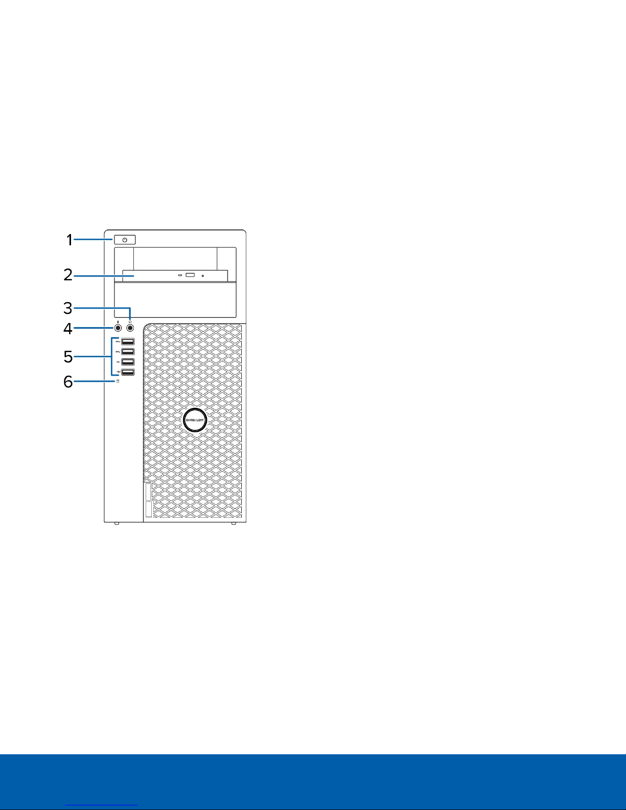
Front View
1.
Power button
Controls the power supply to the recorder. For more information, see Power Status Indicator on page16.
2.
Optical drive
Accepts a CD or DVD.
3.
Headphone connector
Accepts a line-out audio connector.
4.
Microphone connector
Accepts a line-in audio connector.
5.
USB connectors
Accepts USB connections to external devices.
Introduction 1
Page 5
6.
Hard drive activity indicator
Provides information about hard-drive activity. For more information, see Hard Drive Activity Indicator on
page16.
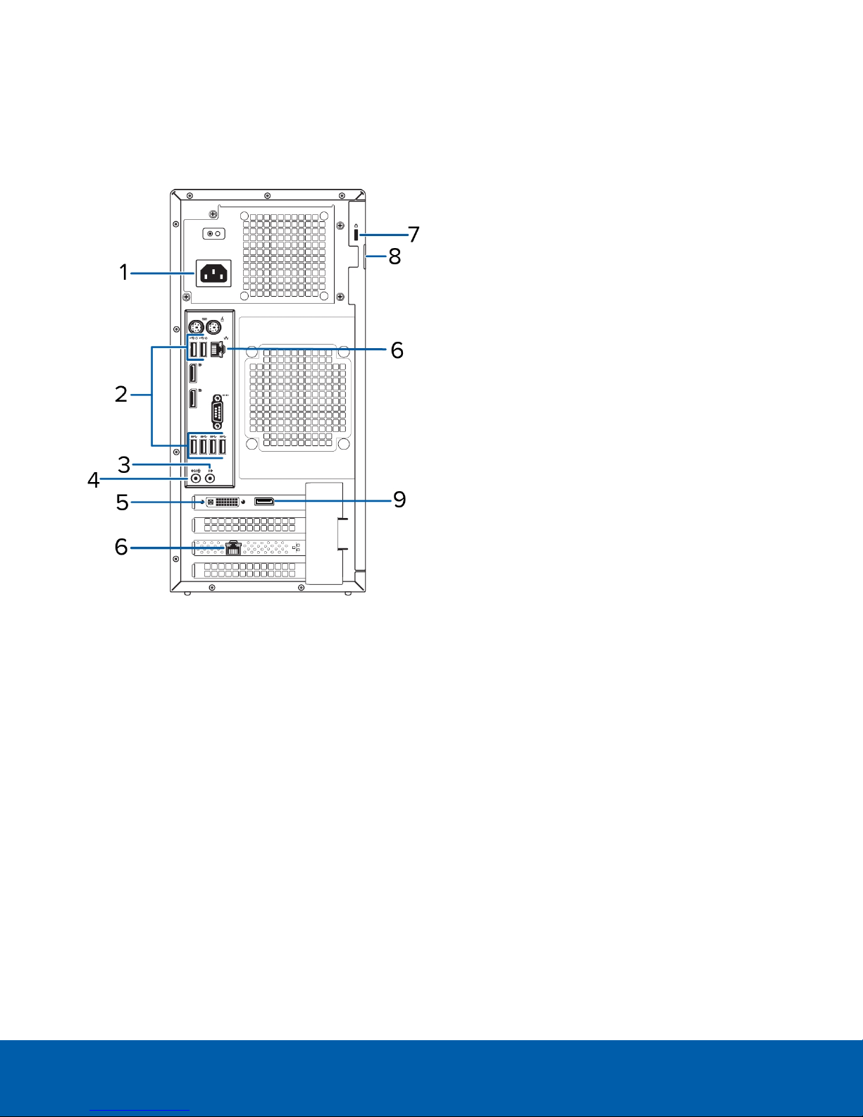
Back View
1.
Power supply connector
Accepts power supply connection.
2.
USB connectors
Accepts USB connections to external devices.
3.
Headphone connector
Accepts a line-out audio connector.
4.
Microphone connector
Accepts a line-in audio connector.
5.
DVI connector
Accepts a DVI-D connection to a display monitor.
6.
1 Gigabit Ethernet ports
Accepts an Ethernet connection to the network.
7.
Security cable connector
Accepts a security cable to prevent theft.
Back View 2
Page 6

8.
Padlock ring
Allows a padlock to secure the computer cover to the chasis.
9.
DisplayPort connector
Accepts a DisplayPort (DP) connection to a display monitor.
Back View 3
Page 7

Installation
Package Contents
Ensure the package contains the following:
l Avigilon NVRWorkstation
o
Power cable
o
Keyboard and mouse
o
1 DP to DVI adapter
o
2 DVI to HDMI adapters
o
Recovery USB — contains a copy of the Avigilon Control Center Client software and the Windows
recovery software.
Connecting Cables
Refer to the diagrams in the Overview section for the location of the different connectors. Make any of the
following connections as required:
1. Connect the keyboard and mouse to the USB connectors on the recorder.
2. Connect the monitors to the dedicated graphics processor on the recorder using one of the following
configurations:
Monitor ports Connections
DP
l Connect monitor 1 directly to DP
l Connect monitor 2 to monitor 1 in a daisy-chain configuration
l Connect monitor 1 directly to DVI port
DVI
l Connect monitor 2 to DP using DPto DVIadapter
l Connect monitor 1 to DVI port using DVI to HDMI adapter
HDMI
l Connect monitor 2 to DP using both DP to DVI and DVI to HDMI adapters
3. Connect the recorder to your network using an Ethernet network cable.
4. Connect the power cable to the power supply at the back of the recorder.
5. It is recommended to connect a security cable and use a padlock to prevent theft of the recorder.
6. Press the power button on the front of the recorder.
The NVRWorkstation turns on and loads the Windows operating system.
Logging into Windows for the First Time
When you start the NVRWorkstation for the first time, you will need to configure the Windows operating system.
Installation 4
Page 8

1. On the first screen, select your preferred system language then click Next.
2. Enter a username and computer name then click Next.
3. Set a password for the local administrator account then click Next.
4. Review the license terms for the Windows operating system then select the I accept the license terms
check box.
5. Click Next.
6. Set the NVRWorkstation time zone, date, and time then click Next.
7. Select Work network as your computer's current network location.
Windows will apply all your settings then restart automatically. After restarting, you will need to license
your Avigilon Control Center system.
Licensing the Avigilon Control Center (ACC)™ System
Before you can configure cameras and monitor live or recorded video, you will need to activate your ACC
software license. You will need to purchase a license if you don't already have one.
After the recorder restarts, the first screen you see is the Avigilon Control Center software license wizard.
Other parts of the ACC system may start while you perform this procedure, but you will not be able to use any of
the features until after license activation is complete.
1. Click License Activation.
2. On the following screen, select one of the following:
l Internet Activation – If the recorder has an internet connection, select this option to quickly
license the Avigilon Control Center software.
l [[[Undefined variable UI_ACC.AdminPanelLicensingManualTitle]]] – If the recorder is not
currently connected to the internet or you plan to keep the system in a private intranet, select this
option.
Internet Activation
1. On the [[[Undefined variable UI_ACC.AdminPanelProductKeyTitle]]] page, enter your license key. A green
check mark will appear beside your license key when it is correct.
2. Click Next.
3. On the Product Registration page, enter your contact information to receive product updates, then click
Next.
4. The Admin Tool connects to the Avigilon licensing server and activates the license.
When the Activation Succeeded message is displayed, click Finish.
Licensing the Avigilon Control Center (ACC)™ System 5
Page 9

Manual Activation
1. Click [[[Undefined variable UI_ACC.LicensorExportKeyButtonTitle]]].
2. On the Enter Product Key page, enter your license key.
A green check mark will appear beside your license key when it is correct.
3. Click Next.
4. On the Select Activation File page, confirm where the activation file will be saved. Click [...] to navigate to
a different file location.
You can rename the activation file, but you must keep the .key extension.
5. Click Next.
On the following page, you will see the Activation File Saved message.
6. Find the saved activation file and copy the file to a computer with internet access.
7. Open a web browser and go to http://activate.avigilon.com.
8. At the Avigilon License Activation web page, click Browse to locate your activation file, then click
Upload.
9. The activated license file should download automatically. If not, allow the download to occur when you
are prompted.
10. Complete the product registration section to receive product updates from Avigilon, then click Register.
11. Find the downloaded license file and copy the file to the recorder.
12. If the Activation File Saved message is still displayed in the Add License wizard, click Next. Otherwise
skip this step.
13. Click Step 2: Add License File.
14. On the Import License File page, click [...] to locate the license file, then click Next.
15. When the Activation Succeeded message is displayed, click Finish.
Adding Licenses
If you choose to upgrade your existing license to a different edition, you will need to perform the licensing
procedure again. In this case, you can access the Add License wizard from the Avigilon Control Center Server
Admin Tool software.
1. To open the Admin Tool, perform one of the following:
l Select All Programs or All Apps > Avigilon > Avigilon Control Center Server > Avigilon Control
Center Server Admin Tool.
l
From the recorder desktop, double-click .
2. In the Admin Tool window, select the Settings tab and click Licensing.
3. Click Add License.
4. Complete either the Internet Activation or [[[Undefined variable UI_
ACC.AdminPanelLicensingManualTitle]]] procedure to add the new license to your current system.
Manual Activation 6
Page 10

Networking
By default, the NVRWorkstation acquires an IP address on the network through DHCP. If you need to set up the
recorder to use a static IP address or any specific network configuration, see the Windows Help and Support
files for more information.
Networking 7
Page 11

Configuring the Avigilon Control Center Software
After you set up and license the NVRWorkstation, it is recommended that you complete the following steps to
configure the ACC system.
For more information about any of the following procedures, see the help files provided with the Avigilon
Control Center Client software.
Starting Up and Shutting Down the Avigilon Control Center Client Software 8
Logging Into and Out of a Site 9
Changing the Administrator Password 9
Connecting Cameras to the Avigilon Control Center System 10
Setting the Recording Schedule 11
Setting Data Aging 12
Adding Users and Groups 13
Advanced Settings 15
Starting Up and Shutting Down the Avigilon Control Center Client
Software
The ACC Client software should start automatically when Windows starts. Refer to the following steps if it
doesn't.
Starting Up the Client Software
Perform one of the following:
l In the Start menu, select All Programs or All Apps > Avigilon > Avigilon Control Center Client.
l
Double-click or desktop shortcut icon.
When you are prompted, log in to your site. You can only access cameras and video after you log in.
Once the application has started, it will automatically display a list of all the sites that are connected to the same
network. You will be prompted to log in to all sites.
Shutting Down the Client Software
1.
In the top-right corner of the Client software, select > Exit.
2. When the confirmation dialog box appears, click Yes.
Configuring the Avigilon Control Center Software 8
Page 12

Logging Into and Out of a Site
After you start the Client software, you are immediately asked to log in to a site. By default, the ACC ES Analytics
ApplianceNVRWorkstation is automatically added to the system as a server within a site of the same name.
The default username is administrator with no password.
Logging In
1. Open the Site Login tab. The Site Login tab is automatically displayed if you are launching the Client
software for the first time.
To manually access the Site Login tab, do one of the following:
l
From the top-right corner of the window, select > Log In....
l
From the top-left corner of the application window, click to open the New Task menu, then
click .
2. On the left side of the Site Login tab, select one or more sites.
If the site you want to log into is not shown, click Find Site... to discover the site.
3. Enter your username and password for the selected sites.
4. Click Log In.
You are logged into the selected sites.
If you want to be notified when new or disconnected sites come online, select the Notify me when additional
sites become available check box.
If you want to see the login page each time you launch the Client software, select the Show this tab on startup
check box. If you prefer not to login each time, you can disable this option and configure automatic login from
the Client Settings dialog box.
Logging Out
You can log out of one or all sites at any time.
To... Do this...
Log out of one or select sites
Log out of all sites
l In the System Explorer, select one or more sites then right-click and
select Log Out.
1.
In the top-right corner of the Client, select > Log Out.
2. In the confirmation dialog box, click Yes.
Changing the Administrator Password
After you log in to the ACC system for the first time, it is recommended that you change the default administrator
password.
Logging Into and Out of a Site 9
Page 13

1.
At the top-left corner of the application window, click to open the New Task menu.
2.
From New Task menu, click .
3.
In the Setup tab, click .
4.
In the following dialog box, select the administrator user name and click .
5. Click Change Password....
6. In the following dialog box, enter a new password and then confirm the new password.
7. Click OK.
Tip: If you forget the default administrator password, resetting the password requires restoring the factory
default settings on every server in the site. To avoid this issue, it is highly recommended that you create at least
one other administrator level user as a backup.
Connecting Cameras to the Avigilon Control Center System
After all the cameras in your system have been physically connected to the ACC ES Analytics
Appliancenetwork, you need to connect the cameras to the ACC system so that video can be recorded and
indexed for search.
1.
In the site Setup tab, click .
The Connect/Disconnect Cameras... tab is displayed.
2. In the Discovered Cameras area, select one or more devices then click Connect....
Tip: You can also drag the device to a server on the Connected Cameras list.
3. In the Connect Camera dialog box, select the server you want the device to connect to.
NOTE: If you are connecting multiple devices, all the cameras must use the same connection settings.
4. If you are connecting a third-party device, you may choose to connect the device by its native driver. In
the Camera Type: drop down list, select the device's brand name. If there is only one option in the drop
down list, the system only supports one type of driver from the device.
5. If the camera supports a secure connection, the Camera Control: drop down list is displayed. Select one
of the following options:
NOTE: The setting may not be displayed if the camera only supports one of the options.
l Secure — The system will protect and secure the camera's configuration and login details. This
option is selected by default.
l Unsecure — The camera's configuration and login details will not be secured and may be
accessible to users with unauthorized access.
Cameras with a secure connection are identified with the icon in the Status column.
ConnectingCameras to the Avigilon Control Center System 10
Page 14

6.
If it is not displayed, click to display the Site View Editor and choose where the device appears in the
System Explorer.
l
In the site directory, drag devices up and down the right pane to set where it is displayed.
l
If your site includes folders, select a location for the device in the left pane. The right pane
updates to show what is stored in that directory.
l If you are connecting multiple devices at the same time, the selected devices must be assigned to
the same location.
Tip: If the site you want is not listed, you may need to connect the device to a different server. Make sure
the selected server is connected to the site you want.
7. Click OK.
8. If the device is password protected, the Camera Authentication dialog box appears. Enter the device's
username and password, then click OK.
Setting the Recording Schedule
Once all the cameras have been connected, you can set when you want each camera to record video.
By default, all connected cameras are set to record when events are detected by the system. You can skip this
procedure if you prefer to keep the default settings.
Before you can assign a recording schedule, you must create a template. The template allows you to assign the
same schedule to multiple cameras.
Creating a Recording Template
The events that can be selected for the template depend on the licensed features in your system.
NOTE: Be aware that the system recording schedules use the same timezone as the appliance. For more
information about setting the time, see Setting the Date and Time on page1.
1.
In the server Setup tab, click . The Recording Schedule dialog box is displayed.
2. Click Add Template below the Templates: list.
3. Enter a name for the New Template.
4. Click the Set Area button, then click or drag the cursor across the Recording Mode: timeline to set the
types of events that the cameras will record throughout the day. Individual rectangles on the Recording
Mode: timeline are colored when they have been selected.
The Recording Mode: options include:
l Continuous — record video constantly.
l Motion — only record video when motion is detected.
5. To disable recording in parts of the template, click the Clear Area button, then click or drag the cursor
across the timeline to remove the set recording areas.
Setting the RecordingSchedule 11
Page 15

6. If cameras are not recording in Continuous mode all day, you can set cameras to record reference
images between events in the recording schedule.
l Select the Record a reference image every: check box, then set the time between each reference
image.
Setting Up a Weekly Recording Schedule
You can set up a weekly recording schedule by applying templates to cameras for each day of the week.
1.
In the server Setup tab, click . The Recording Schedule dialog box is displayed.
2. Select a template from the Templates: list.
3. In the Default Week area, click the days of the week this template applies to for each camera.
Figure 1: The Recording Sch edule dialog box: Default Week
4. Click OK.
Setting Data Aging
Data aging defines how long recorded video is stored and the quality of the video as it ages over time. In the
ACC system, the recorded image rate is slowly reduced so that recorded video can be viewed over a longer
period of time while still making room for new recordings. You can adjust how long the full image rate video is
kept, so that you have the best quality video when you need it.
The amount of data aging that is available depends on the camera you have connected to your system:
l For JPEG2000 or JPEG compression cameras, data aging is available at three rates:
l High Bandwidth keeps recordings at their original quality.
l Half Image Rate discards half of the recorded data to make room for new recordings.
l Quarter Image Rate keeps 1/4 of the original recorded data so that you can still see older video.
l For H.264 cameras that support data aging, data aging is available at two rates:
l High Bandwidth keeps the original high quality video and the secondary stream of low resolution
video.
l Low Bandwidth only keeps the secondary stream of low resolution video.
NOTE: The data aging can only occur when the secondary stream is enabled.
l For H.264 cameras that do not support data aging, only the High Bandwidth video is kept.
By default, the system is set to keep recorded video for the maximum amount of time based on the available
storage.
At the bottom of the Recording and Bandwidth dialog is the following statement:
Total record time estimate is based on constant recording
Setting Up a WeeklyRecordingSchedule 12
Page 16

The retention time is determined by the Max. Record Time setting and the amortized data rate. Since the
system can only provide an estimate of the data rate for the full retention period, the actual retention time can
vary from the Max. Record Time setting by up to 30 minutes.
NOTE: The time shown in the Total Record Time column is an estimate only.
1.
In the server Setup tab, click .
The Recording and Bandwidth dialog box is displayed.
The Data Aging column shows an estimate of the recording time that is available at each image rate,
given the amount of space on the recording device.
2. In the Data Aging column, move the sliders to adjust the amount of time video is stored at each image
rate.
l To change the data aging settings for all linked cameras, move the slider for one linked camera
and all linked cameras will be updated.
l To change the data aging setting for one camera, break the camera's link to other cameras by
clicking the icon to the left of its name, then make your changes.
3. In the Max. Record Time column, manually enter a maximum record time or select one of the options from
the drop down list for each camera.
NOTE: If the time estimated in the Total Record Time column is significantly shorter than what is set in the
Max. Record Time column, the camera's actual recording time will be closer to the Total Record Time
estimate.
4. Click OK.
Adding Users and Groups
If there will be other people using the system, you may want to add them as separate users rather than giving
them access through the default administrator account.
Before you can add individual users, you will need to add permission groups that define what users have access
to. By default, the system has the following groups:
l Administrators — has access to everything in the system.
l Power Users — has access to most features in the system except for the ability to import and export
settings.
l Restricted Users — has access to live video only and can control audio and digital outputs.
l Standard Users — has access to live and recorded video, but cannot make any Setup changes.
It is highly recommended that the Administrators group includes at least two users. In the event one
administrator user forgets the default administrator password, the second administrator user can be used to
reset the password. If you do not have a second administrator user, you may need to completely reset the
system.
Adding Users and Groups 13
Page 17

Adding Groups
1.
In the site Setup tab, click .
2.
In the following dialog box, select the Groups tab and click .
3. In the pop-up dialog box, select an existing group to use as a template for your new group, then click OK.
4. In the Edit Group dialog box, complete the following:
a. Give the new group a name.
b. Select a rank for the group from the Rank: drop down list. To edit or view the entire Corporate
Hierarchy, click .
c. Select the required Group Privileges: and Access Rights: for the group. Clear the check box of any
feature or device that you do not want the group to have access to.
5. Select the Members tab to add users to the group.
If a user is added to the group through the Add/Edit User dialog box, the user is automatically added to
the group's Members list.
a.
Click .
b. Select the users that should be part of this new group. Only users that have been added to the site
are displayed.
Tip: Enter the name of a user in the Search... field to locate specific users.
c. Click Add. The users are added to the Members list.
6. Click OK to save the new group.
Adding Users
1.
In the site Setup tab, click .
2.
In the Users tab, click .
3. When the Add/Edit User dialog box appears, complete the User Information area.
4. If you don’t want this user to be active yet, select the Disable user check box. Disabled users are in the
system but cannot access the site.
5. In the Login Timeout area, select the Enable login timeout check box to set the maximum amount of time
the Avigilon Control Center Client software can be idle before the user is automatically logged out of the
application.
6. In the Password area, complete the following fields:
l Password: — enter a password for the user.
l Confirm Password: — re-enter the password.
l Require password change on next login — select this check box if the user must replace the
password after the first login.
l Password Expiry (Days): — specify the number of days before the password must be changed.
l Password never expires — select thischeck box if the password never needs to be changed.
Adding Groups 14
Page 18

7. In the Member Of tab select the check box beside each access group the user belongs to.
The other columns display the permissions that are included in the selected groups.
8. Click OK. The user is added to the site.
Repeat this procedure to add all the users that are required.
Advanced Settings
After you've set up all the required settings in the ACC Client software, the system can start running.
The following list provides some advanced settings you can use to further customize your system. See the
application Help files for details about how to configure each setting.
l Adjust camera settings
l If camera video looks slightly blurry or unclear, you can adjust the camera's Image and Display
settings.
l If you want the camera to record at a different image rate, you can adjust the camera's
Compression and Image Rate settings.
l To reduce the amount of ambient motion detection for a specific camera, you can adjust the
Motion Detection settings.
l To maintain the privacy of certain areas, you can set Privacy Zones in the camera's field of view so
that private spaces are never recorded.
l Corporate Hierarchy
l If you are setting up an enterprise system that includes large, physically dispersed sites, you can
use the Corporate Hierarchy feature to define system access at different levels of the
organization.
l Alarms
l Use the Alarms dialog box to create and manage alarms. Once an alarm has been created, you can
monitor alarm events in the Alarms tab and in the ACC Mobile App.
l Self-Learning Video Analytics
l If you have an Avigilon self-learning video analytics device, use the Video Analytics Configuration
dialog box to configure classified object motion detection. Once configured, you can receive
events, trigger alarms, define rules, and record video when specific object motion requires your
attention.
l Email notifications
l You can set up an SMTP email server to send you email notifications when system events occur.
l If you have a Standard Edition licensed system, you can set up detailed rules to send you email
notifications when specific events occur.
l Setup the Gateway
l The ACC Gateway software allows you to access video from a remote web browser or mobile
device. If the Gateway software is not set up, you cannot access video outside of your local
network.
l Install the ACC Mobile app on your mobile device so that you can remotely monitor live and
recorded video.
Advanced Settings 15
Page 19

LED Indicators
The following table describes what the LEDs on the recorder indicate. For more information on the location of
the indicators, see Overview on page1.
Power Status Indicator
The power button indicator on the front of the recorder functions to provide power and system state
information. The following table describes what the power button LED indicates:
LED Indicator Description
Off Power supply is not connected or the recorder is off.
Flashing white Power is being supplied and the recorder is in sleep state.
Flashing green There is a known problem with the power supply unit.
Steady green There is an unknown problem with the power supply unit.
Steady white The power supply unit is working and the recorder is powered on.
Hard Drive Activity Indicator
The hard drive activity indicator on the front of the recorder functions to provide information on the status of the
hard drive. The following table describes what the hard drive activity LED indicates:
LED Indicator Description
Off Hard drive is not being used.
Flashing white Data is being read or written.
LEDIndicators 16
Page 20

Specifications
System
Avigilon Control Center Software Enterprise, Standard and Core
Operating System Windows Embedded Server 2007
Hard DiskDrive Configuration 1—500GB OSHDD
Mechanical
Dimensions (H x W x D) 175 mm x 360 mm x 435 mm (6.89 in. x 14.17 in. x 17.12 in.)
Weight 9.24 kg (20.35 lbs)
Form Factor Desktop
Electrical
Power Input 100 to 240 VAC, 50/60 Hz, auto-switching
Power Consumption 290 W
Power Supply Single non-redundant
Environmental
Operating Temperature 5° C to 35° C (41° F to 95° F)
Storage Temperature -40°C to 65°C (-40°F to 149°F)
Humidity 20% to 80% relative humidity (non-condensing)
Operating Vibration 0.26 GRMS
Storage Vibration 2.20 GRMS
Operating Shock 40G
Storage Shock 105 G
Operating Altitude -15.2 m to 3,048 m (-50 ft to 10,000 ft)
Storage Altitude -15.2 m to 10,668 m (-50 ft to 35,000 ft)
Certifications
Certifications UL, cUL, CE, RCM, CCC, EAC, VCCI, KC, BSMI, NRCS
Directives RoHS, SVHC
Specifications 17
Page 21

Limited Warranty and Technical Support
Avigilon warranty terms for this product is provided at avigilon.com/warranty.
Warranty service and technical support can be obtained by contacting Avigilon Technical Support:
avigilon.com/contact-us/.
Limited Warranty and Technical Support 18
 Loading...