

Avigilon HD-NVR3-PRM-48TB, HD-NVR3-VAL-3TB, HD-NVR3-PRM-56TB, HD-NVR3-PRM-84TB, HD-NVR3-VAL-12TB Installation Manual
...Page 1

Installation Guide
Avigilon™ HD Network Video Recorder
HD-NVR3-PRM-32TB, HD-NVR3-PRM-48TB, HD-NVR3PRM-56TB and HD-NVR3-PRM-84TB
Page 2

©2016,Avigilon Corporation. All rights reserved. AVIGILON, the AVIGILON logo, AVIGILON CONTROL CENTER
and ACC are trademarks of Avigilon Corporation. Microsoft, and Windows are either registered trademarks or
trademarks of Microsoft Corporation in the United States and/or other countries. Other product names
mentioned herein may be the trademarks of their respective owners. The absence of the symbols ™ and ® in
proximity to each trademark in this document is not a disclaimer of ownership of the related trademark. Avigilon
Corporation protects its innovations with patents issued in the United States of America and other jurisdictions
worldwide: http://www.avigilon.com/patents. Unless stated explicitly and in writing, no license is granted with
respect to any copyright, industrial design, trademark, patent or other intellectual property rights of Avigilon
Corporation or its licensors.
This document has been compiled and published covering the latest product descriptions and specifications.
The contents of this document and the specifications of the products discussed herein are subject to change
without notice. Avigilon Corporation reserves the right to make any such changes without notice. Neither
Avigilon Corporation nor any of its affiliated companies: (1) guarantees the completeness or accuracy of the
information contained in this document; or (2) is responsible for your use of, or reliance on, the information.
Avigilon Corporation shall not be responsible for any losses or damages (including consequential damages)
caused by reliance on the information presented herein.
Avigilon Corporation
http://www.avigilon.com
PDF-NVR3PRM-A
Revision: 1 - EN
20160708
ii
Page 3

Table of Contents
Introduction 1
Overview 1
Front View 1
Back View 2
Installation 3
Package Contents 3
Installing the Rack Rails and Cable Management Arm 3
Connecting Cables 3
Installing the Bezel 3
Logging into Windows for the First Time 4
Licensing the Avigilon Control Center (ACC) System 4
Internet Activation 5
Manual Activation 5
Adding Licenses 6
Networking 6
Configuring the Avigilon Control Center Software 7
Starting Up and Shutting Down the Avigilon Control Center Client Software 7
Starting Up the Client Software 7
Shutting Down the Client Software 7
Logging Into and Out of a Site 8
Logging In 8
Logging Out 8
Changing the Administrator Password 8
Connecting Cameras to the Avigilon Control Center System 9
Setting the Recording Schedule 10
Creating a Recording Template 10
Setting Up a Weekly Recording Schedule 11
Setting Data Aging 11
Adding Users and Groups 12
Adding Groups 13
Adding Users 13
Advanced Settings 14
Advanced Features 15
Changing the System Language 15
Checking System Health 16
iii
Page 4

Replacing a Hard Drive Blank 16
Replacing Hard Drives 18
Replacing Front or Back Hard Drives 19
Replacing Center Hard Drives 19
LED Indicators 22
Diagnostic Indicators 22
Power Status Indicators 22
Network Link Status Indicators 23
Hard Drive RAID Status Indicators 24
Specifications 25
Limited Warranty and Technical Support 27
iv
Page 5
Introduction
The Avigilon HD Network Video Recorder is preloaded with Avigilon Control Center™ software and is configured
for maximum performance and reliability. The HD Network Video Recorder can be easily integrated into any
existing Avigilon surveillance system, or act as the base of a new site.
Overview
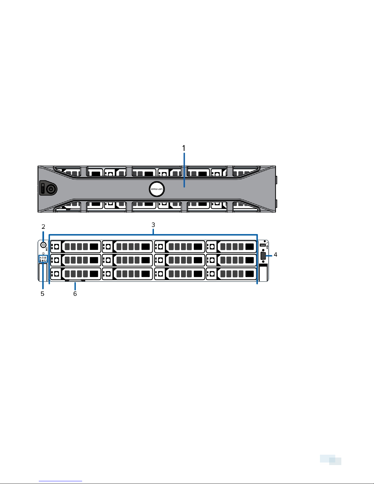
Front View
1. Bezel
The bezel protects the recorder from unauthorized physical access. The bezel must be removed to
access the front of the recorder.
2. Power button
Controls the power supply to the recorder.
3. Hard drives
Provides access to hot-swappable hard drives. There are LED indicators on each hard drive.
Some drives may contain an empty hard drive tray.
4. Video connector
Accepts a VGA monitor connection.
Introduction 1
Page 6
5. Diagnostic indicators
Provides information about system operations. For more information, see LED Indicators on page22.
6. Information tag
Provides the product service details, MAC addresses and a copy of the Windows license key.
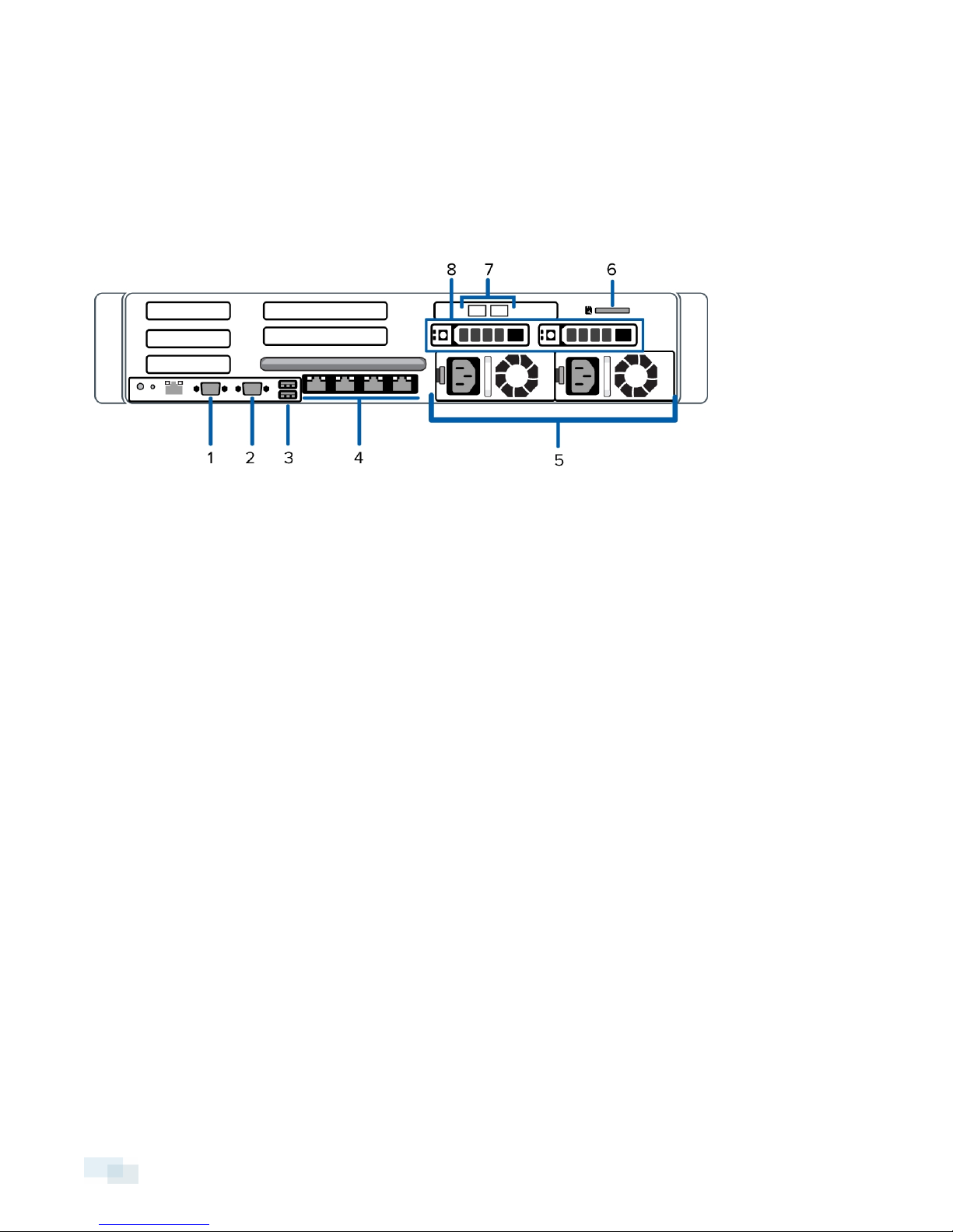
Back View
1. Serial connector
Accepts connections to serial devices.
2. Video connector
Accepts a VGA monitor connection.
3. USB connectors
Accepts USB connections to external devices.
4. 1 Gigabit Ethernet ports
Accepts an Ethernet connection to multiple networks.
5. Power supply
Two hot swappable redundant power supply.
6. SD card slot
Accepts an SD card.
7. 10Gigabit Ethernet ports
Accepts an Ethernet connection to multiple networks.
8. Operating system hard drives
Two hot-swappable 2.5 inch hard drives that are loaded with the operating system.
2 Back View
Page 7

Installation
Package Contents
Ensure the package contains the following:
l Avigilon HD Network Video Recorder
l Rack sliding rail assembly kit
l Cable management arm assembly kit
l Bezel and key
l Power cables
l Recovery USB — contains Windows® recovery software and supporting materials.
Installing the Rack Rails and Cable Management Arm
If the recorder will be kept in a server rack, install the Rack Sliding Rails and the Cable Management Arm
provided in the recorder package. Follow the procedures outlined in the Rack Installation Instructions and the
CMA Installation Instructions provided in the assembly kits.
NOTE: The supplied Rack Sliding Rails are compatible with square and round hole racks.
Connecting Cables
Refer to the diagrams in the Overview section for the location of the different connectors. Make any of the
following connections as required:
1. Connect a KVM switch or separate keyboard, mouse and monitor to the recorder.
l Keyboard and mouse can be connected to any USB port on the recorder.
l Monitor can be connected to any video connector at the front or back of the recorder.
2. Connect the recorder to your network using an Ethernet network cable.
3. Connect a power cable to each power supply at the back of the recorder.
4. Press the power button on the front of the recorder. Check that the recorder LED indicators display the
correct status.
Installing the Bezel
The bezel can be installed on the front of the recorder to help protect the power button and hard drives against
unauthorized access.
Installation 3
Page 8
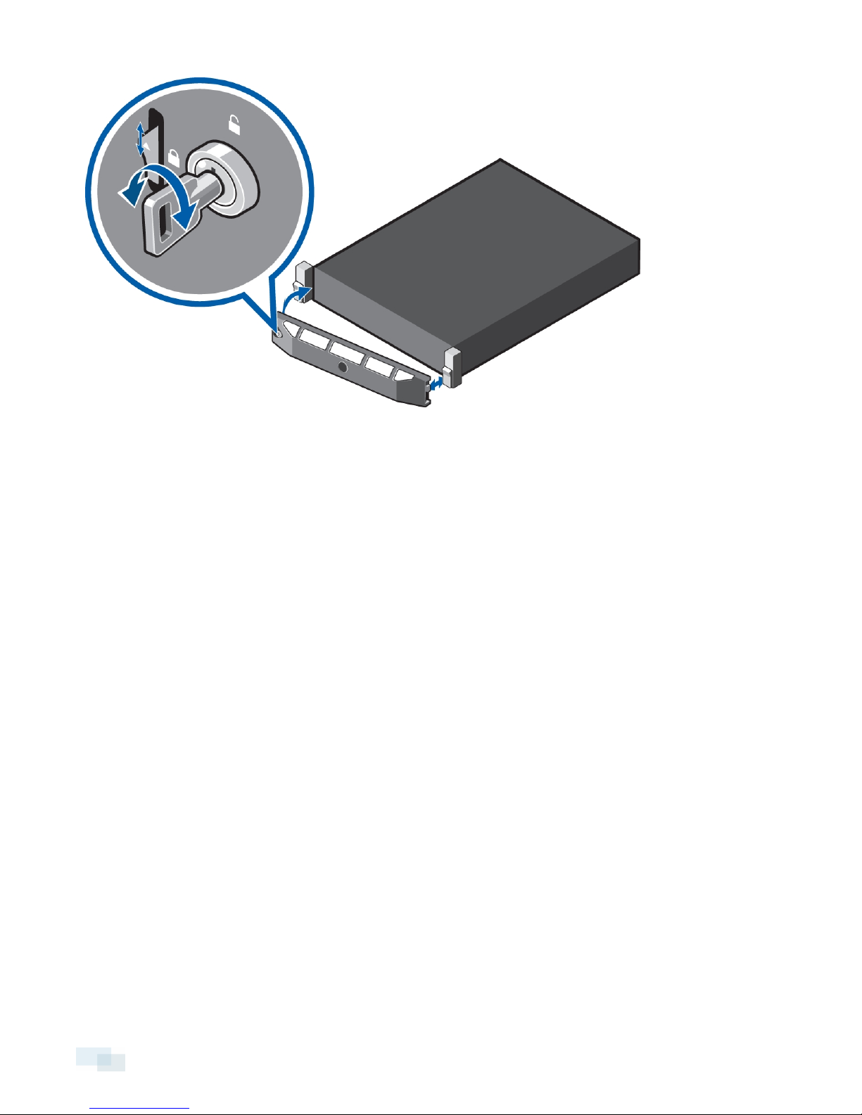
1. Slide the right end of the bezel against the right hinge of the recorder.
2. Push the left end of the bezel against the recorder until it clicks into place.
3. Use the provided key to lock the bezel.
Logging into Windows for the First Time
After the recorder powers up, Windows automatically starts.
l When you are prompted, enter the default administrator username and password:
username = Administrator
password = Avigilon
Windows finishes loading and you are immediately prompted to enter the Avigilon Control Center software
license key. For more information, see Licensing the Avigilon Control Center (ACC) System below.
By default, the operating system language is English. To change the language, see Changing the System
Language on page15
Licensing the Avigilon Control Center (ACC) System
Before you can configure cameras and monitor live or recorded video, you will need to activate your ACC
software license. The license is provided with the recorder. You will need to purchase a license if you don't
already have one.
After the recorder restarts, the first screen you see is the Avigilon Control Center software license wizard.
Other parts of the ACC system may start while you perform this procedure, but you will not be able to use any of
the features until after license activation is complete.
4 Logging into Windows for the First Time
Page 9

1. Click License Activation.
2. On the following screen, select one of the following:
l Internet Activation – If the recorder has an internet connection, select this option to quickly license
the Avigilon Control Center software.
l Manual Activation – If the recorder is not currently connected to the internet or you plan to keep
the system in a private intranet, select this option.
Internet Activation
1. On the Enter Product Key page, enter your license key. A green check mark will appear beside your
license key when it is correct.
2. Click Next.
3. On the Product Registration page, enter your contact information to receive product updates, then click
Next.
4. The Admin Tool connects to the Avigilon licensing server and activates the license.
When the Activation Succeeded message is displayed, click Finish.
Manual Activation
1. Click Step 1: Generate Activation File.
2. On the Enter Product Key page, enter your license key.
A green check mark will appear beside your license key when it is correct.
3. Click Next.
4. On the Select Activation File page, confirm where the activation file will be saved. Click [...] to navigate to
a different file location.
You can rename the activation file, but you must keep the .key extension.
5. Click Next.
On the following page, you will see the Activation File Saved message.
6. Find the saved activation file and copy the file to a computer with internet access.
7. Open a web browser and go to http://activate.avigilon.com.
8. At the Avigilon License Activation web page, click Browse to locate your activation file, then click
Upload.
9. The activated license file should download automatically. If not, allow the download to occur when you
are prompted.
10. Complete the product registration section to receive product updates from Avigilon, then click Register.
11. Find the downloaded license file and copy the file to the recorder.
12. If the Activation File Saved message is still displayed in the Add License wizard, click Ne xt. Otherwise
skip this step.
13. Click Step 2: Add License File.
14. On the Import License File page, click [...] to locate the license file, then click Next.
15. When the Activation Succeeded message is displayed, click Finish.
Internet Activation 5
Page 10

Adding Licenses
If you choose to upgrade your existing license to a different edition, you will need to perform the licensing
procedure again. In this case, you can access the Add License wizard from the Avigilon Control Center Server
Admin Tool software.
1. To open the Admin Tool, perform one of the following:
l Select All Programs or All Apps > Avigilon > Avigilon Control Center Server > Avigilon Control
Center Server Admin Tool.
l
From the recorder desktop, double-click .
2. In the Admin Tool window, select the Settings tab and click Licensing.
3. Click Add License.
4. Complete either the Internet Activation or Manual Activation procedure to add the new license to your
current system.
Networking
By default, the HD Network Video Recorder acquires an IP address on the network through DHCP. If you need to
set up the recorder to use a static IP address or any specific network configuration, see the Windows Help and
Support files for more information.
6 Adding Licenses
Page 11

Configuring the Avigilon Control Center Software
After you set up and license the HD Network Video Recorder, it is recommended that you complete the
following steps to configure the ACC system.
For more information about any of the following procedures, see the help files provided with the Avigilon
Control Center Client software.
Starting Up and Shutting Down the Avigilon Control Center Client Software 7
Logging Into and Out of a Site 8
Changing the Administrator Password 8
Connecting Cameras to the Avigilon Control Center System 9
Setting the Recording Schedule 10
Setting Data Aging 11
Adding Users and Groups 12
Advanced Settings 14
Starting Up and Shutting Down the Avigilon Control Center Client
Software
After you install the Avigilon Control Center Client software, start the application and access the HD Network
Video Recorder.
Starting Up the Client Software
Perform one of the following:
l In the Start menu, select All Programs or All Apps > Avigilon > Avigilon Control Center Client.
l
Double-click the shortcut icon on the desktop.
When you are prompted, log in to your site. You can only access cameras and video after you log in.
Once the application has started, it will automatically display a list of all the sites that are connected to the same
network, including the HD Network Video Recorder. You will be prompted to log in to all sites.
Shutting Down the Client Software
1.
In the top-right corner of the Client software, select > Exit.
2. When the confirmation dialog box appears, click Yes.
Configuring the Avigilon Control Center Software 7
Page 12

Logging Into and Out of a Site
After you start the Client software, you are immediately asked to log in to a site. By default, the HD Network
Video Recorder is automatically added to the system as a server within a site of the same name.
The default username is administrator with no password.
Logging In
1. Open the Site Login tab. The Site Login tab is automatically displayed if you are launching the Client
software for the first time.
To manually access the Site Login tab, do one of the following:
l
From the top-right corner of the window, select > Log In....
l
From the top of the application window, click to open the New Task menu, then click .
2. On the left side of the Site Login tab, select one or more sites.
If the site you want to log into is not shown, click Find Site... to discover the site.
3. Enter your username and password for the selected sites.
4. Click Log In.
You are logged into the selected sites.
If you want to be notified when new or disconnected sites come online, select the Notify me when additional
sites become available check box.
If you want to see the login page each time you launch the Client software, select the Show this tab on startup
check box. If you prefer not to login each time, you can disable this option and configure automatic login from
the Client Settings... dialog box.
Logging Out
You can log out of one or all sites at any time.
To... Do this...
Log out of one or select sites
Log out of all sites
l In the System Explorer, select one or more sites then right-click and
select Log Out.
1.
In the top-right corner of the Client, select > Log Out.
2. In the confirmation dialog box, click Yes.
Changing the Administrator Password
After you log in to the ACC system for the first time, it is recommended that you change the default administrator
password.
8 Logging Into and Out of a Site
Page 13

1.
At the top of the application window, click to open the New Task menu. When the menu appears,
click .
2.
In the Setup tab, click .
3.
In the following dialog box, select the administrator user name and click .
4. Click Change Password....
5. In the following dialog box, enter a new password and then confirm the new password.
6. Click OK.
Tip: If you forget the default administrator password, resetting the password requires restoring the factory
default settings on every server in the site. To avoid this issue, it is highly recommended that you create at least
one other administrator level user as a backup.
Connecting Cameras to the Avigilon Control Center System
After all the cameras in your system have been physically connected to the network, you need to connect the
cameras to the ACC system so that video can be recorded and indexed for search.
1.
In the site Setup tab, click .
The Connect/Disconnect Cameras... tab is displayed.
2. In the Discovered Cameras area, select one or more devices then click Connect....
Tip: You can also drag the device to a server on the Connected Cameras list.
3. In the Connect Camera dialog box, select the server you want the device to connect to.
NOTE: If you are connecting multiple devices, all the cameras must use the same connection settings.
4. If you are connecting a third-party device, you may choose to connect the device by its native driver. In
the Camera Type: drop down list, select the device's brand name. If there is only one option in the drop
down list, the system only supports one type of driver from the device.
5. If the camera supports a secure connection, the Camera Control: drop down list is displayed. Select one
of the following options:
NOTE: The setting may not be displayed if the camera only supports one of the options.
l Secure — The system will protect and secure the camera's configuration and login details. This
option is selected by default.
l Unsecure — The camera's configuration and login details will not be secured and may be
accessible to users with unauthorized access.
Cameras with a secure connection are identified with the icon in the Status column.
ConnectingCameras tothe Avigilon Control Center System 9
Page 14

6.
If it is not displayed, click to display the Site View Editor and choose where the device appears in the
System Explorer.
l If your site includes virtual sub-sites, select a location for the device. The list on the right updates to
show what is stored in that directory.
l In the site directory, drag the device up and down to set where it is displayed.
l If you are connecting multiple devices at the same time, the selected devices must be assigned to
the same sub-site.
Tip: If the site you want is not listed, you may need to connect the device to a different server. Make sure
the selected server is connected to the site you want.
7. Click OK.
8. If the device is password protected, the Camera Authentication dialog box appears. Enter the device's
username and password, then click OK.
Setting the Recording Schedule
Once all the cameras have been connected, you can set when you want each camera to record video.
By default, all connected cameras are set to record when events are detected by the system. You can skip this
procedure if you prefer to keep the default settings.
Before you can assign a recording schedule, you must create a template. The template allows you to assign the
same schedule to multiple cameras.
Creating a Recording Template
The events that can be selected for the template depend on the licensed features in your system.
1.
In the server Setup tab, click . The Recording Schedule dialog box is displayed.
2. Click Add Template below the Templates: list.
3. Enter a name for the New Template.
4. Click the Se t Area button, then click or drag the cursor across the Recording Mode: timeline to set the
types of events that the cameras will record throughout the day. Individual rectangles on the Recording
Mode: timeline are colored when they have been selected.
The Recording Mode: options include:
l Continuous — record video constantly.
l Motion — Only record video when motion is detected.
5. To disable recording in parts of the template, click the Clear Area button, then click or drag the cursor
across the timeline to remove the set recording areas.
6. If cameras are not recording in Continuous mode all day, you can set cameras to record reference images
between events in the recording schedule.
l Select the Record a reference image every: check box, then set the time between each
reference image.
10 Setting the RecordingSchedule
Page 15

Setting Up a Weekly Recording Schedule
You can set up a weekly recording schedule by applying templates to cameras for each day of the week.
1.
In the server Setup tab, click . The Recording Schedule dialog box is displayed.
2. Select a template from the Templates: list.
3. In the Default Week area, click the days of the week this template applies to for each camera.
Figure 1: The Recording Schedule dialog box: Default Week
4. Click OK.
Setting Data Aging
Data aging defines how long recorded video is stored and the quality of the video as it ages over time. In the
ACC system, the recorded image rate is slowly reduced so that recorded video can be viewed over a longer
period of time while still making room for new recordings. You can adjust how long the full image rate video is
kept, so that you have the best quality video when you need it.
The amount of data aging that is available depends on the camera you have connected to your system:
l For JPEG2000 or JPEG compression cameras, data aging is available at three rates:
l High Bandwidth keeps recordings at their original quality.
l Half Image Rate discards half of the recorded data to make room for new recordings.
l Quarter Image Rate keeps 1/4 of the original recorded data so that you can still see older video.
l For H.264 cameras that support data aging, data aging is available at two rates:
l High Bandwidth keeps the original high quality video and the secondary stream of low resolution
video.
l Low Bandwidth only keeps the secondary stream of low resolution video.
NOTE: The Data aging can only occur when the secondary stream is enabled.
l For H.264 cameras that do not support data aging, only the High Bandwidth video is kept.
By default, the system is set to keep recorded video for the maximum amount of time based on the available
storage.
NOTE: The time shown in the Total Record Time column is an estimate only.
Setting Up a WeeklyRecordingSchedule 11
Page 16

1.
In the server Setup tab, click .
The Recording and Bandwidth dialog box is displayed.
The Data Aging column shows an estimate of the recording time that is available at each image rate,
given the amount of space on the recording device.
2. In the Data Aging column, move the sliders to adjust the amount of time video is stored at each image
rate.
l To change the data aging settings for all linked cameras, move the slider for one linked camera
and all linked cameras will be updated.
l To change the data aging setting for one camera, break the camera's link to other cameras by
clicking the icon to the left of its name, then make your changes.
3. In the Max. Record Time column, manually enter a maximum record time or select one of the options from
the drop down list for each camera.
NOTE: If the time estimated in the Total Record Time column is shorter than what is set in the Max. Record
Time column, the camera's actual recording time will be shorter than the Max. Record Time.
4. Click OK.
Adding Users and Groups
If there will be other people using the system, you may want to add them as separate users rather than giving
them access through the default administrator account.
Before you can add individual users, you will need to add permission groups that define what users have access
to. By default, the system has the following groups:
l Administrators — has access to everything in the system.
l Power Users — has access to most features in the system except for the ability to import and export
settings.
l Restricted Users — has access to live video only and can control audio and digital outputs.
l Standard Users — has access to live and recorded video, but cannot make any Setup changes.
It is highly recommended that the Administrators group includes at least two users. In the event one administrator
user forgets the default administrator password, the second administrator user can be used to reset the
password. If you do not have a second administrator user, you may need to completely reset the system.
12 Adding Users and Groups
Page 17

Adding Groups
1.
In the site Setup tab, click .
2.
In the following dialog box, select the Groups tab and click .
3. In the pop-up dialog box, select an existing group to use as a template for your new group, then click OK.
4. In the Edit Group dialog box, complete the following:
a. Give the new group a name.
b. Select a rank for the group from the Rank: drop down list. To edit or view the entire Corporate
Hierarchy, click .
c. Select the required Group Privileges: and Access Rights: for the group. Clear the check box of any
feature or device that you do not want the group to have access to.
5. Select the Members tab to add users to the group.
If a user is added to the group through the Add User dialog box, the user is automatically added to the
group's Members list.
a.
Click .
b. Select the users that should be part of this new group. Only users that have been added to the site
are displayed.
Tip: Enter the name of a user in the Search... field to locate specific users.
c. Click Add. The users are added to the Members list.
6. Click OK to save the new group.
Adding Users
1.
In the site Setup tab, click .
2.
In the Users tab, click .
3. When the Add User dialog box appears, complete the User Information area.
4. If you don’t want this user to be active yet, select the Disable user check box. Disabled users are in the
system but cannot access the site.
5. In the Login Timeout area, select the Enable login timeout check box to set the maximum amount of time
the Avigilon Control Center Client software can be idle before the user is automatically logged out of the
application.
6. In the Password area, complete the following fields:
l Password: — enter a password for the user.
l Confirm Password: — re-enter the password.
l Require password change on next login — select this check box if the user must replace the
password after the first login.
l Password Expiry (Days): — specify the number of days before the password must be changed.
l Password never expires — select thischeck box if the password never needs to be changed.
Adding Groups 13
Page 18

7. In the Member Of tab select the check box beside each access group the user belongs to.
The other columns display the permissions that are included in the selected groups.
8. Click OK. The user is added to the site.
Repeat this procedure to add all the users that are required.
Advanced Settings
After you've set up all the required settings in the ACC Client software, the system can start running.
The following list provides some advanced settings you can use to further customize your system. See the
application Help files for details about how to configure each setting.
l Adjust camera settings
l If camera video looks slightly blurry or unclear, you can adjust the camera's Image and Display
settings.
l If you want the camera to record at a different image rate, you can adjust the camera's
Compression and Image Rate settings.
l To reduce the amount of ambient motion detection for a specific camera, you can adjust the
Motion Detection settings.
l To maintain the privacy of certain areas, you can set Privacy Zones in the camera's field of view so
that private spaces are never recorded.
l Corporate Hierarchy
l If you are setting up an enterprise system that includes large, physically dispersed Sites, you can
use the Corporate Hierarchy feature to define system access at different levels of the organization.
l Alarms
l Use the Alarms dialog box to create and manage alarms. Once an alarm has been created, you can
monitor alarm events in the Alarms tab and in the ACC Mobile App.
l Self-Learning Video Analytics
l If you have an Avigilon self-learning video analytics device, use the Video Analytics Configuration
dialog box to configure classified object motion detection. Once configured, you can receive
events, trigger alarms, define rules, and record video when specific object motion requires your
attention.
l Email notifications
l You can set up an SMTP email server to send you email notifications when system events occur.
l If you have a Standard Edition licensed system, you can set up detailed rules to send you email
notifications when specific events occur.
l Setup the Gateway
l The ACC Gateway software allows you to access video from a remote web browser or mobile
device. If the Gateway software is not set up, you cannot access video outside of your local
network.
l Install the ACC Mobile app on your mobile device so that you can remotely monitor live and
recorded video.
14 Advanced Settings
Page 19

Advanced Features
Changing the System Language
By default, the recorder's operating system language is English.
1.
From the bottom-left corner of the Windows desktop, click .
2.
In the Start menu, click .
3.
In the following window, click .
4.
On the next page, click .
5. In the following window, click the first option in the light blue bar. The option is labeled Add a language.
6. On the next page, scroll down the language list then double-click your preferred language.
NOTE: Only the languages supported by the Avigilon Control Center software are pre-installed. You can
choose to download and install any extra languages supported by Windows.
If there are multiple variants of the language available, you will be asked to double-click your preferred
locale.
The selected language is added to the system language list.
7. In the last column on the right, click the blue link. The link is labeled Options.
8. On the following page, click the first blue link on the page. The link is labeled Make this the primary
language.
NOTE: Do not click the link with this icon at the front, or you may uninstall the language from the
system.
9. You are prompted to log off to apply the language changes. You can choose to log off now or log off
later.
l To log off immediately, click the left button that is labeled Log off now.
l To log off later, click the right button that is labeled Log off later.
The next time you log in to Windows, the selected system language is displayed.
You can now decide if you want the operating system to maintain one or multiple languages.
l To maintain one language, return to the Language window that contains the system language list and
delete English.
l To maintain multiple languages, return to the Language window and add the other required languages.
You can order the languages by importance by moving them up and down the list.
Advanced Features 15
Page 20

Checking System Health
The Server Administrator software is pre-installed on the recorder. The software provides information about the
recorder’s system operation status, and gives you remote access to the recorder for recovery operations.
If one of the LED indicators on the recorder is flashing an error warning, the Server Administrator will display
details about the problem. For more information about the LED indicators, see LED Indicators on page22.
1. Open the Server Administrator.
l To open the Server Administrator locally, double-click the Server Administrator shortcut icon on
the desktop.
l To open the Server Administrator remotely, open a web browser and enter this address:
https://<recorder IP Address>:1311/
For example: https://192.168.1.32:1311/ or https://localhost:1311/
If you are using an intranet connection, your browser may display an error message. Allow the browser to
ignore the certificate warnings.
2. On the login screen, enter the Windows software administrator username and password that was
configured for the recorder.
3. On the Server Administrative home page, the health of the system components are displayed in the
workspace on the right.
l To see the health of other system components, expand and select a different component from the
System Tree on the left.
l The table displayed in the workspace lists system components and their status:
The system component is running normally.
The system component has a non-critical warning.
The system component has a critical failure.
The system component status is unknown.
l To see the details of a system component, select the system component from the workspace.
For more information about the features in the Server Administrator, see the Help system provided in the
software. The System Administrator is also the tool used to customize the RAID settings, assign a hot spare and
remotely monitor the system health.
Replacing a Hard Drive Blank
Depending on the recorder model, there may be hard drive blanks at the front of the recorder. You can replace
the blanks with hard drives as required.
16 Checking System Health
Page 21

1. Remove the bezel.
a. Unlock the bezel.
b. Lift the release latch next to the lock.
c. Pull the left end of the bezel then unhook the right end to remove the bezel.
2. Press the release button and slide the blank out of the hard drive slot.
3. Insert the hard drive all the way into the recorder then push the handle against the hard drive to lock it into
place.
Replacing a Hard Drive Blank 17
Page 22

4. Open the Server Administrator application and expand the System Tree.
The new hard drive should be automatically added to the Physical Disks list. The list is typically available
here:System > Storage > PERC H730 > Connector 0 >Enclosure > Physical Disks.
5. Assign a task to the new hard drive or allow it to exist as a extra storage drive.
It is recommended that individual new hard drives be used as hot spares. Hot spares are hard drives that
are available on standby in the event of a hard drive failure in the RAID. If that occurs, you can configure
the system to automatically redirect recording to the unused hard drive.
To assign the new hard drive as a hot spare, select Assign and Unassign Global Hot Spare from the Task
list then click Execute.
If the new hard drive is not displayed in the Server Administrator, try one of the following:
l Refresh the browser.
l Reboot the recorder.
l In the System Administrator, select PERC H730 in the System Tree then click Information/Configuration in
the right workspace. Next, select Rescan from the Controller Tasks list then click Execute.
Replacing Hard Drives
The hard drives on the HD Network Video Recorder are set up in a Redundant Array of Independent Disks (RAID)
configuration. This allows information to be recorded across several hard drives.
If one or two hard drives fail, there is enough information on the other hard drives for the recorder to continue
recording video.
The operating system and the Avigilon Control Center software are mirrored on two hard drives at the back of
the recorder. If one of the hard drives fail, you can replace the failed drive while the recorder continues to run
from the other.
If your recorder is still under warranty, contact Avigilon Technical Support to replace the failed hard drive.
If more than two hard drives fail at the same time, contact Avigilon Technical Support immediately for recovery
instructions.
Important: Only replace a hard drive if the hard drive LED indicator and the Server Administrator displays an error.
1. Open the Server Administrator.
2. Check which hard drive has failed, then disconnect the drive through the Server Administrator software.
Hard drives are installed at the front, back and in the middle of the recorder. Be sure you can identify
which hard drive needs to be replaced.
3. If you are replacing a hard drive at the center of the recorder, shut down the recorder then disconnect all
cables.
NOTE: Skip this step if you plan to hot-swap a hard drive at the front or back of the recorder.
4. Remove the bezel.
5. Depending on where the hard drive is located, perform one of the following procedures:
18 Replacing Hard Drives
Page 23

Replacing Front or Back Hard Drives 19
Replacing Center Hard Drives 19
Replacing Front or Back Hard Drives
1. Locate the failed hard drive at the front or back of the recorder.
2. Press the release button on the front left of the hard drive.
3. When the handle is released, pull the hard drive out of the recorder.
4. Remove the four screws from the side of the hard drive carrier.
5. Lift the failed hard drive out of the carrier.
6. Insert a new hard drive into the carrier then screw it into place. The hard drive connectors should face the
back.
7. When the hard drive is secured in the carrier, insert the hard drive back into the recorder.
8. Once the hard drive is inserted all the way in, push the handle against the hard drive to lock it into place.
The recorder immediately starts rebuilding the hard drive. The progress is displayed in the Server Administrator.
This may take several hours.
Replacing Center Hard Drives
To replace a hard drive stored in the middle of the recorder, complete the following steps:
Replacing Front or BackHard Drives 19
Page 24

1. At the top of the recorder, unlock the latch release then lift and rotate the latch towards the back of the
recorder.
The cover slides back and is released from the recorder body.
2. Hold the cover on both sides and lift it off the recorder.
3. Locate the failed hard drive on the center hard drive tray.
20 Replacing Center Hard Drives
Page 25

4. Lift the handles on either side of the hard drive tray.
5. Press the orange release tab on the hard drive tray then lift up the hard drive carrier handle to release the
hard drive.
6. Hold the handle and lift the hard drive out of the tray.
7. While holding the handle, pull the edges of the carrier away from the hard drive to remove the failed hard
drive from the carrier.
8. Align the slots on the new hard drive to the tabs on the hard drive carrier.
9. Pull the edges of the carrier over the slots on the hard drive.
10. Place the new hard drive into the tray and push the handle down until the hard drive clicks into place.
11. Fold down the handles on the hard drive tray.
12. Close and lock the recorder cover.
13. Reconnect all the cables to the recorder.
14. Power the recorder.
After the operating system starts up, the recorder immediately starts rebuilding the hard drive. The progress is
displayed in the Server Administrator. This may take several hours.
Replacing Center Hard Drives 21
Page 26

LED Indicators
The following tables describe what the LEDs on the recorder indicate.
Diagnostic Indicators
The diagnostic indicators on the front of the recorder highlight system issues during system startup.
NOTE: The diagnostic indicators only light-up when the recorder is powered.
LED Indicator Description
l Blue — the recorder is powered and is in good health.
l Blinks orange — the recorder is powered but an error exists. Errors include: a failed fan
Health
Hard drive
or hard drive.
l Blinks orange — the hard drive is experiencing an error.
l Blinks orange — the recorder experiences an electrical error. Errors include: voltage out
of range, or failed power supply or voltage regulator.
Electrical
Check the power status indicator to confirm if it is an issue with the power supply.
l Blinks orange — the recorder experiences a thermal error. Errors include: temperature
out of range or fan failure.
Temperature
Check that the recorder fan is functioning correctly and the air vents are not blocked.
l Blinks orange — the recorder experiences a memory error.
Memory
l Blinks orange — the recorder experiences a PCIe card error.
PCIe
Restart the recorder then update the drivers for the PCIe card.
Power Status Indicators
The power button on the front of the recorder lights up when power is on.
Additional information about the power supply is provided by the power status indicator on the back of the
recorder. The following table describes what the LEDs indicate:
22 LEDIndicators
Page 27

Figure 2: (1)The power status indicator.
LED Indicator Description
Off Power is not connected.
Green Power is supplied to the recorder.
Flashing green Firmware update is being applied to the power supply unit.
Flashing green then turns off
The redundant power supply is mismatched. This only occurs if
you have a secondary redundant power supply installed.
Flashing orange There is a problem with the power supply.
Network Link Status Indicators
When the recorder is connected to the network, the recorder’s connection status LEDs above the Ethernet port
display the recorder’s connection status to the network. The following table describes what the LEDs indicate:
Figure 3: (1)Link LED. (2)Conn ection Status LED
LED Indicator Description
Off The recorder is not connected to a network.
Link LED is green
Link LED is orange
Connection Status LED is blinking green
Network Link Status Indicators 23
The recorder is connected to a network at the maximum port
speed (1 Gbps or 10 Gbps).
The recorder is connected to a network at less than the maximum
port speed.
The recorder is working with other parts of the Avigilon Control
Center software.
Page 28

Hard Drive RAID Status Indicators
Each hard drive has its own set of LED indicators to show its activity and status.
Figure 4: (1)Status LED. (2) Activity LED
The Activity LED flashes green when the hard drives are working. The following table describes what the Status
LEDs indicate:
LED Indicator Description
Green The hard drive is online.
Off The hard drive is disconnected from the recorder.
Two short gree n flashes every second
Flashes green, orange then off The hard drive is predicted to fail.
Four short orange flashes per second The hard drive has failed.
Flashes green slowly The hard drive is rebuilding.
Blinks green for three seconds, orange for
three seconds and off for six seconds
The system is identifying a new hard drive, or preparing a hard
drive for removal.
The hard drive rebuild has been aborted.
24 Hard Drive RAID Status Indicators
Page 29

Specifications
System
Avigilon Control Center Software Enterprise, Standard and Core
Operating System Windows Server 2012 R2
Hard DiskDrive Configuration Near-line SAS, hot swappable, RAID 6
Mechanical
Dimensions (H x W x D) 8.73 cm (3.44 in.) x 48.24 cm (18.99 in.) x 71.6 cm (28.19 in.)
Weight 32.5 kg (71.65 lb) when fully populated with hard disk drives
Form Factor 2U rack
Electrical
Power Input 100 to 240 VAC, 50/60 Hz, auto-switching
Power Consumption 750 W
Power Supply Dual-redundant, hot swappable
Environmental
Operating Temperature 10° C to 35° C (50° F to 95° F)
Storage Temperature –40°C to 65°C (–40°F to 149°F)
Humidity
Operating Vibration 0.26 Grms at 5 Hz to 350 Hz (all operation orientations).
Storage Vibration 1.88 Grms at 10 Hz to 500 Hz for 15 min (all six sides tested).
Operating Shock
Storage Shock
Operating Altitude 3048 m (10,000 ft).
Storage Altitude 12,000 m (39,370 ft)
Certifications
Safety
Power Efficiency
5% to 95% relative humidity with 33°C (91°F) maximum dew point
(non-condensing)
Six consecutively executed shock pulses in the positive and
negative x, y, and z axes of 40 G for up to 2.3 ms.
Six consecutively executed shock pulses in the positive and
negative x, y, and z axes (one pulse on each side of the system) of
71 G for up to 2 ms.
EN 60950-1:2006 / A11:2009 / A1:2010 / A12:2011 / A2:2013
UL/CSA/IEC 60950-1, 2 Ed + Am 1: 2009 + Am 2: 2013
EN 62311:2008
80 PLUS Titanium
ENERGY STAR 2.0
Electromagnetic Emissions
Specifications 25
US CFR Title 47, FCC Part 2, 15
Canadian ICES-003(A) Issue 5
Page 30

EN 55022:2010/CISPR 22:2010
EN 61000-3-2:2006 +A1:2009 +A2:2009/IEC 61000-3-2:2005
+A1:2008 +A2:2009 (Class D)
EN 61000-3-3:2008/ IEC 61000-3-3:2008
Electromagnetic Immunity EN 55024:2010/CISPR 24:2010
Directives RoHS, Reach (SVHC), WEEE
26 Specifications
Page 31

Limited Warranty and Technical Support
Avigilon warrants to the original consumer purchaser that this product will be free of defects in material and
workmanship for a period of 3 years from date of purchase.
The manufacturer’s liability hereunder is limited to replacement of the product, repair of the product or
replacement of the product with repaired product at the discretion of the manufacturer. This warranty is void if
the product has been damaged by accident, unreasonable use, neglect, tampering or other causes not arising
from defects in material or workmanship. This warranty extends to the original consumer purchaser of the
product only.
AVIGILON DISCLAIMS ALL OTHER WARRANTIES EXPRESSED OR IMPLIED INCLUDING, WITHOUT LIMITATION,
ANY IMPLIED WARRANTIES OF MERCHANTABILITY OR FITNESS FOR A PARTICULAR PURPOSE, EXCEPT TO
THE EXTENT THAT ANY WARRANTIES IMPLIED BY LAW CANNOT BE VALIDLY WAIVED.
No oral or written information, advice or representation provided by Avigilon, its distributors, dealers, agents or
employees shall create another warranty or modify this warranty. This warranty states Avigilon’s entire liability
and your exclusive remedy against Avigilon for any failure of this product to operate properly.
In no event shall Avigilon be liable for any indirect, incidental, special, consequential, exemplary, or punitive
damages whatsoever (including but not limited to, damages for loss of profits or confidential or other
information, for business interruption, for personal injury, for loss of privacy, for failure to meet any duty including
of good faith or of reasonable care, for negligence, and for any other pecuniary or other loss whatsoever) arising
from the use of or inability to use the product, even if advised of the possibility of such damages. Since some
jurisdictions do not allow the above limitation of liability, such limitation may not apply to you.
This Limited Warranty gives you specific legal rights and you may also have other rights which vary from
jurisdiction to jurisdiction.
Warranty service and technical support can be obtained by contacting Avigilon Technical Support by phone at
1.888.281.5182 or via email at support@avigilon.com.
Limited Warranty and Technical Support 27
 Loading...