

Page 1

Installing the NVR Connectivity and 2
Avigilon provides two optional kits for network video recorders (NVR):
l NVR Connectivity Kit (HD-NVR3-PRMEXP-DAS-CONNECT-KIT) provides all the components needed for
an NVR Premium to support an NVR external storage expansion. Including the components in the 2nd
CPU Kit.
NOTE: NVR Connectivity Kit is currently only available for NVR Premium.
l 2nd CPUKit (HD-NVR3-PRM-2NDCPU or HD-NVR3-STD-2NDCPU) provides all the components needed to
add CPU redundancy to an NVR Premium or Standard.
NOTE: If the HDNVR is an operating part of your surveillance system, be aware that it must be shut down to
complete this procedure.
The installation procedure for both kits is very similar. If you are only installing the 2nd CPU Kit, skip the HBA
procedure.
Install the kit components in the following order :
Confirm Package Contents 1
nd
CPU Kits
Required Tools 2
1. Remove the NVR Cover 2
2. Install the CPU 3
3. Install RAM 5
4. Install HBA 6
5. Restoring the NVR 7
Confirm Package Contents
Confirm that the kit you are installing contain the following components:
Installing the NVR Connectivity and 2nd CPU Kits 1
Page 2
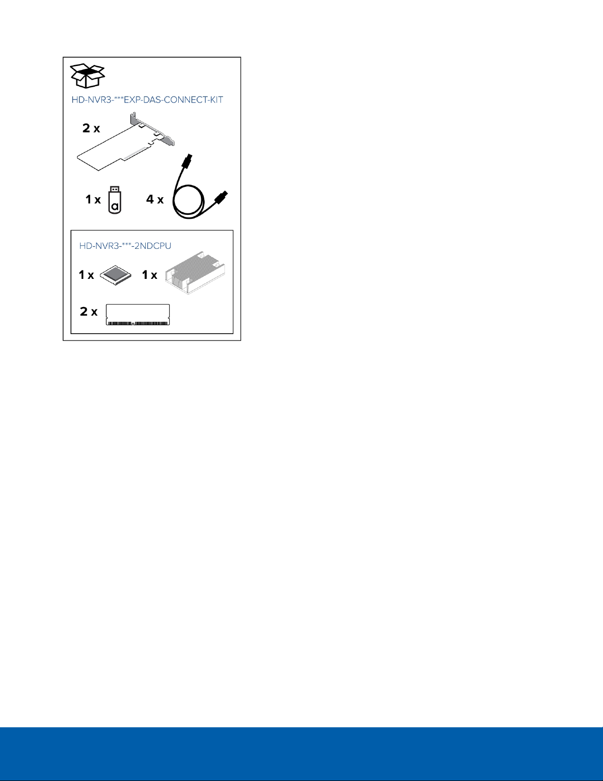
l NVR Connectivity Kit (HD-NVR3-***EXP-DAS-CONNECT-KIT):
o
2nd CPU Kit (included in the NVR Connectivity Kit and
also available as a standalone kit — HD-NVR3-***2NDCPU)
l 1 x CPU
l 1 x heat sink
l 2 x 8GB RAM
o
2 x HBA cards
o
4 x SAS cables
o
1 x USB — contains configuration software
Required Tools
The following tool is not included in the kit package, but is required to complete the installation:
l Philllips #2 screwdriver
It is recommended that you use a static mat or static strap to ground yourself against static shock.
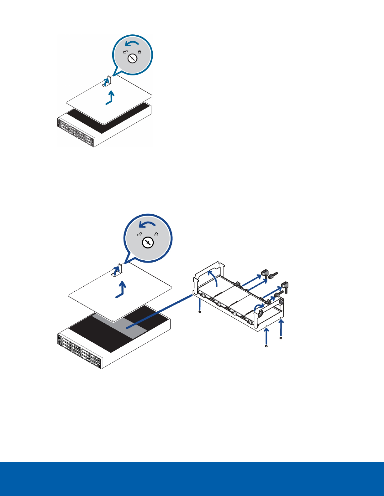
1. Remove the NVR Cover
1. Shut down the recorder.
You can skip this step if you are installing the kit on a new recorder.
a. In the Avigilon Control Center (ACC) Admin Tool, click Shut Down.
Wait for the application to display this message:
Control Center Server is Not Running
b. Shut down Windows.
2. Remove all network, power and peripheral cables from the recorder.
3. At the top of the recorder, unlock the latch release then lift and rotate the latch towards the back of the
recorder.
The cover slides back and is released from the recorder body.
Required Tools 2
Page 3
2. Install the CPU
While the recorder is open, install the CPU from the kit.
1. If you are installing the CPU on a Premium recorder, remove the center hard drive tray.
a. Disconnect the SATA cables connected to the center hard drive tray.
b. Fold the hard drive tray handles up.
c. Use the handles to lift the tray out of the recorder.
2. Remove the CPUblank immediately over the second CPUslot.
3. Unpack the CPU from the kit and peel off the protective layer of plastic on the bottom.
Be careful not to touch the thermal paste that is pre-applied to the bottom of the CPU.
2. Installthe CPU 3
Page 4

4. Locate the processor socket.
5. Release the lever beside the unlock icon. Push the lever down and out from under the tab.
6. Release the lever beside the lock icon in the same way.
7. Lift open the processor shield.
8. Align the CPU with the processor socket key notches and make sure the pin-1 indicator on the CPU aligns
with the triangle on the socket.
NOTE: Do not force the processor into the socket. The processor should slide easily into the socket
when aligned correctly.
9. Close the processor shield and secure the release levers back into place.
10. Place the heat sink over the CPU processor socket.
Make sure the screws on the heat sink line up with the holes on the processor socket.
2. Installthe CPU 4
Page 5

11. Use a Phillips #2 screwdriver to tighten the screws on the heat sink. It is recommended that after you
tighten the first screw, you tighten the screws that is diagonally opposite.
NOTE: Do not over-tighten or strip the screws.
3. Install RAM
After the CPU has been installed, insert RAM included in the kit into memory sockets B1 and B2.
1. In the row of empty memory sockets to the right of the newly installed CPU, locate B1 and B2.
2. Press the RAM into sockets until the socket levers click into place.
3. Install RAM 5
Page 6

4. Install HBA
You can skip this procedure if you are installing the CPU (HD-NVR3-xxx-2NDCPU) kit, which does not include a
host bus adapter (HBA).
The connectivity kit (HD-NVR3-xxxEXP-DAS-CONNECT-KIT) contains 2 x HBA. The HBA must be installed to PCI
slot 5 on riser 2 and PCI slot 6 on riser 3.
Tip: It is highly recommended that you write down the SASaddress for each of the HBA before installing them
into the recorder. The SAS address can be used to help troubleshoot any network storage issues that may arise.
1. Lift the blue expansion card latch for riser 3 out of the recorder.
2. Disconnect the 10GbE converged network adapter (CNA) that is already installed in PCI slot 6.
3. Carefully pull the CNA board out of the PCI slot. You will be re-installing the CNA board into a different slot
later in this procedure.
4. Insert and press one of the HBA boards into slot 6. The board pins should be inserted all the way into the
riser.
5. Lift the blue expansion card latch for riser 2 out of the recorder.
6. Remove the protective grill over PCI slot 4 and 5.
4. Install HBA 6
Page 7

7. Insert and press the other HBA board into the lower slot 5. The board pins should be inserted all the way
into the riser.
8. Insert and press the CNAboard that you previously removed into the upper slot 4. The card should click
into place and the pins are inserted all the way into the riser.
9. Push the blue expansion card latches back into place.
5. Restoring the NVR
When all the components have been installed, restore the removed components and close the cover.
5.Restoring the NVR 7
Page 8

1. Reinstall the components that were immediately over the CPU.
l Reinstall the center hard drive tray. Make sure the SATA cables are all reconnected.
2. Close and lock the recorder cover.
3. Reconnect all the cables to the recorder.
4. Power the recorder.
©2016 - 2017,Avigilo n Corpor ation. All rights re served . AVIGILON, Avigilon logo, Avig ilo n Control Center, ACCand T RUST ED SECURITY SOLUT IONS ar e re gis tere d trade marks o f
Avigilo n Cor poration. . Other names mentioned here in may be the trade marks of their re sp ective o wners . The abs ence o f the symbo ls ™ and ® in pr oximity to each trademark in this
document is not a disclaimer of owner ship of the re lated trade mark. Avig ilo n Cor por ation p rote cts its innovations wi th patents issued in the U nited States of America and other
jurisd ictions wor ldwide : htt p:// www.avigilon .com/ patents. U nless stated exp licitly and in writing, no license is gr anted with re sp ect to any co pyri ght, i ndustrial des ign, trade mark,
patent o r other intellectual p roper ty r ights of Avigilon Corpo ration or its lice nsors.
Avigilo n Cor poration
http://www.avigi lon.com
PDF-CPUCNCT-KIT-A
Revision: 2 - EN
201702 17
5.Restoring the NVR 8
 Loading...