

Page 1

User Guide
Avigilon High Definition H.264 IP Camera Models:
HD-H264-B1, HD-H264-B2, HD-H264-D1, HD-H264-DC1, HD-H264-DO1
and HD-H264-DP1
UG-H264-A-Rev2
Page 2

Copyright © 10/20/11 Avigilon. All rights reserved.
No copying, distribution, publication, modification, or incorporation of this document, in
whole or part, is permitted without the express written permission of Avigilon. In the
event of any permitted copying, distribution, publication, modification, or incorporation of
this document, no changes in or deletion of author attribution, trademark legend, or
copyright notice shall be made. No part of this document may be reproduced, stored in a
retrieval system, published, used for commercial exploitation, or transmitted, in any form
by any means, electronic, mechanical, photocopying, recording, or otherwise, without
the express written permission of Avigilon.
Windows and Internet Explorer are trademarks of Microsoft Inc.
Mac, Apple, and Safari are trademarks of Apple Inc.
iOS is a trademark of Cisco licensed to Apple.
Opera is a trademark of Opera Software ASA.
Android is a trademark of Google Inc.
Avigilon has made every effort to identify trademarked properties and owners on this
page. All brands and product names used in this document are for identification
purposes only and may be trademarks or registered trademarks of their respective
companies.
Avigilon
Tel +1.604.629.5182
Fax +1.604.629.5183
http://www.avigilon.com
Revised 10/20/11
Page 3

Table of Contents
Introduction . . . . . . . . . . . . . . . . . . . . . . .1
System Requirements . . . . . . . . . . . . . . . . . . . . 1
Accessing the Camera Web Interface . .2
Live View . . . . . . . . . . . . . . . . . . . . . . . . . . . . . . 3
About . . . . . . . . . . . . . . . . . . . . . . . . . . . . . . . . . 3
Setup . . . . . . . . . . . . . . . . . . . . . . . . . . . . .4
General . . . . . . . . . . . . . . . . . . . . . . . . . . . . . . .4
Network . . . . . . . . . . . . . . . . . . . . . . . . . . . . . . . 5
Image and Display . . . . . . . . . . . . . . . . . . . . . .6
Compression and Image Rate . . . . . . . . . . . . .8
Configuring RTSP Stream URI . . . . . . 10
Motion Detection . . . . . . . . . . . . . . . . . . . . . . . 10
Privacy Zones . . . . . . . . . . . . . . . . . . . . . . . . .12
Adding Privacy Zones . . . . . . . . . . . . .12
Removing Privacy Zones . . . . . . . . . .13
Digital Inputs and Outputs . . . . . . . . . . . . . . . . 13
Microphone . . . . . . . . . . . . . . . . . . . . . . . . . . .14
Users . . . . . . . . . . . . . . . . . . . . . . . . . . . . . . . . 14
Adding a User . . . . . . . . . . . . . . . . . . . 15
Editing Users and Passwords . . . . . . .15
System . . . . . . . . . . . . . . . . . . . . . . . . . . . . . . 16
Upgrading the Camera Firmware . . . .16
Device Log . . . . . . . . . . . . . . . . . . . . . . . . . . . 17
English
Page 4

English
Page 5

Introduction
All Avigilon High Definition H.264 IP Cameras and Dome Cameras
contain a web interface that allows you to view live video and
configure the camera through a web browser.
Before you access the camera web interface, make sure you
complete all the procedures described in the camera’s installation
guide.
System Requirements
The camera web interface can be accessed from any Windows®,
®
or mobile device using one of the following browsers:
Mac
English
• Windows
later
• Mozilla
• Opera
• Safari
• Android™ 2.1(Eclair) browser or later
• Apple® iOS 3.2 browser or later.
®
Internet Explorer® browser version 6.0.29 or
®
Firefox® browser version 2.0.0.11 or later
©
browser 9.0 or later
®
3.2.3 or later
1
Page 6

English
Accessing the Camera Web Interface
After the camera has been installed, you need the camera’s IP
address to access the web interface. The camera’s IP address can
be found in one of the following places:
• Avigilon Camera Installation Tool: click the Connect to
Camera button to see the details of the connected camera.
• Avigilon Control Center Client: open the camera’s Setup
dialog box to see the details of the selected camera.
Once you have the camera’s IP address, complete the following
procedure to access the camera’s web interface:
1. On a computer with internet access, enter the camera’s IP
address into a web browser:
http://<camera IP address>/
For example, http://192.168.1.40/
2. You will automatically be prompted to enter your username
and password to access the camera.
The default username is admin, and the default password
is admin. It is recommended that you change the default
password after your first login. For more information, see
Editing Users and Passwords on page 15.
NOTE: You can only change the camera’s password in the web
interface. The camera password cannot be changed in the
network video management software.
2
Page 7
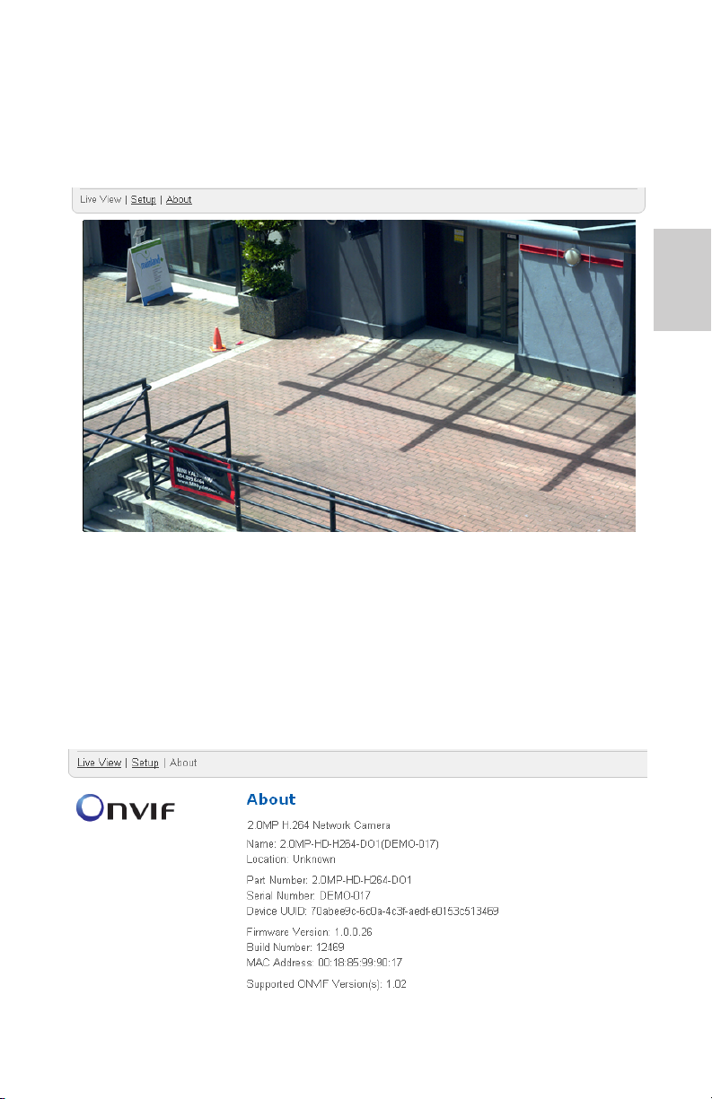
Live View
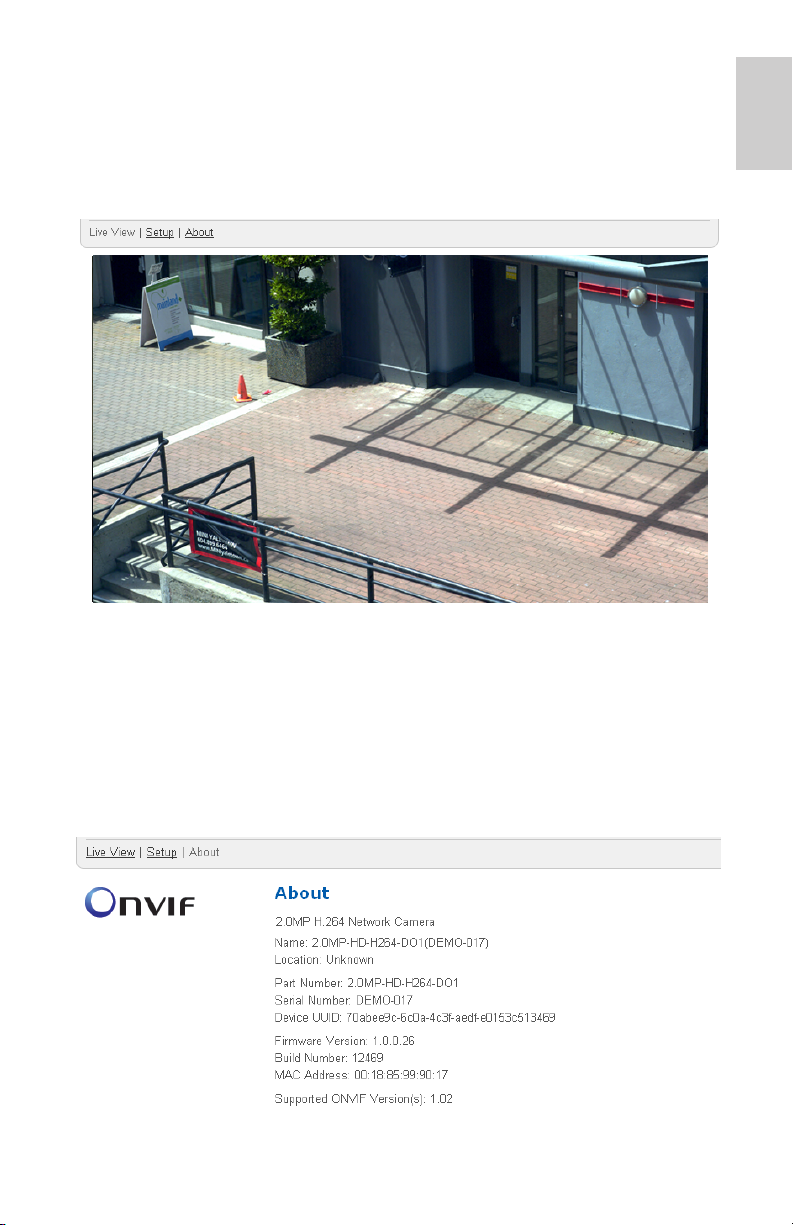
After you login, the first page you see is the camera’s Live View.
Live View contains an image panel that displays the camera’s live
video stream.
The menu links at the top left corner takes you to each of the pages
in the web interface. Click Live View any time to return to this
page.
English
About
The About page displays detailed information about the camera.
3
Page 8
English
Setup
NOTE: Some or all Setup pages may not be displayed if you do not
have the required user permissions.
The Avigilon camera’s default settings allow you to use the camera
immediately after installation. If you have special requirements, you
can customize the camera settings through the camera web
interface.
A Restore Default button is available on each Setup page to allow
you to restore the camera back to its original settings.
Be aware that some of the settings are only available through the
camera web interface and can not be changed in the network video
management software.
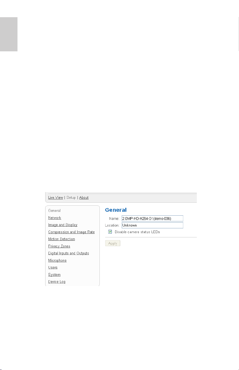
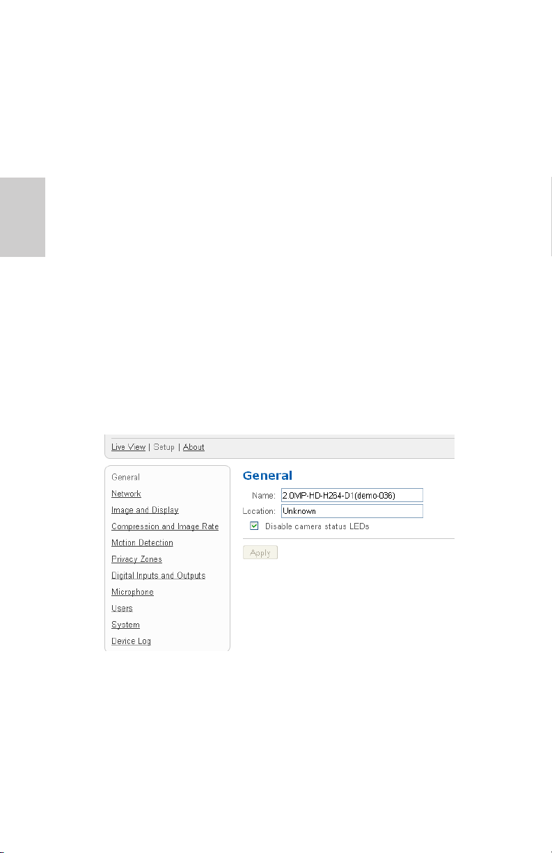
General
When you select the Setup link, the first page you see is the
General page. The General page allows you to set the camera’s
identity.
1. In the Name field, give the camera a meaningful name to
help you identify the camera.
2. In the Location field, describe the camera’s location.
3. Select the Disable camera status LEDs check box to
disable the LEDs located on the back of the camera.
4. Click Apply.
4
Page 9

Network
On the Network page, you can change how the camera connects to
the server network and choose how the camera keeps time.
NOTE: You can only set the HTTPS port, the RTSP port, and the
NTP Server in the camera web interface.
1. In the Address and Hostname area, select how the camera
obtains an IP address:
• Obtain an IP address automatically: select this
option for the camera to connect to the network
through an automatically assigned IP address.
The camera will try to obtain an address from a DHCP
server. If it can not, the camera will default to
addresses in the 169.254.x.x range.
• Use the following IP address: select this option to
manually assign a static IP address for the camera.
Enter the IP Address, Subnet Mask, and Default
Gateway you want the camera to use.
2. In the Control Ports area, you can specify which control
ports are used to access the camera. You can enter any
port number between 1 and 65534. The default port
numbers are:
English
• HTTP Port: 80
• HTTPS Port: 443
• RTSP Port: 554
3. In the NTP Server area, select how the camera keeps time.
The camera does not have an internal clock so it uses a
Network Time Protocol (NTP) server to keep time.
• Obtain NTP server via DHCP: select this option for
the camera to automatically use the same NTP server
as the rest of the network.
• Use the following NTP server: select this option to
manually set which NTP server the camera will use.
4. Click Apply when you are done.
5
Page 10
English
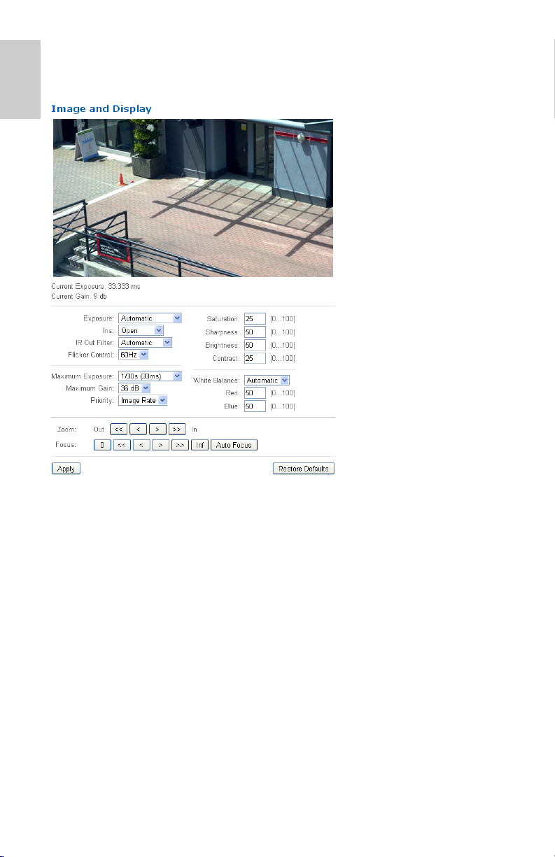
Image and Display
On the Image and
Display page, you can
control the camera’s
video display settings.
The Image and Display
page includes an
image panel that
displays the camera’s
live video stream.
When you click Apply
to save your changes,
the video stream is
updated.
Avigilon cameras have
electronic zoom and
focus controls, so you
can set the camera’s
zoom and focus
through this page as
well.
1. Use the Zoom controls to adjust the camera’s zoom
position.
2. If the camera has a built-in auto focus feature, you can
select the Continuous Focus option to enable the camera
to focus itself whenever the scene changes.
3. To manually focus the camera, select Open in the Iris drop
down list then use the Focus buttons to focus the camera.
The left arrow buttons focus the camera towards Zero (0),
and the right arrow buttons focus the camera towards
Infinity. Click the Auto Focus button to enable the camera
to automatically focus once.
NOTE: Once the focus is manually set, it will not change.
6
Page 11
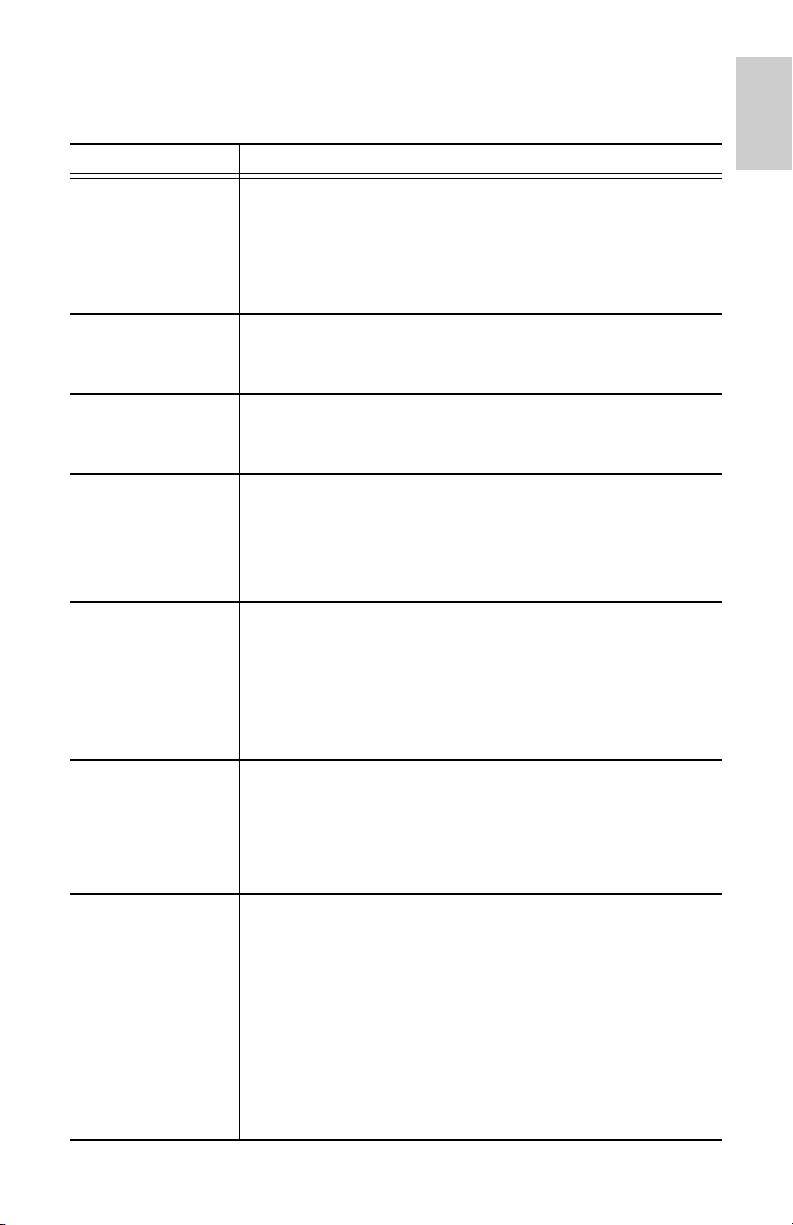
4. To adjust the video image, make changes to any of the
following settings as required.
Option Description
Exposure
Iris
IR Cut Filter
Flicker Control
Maximum
Exposure
Maximum Gain
Priority You can set Image Rate or Exposure as the
You can allow the camera to control the exposure by
selecting
exposure rate.
Automatic, or you can set a specific
NOTE: Increasing the manual exposure time may
affect the image rate.
You can allow the camera to control the iris by
selecting Automatic, or you can manually set it to
Open or Closed.
You can allow the camera to control the infrared cut
filter by selecting Automatic, or set the camera to
Color or Monochrome mode.
If your video image flickers because of the fluorescent
lights around the camera, you can reduce the effects
of the flicker by setting the Flicker Control to the same
frequency as your lights. Generally, Europe is 50Hz
and North America is 60Hz.
You can limit the automatic exposure setting by
selecting a maximum exposure level.
By setting a maximum exposure level for low light
situations, you can control the camera's exposure
time to let in the maximum amount of light without
creating blurry images.
You can limit the automatic gain setting by selecting a
maximum gain level.
By setting the maximum gain level for low light
situations, you can maximize the detail of an image
without creating excessive noise in the images.
priority.
English
When set to Image Rate, the camera will maintain
the set image rate as the priority and will not adjust
the exposure beyond what can be recorded for the set
image rate.
When set to Exposure the camera will maintain the
exposure setting as the priority, and will override the
set image rate to achieve the best image possible.
7
Page 12
English
Option Description
Saturation
Sharpness
Brightness
Contrast
White Balance
You can adjust the video’s color saturation by entering
a percentage number. 0 creates a black and white
image, while 100 creates intense color images.
You can adjust the video’s sharpness by entering a
percentage number. 0 applies the least amount of
sharpening, while 100 applies the most sharpening to
make the edges of objects more visible.
You can adjust the video’s brightness by entering a
percentage number. 0 creates a dark image, while
100 creates a light-filled image.
You can adjust the video’s contrast by entering a
percentage number. 0 applies the least amount of
contrast, while 100 applies the most contrast.
You can control the white balance settings to adjust for
differences in light.
You can allow the camera to control the white balance
by selecting Automatic, or select Custom and
manually set the Red and Blue settings.
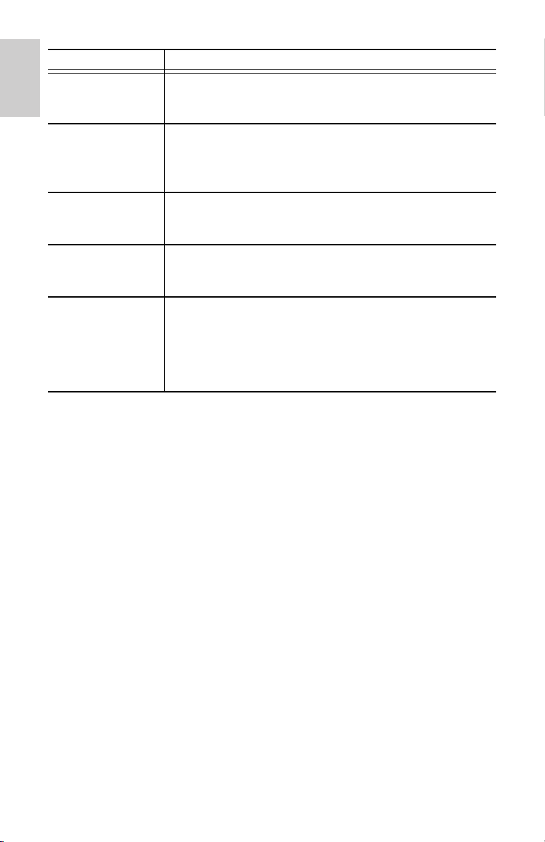
Compression and Image Rate
On the Compression and Image Rate page, you can change the
camera’s compression and image quality settings for sending video
over the network.
To enable easy access and lower bandwidth usage, the camera
web interface only displays video in JPEG format. The settings on
this page only affect the video transmitted to the network video
management software. The compression format for the camera’s
Live View in the web interface cannot be changed.
NOTE: You can only set the RTSP stream settings in the camera
web interface.
8
Page 13
1. In the Format drop down list, select the preferred streaming
format for displaying the camera video in the network video
management software.
2. In the Image Rate field, enter a number between 1-30 to
indicate how many images per second you want the
camera to stream over the network.
3. In the Quality drop down list, select the desired image
quality level.
Image quality setting of 1 will produce the highest quality
video and require the most bandwidth.
English
4. In the Max Bitrate field, enter the maximum bandwidth the
camera can use. You can enter any number between 25612000 kbps.
5. In the Resolution drop down list, select the preferred
image resolution.
6. In the Keyframe Interval field, enter the number of frames
between each keyframe. You can enter any number
between 2-64.
7. Click Apply to save your changes.
9
Page 14

English
Configuring RTSP Stream URI
In the Compression and Image Rate page, you can also configure
the camera’s real time streaming protocol (RTSP). The RTSP
Stream URI allows you to watch the camera’s live video stream
from any application that supports viewing RTSP streams,
including many video players.
1. To set the protocol, select either Unicast or Multicast in
the RTSP Stream URI area then click Apply.
2. To watch the camera’s live video stream from an external
video player, click Generate RTSP Stream URI.
a. Copy and paste the generated address in to your video
player. DO NOT open the live video stream yet.
b. Add your username and password to the beginning of
the address. Use this format:
http://<username>:<password>@<
URI
>/
For example:
defaultPrimary?streamType=u
c. Open the live video stream.
rtsp://admin:admin@192.168.1.79/
generated RTSP Stream
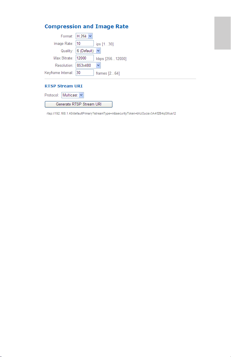
Motion Detection
On the Motion Detection page, you can define the green motion
detection areas in the camera’s field of view. Motion detection is
ignored in areas not highlighted in green.
If motion is detected anywhere in the camera’s field of view, the
motion indicator on the top right corner turns red. To help you
define motion sensitivity and threshold, motion is also highlighted
in red in the image panel.
10
Page 15
1. To set the motion detection area, perform one of the
following:
• Click Set All to set the motion detection area to span
the whole video image.
• Click Clear All to remove all motion detection areas on
the video image.
• Click anywhere on the video image to add or remove a
specific motion detection area.
2. In the Sensitivity field, enter a percentage number to
define how much each pixel must change before it is
considered in motion.
English
The higher the sensitivity, the smaller the amount of pixel
change is required before motion is detected.
3. In the Threshold field, enter a percentage number to define
how many pixels must change before the image is
considered to have motion.
The higher the threshold, the higher the number of pixels
must change before the image is considered to have
motion.
4. Click Apply to save your changes.
11
Page 16
English
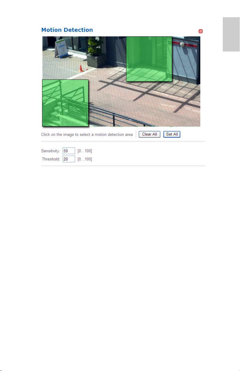
Privacy Zones
On the Privacy Zones page, you can set privacy zones in the
camera’s field of view to block out areas that you do not want to see
or record.
Adding Privacy Zones
1. Select the Privacy Zone 1 check box to create your first
privacy zone.
2. Enter the privacy zone’s size and position in the camera’s
field of view:
The size and position range is displayed beside each option
and changes to meet the privacy zone size limitations.
Enter the Width first, then see what the other options
update to before entering your other requirements.
• X: horizontal position. 0 places the privacy zone at the
far left.
• Y: vertical position. 0 places the privacy zone at the
top.
• Width: the width of the privacy zone in pixels.
• Height: the height of the privacy zone in pixels.
12
Page 17

3. Click Apply to save your changes. The privacy zone is
added to the image panel.
4. To add a second privacy zone, select the Privacy Zone 2
check box now.
5. Enter the privacy zone’s size and position in the camera’s
field of view then click Apply to save your changes.
6. To add a third privacy zone, select the Privacy Zone 3
check box now.
7. Enter the privacy zone’s size and position in the camera’s
field of view then click Apply to save your changes.
Removing Privacy Zones
To remove a privacy zone, you must clear the Privacy Zone # check
box. The check boxes can only be cleared in order, you can not
remove Privacy Zone 2 without removing Privacy Zone 3. Click
Apply to save your changes.
Digital Inputs and Outputs
On the Digital Inputs and Outputs page, you can set up the external
input and output devices that are connected to the camera.
English
1. In the Digital Inputs area, name the digital input and select
the digital input’s circuit state.
2. In the Digital Outputs area, name the digital output and
select the digital output’s circuit state.
13
Page 18
English
3. In the Digital Outputs Duration field, enter how long the
digital output is active for when triggered. You can enter any
number between 100-3,600,000 milliseconds.
4. Click Trigger to manually trigger the digital output from the
web interface.
5. Click Apply to save your changes.
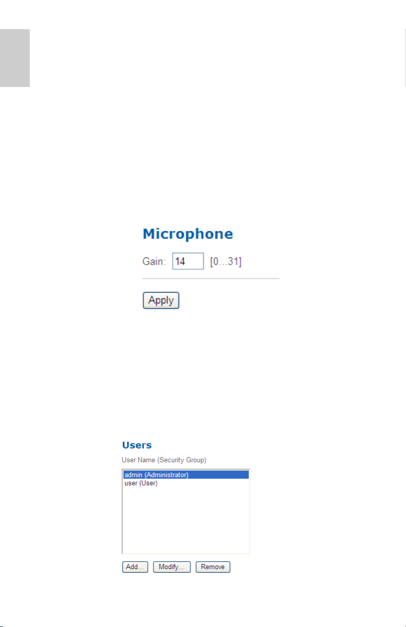
Microphone
If a microphone is connected to the camera, you can adjust the
gain on the Microphone page. The higher the gain setting, the
higher the microphone volume.
• Enter a number between 0-31 to set the microphone gain
then click Apply.
Users
On the Users page, you can add new users, edit existing users,
and change passwords.
14
Page 19

Adding a User
1. On the Users page, click Add....
2. On the Add User page, enter a username and password for
the new user.
3. In the Security Group drop down list, select the access
permissions available to this new user.
• Administrator: full access to all the available features
in the camera web interface.
• Operator: limited access to the Setup features. You
can only access the Image and Display page,
Compression and Image Rate page, Motion Detection
page, Digital Inputs and Outputs page, and the
Microphone page.
• User: can not access the Setup features, but can see
the camera’s Live View and About page.
4. Click Apply to add the user.
Editing Users and Passwords
1. On the Users page, select a user from the User Name list
and click Modify.
English
2. To change the user’s password, enter a new password for
the user.
3. To change the user’s security group, select a different group
from the Security Group drop down list.
NOTE: You cannot change the security group for the admin
account.
4. Click Apply to save your changes.
15
Page 20
English
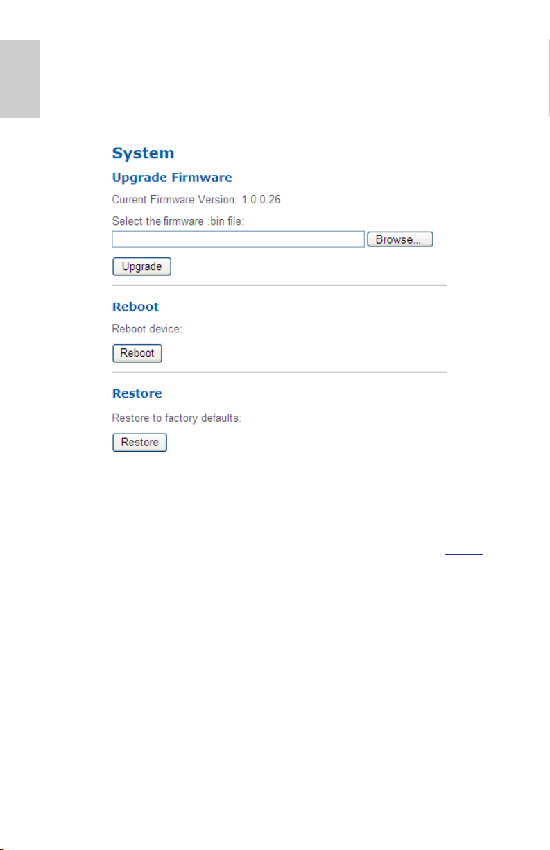
System
On the System page, you can manually upgrade the camera
firmware, reboot the camera, and restore all of the camera’s factory
default settings.
Upgrading the Camera Firmware
To manually upgrade the camera’s firmware, download the latest
version of the firmware .bin file from the Avigilon website (http://
www.avigilon.com/support/firmware) and complete the following
procedure:
1. Click Browse and locate the downloaded firmware file.
2. Click Upgrade. Wait until the camera upgrade is complete.
16
Page 21
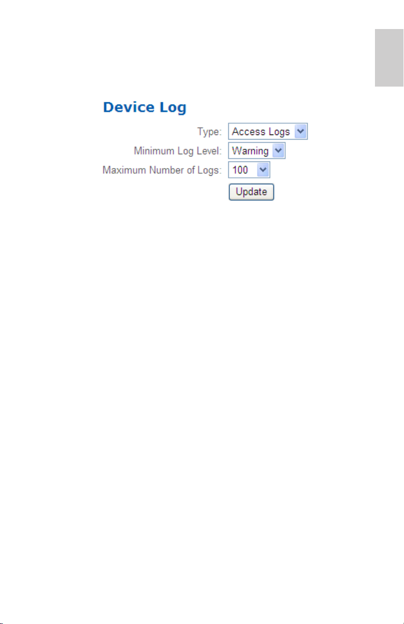
Device Log
The Device Log page allows you to view the camera’s system logs
and the camera access logs.
1. In the Type drop down list, select either Access Logs or
System Logs.
2. In the Minimum Log Level drop down list, select the log
messages you want to see.
3. In the Maximum Number of Logs drop down list, select
the number of log messages you want displayed each time.
4. Click Update. The logs are displayed below.
English
17
Page 22

Page 23

Guide de l'utilisateur
Modèles de caméra IP H.264 haute définition Avigilon :
HD-H264-B1, HD-H264-B2, HD-H264-D1, HD-H264-DC1,
HD-H264-DO1 y HD-H264-DP1
Page 24

Page 25

Copyright © 11/2/11 Avigilon. Tous droits réservés.
Aucune reproduction, distribution, publication, modification, ou incorporation de tout ou
partie de ce document n'est autorisée sans l'autorisation écrite expresse d'Avigilon. En
cas d'autorisation de reproduction, distribution, publication, modification ou incorporation
de ce document, aucune modification ou suppression du crédit de l'auteur, de la légende
des marques commerciales ou de l'avis de droits de reproduction ne devra être
effectuée. Aucune partie de ce document ne peut être reproduite, stockée sur un
système de récupération, publiée, exploitée à des fins commerciales ou transmise, sous
quelque forme que ce soit, par quelque moyen que ce soit, notamment mais sans s'y
limiter, le support électronique ou mécanique, la photocopie ou l'enregistrement, sans
l'autorisation écrite expresse d'Avigilon.
Windows et Internet Explorer sont des marques commerciales de Microsoft Inc..
Mac, Apple et Safari sont des marques commerciales d'Apple Inc..
iOS est une marque commerciale de Cisco cédée sous licence à Apple..
Opera est une marque commerciale d'Opera Software ASA.
Android est une marque commerciale de Google Inc..
Avigilon s'efforce autant que faire se peut d'identifier les propriétés faisant l'objet d'une
marque commerciale ainsi que leurs propriétaires sur cette page. Toutes les marques et
noms de produit utilisés dans ce document y figurent à des fins informatives uniquement
et peuvent constituer des marques commerciales ou des marques déposées de leurs
propriétaires respectifs.
Avigilon
Téléphone : +1.604.629.5182
Télécopie : +1.604.629.5183
http://www.avigilon.com
Révisé 11/2/11
Page 26

Tables des matières
Introduction . . . . . . . . . . . . . . . . . . . . . . . . . . . . . . . . . 1
Configuration système requise . . . . . . . . . . . . . . . . . . . . . 1
Accès à l'interface Web de la caméra . . . . . . . . . . . .2
Français
Configuration . . . . . . . . . . . . . . . . . . . . . . . . . . . . . . .4
Vue du direct . . . . . . . . . . . . . . . . . . . . . . . . . . . . . . . . . . . 3
À propos de . . . . . . . . . . . . . . . . . . . . . . . . . . . . . . . . . . . . 3
Général . . . . . . . . . . . . . . . . . . . . . . . . . . . . . . . . . . . . . . . 4
Réseau . . . . . . . . . . . . . . . . . . . . . . . . . . . . . . . . . . . . . . . 5
Image et affichage . . . . . . . . . . . . . . . . . . . . . . . . . . . . . . . 6
Débit image et vitesse compression . . . . . . . . . . . . . . . . . 9
Configuration de l'URI du flux RTSP . . . . . . . . . 10
Détection de mouvements . . . . . . . . . . . . . . . . . . . . . . . . 11
Zones privées . . . . . . . . . . . . . . . . . . . . . . . . . . . . . . . . . 12
Ajout de zones privées . . . . . . . . . . . . . . . . . . . 13
Suppression de zones privées . . . . . . . . . . . . . 13
Entrées et sorties numériques . . . . . . . . . . . . . . . . . . . . . 14
Microphone . . . . . . . . . . . . . . . . . . . . . . . . . . . . . . . . . . . 15
Utilisateurs . . . . . . . . . . . . . . . . . . . . . . . . . . . . . . . . . . . . 15
Ajout d'un utilisateur . . . . . . . . . . . . . . . . . . . . . 15
Modification des utilisateurs
et des mots de passe . . . . . . . . . . . . . . . . . . . . 16
Système . . . . . . . . . . . . . . . . . . . . . . . . . . . . . . . . . . . . . 17
Mise à niveau du microcode de la caméra . . . . 17
Journal du périphérique . . . . . . . . . . . . . . . . . . . . . . . . . . 18
Page 27

Introduction
Toutes les caméras et caméras dôme Avigilon IP H.264 haute
définition contiennent une interface Web qui vous permet d'afficher
de la vidéo en direct et de configurer l'appareil par le biais d'un
navigateur Web.
Avant d'accéder à l'interface Web de la caméra, veillez à effectuer
toutes les procédures décrites dans son guide d'installation.
Configuration système requise
Français
L'interface Web de la caméra est accessible depuis tout
équipement Windows
navigateurs suivants :
• Navigateur Windows
ultérieure
• Navigateur Mozilla® Firefox®, version 2.0.0.11 ou ultérieure
• Navigateur Opera
®
• Safari
• Navigateur Android™ 2.1(Eclair) ou ultérieur
• Navigateur Apple® iOS, version 3.2 ou ultérieure
, version 3.2.3 ou ultérieure
®
, Mac® ou mobile au moyen d'un des
®
Internet Explorer®, version 6.0.29 ou
©
, version 9.0 ou ultérieure
1
Page 28

Accès à l'interface Web de la caméra
Une fois la caméra installée, pour accéder à son interface Web,
vous devez connaître son adresse IP. L'adresse IP de la caméra se
trouve à un des emplacements suivants :
• Utilitaire d'installation de caméra Avigilon : cliquez sur le
Français
Une fois que vous disposez de l'adresse IP de la caméra, effectuez
la procédure suivante pour accéder à l'interface Web de la caméra :
bouton Connecter à caméra pour afficher les détails
relatifs à la caméra connectée.
• Logiciel Avigilon Control Center Client : ouvrez la boîte de
dialogue de configuration de la caméra pour afficher les
détails relatifs à la caméra sélectionnée.
1. Sur un ordinateur doté d'un accès à Internet, saisissez
l'adresse IP de la caméra dans un navigateur Web :
http://<Adresse IP de la caméra>/
Par exemple, http://192.168.1.40/
2. Vous êtes automatiquement invité à saisir votre nom
d'utilisateur et votre mot de passe pour accéder à la
caméra.
Le nom d'utilisateur est admin, et le mot de passe par
défaut admin. Nous vous recommandons de changer le
mot de passe par défaut dès votre première connexion.
Pour plus d'informations, reportez-vous à la section
Modification des utilisateurs et des mots de passe en
page 16.
REMARQUE: Vous ne pouvez modifier le mot de passe de la
caméra que dans l'interface Web. Vous ne pouvez
pas modifier le mot de passe de la caméra dans le
logiciel de gestion des vidéos en réseau (NVMS).
2
Page 29
Vue du direct
Une fois connecté à la caméra, la première page qui s'affiche
présente la vue du direct de la caméra. La vue du direct contient un
panneau d'images. Il affiche le flux vidéo de la caméra.
Les liens du menu du coin supérieur droit ouvre chacune des
pages de l'interface Web. Pour revenir à la présente page à tout
moment, cliquez sur Vue du direct.
Français
À propos de
La page À propos de affiche des informations détaillées sur la
caméra.
3
Page 30
Configuration
REMARQUE: Si vous ne disposez pas des autorisations
utilisateur requises, certaines des pages de
configuration, voire leur totalité, peuvent ne pas
s'afficher.
Les paramètres par défaut de la caméra Avigilon vous permettent
Français
d'exploiter la caméra immédiatement après son installation. Si vos
besoins sont particuliers, vous pouvez personnaliser les
paramètres de la caméra par le biais de l'interface Web.
Un bouton Restaurer valeurs par défaut est disponible sur
chaque page de configuration. Il vous permet de restaurer les
paramètres d'origine de la caméra.
N'oubliez pas que certains des paramètres ne sont accessibles
que par le biais de l'interface Web de la caméra et ne peuvent donc
pas être modifiés dans le logiciel NVMS.
Général
Lorsque vous sélectionnez le lien Configuration, la page Général
s'affiche en premier. La page Général vous permet de définir
l'identité de la caméra.
1. Dans le champ Nom, donnez à la caméra un nom descriptif
qui facilitera son identification.
2. Dans le champ Emplacement, décrivez l'emplacement de
la caméra.
3. Cochez la case Désactiver LED de statut de caméra afin
de désactiver les diodes, ou LED (Light Emitting Diode),
situées à l'arrière de la caméra.
4. Cliquez sur Appliquer.
4
Page 31

Réseau
La page Réseau vous permet de modifier le mode de connexion de
la caméra au réseau sur lequel est installé le serveur ainsi que la
manière dont la caméra conserve l'heure.
REMARQUE: L'interface Web de la caméra vous permet
également définir le port HTTPS, le port RTSP et le
serveur NTP.
1. Dans les zones Adresse et Nom d'hôte, sélectionnez la
manière dont la caméra obtient une adresse IP :
• Obtenir automatiquement une adresse IP : activez
cette option pour que la caméra se connecte au réseau
par le biais d'une adresse IP affectée automatiquement.
La caméra tente d'obtenir une adresse auprès d'un
serveur DHCP. Si elle n'y parvient pas, la caméra
utilise par défaut une adresse de la plage 169.254.x.x.
• Utiliser adresse IP suivante : activez cette option
pour affecter manuellement une adresse IP statique à
la caméra.
Saisissez les Adresse IP, Masque de sous-réseau et
Passerelle par défaut que vous souhaitez utiliser pour
la caméra.
2. La zone Ports de contrôle vous permet de spécifier les
ports de contrôle utilisés pour accéder à la caméra. Vous
pouvez saisir n'importe quel numéro de port entre 1 et
65534. Les numéros de port par défaut sont les suivants :
• Port HTTP : 80
• Port HTTPS : 443
• Port RTSP : 554
3. La zone Serveur NTP vous permet de sélectionner la manière
dont la caméra conserve l'heure. La caméra ne dispose
d'aucune horloge interne. Aussi, elle recourt à un serveur NTP
(Network Time Protocol) pour conserver l'heure.
• Obtenir un serveur NTP via DHCP : activez cette
option afin que la caméra utilise automatiquement le
même serveur NTP que le reste du réseau.
• Utiliser le serveur NTP suivant : activez cette option
pour définir manuellement le serveur NTP que la
caméra utilisera.
4. Cliquez sur Appliquer une fois que vous avez terminé.
Français
5
Page 32

Image et affichage
Français
La page Image et
affichage vous permet de
contrôler les paramètres
d'affichage vidéo de la
caméra.
La page Image et
affichage comprend un
panneau d'images. Il
affiche le flux vidéo de la
caméra. Lorsque vous
cliquez sur Appliquer
pour enregistrer vos
modifications, le flux
vidéo est mis à jour.
Les caméras Avigilon
sont dotées de
commandes de zoom et
de mise au point
électriques. Elles vous
permettent de régler le
zoom et la mise au point
depuis cette page.
1. Utilisez les commandes de zoom pour régler le positionnement
du zoom de la caméra.
2. Si la caméra dispose d'une fonction de mise au point
automatique (autofocus) intégrée, activez l'option Mise au point
continue
mise au point lorsque la scène change.
3. Pour régler manuellement la mise au point de la caméra,
sélectionnez Ouvrir dans la liste déroulante Diaphragme, puis
utilisez les boutons Mise au point pour effectuer le réglage.
Les boutons fléchés gauche effectuent la mise au point de la
caméra vers la valeur zéro (0), les boutons fléchés droits vers la
valeur infinie. Cliquez sur le bouton Autofocus pour que la
caméra effectue automatiquement la mise au point une fois.
pour permettre à la caméra d'effectuer elle-même la
REMARQUE: Une fois la mise au point effectuée manuellement,
elle ne change plus.
6
Page 33

4. Pour régler l'image vidéo, modifiez un des paramètres
suivants selon les besoins.
Option Description
Exposition Lorsque vous sélectionnez Automatique, la
caméra peut contrôler l'exposition. Vous pouvez
également définir un taux d'exposition spécifique.
REMARQUE: Accroître la durée d'exposition
manuelle peut affecter le débit
d'images.
Diaphragme : Lorsque vous sélectionnez Automatique, la
caméra peut contrôler le diaphragme. Vous
pouvez également affecter manuellement à ce
réglage la valeur Ouvert ou Fermé.
Filtre de
coupure IR
Contrôle du
scintillement
Exposition
maximum
Gain maximum Vous pouvez restreindre la valeur du paramètre
Lorsque vous sélectionnez Automatique, la
caméra peut contrôler le filtre de coupure IR.
Vous pouvez également affecter à la caméra le
mode Couleur ou Monochrome.
Si votre image vidéo scintille du fait de lampes
fluorescentes placées autour de la caméra,
diminuez l'effet de scintillement en appliquant au
Contrôle du scintillement la même fréquence
qu'à vos lampes. Cette fréquence est
généralement de 50 Hz en Europe et de 60 Hz
en Amérique du Nord.
Vous pouvez restreindre la valeur du paramètre
d'exposition automatique en sélectionnant un
niveau d'exposition maximal.
En fixant un niveau d'exposition maximal pour les
situations de faible luminosité, vous contrôlez la
durée d'exposition de la caméra de sorte à
permettre le captage de la quantité maximale de
lumière sans créer d'images floues.
de gain automatique en sélectionnant un niveau
de gain maximal.
En fixant un niveau de gain maximal pour les
situations de faible luminosité, vous optimisez le
détail de l'image sans générer de bruit excessif.
Français
7
Page 34

Option Description
Priorité Vous pouvez définir le paramètre Débit
d'images ou Exposition en tant que priorité.
Lorsque la priorité porte sur le Débit d'images,
la caméra préserve le débit d'images défini en
tant que priorité et ne règle pas l'exposition au-
Français
Saturation Vous pouvez régler la saturation chromatique de
Netteté Vous pouvez régler la netteté de la vidéo en
Luminosité Vous pouvez régler la luminosité de la vidéo en
Contraste Vous pouvez régler le contraste de la vidéo en
Balance des
blancs
delà de ce que le débit d'images défini est
capable d'enregistrer.
Lorsque la priorité port sur l'Exposition, la
caméra préserve le niveau d'exposition défini en
tant que priorité sans dépasser le débit d'images
défini pour atteindre la meilleure qualité d'image
possible.
la vidéo en saisissant une valeur en
pourcentage. 0 crée une image en noir et blanc,
100 des images en couleurs intenses.
saisissant une valeur en pourcentage. 0 applique
la netteté la plus faible aux contours des objets
pour les rendre plus visibles, 100 la netteté la
plus élevée.
saisissant une valeur en pourcentage. 0 crée une
image sombre, tandis que 100 crée une image
illuminée.
saisissant une valeur en pourcentage. 0 applique
le contraste minimal, tandis que 100 applique le
contraste maximal.
Vous pouvez contrôler la balance des blancs
pour adapter la caméra aux différences de
lumière.
Lorsque vous sélectionnez Automatique, la
caméra peut contrôler la balance des blancs.
Vous pouvez également sélectionner
Personnalisé et régler manuellement les
paramètres de Rouge et de Bleu.
8
Page 35

Débit image et vitesse compression
La page Débit image et vitesse compression vous permet de
modifier les paramètres de compression et de qualité d'image pour
l'acheminement de flux vidéo sur le réseau.
Pour faciliter l'accès et diminuer l'usage de la bande passante,
l'interface Web de la caméra affiche le flux vidéo uniquement au
format JPEG. Les paramètres de cette page affectent uniquement
la vidéo transmise au logiciel de gestion vidéo en réseau, ou
NVMS (Network Video Management Software). Le format de
compression de la vue du direct de la caméra accessible dans
l'interface Web ne peut pas être modifié.
REMARQUE: L'interface Web de la caméra ne permet de modifier
que les paramètres de flux RTSP.
Français
1. Dans la liste déroulante Format, sélectionnez le format de
gestion de flux retenu pour l'affichage de la vidéo de la
caméra au niveau du NVMS.
2. Dans le champ Débit d'images, saisissez une valeur entre
1 et 30 pour spécifier le nombre d'images par seconde que
vous souhaitez voir acheminé en flux par la caméra sur le
réseau.
3. Dans la liste déroulante Qualité, sélectionnez le niveau de
qualité d'image souhaité.
Une valeur de qualité d'image de 1 produira la qualité vidéo
la plus élevée et sollicitera le plus de bande passante.
9
Page 36

4. Dans le champ Débit maximal en bits, saisissez la bande
passante maximale que la caméra peut utiliser. Vous
pouvez saisir n'importe quelle valeur entre 256 et 12
000 kbits/s.
5. Dans la liste déroulante Résolution, sélectionnez la
résolution d'image souhaitée.
Français
6. Dans le champ Intervalle images clés, saisissez le
nombre d'images présentes entre les images clés. Vous
pouvez saisir n'importe quelle valeur entre 2 et 64.
7. Cliquez sur Appliquer pour enregistrer vos modifications.
Configuration de l'URI du flux RTSP
La page Débit image et vitesse compression vous permet
également de configurer le protocole de gestion de flux en temps
réel RTSP (Real Time Streaming Protocol) de la caméra. L'URI de
gestion de flux RTSP vous permet de visionner le flux vidéo de la
caméra en direct depuis n'importe quelle application qui prend en
charge les flux RTSP, dont un grand nombre de lecteurs vidéo.
1. Pour définir le protocole, sélectionnez soit Unicast, soit
Multicast dans la zone URI de flux RTSP, puis cliquez sur
Appliquer.
2. Pour visionner le flux vidéo direct de la caméra depuis un
lecteur vidéo externe, cliquez sur Générer une URI de flux
RTSP.
a. Copiez l'adresse générée, puis collez-la dans votre
lecteur vidéo. N'OUVREZ PAS le flux vidéo direct pour
le moment.
10
b. Ajoutez votre nom d'utilisateur et votre mot de passe
au début de l'adresse. Utilisez le format suivant :
http://<nom_utilisateur>:<mot_de_passe>@<
RTSP générée
Par exemple :
defaultPrimary?streamType=u
>/
rtsp://admin:admin@192.168.1.79/
URI de flux
c. Ouvrez le flux vidéo en direct.
Page 37

Détection de mouvements
La page Détection de mouvements vous permet de définir les
zones de détection de mouvements vertes dans le champ de vision
de la caméra. La détection de mouvements n'est pas prise en
compte dans les zones qui ne sont pas mises en évidence en vert.
Si un mouvement est détecté dans le champ de vision de la
caméra, l'indicateur de mouvement placé dans le coin supérieur
droit devient rouge. Pour faciliter la définition du seuil et de la
sensibilité de mouvement, le mouvement est, lui aussi, mis en
évidence en rouge dans le volet d'image.
Français
1. Pour définir la zone de détection de mouvement, procédez
d'une des manières suivantes :
• Cliquez sur Définir tout pour configurer la zone de
détection de mouvements afin qu'elle s'étende à
l'intégralité de l'image vidéo.
• Cliquez sur Tout vider pour éliminer toutes les zones
de détection de mouvements de l'image.
• Cliquez sur l'image vidéo pour ajouter ou retirer une
zone de détection de mouvements spécifique.
2. Dans le champ Sensibilité, saisissez un pourcentage afin
de définir la proportion de changement de chaque pixel
11
Page 38

pour que l'image soit considérée comme l'objet d'un
mouvement.
Plus la sensibilité est élevée, plus la proportion de
changement de pixels requise avant détection de
mouvement est faible.
3. Dans le champ Seuil, saisissez un pourcentage afin de
définir le nombre de pixels qui doivent changer avant que
Français
l'image soit considérée comme l'objet d'un mouvement.
Plus le seuil est élevé, plus le nombre de pixels nécessaire
pour que l'image soit considérée comme l'objet d'un
mouvement est élevé.
4. Cliquez sur Appliquer pour enregistrer vos modifications.
Zones privées
La page Zones privées permet de définir des zones privées dans le
champ de vision de la caméra afin de bloquer les secteurs que
vous ne souhaitez ni visionner, ni enregistrer.
12
Page 39

Ajout de zones privées
1. Activez l'option Zone privée 1 pour créer votre première
zone privée.
2. Saisissez la taille et l'emplacement de la zone privée dans
le champ de vision de la caméra :
La plage de taille et d'emplacement s'affiche en regard de
chaque option et change pour s'adapter aux limites de taille
de la zone privée. Saisissez d'abord une Largeur, puis
inspectez la mise à jour des autres options avant de saisir
d'autres paramètres.
• X : position horizontale. La valeur 0 place la zone
privée à l'extrême gauche.
• Y : position verticale. La valeur 0 place la zone privée
en haut.
• Largeur : largeur de la zone privée en pixels.
• Hauteur : hauteur de la zone privée en pixels.
3. Cliquez sur Appliquer pour enregistrer vos modifications.
La zone privée est ajoutée au volet d'image.
4. Pour ajouter une deuxième zone privée, activez à présent
l'option Zone privée 2.
Français
5. Saisissez la taille et l'emplacement de la zone privée dans
le champ de vision de la caméra, puis cliquez sur
Appliquer pour enregistrer vos modifications.
6. Pour ajouter une troisième zone privée, activez à présent
l'option Zone privée 3.
7. Saisissez la taille et l'emplacement de la zone privée dans
le champ de vision de la caméra, puis cliquez sur
Appliquer pour enregistrer vos modifications.
Suppression de zones privées
Pour supprimer une zone privée, vous devez désactiver la case à
cocher correspondante. Les cases à cocher se désactivent
uniquement dans l'ordre. Ainsi, vous ne pouvez pas supprimer la
zone privée 2 sans supprimer la 3. Cliquez sur Appliquer pour
enregistrer vos modifications.
13
Page 40

Entrées et sorties numériques
La page Entrées et sorties numériques vous permet de configurer
les dispositifs d'entrée et de sortie externes connectés à la
caméra.
Français
1. Dans la zone Entrées numériques, nommez l'entrée
numérique, puis sélectionnez l'état de circuit pour celle-ci.
2. Dans la zone Sorties numériques, nommez la sortie
numérique, puis sélectionnez l'état de circuit pour celle-ci.
3. Dans le champ Durée de la sortie numérique, saisissez la
durée d'activité de la sortie numérique une fois celle-ci
déclenchée. Vous pouvez saisir n'importe quelle valeur
entre 100 et 3 600 000 millisecondes.
4. Cliquez sur Déclencher pour déclencher manuellement la
sortie numérique à partir de l'interface Web.
5. Cliquez sur Appliquer pour enregistrer vos modifications.
14
Page 41

Microphone
Si un micro est connecté à la caméra, vous pouvez en régler le
gain dans la page Microphone. Plus la valeur de gain est élevée,
plus le volume du micro sera élevé.
• Saisissez une valeur entre 0 et 31 pour régler le gain du
micro, puis cliquez sur Appliquer.
Utilisateurs
La page Utilisateurs vous permet d'ajouter ou de modifier des
utilisateurs, et de changer les mots de passe.
Français
Ajout d'un utilisateur
1. Dans la page Utilisateurs, cliquez sur Ajouter....
2. Dans la page Ajouter un utilisateur, saisissez un nom
d'utilisateur et un mot de passe pour le nouvel utilisateur.
15
Page 42

3. Dans la liste déroulante Groupe de sécurité, sélectionnez
les autorisations d'accès disponibles pour ce nouvel
utilisateur.
• Administrateur : accès intégral à toutes les fonctions
disponibles dans l'interface Web de la caméra.
• Opérateur : accès restreint aux fonctions de
Français
4. Cliquez sur Appliquer pour ajouter l'utilisateur.
configuration. Vous avez accès uniquement aux pages
Image et affichage, Débit image et vitesse
compression, Détection de mouvements, Entrées et
sorties numériques et Microphone.
• Utilisateur : aucun accès aux fonctions de
configuration, mais l'utilisateur peut afficher les pages
Vue direct et À propos de de la caméra.
Modification des utilisateurs et des mots de passe
1. Dans la page Utilisateurs, sélectionnez un utilisateur dans
la liste Nom d'utilisateur, puis cliquez sur Modifier.
2. Pour modifier le mot de passe de l'utilisateur, saisissez un
nouveau mot de passe pour celui-ci.
3. Pour modifier le groupe de sécurité de l'utilisateur,
sélectionnez un groupe différent dans la liste déroulante
Groupe de sécurité.
REMARQUE: Vous ne pouvez pas modifier le groupe de sécurité
du compte d'administrateur.
4. Cliquez sur Appliquer pour enregistrer vos modifications.
16
Page 43

Système
La page Système vous permet de mettre manuellement à niveau le
microcode de la caméra, de réinitialiser celle-ci et de restaurer tous
ses paramètres par défaut d'usine.
Français
Mise à niveau du microcode de la caméra
Pour mettre manuellement à niveau le microcode de la caméra,
téléchargez la version la plus récente du fichier .bin du microcode
depuis le site Web d'Avigilon (http://www.avigilon.com/support/
firmware) puis effectuez la procédure suivante :
1. Cliquez sur Parcourir puis localisez le fichier de microcode
téléchargé.
2. Cliquez sur Mettre à niveau. Attendez que la mise à niveau
de la caméra soit terminée.
17
Page 44

Journal du périphérique
La page Journal du périphérique vous permet d'afficher les
journaux système et d'accès de la caméra.
Français
1. Dans la liste déroulante Type, sélectionnez soit les
Journaux d'accès, soit les Journaux système.
2. Dans la liste déroulante Niveau de journalisation
minimal, sélectionnez les messages de journal que vous
souhaitez afficher.
3. Dans la liste déroulante Nombre de journaux maximal,
sélectionnez le nombre de messages de journal que vous
souhaitez afficher à chaque fois.
4. Cliquez sur Mettre à jour. Les journaux s'affichent audessous.
18
Page 45

Page 46

Page 47

Guía del usuario
Cámara IP H.264 de alta definición de Avigilon modelos:
HD-H264-B1, HD-H264-B2, HD-H264-D1, HD-H264-DC1,
HD-H264-DO1 y HD-H264-DP1
Page 48

Copyright © 11/8/11 Avigilon. Reservados todos los derechos.
No se permite la copia, distribución, publicación, modificación o incorporación de este
documento, total o parcial, sin el permiso expreso por escrito de Avigilon. En el caso de
que se permita la copia, distribución, publicación, modificación o incorporación de este
documento, no se realizará ningún cambio ni eliminación de la atribución de autoría,
leyenda de marca comercial o aviso de copyright. Ninguna parte de este documento
podrá ser reproducida, almacenada en un sistema de recuperación, publicada, usada
para explotación comercial ni transmitida, de ninguna forma y por ningún medio,
electrónico, mecánico, fotocopia, grabación y otros medios, sin la autorización expresa
por escrito de Avigilon.
Windows e Internet Explorer son marcas comerciales de Microsoft Inc.
Mac, Apple y Safari son marcas comerciales de Apple Inc.
iOS es una marca comercial de Cisco autorizada a Apple.
Opera es una marca comercial de Opera Software ASA.
Android es una marca comercial de Google Inc.
Avigilon ha hecho todo lo posible para identificar las propiedades y propietarios con
marca comercial en esta página. Todas las marcas y nombres de productos utilizados
en este documento solo son con fines de identificación y pueden ser marcas
comerciales o marcas comerciales registradas de sus empresas respectivas.
Avigilon
Tel +1.604.629.5182
Fax +1.604.629.5183
http://www.avigilon.com
Revisado 11/8/11
Page 49

Tabla de Contenidos
Introducción . . . . . . . . . . . . . . . . . . . . . . . . . . . . . . . . 1
Requisitos del sistema . . . . . . . . . . . . . . . . . . . . . . . . . . . 1
Acceso a la interfaz web de la cámara . . . . . . . . . . . 2
Live View . . . . . . . . . . . . . . . . . . . . . . . . . . . . . . . . . . . . . . 3
Acerca de . . . . . . . . . . . . . . . . . . . . . . . . . . . . . . . . . . . . . 3
Configuración . . . . . . . . . . . . . . . . . . . . . . . . . . . . . . . 4
General . . . . . . . . . . . . . . . . . . . . . . . . . . . . . . . . . . . . . . . 4
Red . . . . . . . . . . . . . . . . . . . . . . . . . . . . . . . . . . . . . . . . . . 5
Imagen y visualización . . . . . . . . . . . . . . . . . . . . . . . . . . . 6
Compresión y frecuencia de actualización de la imagen . 8
Configuración de la URI de flujo RTSP . . . . . . . . 9
Detección de movimiento . . . . . . . . . . . . . . . . . . . . . . . . 10
Zonas de privacidad . . . . . . . . . . . . . . . . . . . . . . . . . . . . 11
Adición de zonas de privacidad . . . . . . . . . . . . 12
Supresión de zonas de privacidad . . . . . . . . . . 12
Entradas y salidas digitales . . . . . . . . . . . . . . . . . . . . . . . 13
Micrófono . . . . . . . . . . . . . . . . . . . . . . . . . . . . . . . . . . . . . 14
Usuarios . . . . . . . . . . . . . . . . . . . . . . . . . . . . . . . . . . . . . 14
Adición de un usuario . . . . . . . . . . . . . . . . . . . . 14
Edición de usuarios y contraseñas . . . . . . . . . . 15
Sistema . . . . . . . . . . . . . . . . . . . . . . . . . . . . . . . . . . . . . . 16
Actualización del firmware de la cámara . . . . . 16
Registro de dispositivos . . . . . . . . . . . . . . . . . . . . . . . . . 17
Español
Page 50

Español
Page 51

Introducción
Todas las cámaras y cámaras domo IP H.264 de alta definición de
Avigilon contienen una interfaz web que le permite ver vídeo en
tiempo real y configurar la cámara a través de un navegador web.
Antes de acceder a la interfaz web de la cámara, asegúrese de
completar todos los procedimientos descritos en la guía de
instalación de la cámara.
Requisitos del sistema
A la interfaz web de la cámara se puede acceder desde cualquier
dispositivo Windows
navegadores siguientes:
• Navegador Windows
posterior
• Navegador Mozilla® Firefox® versión 2.0.0.11 o posterior
• Navegador Opera
• Safari
• Navegador Android™ 2.1 (Eclair) o posterior
• Navegador Apple© iOS 3.2 o posterior
®
®
, Mac® o móvil usando uno de los
®
Internet Explorer® versión 6.0.29 o
©
9.0 o posterior
3.2.3 o posterior
Español
1
Page 52

Acceso a la interfaz web de la cámara
Una vez instalada la cámara, necesita la dirección IP de la cámara
para acceder a la interfaz web. La dirección IP de la cámara se
puede encontrar en uno de los lugares siguientes:
• Avigilon Camera Installation Tool: haga clic en el botón
Conectar a cámara para ver los detalles de la cámara
conectada.
• Avigilon Control Center Client: abra el cuadro de diálogo
Configuración para ver los detalles de la cámara
seleccionada.
Cuando disponga de la dirección IP de la cámara, complete el
procedimiento siguiente para acceder a la interfaz web de la
cámara:
Español
1. En un ordenador con acceso a Internet, introduzca la
dirección IP de la cámara en un navegador web:
http://<dirección IP de la cámara>/
Por ejemplo, http://192.168.1.40/
2. Se le pedirá automáticamente que introduzca su nombre
de usuario y su contraseña para acceder a la cámara.
El nombre de usuario predeterminado de la cámara es
admin y la contraseña predeterminada es admin. Se
recomienda que cambie la contraseña predeterminada
después de su primer inicio de sesión. Para obtener más
información, consulte Edición de usuarios y contraseñas en
la página 15.
NOTA: Solo puede cambiar la contraseña de la cámara en la
interfaz web. La contraseña de la cámara no se puede
cambiar en el software de gestión de vídeo de la red.
2
Page 53

Live View
Después del inicio de sesión, la primera página que se ve es la vista
en tiempo real de la cámara. Live View contiene un panel de
imágenes que muestra el flujo de vídeo en tiempo real de la cámara.
Los enlaces de menú en la esquina superior izquierda le llevan a
cada una de las páginas de la interfaz web. Haga clic en Live View
en cualquier momento para volver a esta página.
Español
Acerca de
La página Acerca de muestra información detallada sobre la
cámara.
3
Page 54

Configuración
NOTA: Es posible que no se muestren algunas o todas las páginas
de Configuración si no tiene los permisos de usuario
requeridos.
Los ajustes predeterminados de la cámara Avigilon le permiten
usar la cámara inmediatamente después de la instalación. Si tiene
requisitos especiales, puede personalizar los ajustes de la cámara
a través de la interfaz web de la cámara.
En cada página de configuración está disponible un botón
Restaurar predeterminados que le permite restablecer la cámara
en sus ajustes originales.
Tenga presente que algunos ajustes solo están disponibles a
través de la interfaz web de la cámara y no se pueden cambiar en
Español
el software de gestión de vídeo de red.
General
Cuando selecciona el enlace Configuración, la primera página que
ve es la página General. La página General le permite configurar la
identidad de la cámara.
1. En el campo Nombre, dé a la cámara un nombre
significativo que le ayude a identificar la cámara.
2. En el campo Ubicación, describa la localización de la
cámara.
3. Seleccione la casilla Desactivar los LED de estado de la
cámara para deshabilitar los LED situados en la parte
trasera de la cámara.
4. Haga clic en Aplicar.
4
Page 55

Red
En la página Red, puede cambiar cómo se conecta la cámara a la
red del servidor y elegir cómo la cámara establece la hora.
NOTA: Solo puede establecer el puerto HTTPS, el puerto RTSP y
el servidor NTP en la interfaz web de la cámara.
1. En el área Dirección y Nombre de host, seleccione cómo
obtiene la cámara la dirección IP:
• Obtener una dirección IP automáticamente:
seleccione esta opción para que la cámara se conecte
a la red mediante una dirección IP automáticamente
asignada.
La cámara intentará obtener una dirección desde un
servidor DHCP. Si no puede, la cámara obtendrá de
manera predeterminada las direcciones en el rango
169.254.x.x.
• Usar la siguiente dirección IP: seleccione esta
opción para asignar manualmente una dirección IP
estática a la cámara.
Introduzca la Dirección IP, Máscara de subred y
Puerta de enlace predeterminada que desee que use
la cámara.
2. En el área Puerto de control, puede especificar qué
puertos de control se usan para acceder a la cámara.
Puede introducir cualquier número de puerto entre 1 y
65534. Los números de puerto predeterminados son los
siguientes:
• Puerto HTTP: 80
• Puerto HTTP: 443
• Puerto RTSP: 554
3. En el área Servidor NTP, seleccione cómo la cámara va a
establecer la hora. La cámara no tiene un reloj interno, por
tanto usa un servidor de protocolo de hora de red (NTP)
para establecer la hora.
• Obtener un servidor NTP a través de DHCP:
seleccione esta opción para que la cámara utilice
automáticamente el mismo servidor NTP que el resto
de la red.
• Usar el siguiente servidor NTP: seleccione esta
opción para establecer manualmente qué servidor
NTP utilizará la cámara.
4. Haga clic en Aplicar cuando haya finalizado.
Español
5
Page 56

Imagen y visualización
Español
En la página Imagen y
visualización, puede
controlar los ajustes de
visualización de vídeo
de la cámara.
La página Imagen y
visualización incluye un
panel de imágenes que
muestra el flujo de vídeo
en directo de la cámara.
Cuando haga clic en
Aplicar para guardar
los cambios, el flujo de
vídeo se actualiza.
Las cámaras Avigilon
disponen de controles
de enfoque y zoom
electrónicos, por tanto
puede establecer el
zoom y el enfoque de la
cámara también desde
esta página.
1. Utilice los controles de zoom para ajustar la posición de
zoom de la cámara.
2. Si la cámara tiene una función de enfoque automático
incorporada, puede seleccionar la opción Enfoque
continuo para permitir que la cámara se enfoque siempre
que cambie la escena.
3. Para enfocar manualmente la cámara, seleccione Abrir en
la lista desplegable Diafragma y después utilice los
botones Enfoque para enfocar la cámara.
Los botones de flecha izquierda enfocan la cámara hacia el
cero (0) y los botones de flecha derecha enfocan la cámara
hacia el infinito. Haga clic el botón Enfoque automático
que la cámara enfoque automáticamente una vez.
NOTA: Una vez el enfoque se establece manualmente, no
cambiará.
6
Page 57

4. Para ajustar la imagen de vídeo, realice cambios en
cualquiera de los ajustes siguientes cuando se necesite.
Opción Descripción
Exposición
Diafragma
Filtro ICR
Control de
parpadeo
Exposición
máxima
Ganancia
máxima
Prioridad
Saturación
Puede permitir que la cámara controle la exposición
seleccionando Automático o establecer una velocidad
de exposición específica.
NOTA: El aumento del tiempo de la exposición manual
puede afectar a la frecuencia de actualización
de imagen.
Puede permitir que la cámara controle el diafragma
seleccionando Automático o puede establecerlo
manualmente en Abierto o Cerrado.
Puede optar por que la cámara controle el filtro ICR
seleccionando Automático o establecer la cámara en
modo Color o Monocromo.
Si la imagen de vídeo parpadea debido a las luces
fluorescentes que rodean la cámara, puede reducir los
efectos del parpadeo estableciendo el Control de
parpadeo en la misma frecuencia que las luces. Por lo
general, Europa es 50 Hz y Norteamérica es 60 Hz.
Puede limitar el ajuste de exposición automático
seleccionando un nivel máximo de exposición.
Al establecer un nivel de exposición máximo para las
situaciones de baja luz, puede controlar el tiempo de
exposición de la cámara para permitir la máxima
cantidad de luz sin crear imágenes borrosas.
Puede limitar la ganancia máxima automática
seleccionando un nivel máximo de ganancia.
Al establecer el nivel de ganancia máxima para las
situaciones de poca luz, puede potenciar al máximo los
detalles de una imagen sin crear un ruido excesivo en
ella.
Puede establecer Frecuencia de actualización de
imagen o Exposición como prioridad.
Cuando se establece en Frecuencia de actualización
de imagen, la cámara mantendrá la frecuencia de
actualización establecida como la prioridad y no ajustará
la exposición más allá de lo que se puede grabar para la
frecuencia de actualización establecida.
Cuando se establece en Exposición la cámara
mantendrá el ajuste de exposición como prioridad y
anulará la frecuencia de actualización de la imagen
establecida para conseguir la mejor imagen posible.
Puede ajustar la saturación del color del vídeo
introduciendo un número de porcentaje. 0 crea una
imagen en blanco y negro, mientras que 100 crea
imágenes de color intensas.
Español
7
Page 58

Opción Descripción
Nitidez
Brillo
Contraste
Balance de
blancos
Español
Compresión y frecuencia de
Puede ajustar la nitidez del vídeo introduciendo un
número de porcentaje. 0 aplica la menor cantidad de
nitidez, mientras que 100 aplica la mayor nitidez para
hacer más visibles los bordes de los objetos.
Puede ajustar el brillo del vídeo introduciendo un número
de porcentaje. 0 crea una imagen oscura, mientras que
100 crea una imagen llena de luz.
Puede ajustar el contraste del vídeo introduciendo un
número de porcentaje. 0 aplica la menor cantidad de
contraste, mientras que 100 aplica el mayor contraste.
Puede controlar los ajustes de balance de blancos para
ajustar las diferencias en la luz.
Puede permitir que la cámara controle el balance de
blancos seleccionando Automático o Personalizado y
establecer manualmente los ajustes Rojo y Azul.
actualización de la imagen
En la página Compresión y frecuencia de actualización de la
imagen, puede cambiar los ajustes de calidad de imagen y
compresión de la cámara para enviar vídeo a la red.
Para permitir un fácil acceso y un menor uso de ancho de banda,
la interfaz de la cámara web solo muestra vídeo en formato JPEG.
La configuración de esta página solo afecta al vídeo transmitido
por el software de gestión de vídeo en red. No se puede cambiar el
formato de compresión para la vista en directo de la cámara en la
interfaz web.
NOTA: Solo puede establecer los ajustes del flujo RTSP en la
interfaz web de la cámara.
8
Page 59

1. En la lista desplegable Formato, seleccione el formato de
flujo preferido para mostrar el vídeo de la cámara en el
software de gestión de vídeo en red.
2. En el campo Frecuencia de actualización de imagen,
introduzca un número entre 1-30 para indicar cuántas
imágenes por segundo desea transmita la cámara por la
red.
3. En la lista desplegable Calidad, seleccione el nivel de
calidad de imagen deseado.
El ajuste de calidad de imagen de 1 producirá el vídeo de
calidad más alta y requerirá la mayor cantidad de ancho de
banda.
4. En el campo Velocidad máx. de transferencia, introduzca
el máximo ancho de banda que la cámara puede usar.
Puede introducir cualquier número entre 256-12000 kbps.
5. En la lista desplegable Resolución, seleccione la
resolución de imagen preferida.
6. En el campo Intervalo de fotograma clave, introduzca el
número de fotogramas entre cada fotograma clave. Puede
introducir cualquier número entre 2-64.
7. Haga clic en Aplicar para guardar los cambios.
Configuración de la URI de flujo RTSP
En la página Compresión y frecuencia de actualización de la
imagen, también puede configurar el protocolo de flujo en tiempo
real (RTSP) de la cámara. La URI de flujo RTSP le permite ver el
flujo de vídeo en directo de la cámara desde cualquier aplicación
que admita la visualización de flujos RTSP, como muchos
reproductores de vídeo.
1. Para establecer el protocolo, seleccione Unidifusión o
Multidifusión en el área URI de flujo RTSP y, después,
haga clic en Aplicar.
2. Para ver el flujo de vídeo en directo de la cámara desde un
reproductor de vídeo externo, haga clic en Generar URI de
flujo RTSP.
Español
9
Page 60

a. Copie y pegue la dirección generada en el reproductor
de vídeo. NO abra todavía el flujo de vídeo en directo.
b. Añada su nombre de usuario y la contraseña al
comienzo de la dirección. Utilice este formato:
http://<nombre_usuario>:<contraseña>@<
generada
Por ejemplo:
defaultPrimary?streamType=u
>/
rtsp://admin:admin@192.168.1.79/
URI de flujo RTSP
c. Abra el flujo de vídeo en tiempo real
Detección de movimiento
Español
En la página Detección de movimiento, puede definir las áreas de
detección de movimiento resaltadas en verde en el campo de
visión de la cámara. La detección de movimiento se ignora en las
áreas no resaltadas en verde.
Si el movimiento se detecta en cualquier lugar del campo de visión
de la cámara, el indicador de movimiento de la esquina superior
derecha se vuelve rojo. Para ayudarle a definir la sensibilidad y el
umbral del movimiento, este también se resalta en rojo en el panel
de imagen.
10
Page 61

1. Para establecer el área de detección del movimiento,
realice una de las opciones siguientes:
• Haga clic en Establecer todo para establecer el área
de detección de movimiento para abarcar la imagen de
vídeo completa.
• Haga clic en Borrar todos para suprimir todas las
áreas de detección de movimiento en la imagen de
vídeo.
• Haga clic en cualquier lugar de la imagen de vídeo
para añadir o suprimir un área de detección de
movimiento específica.
2. En el campo Sensibilidad, introduzca un número de
porcentaje para definir cuánto de cada píxel debe cambiar
antes de que se considere que está en movimiento.
Cuanto mayor sea la sensibilidad, menor será la cantidad
de cambio en los píxeles que se requiera antes de que se
detecte movimiento.
3. En el campo Umbral, introduzca un número de porcentaje
para definir cuántos píxeles deben cambiar antes de que la
imagen se considere que tiene movimiento.
Cuanto mayor sea el umbral, mayor será el número de
píxeles que debe cambiar antes de que la imagen se
considere que tiene movimiento.
4. Haga clic en Aplicar para guardar los cambios.
Español
Zonas de privacidad
En la página Zonas de privacidad, puede establecer zonas de
privacidad en el campo de visión de la cámara para bloquear las
áreas que no desea ver o grabar.
11
Page 62

Adición de zonas de privacidad
1. Seleccione la casilla de verificación Zona de privacidad 1
para crear su primera zona de privacidad.
2. Introduzca el tamaño y la posición de la zona de privacidad
en el campo de visión de la cámara:
El rango del tamaño y posición se muestra junto a cada
opción así como los cambios para cumplir las limitaciones
de tamaño de la zona de privacidad. Introduzca primero el
ancho; a continuación, observe qué actualizan las otras
opciones antes de introducir sus otros requisitos.
• X: posición horizontal. 0 sitúa la zona de privacidad en
el extremo izquierdo.
Español
• Y: posición vertical. 0 sitúa la zona de privacidad en la
parte superior.
• Ancho: la anchura de la zona de privacidad en píxeles.
• Alto: la altura de la zona de privacidad en píxeles.
3. Haga clic en Aplicar para guardar los cambios. La zona de
privacidad se añada al panel de imágenes.
4. Para añadir una segunda zona de privacidad, seleccione
ahora la casilla de verificación Zona de privacidad 2.
5. Introduzca el tamaño y la posición de la zona de privacidad
en el campo de visión de la cámara y, a continuación, haga
clic en Aplicar para guardar los cambios.
6. Para añadir una tercera zona de privacidad, seleccione
ahora la casilla de verificación Zona de privacidad 3.
7. Introduzca el tamaño y la posición de la zona de privacidad
en el campo de visión de la cámara y, a continuación, haga
clic en Aplicar para guardar los cambios.
Supresión de zonas de privacidad
Para suprimir una zona de privacidad, debe borrar la casilla de
verificación Zona de privacidad nº. Las casillas de verificación solo
pueden borrarse en orden, es decir, no puede suprimir la Zona de
privacidad 2 sin suprimir la Zona de privacidad 3. Haga clic en
Aplicar para guardar los cambios.
12
Page 63

Entradas y salidas digitales
En la página Entradas y salidas digitales, puede configurar los
dispositivos de salida y entrada externos que están conectados a
la cámara.
1. En el área Entradas digitales, nombre la entrada digital y
seleccione el estado del circuito de la entrada digital.
2. En el área Salidas digitales, nombre la salida digital y
seleccione el estado del circuito de la salida digital.
3. En el campo Duración de Salidas digitales, introduzca el
tiempo en que estará activa la salida digital cuando se
active. Puede introducir cualquier número entre 100-
3.600.000 milisegundos.
4. Haga clic en Disparar para activar manualmente la salida
digital en la interfaz web.
5. Haga clic en Aplicar para guardar los cambios.
Español
13
Page 64

Micrófono
Si un micrófono está conectado a la cámara, puede ajustar la
ganancia en la página Micrófono. Cuanto mayor sea la
configuración de ganancia, mayor será el volumen del micrófono.
Español
• Introduzca un número entre 0-31 para establecer la ganancia
del micrófono y, a continuación, haga clic en Aplicar.
Usuarios
En la página Usuarios, puede añadir nuevos usuarios, editar
usuarios existentes y cambiar contraseñas.
Adición de un usuario
1. En la página Usuarios, haga clic en Agregar....
2. En la página Agregar usuario, introduzca un nombre de
usuario y una contraseña para el nuevo usuario.
14
Page 65

3. En la lista desplegable Grupo de seguridad, seleccione
los permisos de acceso disponibles a este nuevo usuario.
• Administrador: acceso completo a todas las
funciones disponibles de la interfaz web de la cámara.
• Operador: acceso limitado a las funciones de
configuración. Solo puede acceder a las páginas
Imagen y visualización, Compresión y velocidad de
imagen, Detección de movimiento, Entradas y salidas
digitales y Micrófono.
• Usuario: no puede acceder a las funciones de
configuración, pero puede ver la página Live View y
Acerca de de la cámara.
4. Haga clic en Aplicar para añadir el usuario.
Edición de usuarios y contraseñas
1. En la página Usuarios, seleccione un usuario en la lista
Nombre de usuario y haga clic en Modificar.
2. Para cambiar la contraseña del usuario, introduzca una
nueva contraseña.
3. Para cambiar el grupo de seguridad del usuario, seleccione
un grupo diferente en la lista desplegable Grupo de
seguridad.
NOTA: No puede cambiar el grupo de seguridad para la cuenta de
administración.
4. Haga clic en Aplicar para guardar los cambios.
Español
15
Page 66

Sistema
En la página Sistema, puede actualizar manualmente el firmware
de la cámara, reiniciar la cámara y restaurar todos los ajustes
predeterminados de fábrica de la cámara.
Español
Actualización del firmware de la cámara
Para actualizar manualmente el firmware de la cámara, descargue
la última versión del archivo de firmware .bin en el sitio web de
Avigilon (http://www.avigilon.com/support/firmware) y complete el
procedimiento siguiente:
1. Haga clic en Examinar y localice el archivo de firmware
descargado.
2. Haga clic en Actualizar. Espere hasta que haya finalizado
la actualización de la cámara.
16
Page 67

Registro de dispositivos
La página Registro de dispositivos le permite ver los registros del
sistema de la cámara y los registros de acceso de la cámara.
1. En la lista desplegable Tipo, seleccione Registros de
acceso o Registros del sistema.
2. En la lista desplegable Mínimo nivel de registro,
seleccione los mensajes de registro que desee ver.
3. En la lista desplegable Número máximo de registros,
seleccione el número de mensajes de registro que desea
ver cada vez.
4. Haga clic en Actualizar. Los registros se visualizan a
continuación.
Español
17
Page 68

Page 69

Manuale d'uso
Modelli di telecamere Avigilon IP in H264 ad alta
definizione:
HD-H264-B1, HD-H264-B2, HD-H264-D1, HD-H264-DC1,
HD-H264-DO1 e HD-H264-DP1
Page 70

Page 71

Copyright © 11/4/11 Avigilon. Tutti i diritti riservati.
La duplicazione, distribuzione, pubblicazione, modifica o riproduzione, interamente o in
parte, del presente documento è vitata previa esplicita autorizzazione scritta di Avigilon.
Nel caso di qualsiasi autorizzazione a duplicare, distribuire, pubblicare, modificare o
riprodurre il presente documento, nessuna modifica o cancellazione dovrà essere
eseguita all'attribuzione dell'autore, alla legenda dei marchi commerciali o alla nota di
copyright. Nessuna parte del presente documento può essere riprodotta, memorizzata
in un sistema di recupero dati, pubblicata, utilizzata a scopi commerciali o trasmessa in
alcuna forma e con qualsiasi mezzo elettronico, meccanico, di fotocopiatura, di
registrazione o in nessun altro modo previo l'esplicito consenso scritto di Avigilon.
Windows e Internet Explorer sono marchi commerciali di Microsoft Inc.
Mac, Apple e Safari sono marchi commerciali di Apple Inc.
iOS è un marchio commerciale di Cisco concesso in licenza a Apple.
Opera è un marchio commerciale di Opera Software ASA.
Android è un marchio commerciale di Google Inc.
Avigilon ha fatto quanto in suo potere per identificare le proprietà soggette a marchio
commerciale e proprietari nella presente pagina. Tutti i nomi commerciali e di prodotti
utilizzati in questo documento solo esclusivamente ai fini identificativi e possono essere
marchi commerciali dei rispettivi titolari.
Avigilon
Tel +1.604.629.5182
Fax +1.604.629.5183
http://www.avigilon.com
Riveduto 11/4/11
Page 72

Indice dei Contenuti
Introduzione . . . . . . . . . . . . . . . . . . . . . . .1
Requisiti del sistema . . . . . . . . . . . . . . . . . . . . . 1
Accesso all'interfaccia web
della telecamera . . . . . . . . . . . . . . . . . . . .2
Live View . . . . . . . . . . . . . . . . . . . . . . . . . . . . . . 3
Pagina About . . . . . . . . . . . . . . . . . . . . . . . . . . . 3
Setup (Impostazioni) . . . . . . . . . . . . . . . .4
Pagina General . . . . . . . . . . . . . . . . . . . . . . . . . 4
Network (Rete) . . . . . . . . . . . . . . . . . . . . . . . . . 5
Image and Display (Immagine e Monitor) . . . . . 6
Compression and Image Rate
(Compressione e frequenza immagine) . . . . . 9
Configurazione URI streaming RTSP . 10
Motion Detection
(Rilevamento movimenti) . . . . . . . . . . . . . . .11
Italiano
Privacy Zones (Aree di mascheramento) . . . . 12
Aggiunta di aree di mascheramento . . 13
Rimozione delle aree di
mascheramento . . . . . . . . . . . . . . . . .13
Digital Inputs and Outputs
(Uscite ed ingressi digitali) . . . . . . . . . . . . . . 14
Microfono . . . . . . . . . . . . . . . . . . . . . . . . . . . .15
Users (Utenti) . . . . . . . . . . . . . . . . . . . . . . . . . 15
Aggiunta di un utente . . . . . . . . . . . . .15
Modifica Utenti e Password . . . . . . . . . 16
Sistema . . . . . . . . . . . . . . . . . . . . . . . . . . . . . . 17
Aggiornamento del firmware della
telecamera . . . . . . . . . . . . . . . . . . . . .17
Device Log (Registro dispositivo) . . . . . . . . . . 18
Page 73

Introduzione
Tutte le telecamere IP e Dome in H264 ad alta definizione di
Avigilon dispongono di un'interfaccia web che permette di
visualizzare i video in modalità live e configurare la telecamera
attraverso un browser.
Prima di accedere all'interfaccia web della telecamera, assicurarsi
di completare tutte le procedure descritte nella guida
d'installazione della telecamera.
Requisiti del sistema
È possibile accedere all'interfaccia web della telecamera da
qualsiasi dispositivo Windows
seguenti browser:
• Windows
• Mozilla
• Opera
• Safari
• Android™ versione 2.1(Eclair) o successive
• Apple® iOS versione 3.2 o successive
®
Internet Explorer® versione 6.0.29 o successive
®
Firefox® versione 2.0.0.11 o successive
©
versione 9.0 o successive
®
versione 3.2.3 o successive
®
, Mac® o mobile utilizzando uno dei
Italiano
1
Page 74

Accesso all'interfaccia web della telecamera
Dopo aver installato la telecamera, è necessario l'indirizzo IP della
telecamera per accedere all'interfaccia web. L'indirizzo IP della
telecamera è reperibile in una delle seguenti posizioni:
• Avigilon Camera Installation Tool: cliccare sul tasto
Connect to Camera per vedere i dettagli della telecamera
alla quale ci si è collegati.
• Avigilon Control Center Client: aprire la finestra di dialogo
Setup della telecamera per visualizzare i dettagli
d'impostazione della telecamera selezionata.
Una volta acquisito l'indirizzo IP della telecamera, completare la
seguente procedura per accedere all'interfaccia web della
telecamera:
1. Su un computer con accesso ad internet inserire l'indirizzo
IP della telecamera nel browser di navigazione:
http://<indirizzo IP telecamera>/
Ad esempio, http://192.168.1.40/
Italiano
2. Automaticamente verrà richiesto di inserire il proprio nome
utente e password per accedere alla telecamera.
Il nome utente preimpostato è admin e la password
preimpostata è admin. Si raccomanda di modificare la
password predefinita dopo il primo accesso. Per maggior
informazioni, vedere Modifica Utenti e Password a
pagina 16.
NOTA: È possibile modificare la password della telecamera
all'interno dell'interfaccia web. La password della
telecamera non può essere modificata all'interno del
software per Registratori video su rete.
2
Page 75

Live View
Dopo l'accesso, la prima pagina che compare è la pagina di
visualizzazione live della telecamera. Live View contiene un image
panel che visualizza lo streaming video live della telecamera.
I link del menu nell'angolo in alto a sinistra permettono di accedere
a ciascuna delle pagine dell'interfaccia web. Per tornare a questa
pagina, cliccare su Live View in qualsiasi momento.
Italiano
Pagina About
La pagina About visualizza informazioni dettagliate sulla
telecamera.
3
Page 76

Setup (Impostazioni)
NOTA: Alcune o tutte le pagine di impostazione Setup potrebbero
non essere visualizzabili senza le autorizzazioni utente
richieste.
Le impostazioni predefinite delle telecamere Avigilon permettono di
utilizzare la telecamera immediatamente dopo l'installazione. Se si
hanno esigenze particolari, è possibile personalizzare le
impostazioni della telecamera attraverso l'interfaccia web della
telecamera.
È disponibile un tasto Restore Default su ogni pagina di Setup per
ripristinare in qualsiasi momento le impostazioni predefinite della
telecamera.
Tenere conto che alcune delle impostazione sono disponibili solo
attraverso l'interfaccia web della telecamera e non possono essere
modificate all'interno del software per Registratori video su rete.
Pagina General
Quando si seleziona il link Setup delle impostazioni, la prima
pagina che compare è la pagina General. La pagina Generale
permette di impostare l'identità della telecamera.
Italiano
1. Nel campo Name, inserire un nome che agevoli
l'identificazione della telecamera.
2. Nel campo Location, descrivere la posizione della
telecamera.
3. Selezionare la casella Disable camera status LEDs per
disabilitare i LED posizionati sulla parte posteriore della
telecamera.
4. Cliccare su Apply.
4
Page 77

Network (Rete)
Sulla pagina Network, è possibile modificare la modalità di
connessione della telecamera alla rete del server e scegliere il tipo
di conteggio del tempo della telecamera.
NOTA: Nell'interfaccia web della telecamera, è possibile solo
impostare la porta HTTPS, RTSP e il server NTP.
1. Nell'area Address e Hostname, selezionare le modalità di
acquisizione da parte della telecamera di un indirizzo IP:
• Obtain an IP address automatically: selezionare
questa opzione per la telecamera al fine di connetterla
alla rete attraverso un indirizzo IP assegnato
automaticamente.
La telecamera cercherà di ottenere un indirizzo da un
server DHCP. Se ciò non fosse possibile, la telecamera
assegnerà un indirizzo tra quelli compresi in un range
di 169.254.x.x.
• Use the following IP address: selezionare questa
opzione per assegnare manualmente un indirizzo IP
statico per la telecamera.
Inserire i valori di indirizzo IP, Lunghezza prefisso
subnet e Gateway predefinito che si vuole che la
telecamera utilizzi.
2. Nell'area Control Ports è possibile specificare quali porte di
controllo sono impiegate per accedere alla telecamera. È
possibile inserire qualsiasi numero di porta compreso tra 1
e 65534. I numeri di porta preimpostati sono:
• Porta HTTP: 80
• Porta HTTPS: 443
• Porta RTSP: 554
3. Nell'area del server NTP, selezionare le modalità di
conteggio del tempo della telecamera. La telecamera non
dispone di un orologio interno ed utilizza un server NTP
(Network Time Protocol) per conteggiare il tempo.
• Obtain NTP server via DHCP: selezionare questa
opzione per la telecamera al fine di utilizzare
automaticamente lo stesso server NTP del resto della
rete.
• Use the following NTP server: selezionare questa
opzione per impostare manualmente quale server NTP
utilizzerà la telecamera.
4. Cliccare su Apply quando si ha concluso la procedura.
Italiano
5
Page 78

Image and Display (Immagine e Monitor)
Nella pagina Image e
Display, è possibile
controllare le
impostazioni di
visualizzazione dei video
della telecamera.
La pagina Image and
Display include un image
panel che visualizza lo
streaming video live
della telecamera.
Italiano
Quando si clicca
per salvare le modifiche,
lo streaming video viene
aggiornato.
Le telecamere Avigilon
hanno controlli elettronici
della messa a fuoco e
dello zoom, ma è anche
possibile impostare
entrambi i valori
attraverso questa
pagina.
Apply
1. Usare i controlli dello zoom per regolare la pozione dello
zoom della telecamera.
2. Se la telecamera ha una funzione di auto-focus integrata, è
possibile selezionare l'opzione Continuous Focus per
abilitare la telecamera a mettere a fuoco ogni volta che la
scena cambia.
3. Per mettere a fuoco la telecamera manualmente,
selezionare Open dall'elenco a discesa Iris quindi utilizzare
i tasti Focus per mettere a fuoco la telecamera.
I tasti freccia sinistra mettono a fuoco la telecamera verso
lo Zero (0), mentre i tasti freccia destra mettono a fuoco la
telecamera verso l'infinito. Cliccare il tasto Auto Focus per
abilitare la telecamera a mettere automaticamente a fuoco
una volta.
NOTA: Una volta che la messa a fuoco è impostata manualmente
non subirà modifiche.
6
Page 79

4. Per regolare l'immagine video, eseguire delle modifiche a
una qualsiasi delle seguenti impostazioni come richiesto.
Opzione Descrizione
Exposure
(Esposizione)
Iris
(Diaframma)
IR Cut Filter
(Filtro
meccanico IR)
Flicker Control
(Controllo dello
sfarfallio)
Maximum
Exposure
(Massima
esposizione)
Maximum Gain
(Massimo
guadagno)
È possibile impostare la telecamera in modo che
controlli l'esposizione selezionando
oppure è possibile indicare una specifica frequenza
di esposizione.
Automatic
NOTA: L'incremento del tempo di esposizione
manuale potrebbe influire sulla
frequenza immagine.
È possibile impostare la telecamera in modo che
controlli il diaframma, sezionando
oppure è possibile impostarlo manualmente su
Automatic,
Open (aperto) oppure Closed (chiuso).
È possibile impostare la telecamera in modo che
controlli il filtro meccanico IR selezionando
Automatic, oppure è possibile impostare la
telecamera sulla modalità Color (a colori) oppure
Monochrome (monocromatico).
Se l'immagine video presenta uno sfarfallio a causa
delle luci fluorescenti intorno alla telecamera, è
possibile ridurre gli effetti dello sfarfallio
selezionando il Flicker Control ed impostandolo
sulla stessa frequenza delle luci. Generalmente, in
Europa è di 50Hz e in Nord America è di 60Hz.
È possibile limitare l'impostazione dell'esposizione
automatica selezionando un livello massimo di
esposizione.
Impostando un livello massimo di esposizione per le
condizioni di scarsa illuminazione, è possibile
controllare il tempo di esposizione della telecamera
per lasciare entrare la massima quantità di luce
senza creare immagini sfuocate.
È possibile limitare l'impostazione del guadagno
automatico selezionando un livello massimo di
guadagno.
Impostando il livello massimo di guadagno per le
condizioni di scarsa illuminazione, è possibile
massimizzare il dettaglio di un'immagine senza
creare eccessivo rumore nelle immagini.
Italiano
7
Page 80

Opzione Descrizione
Priority
(Priorità)
Saturation
(Saturazione)
Sharpness
(Nitidezza)
Italiano
Brightness
(Luminosità)
Contrast
(Contrasto)
White Balance
(Bilanciamento
del bianco)
È possibile impostare i valori di Image Rate oppure
Exposure come priorità.
Quando si imposta l'Image Rate, la telecamera
manterrà la frequenza immagine impostata come
priorità e non regolerà l'esposizione oltre ciò che
può essere registrato per la frequenza immagine
impostata.
Quando si imposta l'
mantiene l'impostazione di esposizione come
priorità senza tener conto della frequenza immagine
impostata al fine di raggiungere la migliore
immagine possibile.
È possibile regolare la saturazione dei colori del
video inserendo un valore numerico in percentuale.
0 crea un'immagine in bianco e nero, mentre 100
crea immagini a colori intensi.
È possibile regolare la nitidezza del video inserendo
un valore numerico in percentuale. 0 applica il minor
valore di nitidezza, mentre 100 applica il maggior
valore di nitidezza per rendere più visibili i contorni
degli oggetti.
È possibile regolare la luminosità del video
inserendo un valore numerico in percentuale. 0 crea
un'immagine scura, mentre 100 crea un'immagine
piena di luce.
È possibile regolare il contrasto del video inserendo
un valore numerico in percentuale. 0 applica il
valore minimo di contrasto, mentre 100 applica il
maggior contrasto.
È possibile controllare le impostazioni di
bilanciamento del bianco per regolare le differenze
nella luce.
È possibile impostare la telecamera in modo che
controlli il bilanciamento del bianco selezionando
Automatic (automatico) oppure Custom
(personalizzato) ed impostare manualmente le
impostazioni su
Exposure, la telecamera
Red (rosso) e Blue (blu).
8
Page 81

Compression and Image Rate (Compressione e frequenza immagine)
Nella pagina Compression and Image Rate, è possibile modificare
le impostazioni della telecamera relative alla compressione e alla
qualità immagine per inviare video attraverso la rete.
Per permettere un facile accesso ed un minor impiego della
larghezza di banda, l'interfaccia web della telecamera visualizzerà
video esclusivamente in formato JPEG. Le impostazione presenti
su questa pagina hanno effetto solo sul video trasmesso al
software per Registratori video su rete. Il formato di compressione
per la Live View della telecamera nell'interfaccia web non può
essere modificato.
NOTA: È possibile impostare lo streaming RTSP esclusivamente
nell'interfaccia web della telecamera.
1. Nell'elenco a discesa Format, selezionare il formato di
streaming preferito per la visualizzazione dei video della
telecamera nel software per Registratori video su rete.
2. Nel campo Image Rate, inserire un numero compreso tra 1
e 30 per indicare quante immagini al secondo si vuole che
la telecamera trasmetta in streaming sulla rete.
3. Nell'elenco a discesa Quality, selezionare il livello di qualità
immagine desiderato.
Impostando la qualità immagine su 1 verrà prodotta la
qualità video più alta e richiederà la più ampia larghezza di
banda.
Italiano
9
Page 82

4. Nel campo Max Bitrate, inserire il valore massimo di
larghezza di banda che la telecamera può utilizzare. È
possibile inserire qualsiasi numero compreso tra 256 e
12000 Kbps.
5. Nell'elenco a discesa Resolution, selezionare il livello di
risoluzione immagine desiderato.
6. Nel campo Keyframe Interval, inserire il numero di frame
tra ciascun keyframe. È possibile inserire qualsiasi numero
compreso tra 2 e 64.
7. Cliccare su Apply per salvare le modifiche.
Configurazione URI streaming RTSP
Nella pagina Compression and Image Rate, è possibile configurare
il protocollo di rete RTSP (Real Time Streaming Protocol) della
telecamera. L'URI streaming RTSP permette di guardare lo
streaming live dei video della telecamera da qualsiasi applicazione
che supporti la visualizzazione di streaming RTSP, inclusi molti
lettori video.
Italiano
10
1. Per impostare il protocollo, selezionare Unicast o
Multicast nell'area RTSP Stream URI area e quindi
cliccare su Apply.
2. Per guardare lo streaming live dei video della telecamera
da un lettore video esterno, cliccare su Generate RTSP
Stream URI.
a. Copiare ed incollare l'indirizzo generato nel proprio
lettore video. NON aprire ancora lo streaming live
video.
b. Aggiungere il nome utente e la password all'inizio
dell'indirizzo. Utilizzare questo format:
http://<nome utente>:<password>@<
generato
Ad esempio:
defaultPrimary?streamType=u
>/
rtsp://admin:admin@192.168.1.79/
URI streaming RTSP
c. Aprire lo streaming video live.
Page 83

Motion Detection (Rilevamento movimenti)
Sulla pagina Motion Detection, è possibile definire le aree verdi di
rilevamento dei movimenti nel campo visivo della telecamera. Il
rilevamento dei movimenti viene ignorato nelle zone non
evidenziate di verde.
Se un movimento viene rilevato in una qualsiasi parte del campo
visivo della telecamera, l'indicatore del movimento nell'angolo in
alto a destra diventa rosso. Per aiutare l'utente a definire la
sensibilità e la soglia di rilevazione, anche il movimento è
evidenziato in rosso nell'image panel.
1. Per impostare l'area di rilevamento dei movimenti, eseguire
una delle seguenti operazioni:
• Cliccare su Set All per impostare l'area di rilevamento
dei movimenti al fine di comprendere l'intera immagine
video.
• Cliccare su Clear All per rimuovere tutte le aree di
rilevamento dei movimenti sull'immagine video.
• Cliccare ovunque sull'immagine video per aggiungere
o rimuovere un'area specifica di rilevamento dei
movimenti.
11
Italiano
Page 84

2. Nel campo Sensitivity, inserire un valore numerico di
percentuale per definire quanti pixel devono cambiare
perché un'immagine possa considerarsi in movimento.
Maggiore è il grado di sensibilità, e minore sarà il numero di
pixel che dovranno cambiare prima che un movimento
venga rilevato.
3. Nel campo Threshold, inserire un valore numero in
percentuale per definire quanti pixel devono cambiare
prima che un'immagine possa essere considerata in
movimento.
Più alta è la soglia (threshold), maggiore sarà il numero di
pixel che deve cambiare prima che l'immagine sia
considerata in movimento.
4. Cliccare su Apply per salvare le modifiche.
Privacy Zones (Aree di mascheramento)
Sulla pagina Privacy Zones, è possibile impostare le aree di
mascheramento nel campo visivo della telecamera per escludere
quelle aree che non si desidera visualizzare o registrare.
Italiano
12
Page 85

Aggiunta di aree di mascheramento
1. Selezionare la casella Privacy Zone 1 per creare la prima
area di mascheramento.
2. Inserire le dimensioni e la posizione dell'area di
mascheramento nell'campo visivo della telecamera:
Il range delle dimensioni e della posizione è visualizzato
accanto ad ogni opzione e si modifica per rientrare entro i
limiti di dimensione delle aree di mascheramento. Inserire
prima la larghezza (Width), quindi vedere come le altre
opzioni si aggiornano prima di inserire gli altri parametri.
• X: horizontal position (posizione orizzontale). 0
posiziona l'area di mascheramento all'estremità
sinistra.
• Y: vertical position (posizione verticale). 0 posiziona
l'area di mascheramento in alto.
• Width: la larghezza dell'area di mascheramento
espressa in pixel.
• Height: l'altezza dell'area di mascheramento espressa
in pixel.
3. Cliccare su Apply per salvare le modifiche. L'area di
mascheramento è stata aggiunta all'image panel.
4. Per aggiungere una seconda area di mascheramento,
selezionare ora la casella Privacy Zone 2.
5. Inserire le dimensioni e la posizione dell'area di
mascheramento nel campo visivo della telecamera, quindi
cliccare su Apply per salvare le modifiche.
6. Per aggiungere una terza area di mascheramento,
selezionare ora la casella Privacy Zone 3.
7. Inserire le dimensioni e la posizione dell'area di
mascheramento nel campo visivo della telecamera, quindi
cliccare su Apply per salvare le modifiche.
Italiano
Rimozione delle aree di mascheramento
Per rimuovere un'area di mascheramento, è necessario togliere il
segno di spunta dalla casella Privacy Zone #. Le caselle possono
essere eliminate solo in ordine, e dunque non è possibile
rimuovere la Privacy Zone 2 senza prima rimuovere la Privacy
Zone 3. Cliccare Apply per salvare le modifiche.
13
Page 86

Digital Inputs and Outputs (Uscite ed ingressi digitali)
Nella pagina Digital Inputs and Outputs, è possibile impostare i
dispositivi esterni di entrata ed uscita che sono collegati alla
telecamera.
1. Nell'area Digital Inputs, nominare l'ingresso digitale e
selezionare lo stato circuito dell'ingresso digitale.
2. Nell'area Digital Outputs, nominare l'uscita digitale e
Italiano
selezionare lo stato circuito dell'uscita digitale.
3. Nel campo Duration della pagina Digital Outputs, inserire
quanto tempo l'uscita digitale deve essere attiva una volta
avviata. È possibile inserire qualsiasi numero compreso tra
100 e 3.600.000 millisecondi.
4. Cliccare su Trigger per attivare manualmente l'uscita
digitale dall'interfaccia web.
5. Cliccare su Apply per salvare le modifiche.
14
Page 87

Microfono
Se un microfono è connesso alla telecamera, è possibile regolarne
il guadagno sulla pagina Microphone. Maggiore è l'impostazione di
guadagno, più alto sarà il volume del microfono.
• Inserire un numero compreso tra 0 e 31 per impostare il
guadagno microfono, quindi cliccare su Apply.
Users (Utenti)
Sulla pagina Users, è possibile aggiungere nuovi utenti, modificare
gli utenti già esistenti e modificare le password.
Aggiunta di un utente
1. Sulla pagina Users, cliccare su Add....
2. Sulla pagina di aggiunta utenti Add User, inserire nome
utente e password del nuovo utente.
Italiano
15
Page 88

3. Nell'elenco a discesa Security Group, selezionare le
autorizzazioni d'accesso disponibili per questo nuovo
utente.
• Amministrator: pieno accesso a tutte le funzionalità
disponibili nell'interfaccia web della telecamera.
• Operator: accesso limitato alle funzionalità di
impostazione (Setup). L'accesso è autorizzato
esclusivamente per le pagine Image and Display,
Compression and Image Rate, Motion Detection,
Digital Inputs and Outputs e Microphone.
• User: non si ha accesso alle funzionalità di
impostazione Setup, ma è possibile visualizzare le
pagine Live View e About della telecamera.
4. Cliccare su Apply per aggiungere l'utente.
Modifica Utenti e Password
1. Sulla pagina Users, selezionare un utente dall'elenco User
Name e cliccare su Modify.
Italiano
2. Per modificare la password utente, inserire una nuova
password per l'utente.
3. Per modificare il security group dell'utente, selezionare un
gruppo diverso dall'elenco a discesa Security Group.
NOTA: Non è possibile modificare il security group per un account
admin.
4. Cliccare su Apply per salvare le modifiche.
16
Page 89

Sistema
Nella pagina System, è possibile aggiornare manualmente il
firmware della telecamera, riavviare la telecamera e ripristinare le
impostazioni predefinite di fabbrica.
Aggiornamento del firmware della telecamera
Per aggiornare manualmente il firmware della telecamera,
scaricare l'ultima versione del file .bin del firmware dal sito di
Avigilon (http://www.avigilon.com/support/firmware) e completare
la seguente procedura:
1. Cliccare su Browse e localizzare il file del firmware
scaricato.
2. Fare clic su Upgrade. Attendere fino a quando
l'aggiornamento della telecamera non è completato.
Italiano
17
Page 90

Device Log (Registro dispositivo)
La pagina Device Log permette di visualizzare i log di sistema e i
log di accesso della telecamera.
1. Nell'elenco a discesa Type, selezionare Access Logs o
System Logs.
2. Nell'elenco a discesa Minimum Log Level, selezionare il
messaggio log che si vuole visualizzare.
3. Nell'elenco a discesa Maximum Number of Logs,
selezionare il numero di messaggi log che si vuole
visualizzare ogni volta.
Italiano
4. Fare clic su Update. I log sono visualizzati qui di seguito.
18
Page 91

Page 92

Page 93

Benutzerhandbuch
Avigilon HD H.264 IP-Kameramodelle:
HD-H264-B1, HD-H264-B2, HD-H264-D1, HD-H264-DC1,
HD-H264-DO1 und HD-H264-DP1
Page 94

Copyright © 10/31/11 Avigilon Alle Rechte vorbehalten.
Ohne ausdrückliche Zustimmung von Avigilon ist das Kopieren, Verteilen,
Veröffentlichen, Verändern oder das teilweise oder vollständige Einbinden dieses
Dokuments nicht gestattet. Für den Fall, dass das Kopieren, Verteilen,
Veröffentlichen, Verändern oder Einbinden dieses Dokumentes gestattet wird,
dürfen Verfasserangaben, eingetragene Warenzeichen oder
Urheberrechtsvermerke weder geändert noch entfernt werden. Ohne
ausdrückliche schriftliche Genehmigung von Avigilon darf kein Teil dieses
Dokuments auf irgendeine Weise oder Form, elektronisch, mechanisch, als
Fotokopie, Aufnahme oder sonstwie gespeichert, in einem Abfragesystem
bereitgestellt, veröffentlicht, für die kommerzielle Nutzung verwendet oder
übertragen werden.
Windows und Internet Explorer sind Marken der Microsoft Inc.
Mac, Apple und Safari sind Marken der Apple Inc.
iOS ist eine Marke von Cisco, die an Apple auslizenziert ist.
Opera ist eine Marke von Opera Software ASA.
Android ist eine Marke der Google Inc.
Avigilon hat alle erdenklichen Anstrengungen unternommen, geschütztes
Eigentum und die Inhaber auf dieser Seite auszuweisen. Alle in diesem Dokument
verwendeten Produktnamen dienen lediglich zur Identifizierung und können
Marken oder eingetragene Marken der entsprechenden Unternehmen sein.
Avigilon
Tel. +1.604.629.5182
Fax +1.604.629.5183
http://www.avigilon.com
Überarbeitet 10/31/11
Page 95

Inhalt
Einführung . . . . . . . . . . . . . . . . . . . . . . . .1
Zugreifen auf das Web-Interface der
Kamera . . . . . . . . . . . . . . . . . . . . . . . . . . .2
Einrichtung . . . . . . . . . . . . . . . . . . . . . . . .4
Systemanforderungen . . . . . . . . . . . . . . . . . . . . 1
Live-Ansicht . . . . . . . . . . . . . . . . . . . . . . . . . . . . 3
Info . . . . . . . . . . . . . . . . . . . . . . . . . . . . . . . . . . 3
Allgemein . . . . . . . . . . . . . . . . . . . . . . . . . . . . .4
Netzwerk . . . . . . . . . . . . . . . . . . . . . . . . . . . . . . 5
Bild und Anzeige . . . . . . . . . . . . . . . . . . . . . . . . 6
Kompression und Bildrate . . . . . . . . . . . . . . . . . 9
Konfigurieren des RTSP-Stream-URI
(Uniform Resource Identifier) . . . . . . . 10
Bewegungserkennung . . . . . . . . . . . . . . . . . .11
Geschützte Bereiche . . . . . . . . . . . . . . . . . . . . 12
Hinzufügen geschützter Bereiche . . . .12
Entfernen geschützter Bereiche . . . . .13
Digitale Eingänge und Ausgänge . . . . . . . . . . 14
Mikrofon . . . . . . . . . . . . . . . . . . . . . . . . . . . . .15
Nutzer . . . . . . . . . . . . . . . . . . . . . . . . . . . . . . . 15
Hinzufügen eines Nutzers . . . . . . . . . . 15
Bearbeiten von Nutzern und
Passwörtern . . . . . . . . . . . . . . . . . . . . 16
System . . . . . . . . . . . . . . . . . . . . . . . . . . . . . . 17
Firmware-Upgrade der Kamera . . . . . . 17
Geräteprotokoll . . . . . . . . . . . . . . . . . . . . . . . . 18
Deutsch
Page 96

Deutsch
Page 97

Einführung
Alle Avigilon HD H.264 IP- und Dom-Kameras enthalten ein WebInterface, das es möglich macht, Live-Video zu sehen und die
Kamera über einen Webbrowser zu konfigurieren.
Bevor Sie auf das Web-Interface der Kamera zugreifen, führen Sie
alle in der Installationsanleitung der Kamera beschriebenen
Vorgänge aus.
Systemanforderungen
Auf das Web-Interface der Kamera kann über alle Windows®,
®
oder mobilen Geräte, die einen der folgenden Browser
Mac
verwenden, zugegriffen werden:
• Windows
später
• Mozilla
• Opera
• Safari
• Android™ 2.1(Eclair) Browser oder später
• Apple® iOS 3.2 Browser oder später.
®
Internet Explorer® Browser-Version 6.0.29 oder
®
Firefox® Browser-Version 2.0.0.11 oder später
©
Browser 9.0 oder später
®
3.2.3 oder später
Deutsch
1
Page 98

Zugreifen auf das Web-Interface der Kamera
Nachdem die Kamera installiert wurde, benötigen Sie ihre IPAdresse, um auf das Web-Interface zugreifen zu können. Sie
können sie an einem der folgenden Standorte finden:
• Avigilon Kamera-Installationstool: Klicken Sie auf die
Schaltfläche An die Kamera anschließen, um die Details
der angeschlossenen Kamera anzuzeigen.
• Avigilon Control Center Client: Öffnen Sie das
Einrichtungs-Dialogfenster der Kamera, um die Details der
ausgewählten Kamera anzuzeigen.
Sobald Sie über die IP-Adresse der Kamera verfügen, führen Sie
folgenden Vorgang aus, um auf das Web-Interface der Kamera zu
gelangen:
1. Geben Sie auf einem Computer mit Internetzugang die IPAdresse der Kamera in einen Webbrowser ein:
http://<IP-Adresse der Kamera>/
Beispielsweise http://192.168.1.40/
2. Sie werden automatisch aufgefordert, Ihren
Benutzernamen und Ihr Passwort einzugeben, um auf die
Kamera zugreifen zu können.
Der voreingestellte Benutzername ist admin und das
voreingestellte Passwort ist ebenfalls admin. Es ist
empfehlenswert, das Standard-Passwort nach Ihrer ersten
Anmeldung zu ändern. Weitere Informationen finden Sie
Deutsch
HINWEIS: Sie können das Passwort der Kamera nur im Web-
2
unter Bearbeiten von Nutzern und Passwörtern auf
Seite 16.
Interface ändern. Eine Änderung über die NetzwerkVideo-Managementsoftware ist nicht möglich.
Page 99

Live-Ansicht
Die erste Seite, die Ihnen nach der Anmeldung angezeigt wird, ist
die Live-Ansicht der Kamera. Sie enthält eine Bildanzeige, die den
Live-Video-Stream der Kamera darstellt.
Über die Menü-Links in der oberen linken Ecke gelangen Sie auf
alle Seiten im Web-Interface. Klicken Sie, um zu dieser Seite
zurückzukehren, jederzeit auf Live-Ansicht.
Info
Die „Info“-Seite zeigt detaillierte Informationen über die Kamera an.
Deutsch
3
Page 100

Einrichtung
HINWEIS: Es ist möglich, dass ohne die erforderlichen
Benutzerrechte nur einige oder keine Seiten für die
Einrichtung angezeigt werden.
Die Standard-Einstellungen der Avigilon Kamera ermöglichen die
umgehende Verwendung nach der Installation. Wenn Sie
besondere Anforderungen haben, können Sie die Einstellungen
über das Web-Interface der Kamera anpassen.
Jede Einrichtungsseite verfügt über die Schaltfläche Standard
wiederherstellen, damit Sie die Kamera auf ihre
Werkseinstellungen zurücksetzen können.
Achten Sie darauf, dass einige der Einstellungen nur über das
Web-Interface der Kamera vorgenommen und über die NetzwerkVideo-Managementsoftware nicht geändert werden können.
Allgemein
Wenn Sie den Einrichtungs-Link wählen, wird Ihnen als Erstes die
Seite „Allgemein“ angezeigt. Dort können Sie die Identität der
Kamera bestimmen.
Deutsch
4
1. Geben Sie der Kamera im Feld Name einen aussagekräftigen
Namen, anhand dessen Sie sie identifizieren können.
2. Beschreiben Sie im Feld Ort den Standort der Kamera.
3. Markieren Sie das Kontrollkästchen Kamerastatus-LEDs
deaktivieren, um die auf der Rückseite der Kamera
befindlichen LEDs zu deaktivieren.
4. Klicken Sie auf Anwenden.
 Loading...